

Page 1
INSTRUCTION
MANUAL
VOLVOL
AUX
SCN
SHF
40wx 440wx 4
Model GCE2813PLL
In Car Radio Compact Disc player
P. 1
e
13
021061
Page 2

CONTENTS
ACCESSORIES............................................ .... .... .... .... .... .Page 3
INSTALLATION...... .... .... .... .... .... .... .... .... .... .... .... .... .... .... ...Page 4 - 5
DETACHABLE FRONT PAN EL........ .... .... .... .... .... .... .... .... .... Page 6
WIRING IDENTIFICATION................. .... .... .... .... .... .... .... .... Page 7 - 8
IDENTIFICATION OF CONTROLS AND FUNCTIONS.... . .... Page 9 - 10
GENERAL OPERATION............................. .... .... .... .... .... .... Page 11 - 13
RDS OPERATION................................. .... .... .... .... .... .... .... Page 14 - 15
CD OPERATION...................... .... .... .... .... .... .... .... .... .... .... .Page 16
NOTE ON DISCS.............................................. .... .... .... .... .Page 17
SPECIFICATIONS...................... .... .... .... .... .... .... .... .... .... ...Page 18
TROUBLE SHOOTING.................................... .... .... .... .... ...Page 19
IMPORTANT
Do not forget to remove the Transit Screws on top of the unit before installing
into your vehicle.
Failure to do so will result in the CD not playing.
P. 2
Page 3
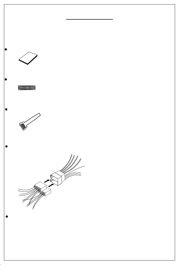
ACCESSORIES
When first unpacking your new in Car Radio CD Player, please check first that the package
contains all of the items below. If something is missing, contact the store where you purchased
the player.
Owner’s Manual
O
m n a
w
n
er s
a u
’
l
Spare Fuse
2 x Release key
For use when ISO plugs are not used on your vehicle
Main Unit
ISO Socket
1 X 5mm nut
1 X spring washer
1 12mm self-tapping screw
1 X 5mm screw
1 X support strap
1 X plain washer
P. 3
Page 4
INSTALLATION
Before finally installing the unit, carry out a sound check. If high distortion or intermittent sound
is experienced, it is possible that the wiring to the car's electric is poor, or that the battery needs
recharging.
Use only the parts included with the unit to ensure a safe and secure installation.
Consult with your nearest dealer if installation requires the drilling of holes or other
modifications to the vehicle.
Choose a mounting location carefully so that the unit will not interfere with the normal driving
functions of the vehicle.
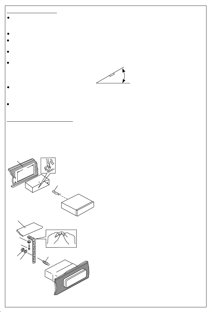
If installation angle exceeds 30° from horizontal, the unit might not give its optimum
performance.
Avoid installing the unit where it would be subject to high temperature, such as from direct
sunlight, or from hot air, from heater, or where it would be subject to dust dirt or excessive
vibration.
Be sure to remove the front panel before installing the unit.
DIN FRONT/REAR-MOUNT
This unit can be installed either from “Front” (conventional DIN Front-mount) or “Rear”(DIN
Rear-mount installation, utilizing threaded screw holes at the sides of the unit chassis). For details,
refer to the following illustrated installation methods A and B.
- DIN FRONT-MOUNT (Method A)
1
182
53
2
1. Dashboard
2. Mounting sleeve
3
3. Screw
30°
After inserting the half sleeve into the
dashboard, select the appropriate tab
according to the thickness of the
dashboard material and bend them
inwards to secure the sleeve in place.
1
7
4
2
3
6
5
1. Dashboard
2. Nut (5mm)
3. Spring washer
4. Screw (4x12mm)
5. Screw
6. Support Strap
Be sure to use the support strap to
secure the back of the unit in place. The
strap can be bent by hand to the desired
angle.
7. Plain washer
P. 4
Page 5
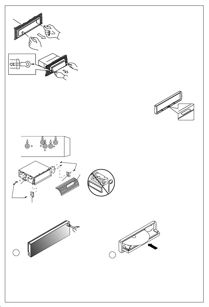
Removing the unit
a
a. Frame
b. Insert fingers into the groove in the
front of frame and pull out to remove
the frame. (When re-attaching the
frame, point the side with a groove
b
c
down wards and attach it.)
c. Insert the levers supplied with the
unit into the grooves at both sides of
the unit as shown in figure until they
click. Pulling the levers makes it
possible to remove the unit from the
dashboard.
- Trim Ring Installation:
Before attaching the trim ring, the side with a "Bottom" Label should be
seen on the lower edge of the ring (as shown on diagram).
Push the trim plate against the main panel until it clicks into place.
- DIN REAR-MOUNT (METHOD B)
Installation using the screw holes on the sides of the unit.
Fastening the unit to the factory radio mounting bracket.
1. Select a position where the screw
holes of the bracket and the screw
holes of the main unit become
aligned (are fitted) and tighten the
screws at 2 places on each side.
2
4
5
3
2. Screw
3. Factory radio mounting bracket.
4. Dashboard or Console
5. Hook (Remove this part)
Note: the mounting box, outer trim ring,
and half-sleeve are not used for method
2
B installation.
5
- PANEL OPEN/CLOSE OPERATION
O
TM
T
O
B
M
T
T
O
B O
T
E
S
E
R
1
2
N
I
D
C
1. Press Open button
2. The CD slot will be accessible.
3. After CD is loaded or unloaded return the panel to its original position.
P. 5
Page 6
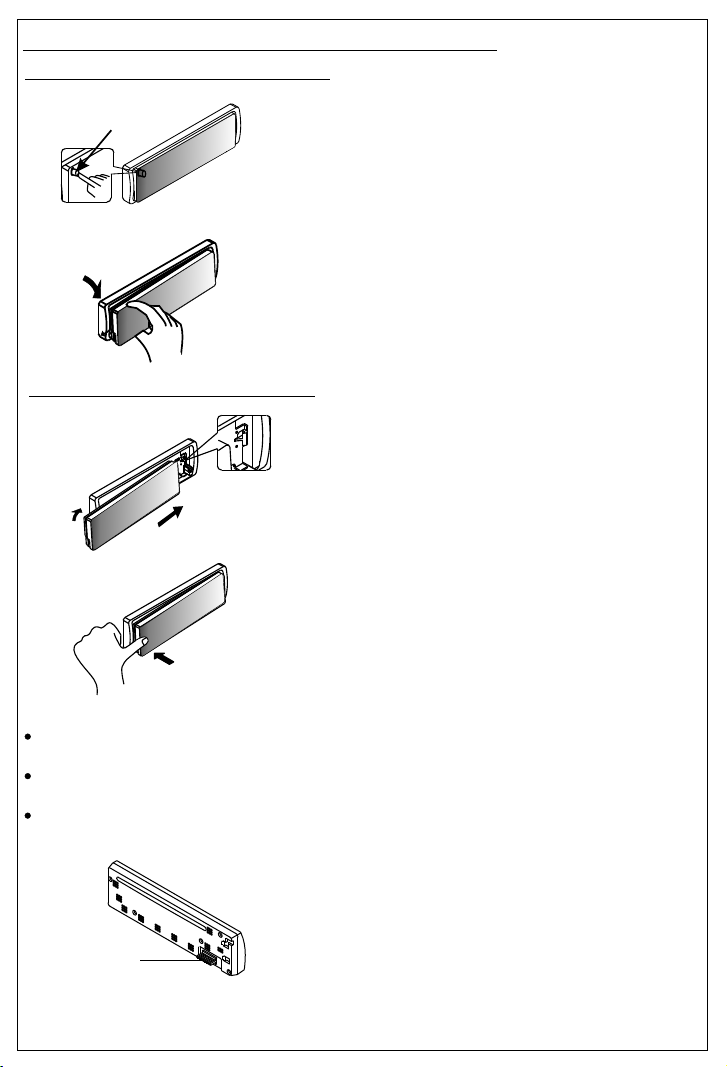
USING THE DETACHABLE FRONT PANEL
Removing The Detachable Front Panel
RELEASE
BUTTON
Attaching the Detachable Front panel
1.
2.
1. Turn the Power off.
2. Press the Panel Release Button.
3. Remove the front panel
1. Insert the right side of the
front panel into the main unit.
2. Press the left hand side of
the front panel until a "click"
sound is heard
HPUS
Precautions when handling the Detachable Front Panel
Always insert the front panel in the manner described above. Failure to do so may damage
both the panel and the main unit.
Do not drop the front panel. Always place it the the protective case provided when not in
use.
Do not touch the contacts on the front panel or the main unit. It may result in a poor
electrical connection.
Note:
If the front panel is dirty, wipe off the dirt with
soft, dry cloth only. To clean the contacts on
the front panel, use a cotton swab soaked in
isopropyl alcohol.
Socket
P. 6
Page 7

WIRING IDENTIFICATION
ANTENNA JACK
ANTENNA
CABLE
RCA-TO-RCA CABLES
(not supplied)
AMP
WHITE
L-CHR-CH
RED
REAR LINE OUT
GREY
20-PIN
AUDIO/POWER
HARNESS
(YELLOW)
Battery wire
FUSE
(RED)
Ignition wire
(Not Supplied)
CONNECTOR B
ISO CONNECTOR 4PIN+8PIN
FEMALE WITH MALE TERMINAL
ISO CONNECTOR WIRING CHART
WIRE COLOR
PIN
A4
YELLOW
A5
BLUE
A7
A8
B1
B2
B3
B4
B5
B6
B7
B8
RED
BLACK
VIOLET
VIOLET / BLACK
GREY
GREY / BLACK
WHITE
WHITE / BLACK
GREEN
GREEN / BLACK
P. 7
7 87 8
5 65
6
3 4
3
4
1 2
1
2
Figure 2
FUNCTION / LABEL
POWER ANTENNA
RIGHT REAR SPEAKER (+)
RIGHT REAR SPEAKER (-)
RIGHT FRONT SPEAKER (+)
RIGHT FRONT SPEAKER (-)
LEFT FRONT SPEAKER (+)
LEFT FRONT SPEAKER (-)
LEFT REAR SPEAKER (+)
LEFT REAR SPEAKER (-)
YELLOW
CONNECTOR
(See Figure 2)
CONNECTOR A
BATTERY (+)
IGNITION(ACC)
GROUND
RED
ISO
Page 8

INSTALLATION NOTES
The default connection for the wiring harness is as described in 1 below. If the ISO connectors pins are set as
described in 2 or 3 ,please make the correct connection as illustrated in 2 or 3 .
Note: Make sure that the ISO connections on the unit match those of the vehicle before
connecting.
1 Default setting. The A-7 pin (red ) of the vehicle’s ISO connector is linked to the ignition. And the A-4 pin (yellow)
is connected to the constant power supply ( battery ):
2 The A-7 pin ( red ) of the vehicle’s iso connector is connected to the constant power supply ( battery ) and the
A-4 pin ( yellow )is linked to the ignition, then please change the connections of the red & yellow wire by using the
small connector on these two wires as illustrated below :
3 The A-4 pin ( Yellow ) of the vehicle’s iso connector is not connected to anything . The A-7 pin is connected to
the constant power supply ( or both the A-7 ( Red ) and A-4 ( Yellow ) pins are connected to the constant power
supply ).
Warning : If you make the connection as 3 , the unit’s power will not be linked to the ignition key. For that reason,
always make sure to turn off the unit’s power when the ignition is turned off, otherwise it may drain the car’s
battery,
To link the unit’s power to the ignition, connect the ignition cable ( Acc--Red ) to a power source that can be turned
on and off with the ignition key.
P. 8
Page 9

IDENTIFICATION OF CONTROLS AND FUNCTIONS
14
15
AUX
6
11
17
16
5
12
VOLVOL
2
4
9
3
8
SCN
SHF
10
40wx 440wx4
7
1. POWER BUTTON
2. VOLUME CONTROL KNOB
3. DISPLAY BUTTON
4. MENU BUTTON / SELECT BUTTON
5. PANEL RELEASE BUTTON
6. TA BUTTON
7. AF BUTTON
8. LCD DISPLAY
9. AMS BUTTON
10. PRESET MEMORY STATION BUTTONS
11. PTY BUTTON
12. TUNING SEEK UP /DOWN & TRACK UP/DOWN BUTTONS
13. PANEL OPEN BUTTON
14. BAND BUTTON
15. SCAN BUTTON
16. MODE BUTTON
17. AUX-IN SOCKET (behind cover)
13
P. 9
Page 10

LCD DISPLAY
6
1. STEREO : Radio stereo indication
2. TP : RDS Traffic programme indication
3. AF : RDS Alternative frequency indication
4. TA : RDS Traffic announcement indication
5. PTY : RDS Programme type indication
6. Preset radio station indication (1 to 6)
NOTE:
LCD Screen
In extreme cold, the screen movement may slow down and the screen may darken, but
this is normal.
The screen will recover when the unit warms up, or the ambient temperature rises.
P. 10
Page 11

GENERAL OPERATION
1) POWER BUTTON
Press power button to turn on/off the unit.
4) MENU/ SELECT BUTTON
You can operate the following function through MENU/SELECT button.
A. AUDIO MENU
press the MENU/SELECT button for less than 1 second to open the Audio menu.
press MENU/SELECT repeatedly to navigate through the following functions:
VOLUME (VOL) -> BASS (BAS) -> TREBLE (TRE) -> BALANCE (BAL) -> FADER (FAD)
Rotate Volume Control to adjust desired level.Note that the unit will return to it's previous
state after 5 seconds when no further adjustments have been made.
B. ADVANCED MENU
press & hold the MENU /SELECT button for more than 2 seconds to open the Advanced
Menu. Press MENU/SELECT button repeatedly to navigate through the menu items. When
the desired menu item is displayed, use the Volume control to adjust the desired setting:
- TA SEEK TA ALARM
To determine what action the radio will take if a newly tuned station does not receive TP
information for 5 seconds.
TA SEEK
The radio retunes to a different station which contains TP information.
TA ALARM
The radio does not retune but will make an audible beep sound.
- PI SOUND, PI MUTE
If you are travelling on the fringe area of two transmitters, you may receive conflicting AF
information. When the vehicle is crossing the area where two stations with same AF but different PI
code can be received at the same time, the receiver may become unstable. Under this situation
Two modes can be selected.
PI SOUND
The different PI sounds will be heard.
PI MUTE
Under the same situation, the radio will be muted.
- RETUNE L, RETUNE S
To determine the initial time of automatic TA search or PI search.
RETUNE L 90 seconds
RETUNE S 30 seconds
- MASK PI, MASK ALL
“PI” is referred to “Different PI with same AF”.
During AF search, PI stations and non-RDS stations with strong signal will be masked, in the latter
case, the non-RDS stations may cause interference, resulting the real AF to be masked due to the
misjudgment of the radio under interference.
There are two options to handle this situation.
MASK PI to mask only the AF with different PI.
MASK ALL mask both PI and strong signal non-RDS stations.
- BEEP 2ND, BEEP ALL, BEEP OFF
To determine how the beep sound is generated when the buttons are pressed.
BEEP 2ND Beeps only when the second function of the dual function button is selected.
BEEP ALL Beeps when any button is pressed.
BEEP OFF To disable the beep option.
P. 11
Page 12

- DSP (PRESET EQUALIZER)
DSP OFF -> FLAT -> CLASSIC -> POP -> ROCK
When DSP OFF is selected, the Bass & Treble can be adjusted (See Audio Menu).
- LOUD
When Loud ON is selected, bass output will be increased.
- DX
Use this mode to change between Local and Distant (-DX) tuning mode. Local mode
improves reception in some areas where the signal is too strong.
- STEREO
Use this mode to select stereo or monaural reception for FM radio stations. You can
sometimes improve reception of distant stations by selecting mono mode.
2) VOLUME KNOB
When the Menu function is not activated, rotate this knob to change the volume level.
When Menu function is activated, rotate this knob to change the settings of the various menu
items.
16) MODE BUTTON
Press this button to select the different modes available on this unit: Tuner, CD (only if a CD
is inserted) and AUX in.
AUX INPUT
Connect the external signal to AUX in socket located
on the front of the panel , then press Mode button to
select Aux mode. Press Mode Button again to cancel
Aux Mode and return to previous mode.
3) DISPLAY BUTTON (DISP)
Press this button to view Clock, Programme Type (PTY), and Frequency of the current station.
15) SCAN BUTTON(SCAN)
Press this button to scan to the next available radio station. The new station will flash until it
is either selected (by pressing Scan button), or if not selected, the unit will continue to scan
until a desired station is found.
9) AUTO MEMORY STORE / PRESET SCAN BUTTON (AMS)
PRESET SCAN: press AMS button for less than 1 second to scan all preset stations stored in the
memory of the current band. The memory location indicator on the LCD will flash
during the process. To stop preset scan, press AMS button again.
AUTO MEMORY STORE: press AMS button for more than 1 second to enter auto store mode. The
radio will automatically store 6 stations to the 6 preset memories of the current band. To stop auto
store, press AMS button again.
12) TUNING / SEEK UP AND TUNING / SEEK DOWN BUTTONS
1.Pressing these buttons briefly will operate the AUTO SEARCH tuning mode. The radio will
tune up or down to the next station and remain on the frequency.
2.Pressing these buttons for more than 2 seconds and the unit will switch to MANUAL
SEARCH mode. This allows fine tuning of the radio. Briefly press the buttons to make
small adjustments, or press and hold to search through the band quickly.
14) BAND BUTTON
Press this button to change between band FM or MW(AM).
P. 12
Page 13

RESET BUTTON
In case of abnormal operation, use a pencil tip or other non-metallic object to press the
reset button located behind the front panel. The reset button should be activated in the
following circumstances:
- Initial installation of the unit when all wiring is completed.
- If the control function buttons do not operate.
TS
E
E
R
T
E
S
RE
- An abnormal or error symbol shown on the display.
8) LIQUID CRYSTAL DISPLAY PANEL (LCD)
The LCD panel displays the frequency, time and activated functions.
10) STATION PRESET BUTTONS
You can store & recall six preset radio stations using the numbered buttons 1-6.
TO STORE A STATION: 1) select a band (if needed)
2) select a station by tuning up / down button
3) hold the preset button which you want store the station for at
least 2 seconds. The preset number will appear on the display
accompanied by a beeps sound.
TO RECALL A STATION: 1) select a band (if needed)
2) press a preset button briefly to recall the stored station.
P. 13
Page 14

RDS OPERATION
7) AF BUTTON(ALTERNATIVE FREQUENCIES)
When pressed briefly, AF switching mode is selected.
When AF switching mode is selected, the radio will check the signal strength of the AF
constantly.
When pressed for 2 seconds, it will activate the regional mode.
Note: To check whether an alternative frequency is a real alternative for the current
station, the radio compares PI codes (programme identity).
- Regional mode ON:
The PI codes must be identical. REG icon will show in the display.
- Regional mode OFF:
The regional identification code in the PI code is ignored.
Some broadcasting stations may change their program from normal broadcasting to regional
broadcasting for a certain period. When regional mode is off, the region identification in the PI
code is ignored; the radio may switch to a local variant of the current program. When region
mode is on, the radio will only switch to a program carrying the exact same PI code.
Note: If AF is selected, when the tuning up/down buttons are used, the unit will only
search for stations with RDS data.
6)TA BUTTON(TRAFFIC ANNOUNCEMENT)
When pressed briefly, TA mode will be switched on. Press again to switch TA mode off.
The following will happen if TA mode is selected and a traffic announcement is transmitted:
- When the unit is in CD mode, it will switch to radio mode temporarily.
- If the volume is set to a low level, it will be raised to a preset level.
- TP will show in the display when the unit is tuned to a station that is capable of broadcasting
traffic information.
When pressed for more than 2 seconds, EON TA LOCAL /EON TA DISTANCE mode is selected.
- EON TA LOCAL mode
TA reception can be adjusted to receive local or local + long distance announcements.
Note: If TA is selected, when the tuning up/down buttons are used, the unit will only
search for stations that broadcast traffic announcements.
12)PTY BUTTON
When this button is pressed, the PTY mode will toggle in the following order:
PTY Music Group -> PTY Speech Group ->PTY Off
The current PTY code is displayed on the LCD, use the 6 preset buttons to select the other
PTY codes, the distribution of program types are as follows:
Button Number
1
2
3
4
5
6
When PTY code is selected, the radio will search the band for the station that matches the
PTY code.
Music Group
POP , ROCK
EASY, LIGHT
CL A S S I C S ,
JAZZ, COUNTRY
NATION, OLDIES
FOLK
Speech Group
NEWS, AFFAIRS, INFO
SPORT, EDUCATE, DRAMA
CULTURE, SCIENCE, VARIED
WEATHER,FINANCE, CHILDREN
SOCIAL, RELIGION, PHONE IN
TRAVEL, LEISURE, DOCUMENT
P. 14
Page 15

OVERVIEW OF THE RDS FUNCTION
Radio Data System (RDS) is a broadcasting service that allows FM stations to send additional
digital information along with the regular radio program signal. Your car stereo offers you a variety
of services. Here are just a few:
- PI (Program identification)
It is a code that identifies RDS stations; it is unique for each station.
- PS (PROGRAM Service Name)
The name of current station.
- AF (Alternative Frequencies List)
The list(s) of Alternative Frequencies give information on the various transmitters broadcasting
the same program in the same or adjacent reception area. If the main frequency should get
worse, the radio will tune automatically to the strongest Alternative frequency.
- TP (Traffic Program)
If the tuned program broadcasts traffic announcements, the TP indicator will turn on.
- TA (Traffic Announcement)
When an actual traffic bulletin is on air, the TA indicator will also turn on.
- PTY (Program Type Codes)
This code is used to designate the current program material being broadcast. With this feature,
you can search the programs that match the selected program type, which is chosen from a
specific list of types.
- EON (Enhanced Other Networks Information)
It is a supplementary service enabling the radio to obtain information not only from the current
station but also from other networks.
Notes
RDS may not work properly if the signal strength is weak or if the station you are tuned to is not
transmitting RDS data.
P. 15
Page 16

CD OPERATION
LOADING THE CD
Press the Panel Fold Down Button to lower the front panel. Insert the disc through CD slot, the
disc will be automatically loaded and playback will start.
CD EJECT BUTTON
Press this button to eject the CD. Since this button is located behind the front panel, fold down
the panel before accessing this button.
ET
S
E
R
1) CD PLAY/PAUSE BUTTON
Press this button briefly to pause CD play, press again to continue CD playback.
2) INTRO SCAN BUTTON
Press this button to select Intro Scan function, the first 10 seconds of each track will be played
sequentially until this button is pressed again, then normal play will resume at the current track.
3) REPEAT BUTTON
Pressing this button will activate Repeat Function in the following order :
Repeat On Repeat Off
The RPT indicator in the display will turn on.
4) SHUFFLE BUTTON (SHF)
Press this button to play all tracks on a CD in a random order. Press again to resume normal
playback at the current track.
12) TRACK UP AND TRACK DOWN BUTTON
During CD playback, press these buttons to skip to the next / previous track.
To search for a particular part of a track, press and hold either button to enter Cue/Review
mode. When the button is released, normal playback resumes.
P. 16
Page 17

NOTE ON DISCS
MOISTURE CONDENSATION
In damp or humid conditions, moisture may condense on the lense inside the unit. Should this
occur, the unit will not operate properly. To restore correct operation, please remove the CD
and allow 1 hour for any moisture to evaporate.
NOTES ON CDs
1.
A dirty or defective disc may cause sound
dropouts while playing. To enjoy optimum
sound, handle the disc as follows.
Handle the disc by its edge. To keep the disc
clean, do not touch the surface (P.1).
NOTES ON DISCS
If you use the discs such as those shown
below, the sticky residue can cause the CD
to stop spinning and may cause
malfunction or ruin your discs.
Do not use second-hand or rental CDs that
have a sticky residue on the surface (for
example, from peeled-off stickers or from
ink, or glue leaking from under the stickers).
P. 1
Do not stick paper or tape on the disc (P.2).
2.
P. 2
Do not expose the discs to direct sunlight or
3.
heat sources such as hot air-ducts, or leave
them in a car parked in direct sunlight where
there c an be a considera ble rise in
temperature inside the car (P.3).
P. 3
Before playing, clean the discs with an
4.
optional cleaning cloth. Wipe each disc from
the centre out (P.4).
P. 4
Do not use solvents such as benzine, thinners,
5.
commercially available cleaners, or antistatic
spray intended for analog discs.
*******
*******
*******
P. 5
Do not use rental CDs with old labels that
are beginning to peel off.
Stickers that are beginning
to peel away, leaving a
sticky residue (P.6).
P. 6
Do not use your CDs with labels or stickers
attached.
Labels are attached (P.7).
Do Not Use Special Shape CDs
P. 7
Use of special shape CDs may cause the
unit to malfunction.(P.8).
P. 8
Be sure to use CDs with these markings
RECORDABLE
REWRITABLE
Only for this unit.
CD-Rs and CD-RWs which have not
undergone finalization processing cannot
be played. (For more information on
finalization processing, refer to the manual
for your CD-R/CD-RW writing software or
CD-R/CD-RW recorder.) Additionally,
depending on the recording status, it may
prove impossible to play certain CDs
recorded on CD-R or CD-RW.
P. 17
*******
*******
****
**************
*******
*******
*******
*******
*******
*******
*******
Page 18

SPECIFICATIONS
CD PLAYER
System
Usable disc
Sampling frequency
No of quantization bits
Frequency
Number of channels
S/N Ratio
RADIO SECTION
FM
Frequency Range
Intermediate Frequency
Usable Sensitivity
Stereo Separation
S/N Ratio
AM (MW)
Frequency Range
Intermediate Frequency
Usable Sensitivity
S/N Ratio
GENERAL
Power Supply
Speaker impedance
Power Output
Chassis Dimensions (in mm)
Weight
Compact disc audio system
Compact disc
44.1KHz
1bit
5-20,000Hz
2 stereo
70dB
87.5 - 108 Mhz
10.7 MHz
Better than 15dB at S/N 30 dB
25 dB at 1KHz
50 dB
522 - 1620 Khz
450KHz
Better than 45dB
40 dB
DC 11 -14V, Negative ground
4 ohms
40W x 4
178W X 175D X 50H
1.6Kg
NOTE
Specifications are subject to change without prior notice.
P. 18
Page 19

TROUBLE SHOOTING
Before going through the check list, first refer back to the connection and operating procedures.
Most problems that you may encounter with your unit are covered in the list below. Should any problems
persist after you have checked this list, please contact our Customer Helpline on 0871 230 1777 for further
assistance.
Symptom
No power
The car ignition is not on.
Cause
Solution
If the power supply is properly connected
to the car accessory terminal, switch the
ignition key to “ACC”
Disc cannot be loaded
or ejected
No sound
The operation keys do
not work
Sound skips.
The radio does not
work.
The radio station
automatic selection
does not work.
ERROR 1
ERROR 2
If at any time in the future you should need to dispose of this product please note
that Waste electrical products should not be disposed of with household waste.
Please recycle where facilities exist. Check with your Local Authority or retailer
for recycling advice.(Waste Electrical and Electronic Equipment Directive)
The fuse is blown.
Presence of CD disc inside
the player.
Inserting the disc in reverse
direction.
Compact disc is extremely
dirty or defective disc.
Temperature inside the car is
too high.
Condensation.
Volume is set to minimum.
Wiring is not properly
connected.
The built-in microcomputer is
operating incorrectly.
The installation angle is
more than 30 degrees.
The disc is extremely dirty or
defective.
The antenna cable is not
connected.
The signals are too weak.
Mechanism Error
Servo Error
P. 19
Replace the fuse.
Remove the disc in the player, then try
again.
Insert the compact disc with the label
facing upward.
Clean the disc or try to play a new one.
Cool off or until the ambient temperature
returns to normal.
Leave the player to off for an hour or so,
then try again.
Adjust volume to a desired level.
Check wiring connection.
Press the RESET button.
Front panel is not making good contact with
the connections pins on the main unit.
Adjust the installation angle to less 30
degrees.
Clean the compact disc, or try to play a
new one.
Insert the antenna cable firmly.
Select a station manually.
Press the reset button If the error is still
evident after pressing the reset button,
consult our Customer helpline.
Press the reset button If the error is still
evident after pressing the reset button,
consult our Customer helpline.
Page 20

cecustomerser vice@a lbaplc .co.uk
helpline number: 0871 230 1777
P. 20
 Loading...