

Page 1

Replacement Parts List No. 0700051700
New 09/2015
Daikin
MagnitudeTM
Magnetic Bearing
Centrifugal Chiller
WME
1500
Vintage B
To nd your Daikin Applied parts distributor, call 1-800-377-2787 or visit www.DaikinApplied.com
Page 2

Contents
Parts List Revision History.................................................................................................................................. 3
Nomenclature
Model and Serial Number Nomenclature ..................................................................................................... 4
Model Number- Complete ....................................................................................................................... 5 - 9
Electrical Legend .............................................................................................................................................. 10
Controls
Main Control Box ........................................................................................................................................11
VFD Enclosure ........................................................................................................................................... 12
VFD Chassis ....................................................................................................................................... 13 - 14
VFD Power Supply Plate .................................................................................................................... 15 - 16
OITS- Operator Interface Touch Screen .................................................................................................... 17
Control Sensors ......................................................................................................................................... 18 - 19
Compressor
Motor/Bearing Assemblies .................................................................................................................. 20 - 21
Impeller Assembly ..................................................................................................................................... 22
Impeller Seal & Compressor Fittings .................................................................................................. 23 - 24
Discharge Housing & High Speed Shaft Seal ........................................................................................... 25
Inlet Assembly ..................................................................................................................................... 26 - 27
Unit Assembly
Relief & Shutoff Valves- Diagrams ...................................................................................................... 28 - 29
Discharge Piping Stack .............................................................................................................................. 30
Range Extension ................................................................................................................................. 31 - 32
Suction and Discharge Piping .................................................................................................................... 33
Liquid Injection ........................................................................................................................................... 34
Rotor Cooling ...................................................................................................................................... 35 - 36
Stator Cooling ..................................................................................................................................... 37 - 38
VFD Cooling ........................................................................................................................................ 39 - 40
Liquid Line ........................................................................................................................................... 41 - 42
Expansion Valve......................................................................................................................................... 43
Condenser
Diagrams .................................................................................................................................................... 44
42 Inch - Dish Head Gaskets & Hardware ................................................................................................. 45
42 Inch - Water Box Head Gaskets & Hardware ........................................................................................ 46
Sight Glass, Shut Off Valve & Gasket, Charge Valve ................................................................................ 47
Evaporator
Diagrams .................................................................................................................................................... 48
48 Inch - Dish Head Gaskets & Hardware ................................................................................................. 49
48 Inch - Water Box Head Gaskets & Hardware ........................................................................................ 50
Sight Glass, Charge Valve ......................................................................................................................... 51
Critical Parts List............................................................................................................................................... 52
WME1500DB- Water Cooled Chiller New 09/15 RPL 7000517 / Page 2
Page 3
Parts List Revision History
Revision Date Description
New 09/2015 New
Daikin Applied, 13600 Industrial Park Blvd., P.O. Box 1551, Minneapolis, MN 55440 (763) 553-5330
WME1500DB- Water Cooled Chiller New 09/15 RPL 7000517 / Page 3
Page 4

Model and Serial Number Nomenclature
Model Number Nomenclature
Unit Type:
WME = Magnetic Bearing Centrifugal Chiller,
Water Cooled
Unit Size:
1000 Nominal Tons
Nomenclature
WME 1500 D B
Vintage
Number of Compressors
D = Dual Compressor
Plant Identication
STN = Staunton, VA
U = Unit
Serial Number Nomenclature
STN U 15 05 04810
Year of Manufacture
14 = 2014
15 = 2015
16 = 2016
17 = 2017
etc.
Serial Number
(Build Sequence)
Month of Manufacture
01 = January
02 = February
03 = March
04 = April
05 = May
06 = June
07 = July
08 = August
09 = September
10 = October
11 = November
12 = December
WME1500DB- Water Cooled Chiller New 09/15 RPL 7000517 / Page 4
Page 5
Nomenclature
Model Number- Complete
Code: WME 1500D B SN M3 00460 H6 D C E4816 GB 2 C DK L 2 V C N C
Code No.: 1 2 3 4 5 6 7 8 9 10 11 12 13 14 15 16 17 18 19 20
4 440F 00580 C C N A C4216 GB 2 C DR N N N NN L 2 V
21 22 23 24 25 26 27 28 29 30 31 32 33 34 35 36 37 38 39
C N D 4 1050F 00725 C C N N NN A A 0150 A 0700 E7 EA E N
40 41 42 43 44 45 46 47 48 49 50 51 52 53 54 55 56 57 58 59
N A 01020 M D N N S N N R S H N B 1 5 A N N N
60 61 62 63 64 65 66 67 68 69 70 71 72 73 74 75 76 77 78 79 80
F N N E A A N J 000 U Y N 0 A N S S U A 12345
81 82 83 84 85 86 87 88 89 90 91 92 93 94 95 96 97 98 99 100
NNNNNNNNNNN NN NNNNN VFDM400 D NNNN N C3 04V
101 102 103 104 105 106 107 108 109
1. Model Type
WME= Magnetic Bearing Centrifugal Chiller, Water Cooled
2. Unit Size / Number of Compressors
1500D= 1500 Tons, Dual Compressor
3. Vintage
B= Vintage B
4. Chiller Conguration
SN= Single Refrigerant Circuit w/o Economizer
5. Motor Code
M4= 6 Winding, 6PH, 380-480V
6. Power Supply Voltage
00380= 380V; 00400= 400V; 00415= 415V; 00440= 440V; 00460= 460V; 00480= 480V; 00575= 575V
7. Power Supply Hertz
H5= 50 Hertz; H6= 60 Hertz
8. Always D
9. Compressor Model Revision
C= Revision C
10. Evaporator Shell Size
E4816= Evaporator, 48" Diameter/16' Long
11. Evaporator Tube Count and Conguration
GB= Design B, 3/4" Diameter Tube, Qty=963
HB= Design B, 3/4" Diameter Tube, Qty=863
JB= Design B, 3/4” Diameter Tube , Qty=757
SD= Design D, Mixed Tubes, Qty= 553 of 3/4" + 222 of 1"
TD= Design D, Mixed Tubes, Qty= 499 of 3/4" + 200 of 1"
VE= Design E, 1” Diameter Tube, Qty=509
WE= Design E, 1” Diameter Tube, Qty=459
YE= Design E, 1” Diameter Tube, Qty=392
WME1500DB- Water Cooled Chiller New 09/15 RPL 7000517 / Page 5
Page 6

Nomenclature
Model Number- Complete, Continued
12. Evaporator Tube Wall Thickness
2= 0.025"
3= 0.028"
5= 0.035"
13. Evaporator Tube Type
C= CU
N= CN90/10
14. Evaporator Tube Model
15. Evaporator Inlet Nozzle Location
L= Left
R= Right
16. Evaporator Water Passes
1= 1 Pass
2= 2 Pass
3= 3 Pass
17. Evaporator Inlet Nozzle Connection Type
V= Groove
F= Flanged
18. Evaporator Inlet Nozzle Conguration
A= Dish, End; 1-Pass
B= Dish, End; 2 or 3 Pass
D= Water Box, Top; 1-Pass
E= Water Box, Rear; 1-Pass
H= Water Box, Rear; 2 or 3 Pass
19. Evaporator Hinged Type
N= None
H= Standard Hinges on Both Ends
20. Evaporator Refrigerant Design Pressure
C= 200 PSIG
27. Evaporator Model Revision
A= Revision Level A
28. Condenser Shell Size
C4216= Evaporator, 42” Diameter/16’ Long;
29. Condenser Tube Count and Conguration
GB= Design B, 3/4” Diameter Tube, Qty=1365
HB= Design B, 3/4” Diameter Tube, Qty=1221
JB= Design B, 3/4” Diameter Tube , Qty=1090
VE= Design E, 1” Diameter Tube, Qty=810
WE= Design E, 1” Diameter Tube, Qty=732
YE= Design E, 1” Diameter Tube, Qty=645
30. Condenser Tube Wall Thickness
2= 0.025”
3= 0.028”
5= 0.035”
31. Condenser Tube Type
C= CU
N= CN90/10
S= Stainless Steel
T= Titanium
32. Condenser Tube Model
33-36. Future Use
37. Condenser Inlet Nozzle Location
L= Left
R= Right
38. Condenser Water Passes
1= 1 Pass
2= 2 Pass
3= 3 Pass
21. Evaporator Water Side Design Pressure
4= 150 PSIG, Non-ASME Code
39. Condenser Inlet Nozzle Connection Type
V= Groove
F= Flanged
22. Evaporator Leaving Water Temperature
Example: 440= 44.0 °F
23. Evaporator GPM
Example: 00580= 580 GPM
24. Evaporator Tube Sheet Coating/ Material
C= Carbon Steel
E= Enecon Coating; Outside of Tube Sheet
25. Evaporator Head/ Water Box Coating/ Material
C= Carbon Steel
E= Enecon Coating; Inside of Head
D= Devcon Coating; Inside of Head
26. Evaporator Head Tube Cleaning System
N= None
40. Evaporator Inlet Nozzle Conguration
A= Dish, End; 1-Pass
B= Dish, End; 2 or 3 Pass
D= Water Box, Top; 1-Pass
E= Water Box, Front; 1-Pass
H= Water Box, Front; 2 or 3 Pass
41. Condenser Hinged Type
N= None
H= Standard Hinges on Both Ends
42. Condenser Refrigerant Design Pressure
D= 225 PSIG
43. Evaporator Water Side Design Pressure
4= 150 PSIG, Non-ASME Code
WME1500DB- Water Cooled Chiller New 09/15 RPL 7000517 / Page 6
Page 7

Nomenclature
Model Number- Complete, Continued
44. Condenser Leaving Water Temperature
Example: 1050= 105.0 °F
45. Condenser GPM
Example: 00725= 725 GPM
46. Condenser Tube Sheet Coating/ Material
C= Carbon Steel
E= Enecon Coating; Outside of Tube Sheet
M= Monel Clad
S= Stainless Steel Clad
T= Titanium Steel Clad
47. Condenser Head/ Water Box Coating/ Material
C= Carbon Steel
E= Enecon Coating; Inside of Head
D= Devcon Coating; Inside of Head
48-49. Future Use
50. Condenser Tube Cleaning System
NN= None
51. Condenser Model Revision
A= Revision level A
52. Pressure Vessel Code
A= ASME
53. Unit Tons
Example: 0150= 150 Tons
62. Input Rated Load Amps (RLA) - Compressor #1
Example: 01020= 102.0 Amps
63. Starter Box #
M= Multiple Point - Dual Starter Boxes
64. Power Connection Type
D= Disconnect Switch
65. EMI Filter
N= None
4= 400A Input Current EMI Filter
66. Surge Protection
N= None
67. Short Circuit Current Ratings
S= SCCR 35KA
H= SCCR 65KA
V= SCCR 100KA
L= SCCR 25KA (For 575V only)
M= SCCR 50KA
68. Ground Fault Protection
N= None
F= With Ground Fault Protection Relay
69. Harmonic Filter
N= None
1= 300 HP
2= 350 HP
3= 400 HP
54. Refrigerant Type
A= Refrigerant 134A
55. Refrigerant Weight
Example: 0700= 700 Pounds
56. Electronic Expansion Valve Circuit #1
E7= Electronic Valve Size 7
57. Controller Type
EA= MicroTech-E (Rev. A)
58. Controller Language
E= English - English Units
59. Controller Rapid Restore
N= None
60. Controller Communications
N= None
B= BACnet (MS/TP, IP/Ethernet)
L= Lonmark
M= Modbus
61. Starter Box & Unit Controller Box Type
A= NEMA 1
70. Range Extension
R= Range Extension System
71. Compressor Sound Reduction
Sound Reduction Pkg - Sound Insulation on Dchrg Line
72. Evaporator Insulation
N= None
H= 3/4" Insulation on Evap. Shell, Suction Piping,
and Compressor Inlet
3= 1-1/2" Insulation on Evap. Shell, Suction Piping,
and Compressor Inlet
73. Head Insulation
N= None
2= Evap. Return and Connection Heads Insulated
74. Factory Water Flow Indicatior
B= Both Evaporator and Condenser Flow Control
75. Unit Paint
1= Standard Painting
76. Shipping/ Packaging
WME1500DB- Water Cooled Chiller New 09/15 RPL 7000517 / Page 7
Page 8

Nomenclature
Model Number- Complete, Continued
77. Refrigerant Charge
A= Full Factory Refrigerant Charge
C= Holding Charge - Nitrogen
78. Special
V= None
X= Special
79. Low Lift Conditions
N= None
80. Knockdown
N= None
A= Type A; Bolted Construction, Shipped Together
B= Type B; Bolted Construction, Shipped as Parts
81-83. Testing
GF= Ground Fault Detection Relay; YY= None
84. Agency Listing
E= ETL/cETL
N= None
85. AHRI Listing
A= AHRI
N= None
86. ASHRAE Listing
A= ASHRAE
N= None
87. OSP-IBC Listing
S= OSP-IBC
N= None
88. Unit Label
J= Daikin
89. Coolant Rating
000= Water on both Evaporator and Condenser
E00= Ex: E10= 10% Ethylene on Evaporator or Condenser or Both
P00= Ex: P10= 10% Propylene on Evaporator or Condenser or Both
90. Startup
91. First Year Warranty
Y= Entire Unit Parts and Labor
P= Entire Unit Parts Only
92. Extended Chiller Warranty
A= 1 year of Extended Warranty on parts only
B= 1 year of Extended Warranty on parts and labor
C= 2 year of Extended Warranty on parts only
D= 2 year of Extended Warranty on parts and labor
E= 3 year of Extended Warranty on parts only
F= 3 year of Extended Warranty on parts and labor
G= 4 year of Extended Warranty on parts only
H= 4 year of Extended Warranty on parts and labor
N= None
93. Refrigerant Warranty
0= None
B= 1 Year
D= 2 Year
F= 3 Year
H= 4 Year
K= 5 Year
94. Delayed Warranty Start
A= 12-18; Additional Months = none
B= 12-20; Additional Months = 2
C= 12-22; Additional Months = 4
D= 12-24; Additional Months = 6
E= 12-26; Additional Months = 8
F= 12-28; Additional Months = 10
G= 12-30; Additional Months = 12
95. Extended Chiller Warranty
A= 1 year of Ext Warranty on compressor parts only
B= 1 year of Ext Warranty on compressor parts & labor
C= 2 year of Ext Warranty on compressor parts only
D= 2 year of Ext Warranty on compressor parts & labor
E= 3 year of Ext Warranty on compressor parts only
F= 3 year of Ext Warranty on compressor parts & labor
G= 4 year of Ext Warranty on compressor parts only
H= 4 year of Ext Warranty on compressor parts & labor
N= None
96. Ship
S= Standard Ship
96-97. Bill of Materials
99. Unit Model Revision
A= Revision Level A
100. Unit kW
101. Stock Unit Modications
NNNNNNNNNNN= None
* * * * * * * * * * *= WME Stock Unit Part Number
102. Expansion Valve #2
NN= None
103. Input Rated Load Amps (RLA) - Compr #2 Only
NNNNN= None
* * * * *= Example: 01020= 102.0 Amps
104. VFD Type and Size
VFDM400= 400A - VFD Max Output Amps - 6 Phase
VFDM450= 450A - VFD Max Output Amps - 6 Phase
VFDM500= 500A - VFD Max Output Amps - 3 Phase
105. Power Assembly
S= Single Power Assembly- 3 Phase
D= Dual Power Assembly - 6 Phase
WME1500DB- Water Cooled Chiller New 09/15 RPL 7000517 / Page 8
Page 9

Nomenclature
Model Number- Complete, Continued
106. Transformer Type
NNNN= None
40SD= 400A AutoTransformer - 3 Phase (SD400-6)
60SU= 600A AutoTransformer - 3 Phase (SU600-6)
50SD= 500A Stepdown AutoTransformer - 6 Phase (SD500-12)
73ST= 730A AutoTransformer - 6 Phase (ST730-12)
73Su= 730A Stepup AutoTransformer - 6 Phase (SU730-12)
107. Power Meter
N= None
M= 7350 Power Meter
108. Cabinet Size
C1= Large Cabinet w/Transformer
C2= Small Cabinet w/o Transformer
C3= Large Cabinet w/o Transformer
109. Circuit Breaker Rating
04V= 380-480V / 400A, 100KA Breaker
05S= 380-480V / 500A, 35KA Breaker
05H= 380-480V / 500A, 65KA Breaker
06S= 380-480V / 600A, 35KA Breaker
06H= 380-480V / 600A, 65KA Breaker
06V= 380-480V / 600A, 100KA Breaker
08S= 380-480V / 800A, 35KA Breaker
08H= 380-480V / 800A, 65KA Breaker
08V= 380-480V / 800A, 100KA Breaker
04L= 575V / 400A, 25KA Breaker
04M= 575V / 400A, 50KA Breaker
06L= 575V / 600A, 25KA Breaker
06M= 575V / 600A, 50KA Breaker
WME1500DB- Water Cooled Chiller New 09/15 RPL 7000517 / Page 9
Page 10
Electrical Legend
Sch. Sym. Description Location
BAS Communication Card Main Control Box
CB1 Circuit Breaker- TX2 Primary VFD Power Supply Plate
CB2- 4 Circuit Breaker- Fans VFD Power Supply Plate
CB4 Circuit Breaker- MCB Trip, Power Meter, ELR, Solenoid VFD Power Supply Plate
CFT1- CFT2 Cooling Fan Control VFD Power Supply Plate
CT1- 6 Current Transducers VFD Chassis
CPU Main Control Board Main Control Box
D1 Diode VFD Chassis
ES Switch- Ethernet Main Control Box
ELR Relay- Earth Leakage VFD Power Supply Plate
EMC EMC Filter VFD Enclosure
EXV1 Electronic Expansion Valve Liquid Line
F1- F2 Fuse- Controls Transformer, 2A 600VAC VFD Power Supply Plate
F3- F5 Fuse- IPS, 6A 600VAC VFD Power Supply Plate
F6- F7 Fuse- 150VDC to DC Power Supply, 10A 600VAC VFD Power Supply Plate
F8- F10 Fuse- Power Meter, 10A 600VAC VFD Power Supply Plate
INPUT I/O Board Main Control Box
IPS Intermediate Power Supply VFD Enclosure
L1- 3 Chopper Chokes/Inductors VFD Chassis
LCD LCD Touch Screen Monitor (OITS) Evaporator
LR Line Reactor VFD Enclosure
MCB Main Circuit Breaker VFD Enclosure
P1- P14 DC Power Distribution Terminals VFD Power Supply Plate
PM Power and Current Meter VFD Power Supply Plate
PS2- PS4 Power Supply- VFD VFD Power Supply Plate
PS5 Power Supply- Chiller I/O VFD Power Supply Plate
PS6 Power Supply- Compressor I/O VFD Power Supply Plate
PS7- PS8 Power Supply- Magnetic Bearings VFD Power Supply Plate
Q1- 3 Chopper/IGBT Driver VFD Chassis
Q4- 6 Steering Bridge IGBT VFD Chassis
R1- 4 Resistors VFD Chassis
S01 Sensor- Evaporator Entering Water Temperature Evaporator Inlet
S02 Sensor- Evaporator Leaving Water Temperature Evaporator Outlet
S04 Switch- Evaporator Entering Flow Evaporator Inlet
S05 Sensor- Condenser Entering Water Temperature Condenser Inlet
S06 Sensor- Condenser Leaving Water Temperature Condenser Outlet
S07 Sensor- Condenser Refrigerant Pressure Condenser
S08 Switch- Condenser Entering Flow Condenser Inlet
S09 Sensor- Liquid Line Temperature Liquid Line
S10 Sensor- Compressor Suction Temperature Compressor
S11 Sensor- Compressor Suction Pressure Compressor
S12 Sensor- Compressor Discharge Temperature Compressor Discharge Housing
S13 Sensor- Compressor Discharge Pressure Compressor Discharge Housing
S14 Sensor- Motor Gap Temperature Compressor
S15 Switch- High Pressure Discharge Piping
SW1 Switch- Compressor #1 Main Control Box
SW3 Switch- Remote Start/Stop Remote Mounting
SW4 Switch- Mode Remote Mounting
SW5 Switch- Unit Enable Main Control Box
TDM1- 3 Diode/Thyristor Module VFD Chassis
TS1 Thermal Switch VFD Chassis
TH1, 2 Thermistors VFD Chassis
TX2 Transformer- 480/240/120 VAC, 500A VFD Power Supply Plate
VFD1 VFD Chassis Assembly VFD Enclosure
WME1500DB- Water Cooled Chiller New 09/15 RPL 7000517 / Page 10
Page 11
24
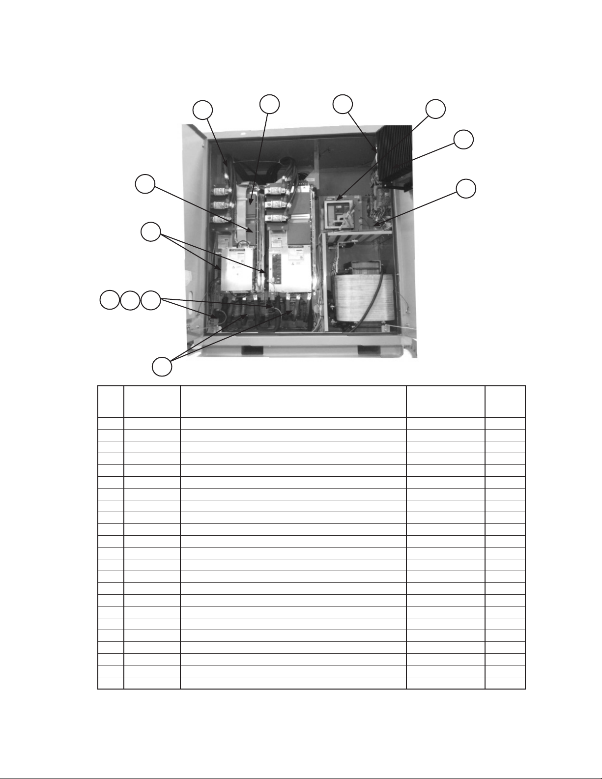
Controls
Main Control Box
Communication Card
Location
4
9
8
7
18
13
Ref. Schem.
No. Sym. Description Part No. Qty.
4 Board- Chiller I/O Backplane 300047099 1
7 CPU Board- Chiller Controller 300047102 1
N/S Connector, Chiller Controller, Beige 300048948 21
N/S Connector, Chiller Controller, Orange 300048949 4
8 Board- Digital I/O 333568101 1
9 Board- Analog Output 333568201 1
11 Board- IGV Stepper Motor 333568302 1
13 Board- Analog Input 333568401 2
18 SW5 Switch- Unit Enable 300047109 1
24 SW1 Switch- Unit and Compressor #1 300047110 2
N/S BAS BACnet MS/TP/E Installation Kit 2 332356961 1
N/S BAS Lonmark Installation Kit 2 332356952 1
N/S BAS Modbus Installation Kit 2 332356953 1
N/S= Not Shown on Diagram.
2
Includes the Communication Card and Installation Manual.
11
WME1500DB- Water Cooled Chiller New 09/15 RPL 7000517 / Page 11
Page 12
Controls
VFD Enclosure
5C
5B
3
4
5A
1
13
8
7
10
6
Ref. Schem.
No. Sym. Description Part No. Qty.
1 Fan 120 VAC 600 CFM 300047091 2
3 VFD1 VFD Chassis Assembly- Phases 1- 3 1 300047093 1
4 Fuse 20A/1000VAC 300047094 2
5A Valve- Solenoid 331796001 2
5B Valve- Coil 120/60, 10 watt 331796051 2
5C Repair Kit- Solenoid Valve 300052079 2
6 LR Line Reactor 3PH 300047096 2
7 IPS Intermediate Power Supply 300047097 1
8 MCB CBKR Molded Case 25KAIC 600V 400A 300048927 1
CBKR Molded Case 25KAIC 600V 600A 300048929 1
CBKR Molded Case 35KAIC 480V 500A 300047098 1
CBKR Molded Case 35KAIC 600V 500A 300047071 1
CBKR Molded Case 35KAIC 600V 600A 300047100 1
CBKR Molded Case 35KAIC 600V 800A 300048924 1
CBKR Molded Case 50KAIC 600V 400A 300048928 1
CBKR Molded Case 50KAIC 600V 600A 300048930 1
CBKR Molded Case 65KAIC 600V 500A 300047088 1
CBKR Molded Case 65KAIC 600V 600A 300047108 1
CBKR Molded Case 65KAIC 600V 800A 300048925 1
CBKR Molded Case 100KAIC 480V 400A 300047069 1
CBKR Molded Case 100KAIC 480V 600A 300048923 1
CBKR Molded Case 100KAIC 480V 800A 300048926 1
10 Surge Suppressor 480V 300047076 1
1
Refer to VFD Chassis Assembly detail on the following pages.
2
Quantity per VFD Enclosure.
2
WME1500DB- Water Cooled Chiller New 09/15 RPL 7000517 / Page 12
Page 13
Controls
VFD Chassis- Diagrams
16
1
4
3
2
15
5
12
6
13
14
7
13
8
11
WME1500DB- Water Cooled Chiller New 09/15 RPL 7000517 / Page 13
10
15
9
Page 14
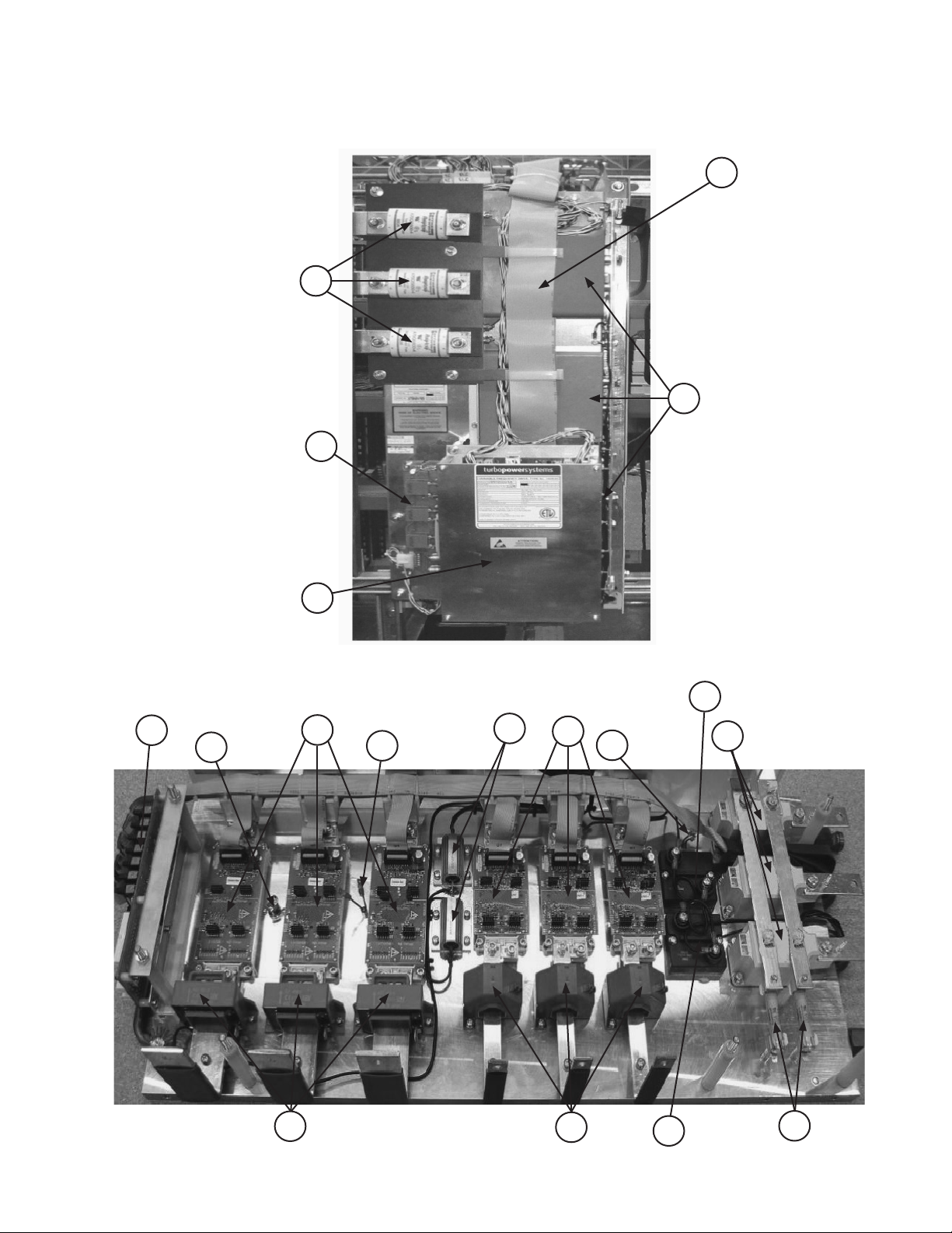
Controls
VFD Chassis- Components & Compressor Wiring Harness
VFD Chassis- Components
Ref. Schem.
No. Sym. Description Part No. Qty.
1 Fuse 600A, 700V 300047092 3
2 VFD Controller Assembly 300048932 1
Backup Battery for VFD Controller 334295801 1
3 Voltage Transducer Interface Board 300048950 1
4 Link Capacitor 1200uF, 700V 300048939 3
5 Connector Interface 300048934 1
6 Q4- 6 Steering Bridge IGBT Assy. 300048937 3
7 Q1- 3 Chopper IGBT Assy. 300048936 3
8 TDM1- 3 Diode Thyristor Module 300049088 3
9 Fuse 20A, 800V 300048941 2
10 CT1- 3 Current Transducer 300048942 3
11 CT4- 6 Current Transducer 300048943 3
12 TS1 Thermal Switch 300048945 1
13 TH1, 2 Thermistor 300048944 2
14 R3, 4 Resistor 2K2, 75W 300049089 2
15 R1, 2 Resistor 150R, 250W 300048938 2
16 Wire Harness/Cable Kit 2 300055446 1
N/S L1- 3 Chopper Chokes/Inductors 300048952 3
N/S Thyristor Driver Board 300048933 1
N/S Snubber Board 300048935 1
N/S Snubber Capacitors 1uF, 1200V 300048940 6
N/S D1 Diode 300048951 1
N/S= Not Shown on Diagram.
1
Quantity PER Chassis Assembly
2
Kit contains ribbon cables and harnesses. Connections include: Q1-J10; Q2-J11; Q3-J12; Q4-J7; Q5-J8; Q6-J9; J1-J6;
and J1-J14.
1
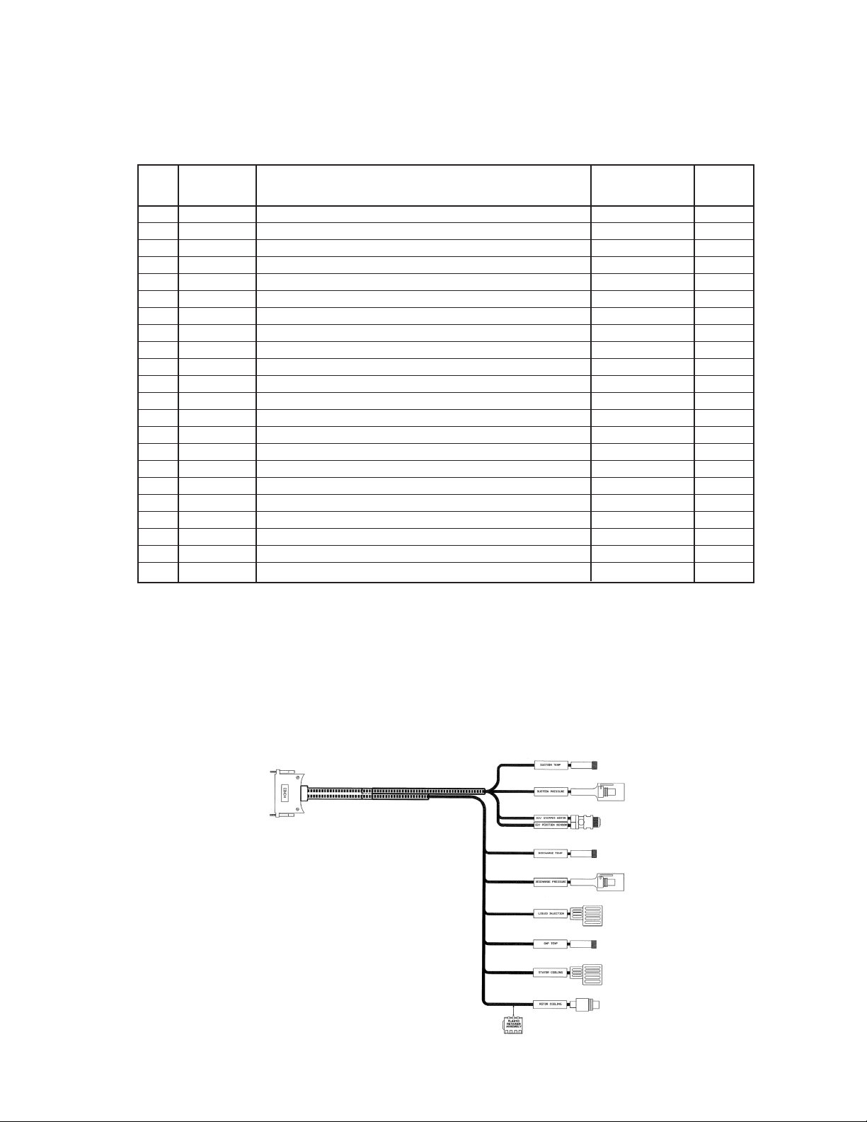
Compressor Wiring Harness
Part Number 331795503
Available as a complete assembly only. One per compressor.
WME1500DB- Water Cooled Chiller New 09/15 RPL 7000517 / Page 14
Page 15
Controls
VFD Power Supply Plate- Diagram
21
20
19
11
22
12
7
4
8
6
9
5
13
13
14
2
3
18
17
15
14
16
WME1500DB- Water Cooled Chiller New 09/15 RPL 7000517 / Page 15
Page 16
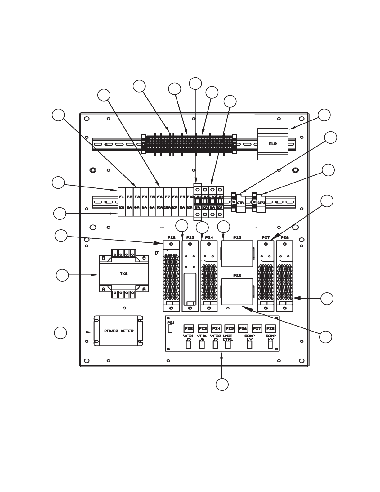
Controls
VFD Power Supply Plate- Components
Ref. Schem.
No. Sym. Description Part No. Qty.
2 Plate- Partition Gray 300047073 17
3 Terminal Block Gray 300047074 36
4 Terminal Block- Ground Green-Yellow 300047075 9
5 Bracket- End, Snap on 300047190 7
6 ELR Relay- Earth Leakage 300047078 1
7 CB1 Circuit Breaker- Primary 8A 300047079 1
8 CB2- 4 Circuit Breaker- 2 Fans & MCB trip 2A 300047080 3
9 Switch- Fan Failure 331578601 2
11 DC power supply +15 VDC 100 watts 300047081 1
12 DC power supply 15 VDC 25 watts 300047082 1
13 DC power supply +24 VDC 77 watts 300047083 2
14 DC power supply +24 VDC 100 watts 300047084 2
15 DC power supply +12 VDC 72 watts 300047085 1
16 DC Distribution Board 300047086 1
17 PM Monitor- Voltage, Power and Current 300047087 1
18 TX2 Transformer 480/240/120V 500VA 349939804 1
19 F1- 10 Fuse holder 300047088 7
20 F1-2, F8-10 Fuse 300047089 2
21 F3- 5 Fuse 300047090 3
22 F6-7 Fuse 300046902 2
1
Quantity per VFD Power Supply Plate.
1
WME1500DB- Water Cooled Chiller New 09/15 RPL 7000517 / Page 16
Page 17

Controls
OITS- Operator Interface Touch Screen
Swivel Bracket
15
Swivel Pins
1
1
Main Control Box
18
16
Ref.No. Description Part No. Qty.
15 Monitor- 15" LCD Touchscreen, Black 330276502 1
16 LCD Support Arm Assembly, Black 1 330815411 1
18 OITS/Unit Control Box Support Block 330406501 2
1
The LCD Support Arm Assembly includes the Swivel Bracket, the Swivel Pins, and the mounting hardware (screws, washers and
nuts). These items are not available separately.
WME1500DB- Water Cooled Chiller New 09/15 RPL 7000517 / Page 17
Page 18

Top View
Front View
S07
Control Sensors
Sensor Location Diagrams
S15
S14
S10
S13
S12
S11
End View
S02
S01
S04
S09
Out
In
Evaporator
Condenser
Out
In
S06
S05
S08
WME1500DB- Water Cooled Chiller New 09/15 RPL 7000517 / Page 18
Page 19
Control Sensors
Components
Ref. Description Part Qty.
No. Number
S01 Sensor- Evaporator Entering Water Temperature 073007203 1
S02 Sensor- Evaporator Leaving Water Temperature 073007203 1
S04 Switch- Evaporator Entering Flow 331796201 1
N/S Cable- Evaporator Entering Flow Switch (5 Meter Lg.) 330571403 1
S05 Sensor- Condenser Entering Water Temperature 073007203 1
S06 Sensor- Condenser Leaving Water Temperature 073007203 1
S07 Sensor- Condenser Refrigerant Pressure 071568621 1
S08 Switch- Condenser Entering Flow 331796201 1
N/S Cable- Condenser Entering Flow Switch (5 Meter Lg.) 330571403 1
S09 Sensor- Liquid Line Temperature 073007203 1
S10 Sensor- Compressor Suction Temperature 331582801 2 2
S11 Sensor- Compressor Suction Pressure 071568521 2
N/S Cable- Compressor Suction Pressure Sensor 331796801 2
S12 Sensor- Compressor Discharge Temperature 331582801 2 2
S13 Sensor- Compressor Discharge Pressure 071568621 2 2
S14 Sensor- Motor Gap Temperature 331795205 2 2
S15 Switch- High Pressure 074796301 2
N/S= Not Shown on Diagram
2
The Cable for this Sensor is part of the Compressor Wiring Harness and is not available separately. Refer to the Compressor Wiring
Harness section.
WME1500DB- Water Cooled Chiller New 09/15 RPL 7000517 / Page 19
Page 20

Compressor
Motor/Bearing Assemblies
Part No. Description Application Voltage
333507101 MBAW6/6 (Code 05= M4) 380 - 575V
Note: The Compressor Magnetic Bearing, Rotor, and Stator components are not eld
replaceable. If replacement is required, the entire assembly must be replaced. For
Compressor Motor/Bearing Assembly eld serviceable components see the following
page.
WME1500DB- Water Cooled Chiller New 09/15 RPL 7000517 / Page 20
Page 21

Compressor
Motor/Bearing Assembly Components
1
6
2
8A
8B
Front View Bottom View
11
Back View
Ref.
No. Description Part No. Qty.
1 Kit- Electronics Cover Assy. 1 300047066 1
2 Controller- Compressor 300047067 1
6 Kit- Electronics Cover Gasket 2 300047068 1
8A Kit- Connector Plate with Gasket 300047070 1
8B Kit- Connector Plate with Gasket & 3 Cables 300047070 1
11 Plug- Hex Head 300047072 1
1
Kit includes Cover, Gasket & Insulator.
2
Kit includes Gasket & Insulator. Included in Electronics Cover Assy Kit 300047066.
3
Quantity per Motor/Bearing Assembly.
3
WME1500DB- Water Cooled Chiller New 09/15 RPL 7000517 / Page 21
Page 22

407
Compressor
Impeller Assembly
402
403
405
404
406
418
416
417
415
Ref.
No. Description Part No. Qty.
402 Washer- Impeller 735043467 1
403- 406 Kit- Shim Washers, Impeller 1 300049084 1
407 Impeller Assembly 2 331347211 1
415 Volute Insert 331439602 1
416 Pin- Volute Insert .50 x .09" 735038039 1
417 O-Ring 3 330198639 1
418 Ring- Retaining 331438804 1
4
1
The shim combination is unique to each compressor. The kit contains quantities of four shim sizes.
2
Available as an assembly only.
3
Included in Compressor O-Ring Kit p/n 300049073. One kit per Compressor.
4
Quantity per Impeller Assembly.
WME1500DB- Water Cooled Chiller New 09/15 RPL 7000517 / Page 22
Page 23

Impeller Seal & Compressor Fittings- Diagrams
See Compressor
Inlet Assembly
Compressor
506
504
502
503
609
608
602
605
606
WME1500DB- Water Cooled Chiller New 09/15 RPL 7000517 / Page 23
607
Page 24

Compressor
Impeller Seal & Compressor Fittings- Components
Ref.
No. Description Part No. Qty.
502 Seal- Impeller (1 pair) 332027502 1
503 O-Ring 3 070194967 1
504 O-Ring 3 070194999 1
506 Screw, Stainless Steel 3/8-16 x 2.0" 331353705 24
602 Fitting- Elbow 2 332471617 1
O-Ring, ORFS 1 070194968 1
O-Ring, SAE 1 070194980 1
605 Fitting- Elbow 070789307 1
O-Ring, ORFS 1 735073650 1
O-Ring, SAE 1 735073625 1
606 Fitting- Elbow 070789368 1
O-Ring, ORFS 1 735073640 1
O-Ring, SAE 1 735073625 1
607 Fitting- Straight 070789383 1
O-Ring, ORFS 1 300047193 1
O-Ring, SAE 1 070194970 1
608 Fitting- Run Tee 070789392 1
O-Ring, ORFS 1 070194968 2
O-Ring, SAE 1 070194980 1
609 Well, Temperature Sensor 331795204 1
1
O-Ring(s) are furnished standard with all ttings. Order additional O-Rings if needed. ORFS Style
O-Rings seat on the face end of the tting. SAE style O-Rings seat at the base of the tting.
2
The well for this tting is integrated into the Discharge Housing and is not available separately.
3
Included in Compressor O-Ring Kit p/n 300049073. One kit per Compressor.
4
Quantity per Compressor.
4
WME1500DB- Water Cooled Chiller New 09/15 RPL 7000517 / Page 24
Page 25

315
307
313
311
Compressor
Discharge Housing & High Speed Shaft Seal
316
507
304
306
307
312
314
508
302
303
305
Ref.
No. Description Part No. Qty.
302 Discharge Housing 331553803 1
303 O-Ring 2 070194978 1
304 Screw, Stainless Steel #.38-16 x 2.0" 331353705 12
305 Screw, Stainless Steel #.38-16 x 3.0" 331353706 6
306 Ring- Liquid Injection 331552901 1
307 Screw #10 x .50" 735034921 12
311 Pin .50 x .09" 735038039 1
312 Seal- High Speed Shaft 1.5" 331351101 1
313 Shim- High Speed Shaft Seal 331347501 1
314 Spring- Wave, High Speed Shaft 735049886 1
315 Retainer- High Speed Shaft Seal 331353301 1
316 Pin- Locator 331584501 1
415 Dowel .25 x .875 735038038 1
416 Plug 735017102 1
O-Ring, SAE 1 735073623 1
507 Well, Temp Sensor 331582701 1
508 Valve- Access 070229306 1
1
O-Ring(s) are furnished standard with all ttings. Order additional O-Rings if needed.
2
Included in Compressor O-Ring Kit p/n 300049073. One kit per Compressor.
3
Quantity per Compressor.
415
416
3
WME1500DB- Water Cooled Chiller New 09/15 RPL 7000517 / Page 25
Page 26

Compressor
Inlet Assembly- Diagrams
201
201
202
206
203
204
205
213
210
211
212
220
221
222
219
218
207
209
208
WME1500DB- Water Cooled Chiller New 09/15 RPL 7000517 / Page 26
Page 27

Compressor
Inlet Assembly- Components
Ref. Description Part
No. Number Qty.
Complete Compressor Inlet Assembly 331553412 1
201 Inlet Housing 331587903 1
202 Gear- Face 331553201 1
203 Inlet Vane 331553002 11
204 Gear- Spur 331438202 11
205 Pin- Spur Gear .313 x .58" 735038065 11
206 Ring- Retaining Spur Gear 735049890 11
207 IGV Actuator Assembly, Complete 331583401 1
208 O-Ring 1 070194996 2
209 Screw- Stainless Steel .50-13 x 1.50" 331353704 2
210 Plug- Sensor Magnet 331438401 1
211 Magnet 331353802 1
212 Sensor 331352831 1
213 Bracket- Sensor 331352701 1
218 Ring- Vane Stop 331553301 1
219 Ring- Retaining Vane Stop 331438805 1
220 Valve- Access 070229306 1
221 Connector- Male 8 Pole 331795401 1
222 Well- Temperature Sensor 331582701 1
1
Included in Compressor O-Ring Kit p/n 300049073. One kit per Compressor.
2
Quantity per Inlet Assembly.
2
WME1500DB- Water Cooled Chiller New 09/15 RPL 7000517 / Page 27
Page 28

020
Unit Assembly
Relief & Shutoff Valves- Diagrams
022
024
021
081
082
080
083
WME1500DB- Water Cooled Chiller New 09/15 RPL 7000517 / Page 28
020
Page 29

Unit Assembly
Relief & Shutoff Valves- Components
Ref.
No. Description Part No. Qty.
020 Fitting- 90 Degree Elbow 332471635 3
O-Ring 1 070194963 3
021 Valve- Shut Off (on Condenser) 735039964 1
O-Ring, SAE 1 070194980 1
022 Valve- Relief (on Evaporator) 200# 735045817 2
024 Valve- Relief (on Condenser) 225# 735045829 2
080 Valve- Angle 332471701 2
O-Ring, ORFS 1 735043662 2
O-Ring, SAE 1 735073624 2
081 Cap- Tube End 070789347 2
082 Fitting 735043925 2
083 Fitting- Swivel 735043954 2
1
O-Ring(s) are furnished standard with all ttings. Order additional O-Rings if needed. ORFS Style O-Rings seat on the
face end of the tting. SAE style O-Rings seat at the base of the tting.
WME1500DB- Water Cooled Chiller New 09/15 RPL 7000517 / Page 29
Page 30

Unit Assembly
Discharge Piping Stack
See Suction Piping
136
135
126
132
022 147
127
022 128
125 126
Qty.=2
Ref.
No. Description Part No. Qty.
022 Nut 735029626 24
125 Valve- Check 8.0" 333283103 1
126 Gasket 070199040 3
127 Weld Flange 735031835 2
128 Screw .75 x 8.5" 735034137 8
132 Elbow- 90 Degree 8.0" 331554301 1
135 Nozzle- Discharge 331553702 1
136 O-Ring 330198643 1
147 Bolt 3/4-10 x 3.25" 735033966 8
1
Quantity per Discharge Piping Stack.
1
WME1500DB- Water Cooled Chiller New 09/15 RPL 7000517 / Page 30
Page 31

Unit Assembly
Range Extension
024
026
022
020
034
004
003
002
020
022
024
026
WME1500DB- Water Cooled Chiller New 09/15 RPL 7000517 / Page 31
Page 32

Unit Assembly
Range Extension
Ref.
No. Description Part No. Qty.
002 Core- Schrader Valve 026541100 4
003 Valve- Schrader 071100801 4
004 Cap- Schrader Valve 032943500 4
020 Kit- Flange 2 735016403 4
022 Adapter 735049702 4
024 Gasket- Flange 070199112 4
026 Screw- Flange .62 x 2.50" 735033864 16
034 Valve- Expansion 250T 330386205 2
Motor- Expansion Valve 330386209 2
Sight Glass- Expansion Valve 300043182 2
2
The Flange Kit does NOT contain a gasket. If a gasket is required, order Ref # 024 p/n 070199112.
Also, DO NOT use the screws that come with this Flange Kit. If screws are required, order 4pc. of
Ref # 026 p/n 735033864.
WME1500DB- Water Cooled Chiller New 09/15 RPL 7000517 / Page 32
Page 33

084
088
086
085
087
Unit Assembly
Suction and Discharge Piping
092
136
093
094
Ref.
No. Description Part No. Qty.
084 Screw M10- 1.5 x 50mm 735036546 18
085 Screw- Stainless Steel .38 -16 x 1.75" 331353707 12
086 Elbow- Suction 90 Degree 331352003 1
087 O-Ring 1 070194992 1
088 O-Ring 1 350233017 1
092 Screw .50 x 3.5" 735033967 8
093 Washer 040500313 8
094 Nut 735029626 8
136 O-Ring 330198643 1
1
Included in Compressor O-Ring Kit p/n 300049073. One kit per Compressor.
2
Quantity per Suction & Discharge Piping.
2
WME1500DB- Water Cooled Chiller New 09/15 RPL 7000517 / Page 33
Page 34

027
002
Unit Assembly
Liquid Injection
022
021
003
004
029
003
002
031
004
Ref.
No. Description Part No. Qty.
002 Core- Schrader Valve 026541100 2
003 Valve- Schrader 071100801 2
004 Cap- Schrader Valve 032943500 2
021 Fitting- ORFS to Braze Sleeve 070789351 1
O-Ring 1 070194968 1
022 Nut- Braze Sleeve 070789354 1
027 Valve- Solenoid .875" 735048473 1
N/S Coil- Solenoid Valve 24VDC 331796054 1
029 Strainer 735030501 1
031 Valve- Ball .875" 330286084 1
1
O-Ring(s) are furnished standard with each tting. Order additional O-Rings if needed.
2
Quantity per Liquid Injection Line.
2
WME1500DB- Water Cooled Chiller New 09/15 RPL 7000517 / Page 34
Page 35

Unit Assembly
Rotor Cooling
111
112
111
112
120
112
115
160
WME1500DB- Water Cooled Chiller New 09/15 RPL 7000517 / Page 35
Page 36

Unit Assembly
Rotor Cooling Components
Ref. Description Part
No. Number Qty.
111 Fitting- ORFS to Braze Sleeve 070789351 2
O-Ring 1 070194968 2
112 Nut- Braze Sleeve 070789354 3
115 Fitting- Reducer Sleeve 070789391 1
O-Ring 1 070194968 1
120 Valve- Solenoid 331796003 1
160 Valve- Ball .375" 330286001 1
1
O-Ring(s) are furnished standard with each tting. Order additional O-Rings if needed.
2
Quantity per Rotor Cooling Line.
2
WME1500DB- Water Cooled Chiller New 09/15 RPL 7000517 / Page 36
Page 37

Unit Assembly
Stator Cooling
023
026
022
020
028
029
045
002
004
Stator Cooling Return
003
036
045046
046
045
046
Stator Cooling Supply
003
002
004
WME1500DB- Water Cooled Chiller New 09/15 RPL 7000517 / Page 37
030
052
Page 38

Unit Assembly
Stator Cooling- Components
Ref. Description Part
No. Number Qty.
002 Core- Schrader Valve 026541100 2
003 Valve- Schrader 071100801 2
004 Cap- Schrader Valve 032943500 2
020 Fitting- Elbow ORFS to SAE 332471617 1
O-Ring, ORFS 1 070194968 1
O-Ring, SAE 1 070194980 1
022 Fitting- ORFS to Braze Sleeve 070789351 1
O-Ring 1 070194968 1
023 Nut- Braze Sleeve 070789354 1
026 Valve- Solenoid 331796002 1
N/S Coil- Solenoid Valve 24VDC 331796052 1
028 Fitting- Sleeve ORFS 070789361 1
O-Ring, ORFS 1 735073640 1
029 Fitting- Nut 070789360 1
030 Filter Drier 735028828 1
036 Valve- Ball .625" 330286003 1
045 Fitting- ORFS to Braze Sleeve 070789316 3
O-Ring, ORFS 1 735073650 3
046 Fitting- Nut ORFS 070789310 3
O-Ring, ORFS 1 735073650 3
052 Valve- Ball .875" 330286084 1
1
O-Ring(s) are furnished standard with each tting. Order additional O-Rings if needed. ORFS Style
O-Rings seat on the face end of the tting. SAE style O-Rings seat at the base of the tting.
2
Quantity per Stator Cooling Line.
2
WME1500DB- Water Cooled Chiller New 09/15 RPL 7000517 / Page 38
Page 39

Unit Assembly
VFD Cooling
031
021 022
003 004
002
VFD Cooling Return
031
003 004
002
012
002
003 004
021 022
021 022
002
003
004
002
003
004
VFD Cooling Supply
021 022
031
018
012
002
003
004
WME1500DB- Water Cooled Chiller New 09/15 RPL 7000517 / Page 39
Page 40

Unit Assembly
VFD Cooling
Ref. Description Part Qty.
No. Number
002 Core- Schrader Valve 026541100 6
003 Valve- Schrader 071100801 6
004 Cap- Schrader Valve 032943500 6
012 Valve- Ball 1.375" 330286086 4
018 Strainer 1.375" 735030536 2
021 Fitting- ORFS to Braze Sleeve 070789351 4
O-Ring 1 070194968 2
022 Nut- Braze Sleeve 070789354 4
031 Valve, Ball .875 330286084 4
1
O-Ring(s) are furnished standard with each tting. Order additional O-Rings if needed.
WME1500DB- Water Cooled Chiller New 09/15 RPL 7000517 / Page 40
Page 41

Unit Assembly
Liquid Line- Diagrams
060B
060A
060E
060D
060C
022
080
021
081
101
102
100
See
Expansion
Valve
section
022
020
024
WME1500DB- Water Cooled Chiller New 09/15 RPL 7000517 / Page 41
104
021
Page 42
Unit Assembly
Liquid Line- Components
Ref. Description Part Qty.
No. Number
020 Coupling- Adapter 071901601 1
021 Flange 071992102 2
022 Gasket 735073403 2
024 Strainer 070977802 1
060A Saddle- Sight Glass 330743304 1
060B Cap- Sight Glass 330508701 1
060C Valve- Schrader 071100801 1
060D Core- Schrader Valve 026541100 1
060E Cap- Schrader Valve 032943500 1
080 Coupling Adapter 071900701 1
081 Bolt .625 x 3.25" 735033966 4
100 O-Ring 735073630 1
101 Screw .75 x 3.0" 735033878 4
102 Washer, Lock 048164816 4
104 Screw .75 x 3.5" 735033967 4
WME1500DB- Water Cooled Chiller New 09/15 RPL 7000517 / Page 42
Page 43

Unit Assembly
Expansion Valve
115
121
105
103
127
125
126
Ref. Description Part Qty.
No. Number
102 Bearing 735014129 2
103 Seal 735234327 1
105 Check Valve 735040316 1
112 Flex Coupling 332778402 1
115 Motor, Stepper/IGV 331353601 1
119 Site Glass (on Motor Cover) 015997816 1
121 O-Ring 735043639 1
125 Expansion Valve Body 332935601 1
126 Site Glass (on Body) 332674501 1
127 O-Ring (between Body and Base) 735073633 1
128 O-Ring (between Base and Motor Cover) 735043674 1
102
102
128
119
112
WME1500DB- Water Cooled Chiller New 09/15 RPL 7000517 / Page 43
Page 44
352
353 354
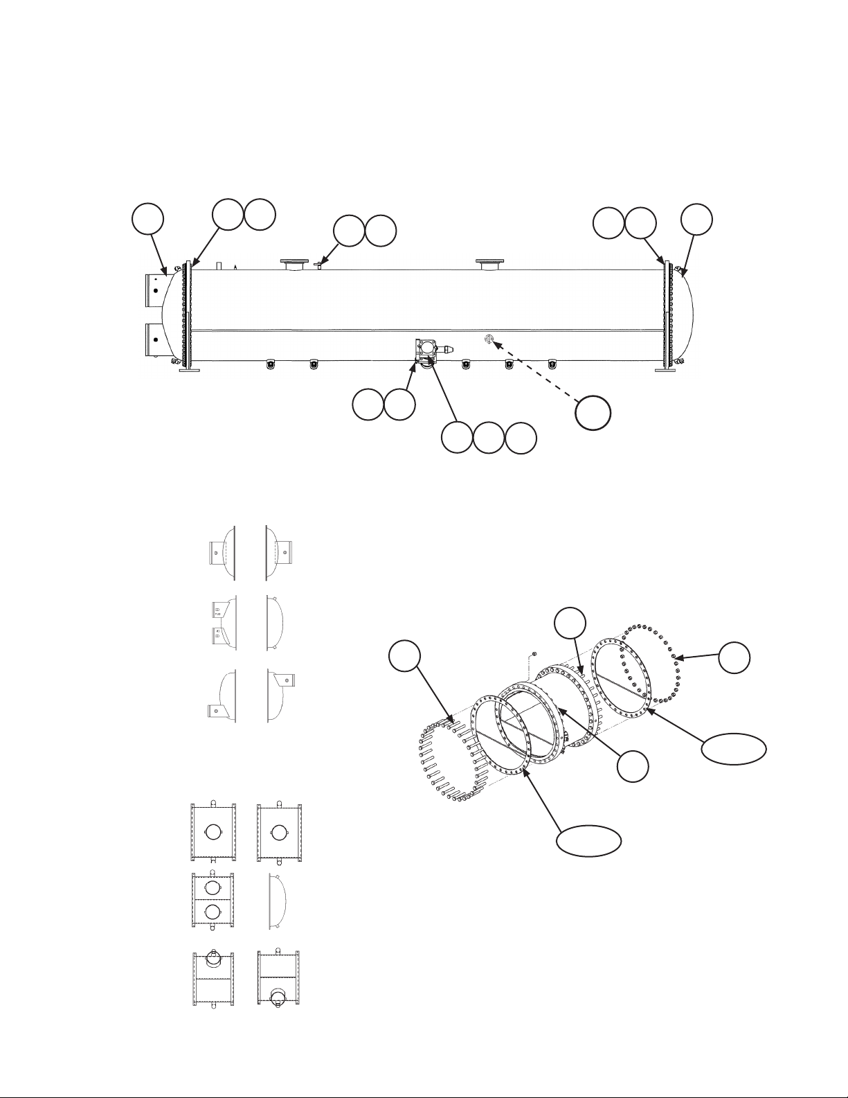
Condenser
Diagrams
2-Pass Condenser shown
Rear View
331330
353 354
355
Dish Head, Grooved
Entering
Return
1- Pass
2- Pass
3- Pass
Water Box Head, Grooved
Entering
Return
331330
Screw
353
251
252
110A
253
Water Box Head
Screw
353
(Located on the front side
of the Condenser)
Condenser End
354
Nut
352/355
354
Nut
Gasket
Cover End
1- Pass
352/355
Gasket
2- Pass
3- Pass
WME1500DB- Water Cooled Chiller New 09/15 RPL 7000517 / Page 44
Page 45

Condenser
42 Inch - Dish Head Gaskets & Hardware
150 PSIG non-ASME (Code 43=4)
Carbon Steel tube sheet and heads (Codes 46 & 47 = C)
1 Pass, Dish Heads
Ref. Description Part Quantity
No. Number
352/355 Gasket - Dish Head 334721707 2
353 Screw .75 x 3.5" 735033966 80 per head
354 Nut 735029626 80 per head
2 Pass, Dish Heads
Ref. Description Part Quantity
No. Number
352 Gasket - Dish Head, Entering Side 334825861 1
353 Screw .75 x 3.5" 735033966 80 per head
354 Nut 735029626 80 per head
355 Gasket- Dish Head, Return Side 334721707 1
3 Pass, Dish Heads
Ref. Description Part Quantity
No. Number
352/355 Gasket - Dish Head 334825861 2
353 Screw .75 x 3.5" 735033966 80 per head
354 Nut 735029626 80 per head
WME1500DB- Water Cooled Chiller New 09/15 RPL 7000517 / Page 45
Page 46
Condenser
42 Inch - Water Box Head Gaskets & Hardware
150 PSIG non-ASME (Code 43=4)
Carbon Steel tube sheet and heads (Codes 46 & 47 = C)
1-Pass, Water Box Heads with Top Nozzle (Code 40=D)
Ref. Description Part Quantity
No. Number
352/355 Gasket - Water Box Head 334721707 4
353 Screw .75 x 6.0" 735033972 80 x 4
354 Nut 735029626 80 x 4
1-Pass, Water Box Heads with Front Nozzle (Code 40=F)
Ref. Description Part Quantity
No. Number
352/355 Gasket - Water Box Head 334721707 4
353 Screw .75 x 6.0" 735033972 80 x 4
354 Nut 735029626 80 x 4
1
1
1
1
2-Pass, Water Box Heads with Front Nozzle (Code 40=J)
Ref. Description Part Quantity
No. Number
352 Gasket - Water Box Head, Entering Side 334825863 2
353 Screw for Water Box Head .75 x 6.0" 735033972 80 x 2
1
Screw for Dished Head .75 x 3.5" 735033966 56
354 Nut 735029626 80 x 3
1
355 Gasket- Dished Head, Return Side 334721707 1
3-Pass, Water Box Heads with Front Nozzle (Code 40=J)
Ref. Description Part Quantity
No. Number
352/355 Gasket - Water Box Head 334825863 4
353 Screw .75 x 6.0" 735033972 80 x 4
354 Nut 735029626 80 x 4
1
Each Water Box Head has 2 sets of screws and nuts. There are 80 screws + 80 nuts for the water box cover,
and 80 screws + 80 nuts at the connection of the head to the condenser. See Condenser diagrams.
1
1
WME1500DB- Water Cooled Chiller New 09/15 RPL 7000517 / Page 46
Page 47
Condenser
Sight Glass, Shut Off Valve & Gasket,
Charge Valve
Sight Glass, Shut Off Valve & Gasket, Charge Valve & Cap
Ref. Description Part Qty.
No. Number
110A Sight Glass 1.0" MPT 350229502 1
251 Valve- Shut Off (King Valve) 4.0" 735039809 1
252 Screw- Shut Off Valve .75 x 7.0 735033974 4
253 Gasket- Shut Off Valve 070199106 1
330 Valve- Charge 332480201 2
O-Ring for Charge Valve 735073634 2
331 Cap- Charge Valve 073243901 2
WME1500DB- Water Cooled Chiller New 09/15 RPL 7000517 / Page 47
Page 48

Evaporator
Diagrams
2-Pass Evaporator shown
Rear View
352
Dish Head, Grooved
353 354 353 354
Entering
1- Pass
Return
331330
110A
(Located on the front side
of the Evaporator)
Water Box Head
355
331330
2- Pass
3- Pass
Water Box Head, Grooved
Entering
Return
1- Pass
2- Pass
3- Pass
Screw
353
Cover end
Screw
353
352/355
Gasket
354
Nut
Condenser end
354
Nut
352/355
Gasket
WME1500DB- Water Cooled Chiller New 09/15 RPL 7000517 / Page 48
Page 49

Evaporator
48 Inch - Dish Head Gaskets & Hardware
150 PSIG non-ASME (Code 21=4)
Carbon Steel tube sheet and heads (Codes 24 & 25 = C)
1 Pass, Dish Heads
Ref. Description Part Quantity
No. Number
352/355 Gasket - Dish Head 334721708 2
353 Screw .75 x 3.5" 735033967 96 per head
354 Nut 735029626 96 per head
2 Pass, Dish Heads
Ref. Description Part Quantity
No. Number
352 Gasket - Dish Head, Entering Side 334825871 1
353 Screw .75 x 3.5" 735033967 96 per head
354 Nut 735029626 96 per head
355 Gasket- Return Head 334721708 1
3 Pass, Dish Heads
Ref. Description Part Quantity
No. Number
352/355 Gasket - Dish Head 334825871 2
353 Screw .75 x 3.5" 735033967 96 per head
354 Nut 735029626 96 per head
WME1500DB- Water Cooled Chiller New 09/15 RPL 7000517 / Page 49
Page 50

Evaporator
48 Inch - Water Box Head Gaskets & Hardware
150 PSIG non-ASME (Code 21=4)
Carbon Steel tube sheet and heads (Codes 24 & 25 = C)
1-Pass, Water Box Heads with Top Nozzle (Code 18=D)
Ref. Description Part Quantity
No. Number
352/355 Gasket - Water Box Head 334721708 4
353 Screw .75 x 6.5" 735033973 96 x 4
354 Nut 735029626 96 x 4
1-Pass, Water Box Heads with Rear Nozzle (Code 18=E)
Ref. Description Part Quantity
No. Number
352/355 Gasket - Water Box Head 334721708 4
353 Screw .75 x 6.5" 735033973 96 x 4
354 Nut 735029626 96 x 4
1
1
1
1
2-Pass, Water Box Heads with Rear Nozzle (Code 18=H)
Ref. Description Part Quantity
No. Number
352 Gasket - Water Box Head, Entering Side 334825872 2
353 Screw for Water Box Head .75 x 6.5" 735033973 96 x 2
1
Screw for Dished Head .75 x 3.5" 735033967 96
354 Nut 735029626 96 x 3
1
355 Gasket- Dished Head, Return Side 334721708 1
3-Pass, Water Box Heads with Rear Nozzle (Code 18=H)
Ref. Description Part Quantity
No. Number
352 Gasket - Water Box Head, Entering Side 334825872 2
355 Gasket - Water Box Head, Opposite Side 334825873 2
353 Screw .75 x 6.5" 735033973 96 x 4
354 Nut 735029626 96 x 4
1
Each Water Box Head has 2 sets of screws and nuts. There are 96 screws + 96 nuts for the water box cover,
and 96 screws + 96 nuts at the connection of the head to the evaporator. See Evaporator diagrams.
1
1
WME1500DB- Water Cooled Chiller New 09/15 RPL 7000517 / Page 50
Page 51
Evaporator
Sight Glass & Charge Valve
Sight Glass, Charge Valve & Cap
Ref. Description Part Qty.
No. Number
110A Sight Glass 1.0" MPT 350229502 1
330 Valve- Charge 332480201 2
O-Ring for Charge Valve 735073634 2
331 Cap- Charge Valve 073243901 2
WME1500DB- Water Cooled Chiller New 09/15 RPL 7000517 / Page 51
Page 52

Critical Daikin Applied OEM Parts
Are What Your HVAC Unit Needs!
Daikin MagnitudeTM Centrifugal Chiller
WME
1500
Critical Components UNIT SIZE Voltage Part Number
Sensors
S01 - Evap Entering Water Temp 1500 ALL 073007203
S02 - Evap Leaving Water Temp 1500 ALL 073007203
S05 - Cond Entering Water Temp 1500 ALL 073007203
S06 - Cond Leaving Water Temp 1500 ALL 073007203
S07 - Cond Refrigerant Pressure 1500 ALL 071568621
S09 - Liquid Line Temp 1500 ALL 073007203
S10 - Compr Suction Temp 1500 ALL 331582801
S11 - Compr Suction Pressure 1500 ALL 071568521
S12 - Compr Discharge Temp 1500 ALL 331582801
S13 - Compr Discharge Pressure 1500 ALL 071568621
S14 - Motor Gap Temp 1500 ALL 331795205
Switches
S04 - Switch, Evap Entering Flow 1500 ALL 331796201
S08 - Switch, Cond Entering Flow 1500 ALL 331796201
S15 - Switch, High Pressure 1500 ALL 074796301
VFD Controls
Wire Harness/Cable Kit 1500 ALL 300055446
Fuse, 20A/1000VAC 1500 ALL 300047094
Fuse, 600A/700V 1500 ALL 300047092
Fuse, 20A/800V 1500 ALL 300048941
Fuse, Power Supply Plate F1-2, F8-10 1500 ALL 300047089
Fuse, Power Supply Plate F3-5 1500 ALL 300047090
Fuse, Power Supply Plate F6-7 1500 ALL 300046902
Compressor O-Ring Kit
Compressor O-Ring Kit (one kit per compr) 1500 ALL 300049073
Call Your Local Daikin Applied Parts Distributor For All Your Parts Needs.
To Locate A Distributor, Go To www.DaikinApplied.com or Call 1-800-37PARTS
7000516 New 09/2015 CPL Page 1 of 1
 Loading...