

Page 1

Replacement Parts List No. 700005800
Revision F 9/2011
Water-Cooled Magnetic Bearing
Centrifugal Chiller
WMC
035T
To find your McQuay parts distributor, call 1-800-377-2787 or visit www.mcquay.com
Page 2

Contents
Parts List Revision History ....................................................................................................................... 3
Complete Model Nomenclature ..........................................................................................................4 - 5
Electrical Legend ..................................................................................................................................... 6
Unit Components ..................................................................................................................................... 7
Frictionless Compressor ..................................................................................................................... 8 - 9
Discharge Service Valve and Discharge Line Tubing ............................................................................ 10
Tubing - Suction Line ............................................................................................................................. 11
Tubing - Liquid Line and Liquid Injection Line ........................................................................................ 12
Condenser- Standard Heads .......................................................................................................... 13 - 14
Condenser- Water Box Heads ........................................................................................................15 - 16
Evaporator- Standard Heads ......................................................................................................... 17 - 18
Evaporator- Water Box Heads .......................................................................................................19 - 20
Insulation ............................................................................................................................................... 21
Unit Controls:
Operator Interface Panel .................................................................................................................. 22
Single Point Connection Box ...........................................................................................................23
Unit Control Box ........................................................................................................................24 - 26
Power Panels ............................................................................................................................ 27 - 30
Control Box Label ............................................................................................................................ 31
Magnetic Bearing Chiller; WMC 035T Rev. F 9/2011 RPL 700005800 / Page 2
Page 3
Parts List Revision History
Revision Date Description
NEW 06/2005 New
A 11/2005 Pages 17 & 18: Added part #s for items previously shown as To Be Determined.
B 11/2007 Page 5 - Added Compressor with p/n 330619043.
Ref #14 Change RLA to FLA.
C 12/08 Page 6 - Added Bub # 19 to drawing.
Page 7 - Ref. #5 add ‘Suction’ and Ref #6 add ‘Discharge’ to description.
Added Suction/Discharge Flange O’ Rings p/n 300042907 as Ref #19.
D 5/09 Page 7- Ref #19 change to “Suction/Discharge/Economizer Flange O-rings” and
change p/n to 300043968.
E 2/2010 Page 7 - Added IGBT Assembly.
Page 12 - Corrected Tube description.
Page 14 - Added part #s for Sensors that were TBD.
Page 19 - Added part #s for Cables that were TBD.
Pages 23-24 - Added footnote for items that were TBD.
F 9/2011 Pages 4 & 5: Added 2 pages to expand Model Nomenclature information.
Pages 7 thru 9 - Updated Compressor information.
Pages 13 thru 16 - Expanded information for Condenser Heads.
Pages 17 thru 20 - Expanded information for Evaporator Heads.
Page 21 - Changed note for Insulation.
Pages 22 thru 31: Re-structured and updated Control information.
13600 Industrial Park Blvd., P.O. Box 1551, Minneapolis, MN 55440 (763) 553-5330
Magnetic Bearing Chiller; WMC 035T Rev. F 9/2011 RPL 700005800 / Page 3
Page 4

Complete Model Nomenclature
Complete Model Nomenclature
WMC 035T TT 13R NN N A E2209 BE 2RA C4 0440 CC Y A C2009 BLYY 2RAYYY
Code 02 03 04 05 06 07 08 09 10 11 12 13 14 15 16 17 18
C4 1050 CCYY YY A A 134 124 EE 2LEYYA SMYDSYYS 0170 Y YY B
Code 19 20 21 22 23 24 25 26 27 28 29 30 31 32 33
02 Size (in nominal tons)
035T= 150 Tons, Dual Compressors
03 Unit Configuration
TT= Standard Compressor, Single Circuit
04 Voltage
13R= 460V / 60Hz
05 Always NN
06 Always N
07 Compressor Model Revision
A= Compressor Revision A
08 Evaporator
E2209= 22" Diameter, 9 ft. length
E2212= 22" Diameter, 12 ft. length
09 Evaporator Tubes
Digit 1
Tube Count
Digit 2
E= 0.025 wall, CU Turbo, EHP
10 Evaporator Heads
Digit 1
2= 2 Pass
Digit 2
R= Right Hand Inlet Nozzle
L= Left hand Inlet Nozzle
Digit 3
A= Standard Victaulic
B= Flanged
13 Evaporator Tube Sheet & Head Material
Digit 1
C= Carbon Steel Tube Sheet
Digit 2
C= Carbon Steel Heads
14 Always Y
15 Evaporator Model Revision
A= Evaporator Revision A
16 Condenser
C2009= 20" Diameter, 9 ft. length
C2012= 20" Diameter, 12 ft. length
17 Condenser Tubes
Digit 1
Tube Count
Digit 2
L= 0.025 wall, CU Turbo, CSL
Digits 3-4
Always YY
18 Condenser Heads
Digit 1
2= 2 Pass
3= 3 Pass
Digit 2
R= Right Hand Inlet Nozzle
L= Left hand Inlet Nozzle
Digit 3
A= Standard Victaulic
B= Flanged
Digits 4-6
Always YYY
11 Evaporator Design Pressure
Digit 1
C= 200 PSIG Refrigerant Side
Digit 2
1= 150 PSIG Waterside, ASME Code
2= 250 PSIG Waterside, ASME Code
3= 350 PSIG Waterside, ASME Code
4= 150 PSIG Waterside, non-ASME Code
5= 300 PSIG Waterside, non-ASME Code
12 Evaporator Leaving Water Temperature
Degrees Fahrenheit x 10
19 Condenser Design Pressure
Digit 1
C= 200 PSIG Refrigerant Side
Digit 2
1= 150 PSIG Waterside, ASME Code
2= 250 PSIG Waterside, ASME Code
3= 350 PSIG Waterside, ASME Code
4= 150 PSIG Waterside, non-ASME Code
5= 300 PSIG Waterside, non-ASME
20 Condenser Max Leaving Water Temperature
Degrees Fahrenheit x 10
Magnetic Bearing Chiller; WMC 035T Rev. F 9/2011 RPL 700005800 / Page 4
Page 5

Complete Model Nomenclature
21 Condenser Tube Sheet & Head Material
Digit 1
C= Carbon Steel Tube Sheet
Digit 2
C= Carbon Steel Heads
Digits 3-4
Always YY
22 Always YY
23 Condenser Model Revision
A= Condenser Revision A
24 Pressure Vessel Code
A= ASME
J= Australia ASME with documentation
P= Chinese
T= Taiwan ASME with documentation
1= CRN British Columbia
2= CRN Alberta
3= CRN Saskatchewan
4= CRN Manitoba
5= CRN Ontario
6= CRN Quebec
7= CRN New Brunswick
8= CRN Nova Scotia
9= CRN Prince Edward Island
0= CRN Newfoundland
U= CRN Yukon
25 Refrigerant
134= Refrigerant 134a
26 Refrigerant Weight
example: 124= 1240 lbs divided by 10
27 Expansion Valve
EE= Electronic Expansion Valve
29 Front End Box Options
Digit 1
S= Single Point
M= Multi-Point
Digit 2
M= Unit Mounted VFD
Digit 3
Y= Standard Filter
P= EMI Filter
Digit 4
D= Disconnect Switch
P= Power Block
Digit 5
Always S
Digit 6
Y= Standard Short Circuit Current Rating
Digit 7
Y= No Ground Fault Protection
F= With Ground Fault Protection
Digit 8
S= Standard Load Balance
30 Rated Load Amps
Compressor RLA
31 Always Y
32 Insulation
Digit 1
H= 3/4" insulation on Evap Shell, Suction Piping,
Compressor Inlet, Motor Barrel, plus High Humidity
3= 1-1/2" insulation on Evap shell; 3/4" insulation on
Suction Piping and Compressor Inlet
Y= No Shell Insulation
Digit 2
1= Return Head Insulation
2= Return and Connection Head Insulation
Y= No Head Insulation
28 Controls
Digit 1
2= Microtech II
Digit 2
L= Large Controller
Digit 3
E= English Language
Digit 4
Always Y
Digit 5
B= BACnet w/ RS485 and Ethernet
L= LonMark
M= ModBus
S= Serial Port w/RS232
Y= None
Digit 6
A= NEMA 1
33 Water Flow Indication
B= Water Flow Indicator on Evaporator and Condenser
Magnetic Bearing Chiller; WMC 035T Rev. F 9/2011 RPL 700005800 / Page 5
Page 6

Electrical Legend
A .................................... Alarm
B1-B10 ........................... Analog Input Connections
CAP ............................... Capacitor
CB .................................. Circuit Breaker
CBX ............................... Compressor Box
CC .................................Compressor Controller
CF .................................. Condenser Flow Switch
CO ................................. Compressor Off Relay
CP1 & CP2 .................... Condenser Pump Cycling Relay
CR .................................Compressor Relay
CT .................................. Control Transformer
CWI ................................ Condenser Water Interlocks
C1 .................................. Cooling Tower Fan Relay (Stage 1)
C2 .................................. Cooling Tower Fan Relay (Stage 2)
C3 .................................. Cooling Tower Fan Relay (Stage 3)
C4 .................................. Cooling Tower Fan Relay (Stage 4)
EF .................................. Evaporator Flow Switch
EP1 & 2 .........................Evaporator Pump Cycling Relay
EWI ................................ Evaporator Water Interlocks
EXV ...............................Electronic Expansion Valve
GDB ............................... Guardistor Board
GFP ............................... Ground Fault Protector
HG ................................. Hot Gas Solenoid
HR1 & 2 ......................... Heater Relay
ID1 thru 18 ..................... Digital Input Connections
IR2 thru 4 ....................... Isolation Relay for T2 thru T4
L1................................... Liquid Injection Solenoid
LR ......................................Latch Relay
MA .....................................Contactor Auxillary
MC ....................................Motor Cooling Solenoid
MCR ..................................Motor Contactor Relay (Starter)
MHP ..................................Mechanical High Pressure Switch
NO1-18, NC1-18 ................Digital Output Connections
OC .....................................Oil Cooler Solenoid (120 or 24 VAC)
OL .....................................Overload
OP ....................................Oil Pump Contactor
PTB ....................................Pressure Transducer Board
RL ......................................Reactor, Line Side
SA(Unload), SB(Load) .......Vane Control Solenoids
SC ......................................Signal Converter
SW1 ...................................Unit Start/Stop Switch
SW2 ...................................Compressor Manual Stop Switch
SW3 ...................................Remote Start/Stop Switch
SW4 ...................................Mode Switch
SW5 ...................................Emergency Stop Switch
T1 ......................................Transformer (120VAC)
T2 ......................................Transformer (24VAC)
T3 ......................................Transformer (24VAC)
T4 ......................................Transformer (24VAC)
T5 ......................................Transformer (24VAC) / Isolation
VC ......................................Vane Close Switch
VO .....................................Vane Open Switch
VR ......................................Voltage Relay
UC .....................................Unit Controller
Magnetic Bearing Chiller; WMC 035T Rev. F 9/2011 RPL 700005800 / Page 6
Page 7
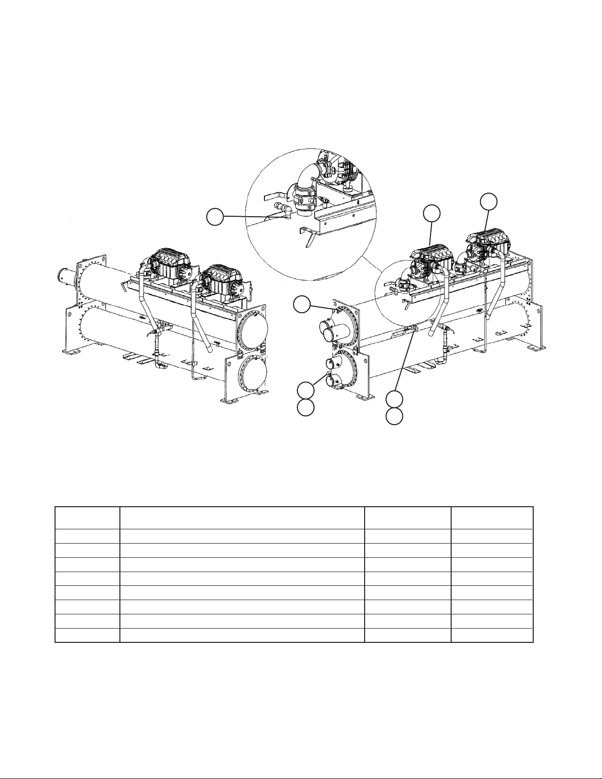
Unit Components
175
014
001
001
320
321
183
186
Ref. # Description Part Number Quantity
001 Compressor See Note 2
014 Mini Ball Valve 071596201 4
175 Relief Valve 200# 735045817 1
183 Shut Off Valve 735039977* 1
186 Relief Valve 200# 735045817 1
320 Flow Sensor 330571401 2
321 Cable, Flow Sensor, 5 meters 330571402 2
Note: Contact McQuay Parts with the compressor model, compressor part number, compressor serial number and BMCC
revision. On dual compressor units, provide same information on other compressor to ensure BMCC compatibility.
* Can use Valve 735039964 and Pipe Nipple 735031797 in place of this valve, if needed.
Magnetic Bearing Chiller; WMC 035T Rev. F 9/2011 RPL 700005800 / Page 7
Page 8
009
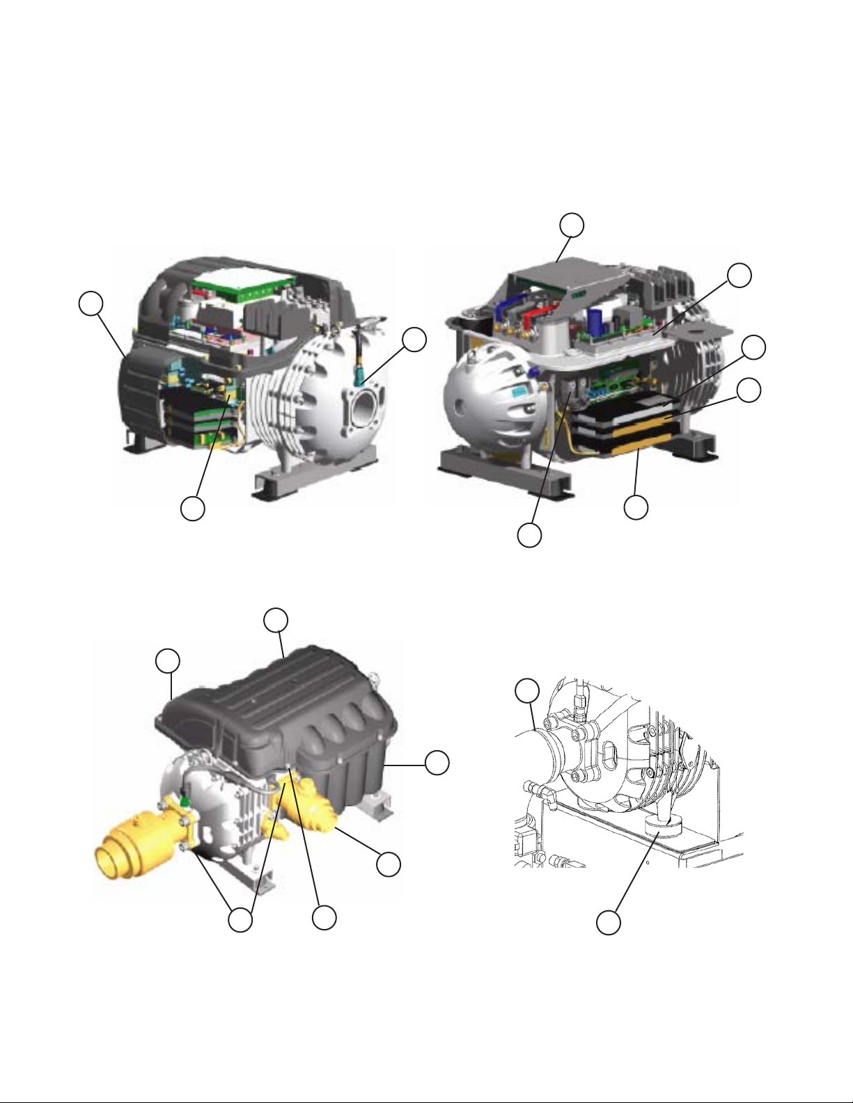
Frictionless Compressor
013
003
010
004
008
005
012
014
002
015
018
011
018
019
006
016
Compressor Isolator
Magnetic Bearing Chiller; WMC 035T Rev. F 9/2011 RPL 700005800 / Page 8
Page 9
Frictionless Compressor
Quantity
Ref. # Description Part Number per compressor
2 Kit, Module, Bearing PVM 300040127 1
3 Kit, Module, DC-DC Converter 300042897 1
4 Kit, Module, Backplane Assy 300042899 1
5 Pressure Sensor, Suction 150 PSI 300040130 1
6 Pressure Sensor, Discharge 300 PSI 300040131 1
8 Kit, Cover, Top Assy 300040136 1
9 Kit, Cover, Service Side Assy 300040137 1
10 Kit, Cover, Power (Mains) Inlet 300040138 1
11 Kit, Cover, Capacitor Assy 300040139 1
12 Kit, Module, Serial Driver 300043064 1
13 Kit, Module, Soft Start 300043245 1
14 BMCC See Note 1
15 Kit, Solenoid Valve 300040132 1
16 Compressor Isolator, Neoprene 330527701 4
18 Compressor Discharge Service Valve, with gasket See next page 1
3
19 Kit, O-Ring, Ports Connection
NS Sensor, Cavity Temperature 300042906 1
NS Kit, O-Ring 300042907 1
NS IGBT Assembly 300040931 1
NS Kit, O-Ring, IGBT Assy 300043869 1
300043968 1
Note: Contact McQuay Parts with the compressor model, compressor part number, compressor serial number and BMCC
revision. On dual compressor units, provide same information on other compressor to ensure BMCC compatibility.
3
Includes O-Rings for Suction, Discharge and Economizer Ports.
NS = Not Shown
Magnetic Bearing Chiller; WMC 035T Rev. F 9/2011 RPL 700005800 / Page 9
Page 10
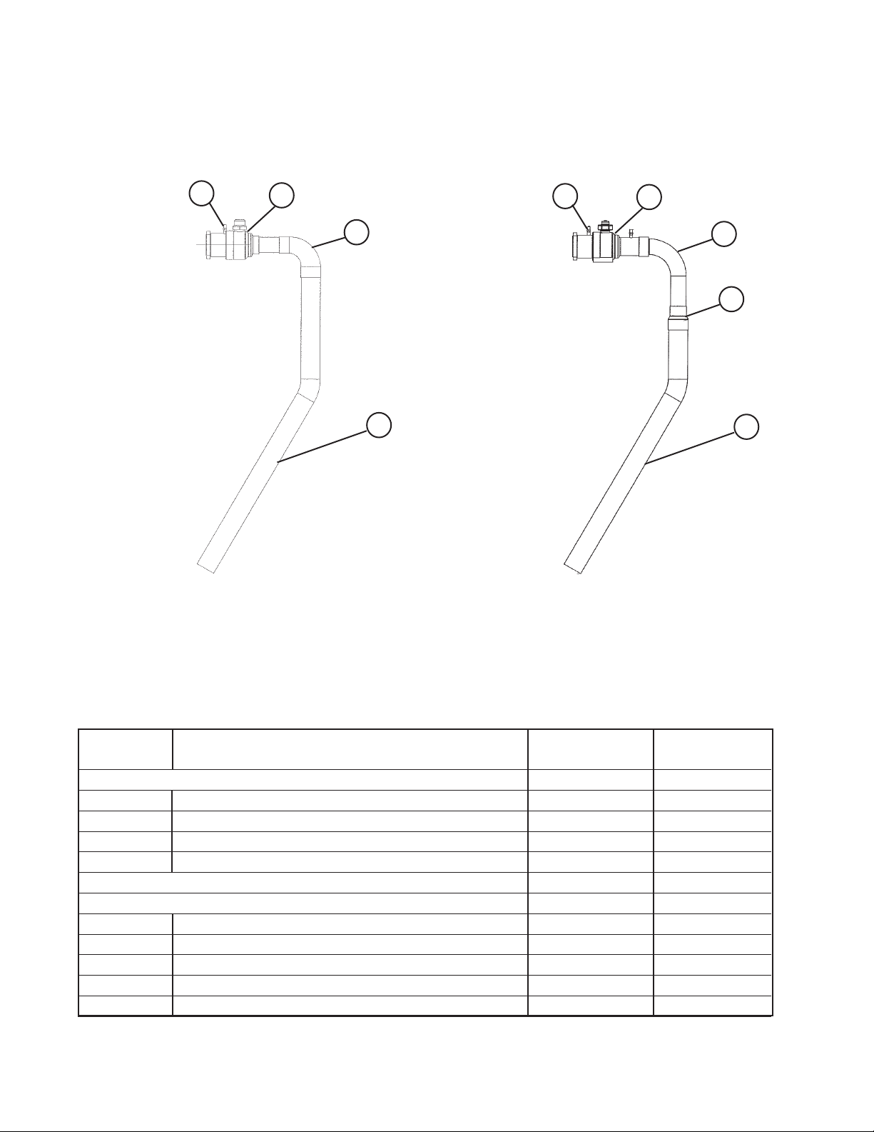
Discharge Service Valve and Discharge Line Tubing
D03
018
Original Configuration
Valve has straight end.
Elbow on outside of Valve.
D02
D01
D03
018
New Configuration
Valve has bell end.
Elbow on inside of Valve.
D02
D04
D01
See above diagrams to determine which configuration is on unit. Can use either Discharge Service Valve as long
as all corresponding components are also used. If going from Original to New, can cut existing Discharge Tube
(D01) to fit new configuration.
Quantity
Ref. # Description Part Number per circuit
Original Configuration
018 Discharge Service Valve, with gasket 330619002 1
D01 Discharge Tube 330653801 1
D02 Elbow 041120810 1
D03 Valve 047135502 2
New Configuration
018 Discharge Service Valve, with gasket 330619004 1
D01 Discharge Tube 330653802 1
D02 Elbow 331341601 1
D03 Valve 047135502 2
D04 Coupling Reducer 041116534 1
Magnetic Bearing Chiller; WMC 035T Rev. F 9/2011 RPL 700005800 / Page 10
Page 11

Tubing - Suction Line
S01
S04
S06
Quantity
Ref. # Description Part Number per circuit
S01 Flange, Compressor Suction 330427001 1
S04 Shutoff Valve 330342706 1
S06 Relief Valve, 200#, Angle 735045818 1
Magnetic Bearing Chiller; WMC 035T Rev. F 9/2011 RPL 700005800 / Page 11
Page 12

Tubing - Liquid Line and Liquid Injection Line
L53
L04
L04
L54
L55
L68
L02
L02
L54
L55
L68
Liquid Line - 12 ft. vessels Liquid Line - 9 ft. vessels
L54
L55
L68
L53
L54
L55
L68
L53
L57
Liquid Injection Line
Quantity
Ref. # Description Part Number per line
L02 Ball Valve 330286057 1
L04 Electronic Expansion Valve 330386201 1
L53 Ball Valve 330286053 3
L54 Schrader Valve 071100801 3*
L55 Valve Core 026541100 3*
L57 Filter Drier 735028827 1
L68 Valve Cap, Brass 032943500 3*
* One per Liquid Line, two per Liquid Injection Line.
Magnetic Bearing Chiller; WMC 035T Rev. F 9/2011 RPL 700005800 / Page 12
Page 13

Condenser- Standard Heads
Head
Gasket
351
352
Connection
End
331
330
110
Return
2-Pass, Left-Hand, Std. Victaulic (Front View)
Ref. # Description Part Number Qty.
110 Sight Glass Clear w/Ball 350229501 1
330 Shut-Off Valve 735039929 2
331 Cap, Flare 073243901 2
End
355
350
Gasket
Head
Code 18: 1 L A YYY
# Passes Connection Heads Future Use
2=2 Pass L= Left Hand A= Std. Victaulic
3=3 Pass R= Right Hand
Head Types
Standard Victaulic
Connection
Return
2- Pass
3- Pass
Magnetic Bearing Chiller; WMC 035T Rev. F 9/2011 RPL 700005800 / Page 13
Page 14

Condenser- Standard Heads
150 PSI Standard Heads, Victaulic - 2 Pass, non-ASME
Ref. # Description Part Number Qty.
350 Assy, Return Head 350290102 1
351 Assembly, Connection Head 331064112 1
352 Gasket, Connection Head 071557803K 1
355 Gasket, Return Head 070304644 1
NS Screw, H5, 0.50 x 2.5 735033851 22 per head
NS Nut, 0.50-13 735029625 22 per head
NS = Not Shown
150 PSI Standard Heads, Victaulic - 2 Pass, ASME
Ref. # Description Part Number Qty.
350 Assembly, Return Head 074188912 1
351 Assembly, Connection Head 074188913 1
352 Gasket, Connection Head 071557803K 1
355 Gasket, Return Head 070304644 1
NS Screw, H8, 0.50 x 4.0 735033542 22 per head
NS Nut, 0.50-13 735029629 22 per head
NS = Not Shown
150 PSI Standard Heads, Victaulic - 3 Pass, non-ASME
Ref. # Description Part Number Qty.
350 Assembly, Head, Outlet 331064132 1
351 Assembly, Head, Inlet 331064122 1
352/355 Gasket, Head 071557803K 2
NS Screw- H5, 0.50 x 2.5 735033851 22 per head
NS Nut- 0.50-13 735029625 22 per head
NS = Not Shown
Magnetic Bearing Chiller; WMC 035T Rev. F 9/2011 RPL 700005800 / Page 14
Page 15

Condenser- Water Box Heads
Head
366
Water Box
Cover Gasket
Gasket
351
352
Connection
End
331
330
330
110
Return
End
2-Pass, Left-Hand, Water Box Victaulic (Front View)
Ref. # Description Part Number Qty.
110 Sight Glass Clear w/Ball 350229501 1
330 Shut-Off Valve 735039929 2
331 Cap, Flare 073243901 2
355
350
Gasket
Head
Code 18: 1 L A YYY
# Passes Connection Heads Future Use
2=2 Pass L= Left Hand C= Wtr. Bx. Victaulic
3=3 Pass R= Right Hand D= Wtr. Bx. Flanged
Head Types
Water Box Victaulic Water Box Flanged
Connection
Return
Connection
Return
2- Pass
3- Pass
Magnetic Bearing Chiller; WMC 035T Rev. F 9/2011 RPL 700005800 / Page 15
Page 16

Condenser- Water Box Heads
150 PSI Water Box Heads, Victaulic and Flanged - 2 Pass, non-ASME
Ref. # Description Part Number Qty.
350 Assembly, Return Head 350290102 1
351 Assembly, Connection Head
with Flanged Connection 331231062 1
with Victaulic Connection 331064162 1
352 Gasket, Connection Head 071557853 1
355 Gasket, Return Head 070304644 1
366 Gasket, Water Box Cover 333850004 1
NS Screw- H5, 0.50 x 2.5, for Return Head 735033851 22 per head
NS Screw- H5, 0.50 x 4.0, for Water Box 735033942 44 per head
NS Nut- 0.50-13, for Return Head 735029625 22 per head
NS Nut- 0.50-13, for Water Box Head 735029625 44 per head
NS = Not Shown
150 PSI Water Box Heads, Flanged - 3 Pass, non-ASME
Ref. # Description Part Number Quantity
350 Assembly, Head, Inlet 331231064 1
351 Assembly, Head, Outlet 331231065 1
352/355 Gasket, Water Box connection to Condenser 071557854 2
366 Gasket, Water Box Cover 333850004 2
NS Screw- H5, 0.50 x 4.0, for Water Box 735033942 44 per head
NS Nut- 0.50-13 735029625 44 per head
NS = Not Shown
Magnetic Bearing Chiller; WMC 035T Rev. F 9/2011 RPL 700005800 / Page 16
Page 17

Evaporator- Standard Heads
Head
Gasket
351
352
Connection
End
330
331
330
331
110
2-Pass, Left-Hand, Standard Victaulic (Front View)
Return
End
355
350
Ref. # Description Part Number Qty.
110 Sight Glass Clear w/Ball 350229501 1
330 Shut-Off Valve 735039929 2
331 Cap, Flare 073243901 2
Gasket
Head
Code 10: 1 L A
# Passes Connection Heads
2=2 Pass L= Left Hand A= Std. Victaulic
3=3 Pass R= Right Hand B= Std. Flanged
Head Types
Standard Victaulic Standard Flanged
Connection
Return
Connection
Return
2- Pass
3- Pass
Magnetic Bearing Chiller; WMC 035T Rev. F 9/2011 RPL 700005800 / Page 17
Page 18

Evaporator- Standard Heads
150 PSI Standard Heads, Victaulic and Flanged - 2 Pass, non-ASME
Ref. # Description Part Number Qty.
350 Assembly, Return Head 332182902 1
351 Assembly, Connection Head
Flanged Connection 331065603 1
Victaulic Connection 331064903 1
352 Gasket, Connection Head 071557804K 1
355 Gasket, Return Head 070304645 1
NS Screw, H5, 0.50 x 2.5 735033851 26 per head
NS Nut, 0.50-13 735029625 26 per head
NS = Not Shown
150 PSI Standard Heads, Victaulic - 2 Pass, ASME
Ref. # Description Part Number Qty.
350 Assembly, Return Head 074380712 1
351 Assembly, Connection Head 331064913 1
352 Gasket, Connection Head 071557804K 1
355 Gasket, Return Head 070304645 1
NS Screw, H5, 0.50 x 4.0 735033942 26 per head
NS Nut, 0.50-13 735029625 26 per head
NS = Not Shown
150 PSI Standard Heads, Victaulic - 3 Pass, non-ASME
Ref. # Description Part Number Qty.
350/351 Assembly, Head, Inlet & Outlet 331064904 2
352/355 Gasket, Head 071557804K 2
NS Screw- H5, 0.50 x 2.5 735033851 26 per head
NS Nut- 0.50-13 735029625 26 per head
NS = Not Shown
300 PSI Standard Heads, Victaulic - 2 Pass, non-ASME
Ref. # Description Part Number Qty.
350 Assembly, Return Head 350290322 1
351 Assembly, Connection Head 331064923 1
352 Gasket, Connection Head 071557814 1
355 Gasket, Return Head 070304614 1
NS Screw, H5, 0.50 x 4.5 735033943 52 per head
NS Nut, 0.50-13 735029625 52 per head
NS = Not Shown
Magnetic Bearing Chiller; WMC 035T Rev. F 9/2011 RPL 700005800 / Page 18
Page 19

Evaporator- Water Box Heads
Water
Box
Cover
Gasket
Head
366
351
Gasket
Connection
End
352
330
331
330
331
110
Return
End
355
350
2-Pass, Left-Hand, Water Box Victaulic (Front View)
Ref. # Description Part Number Qty.
110 Sight Glass Clear w/Ball 350229501 1
330 Shut-Off Valve 735039929 2
331 Cap, Flare 073243901 2
Gasket
Head
Code 10: 1 L A
# Passes Connection Heads
2=2 Pass L= Left Hand C= Wtr. Bx. Victaulic
3=3 Pass R= Right Hand D= Wtr. Bx. Flanged
Head Types
Water Box Victaulic Water Box Flanged
Connection
Return
Connection
Return
2- Pass
3- Pass
Magnetic Bearing Chiller; WMC 035T Rev. F 9/2011 RPL 700005800 / Page 19
Page 20

Evaporator- Water Box Heads
150 PSI Water Box Heads, Victaulic and Flanged - 2 Pass, non-ASME
Ref. # Description Part Number Qty.
350 Assembly, Return Head 332182902 1
351 Assembly, Connection Head
Flanged Connection 331230953 1
Victaulic Connection 331064953 1
352 Gasket, Connection Head 350296754 1
355 Gasket, Return Head 070304645 1
366 Gasket Water Box Cover 333850005 1
NS Screw, H5, 0.50 x 2.5, for Return Head 735033851 26 per head
NS Screw, H5, 0.50 x 4.5, for Wtr Bx conn. to Evap 735033943 26 per head
NS Screw, H5, 0.50 x 4.0, for Water Box Cover 735033942 26 per head
NS Nut, 0.50-13, for Return Head 735029625 26 per head
NS Nut, 0.50-13 for Water Box Head 735029625 52 per head
NS = Not Shown
150 PSI Water Box Heads, Flanged - 3 Pass, non-ASME
Ref. # Description Part Number Qty.
350/351 Assembly, Head, Inlet & Outlet 331230954 2
352/355 Gasket, Head 350296754 2
366 Gasket Water Box Cover 333850005 2
NS Screw, H5, 0.50 x 3.5 735033941 52 per head
NS Nut, 0.50-13 735029625 52 per head
NS = Not Shown
Magnetic Bearing Chiller; WMC 035T Rev. F 9/2011 RPL 700005800 / Page 20
Page 21

Insulation
Description Part Number Quantity
9 ft. Evaporator:
Insulation, 3/4", Evaporator Shell 047662050 68 square ft*
Insulation, 3/4”, Head, 22” 047662050 9 square ft per head
Insulation, 3/4”, Tube Sheet Support 047662050 18 square ft
Insulation, 3/4”, Suction 047662050 8 square ft per suction line
12 ft. Evaporator (standard):
Insulation, 3/4”, Evaporator Shell 047662050 90 square ft*
Insulation, 3/4”, Head, 22” 047662050 9 square ft per head
Insulation, 3/4”, Tube Sheet Support 047662050 18 square ft
Insulation, 3/4”, Suction 047662050 8 square ft per suction line
* If Code 32 = 3*, double the quantity for this item.
Magnetic Bearing Chiller; WMC 035T Rev. F 9/2011 RPL 700005800 / Page 21
Page 22

Unit Controls
Operator Interface Panel
15
16
Single Point Connection Box
Ref. Description Specification Part Qty.
No. Number
18
Unit Control Box
15 Operator Interface Panel, Original until 5/05* 071858001 1
Cable, 7-wire single, Original until 5/05* 330367901 1
Connector Only, Original until 5/05* 330332007 1
15 Operator Interface Panel w/cables, 12” Beige 5/05 & later* 330277501 1
15 Operator Interface Panel w/cables, 15” Beige 5/05 & later* 330276501 1
15 Operator Interface Panel w/cables, 15” Black 5/05 & later* 330276502 1
Cable, Power, Operator Interface all 5/05 & later* 300040768 1
Cable, Serial, Operator Interface all 5/05 & later* 300043345 1
Cable Kit (includes Power, Serial & VGA cords) all 5/05 & later* 300043289 1
16 Support Arm Assy, Beige (includes swivel pin, washers, & nut) 330815401 1
16 Support Arm Assy, Black (includes swivel pin, washers, & nut) 330815411 1
18 Block- Mount 330406501 2
Magnetic Bearing Chiller; WMC 035T Rev. F 9/2011 RPL 700005800 / Page 22
Page 23

Unit Controls
Single Point Connection Box
Ref. # Description Part Number Quantity
DS1 Standard SCCR(Code29,Digit6=Y)
400ACircuitBreaker,Std.SCCR 300042106 1
Lug 300042258 6
OperatingShaft 300042115 1
OperatingMechanism 300042118 1
Handle 300040313 1
DS1 High SCCR(Code29,Digit6=H)
400ACircuitBreaker,HighSCCR 300046310 1
Lug 300042258 3
OperatingShaft 300042115 1
OperatingMechanism 300042118 1
Handle 300040313 1
Magnetic Bearing Chiller; WMC 035T Rev. F 9/2011 RPL 700005800 / Page 23
Page 24

22
Unit Controls
Unit Control Box
Magnetic Bearing Chiller; WMC 035T Rev. F 9/2011 RPL 700005800 / Page 24
Page 25

Unit Controls
Unit Control Box
Ref. # Schem. Description Part Number Qty.
10 Circuit Controller, Small MTII 330268111 2
11 Serial Network Board 350147402 1
12 UC Unit Controller, Large MTII 330268311 1
13 PC OITS Circuit Board Assy 330276603 1
13 PC Power Supply for OITS Circuit Board 330277353 1
13 PC Power Supply for ATX 333355201 1
13 PC Memory Module 330276693 1
15 IR2, IR3, IR4 Relay, 2PDT, 10A, 24V 300043648 3
15 IR2, IR3, IR4 Relay, Socket/Base 300072954 3
15 IR2, IR3, IR4 Relay, Hold-Down Spring 300042955 3
20 CB1 Circuit Breaker, 10A, 250V 300042182 1
21 SW1,12 Rocker Switch, Compressor 300042181 2
21 SW22 Rocker Switch, Unit 300042181 1
22 SW5 Rocker Switch, Emergency Shut-down 300042962 1
30 MOD 1, MOD2 PCB Assy 300042958 2
31 CA1, CA2 Capacitor 300040510 2
35 EXV EXV Driver Board 330277803 1
36 UCM Comm Module Card 330275202 1
NS S05 Sensor- 30 ft. 073007303 1
NS S02, S03, S04 Sensor- 30 ft. 073007203 3
NS CS01, CS02 Sensor- 30 ft. 073007203 2
NS Resistor, 120 Ohm 300047219 1
NS = Not Shown
Magnetic Bearing Chiller; WMC 035T Rev. F 9/2011 RPL 700005800 / Page 25
Page 26

Unit Controls
Unit Control Box
310
309
Ref. # Description Part Number Quantity
309 Cable, 7-Conductor, 15 Ft. 330407415 2
310 Bushing, Snap-in, 2.50 029648300 1
400 LonMark Serial Interface 350147401 1
400 ModBus RS485 Serial Network Board 350147402 1
400 BACnet RS232 Serial Gateway / Modem Board 330343102 1
400 BACnet w/IP Ethernet 350147406 1
401 BACnet Kit 350147407 1
402 Nut for BACnet Kit 040499807 3
NS Cable (from Unit Control Box to Power Panels) 074608901 32 ft.
400
401
402
NS = Not Shown
Magnetic Bearing Chiller; WMC 035T Rev. F 9/2011 RPL 700005800 / Page 26
Page 27

Unit Controls
Power Panels
Circuit #1
Power Panel
Magnetic Bearing Chiller; WMC 035T Rev. F 9/2011 RPL 700005800 / Page 27
Circuit #2
Power Panel
Page 28

Unit Controls
Power Panels
5
Magnetic Bearing Chiller; WMC 035T Rev. F 9/2011 RPL 700005800 / Page 28
Page 29

Unit Controls
Power Panels
Qty.
Ref. # Schem. Description Part Number per panel
CB11, 21 Compressor Circuit Breaker, Standard SCCR (Code 29, Digit 6 = Y)
1 Frame, Circuit Breaker 300042120 1
2 Trip, 100A, Circuit Breaker * 300047220 1
2 Trip, 125A, Circuit Breaker * 300042941 1
2 Trip, 150A, Circuit Breaker * 300042207 1
2 Trip, 175A, Circuit Breaker * 300042942 1
3 Lug, Circuit Breaker 300040792 6
5 Operator, Circuit Breaker 300042117 1
5 Handle, Circuit Breaker, Rotary 300043800 1
5 Shaft, Circuit Breaker 300042808 1
CB11, 21 Compressor Circuit Breaker, High SCCR (Code 29, Digit 6 = H)
1 Frame, Circuit Breaker 300042209 1
2 Trip, 150A, Circuit Breaker * 300042207 1
3 Lug, Circuit Breaker 300040792 3
5 Operator, Circuit Breaker 300042117 1
5 Handle, Circuit Breaker, Rotary 300043800 1
5 Shaft, Circuit Breaker 300042808 1
* If unable to identify from this information, contact McQuay Parts with the Control Box Serial Number and Control Box
Part Number.
Magnetic Bearing Chiller; WMC 035T Rev. F 9/2011 RPL 700005800 / Page 29
Page 30

Unit Controls
Power Panels
Qty.
Ref. # Schem. Description Part Number per panel
20 T11, 21 460V Transformer Kit, 750VA, 480V:120V 300042952 1
20 includes: Transformer, 750A 300047231 1
20 Fuse Block 300043153 1
21 Fuse, 8A 300047232 1
22 Fuse, 4A 300046330 1
20 T11, 21 400V Transformer Kit, 750VA, 400V:120V 300047217 1
20 includes: Transformer, 750A 300047233 1
20 Fuse Block 300043153 1
21 Fuse, 8A 300047232 1
22 Fuse, 4A 300046330 1
25 T12-14,T22-24 Transformer, 120V - 24V 300042178 3
30 CT11,CT21 Transformer, 0-5V Circuit Monitor 300042945 1
35 LR11, 21 Line Reactor, 156A, 125HP * 300045391 1
35 LR11, 21 Line Reactor * 300042961 1
40 EMI EMI Filter (option) 300042960 1
50 CTGF11, 21 Ground Fault Current Transformer (option) 300043558 1
51 GFR11, 21 Ground Fault Relay (option) 330315101 1
NS T11,21 Fuse Puller/Cover 300043152 1
* If unable to identify from this information, contact McQuay Parts with the Control Box Serial Number and Control Box
Part Number.
NS = Not Shown
Magnetic Bearing Chiller; WMC 035T Rev. F 9/2011 RPL 700005800 / Page 30
Page 31

Unit Controls
Control Box Label
For all other control components, please contact McQuay Parts with the Control Box Serial Number and Control Box Part Number. These numbers are located on the Control box rating label
(see example below). This label is found inside the panel.
Control Box Serial Number
“S” + Year + ##### + detail#
Control Box Part Number
Magnetic Bearing Chiller; WMC 035T Rev. F 9/2011 RPL 700005800 / Page 31
 Loading...