

Page 1
Centrifugal Compressor Water Chillers Catalog 605-5
Models WSC, WDC, WCC, HSC
Page 2
Contents
Modbus
Contents
Contents . . . . . . . . . . . . . . . . . . . . . . . . . . . . . . . . . . 2
Introduction. . . . . . . . . . . . . . . . . . . . . . . . . . . . . . . . 3
Overview of Water-Cooled Product Line . . . . . . . . 3
Features and Benefits . . . . . . . . . . . . . . . . . . . . . . . 4
World-Class Design Leader . . . . . . . . . . . . . . . 4
Design Features. . . . . . . . . . . . . . . . . . . . . . . . 4
Dual Compressor Centrifugal Chillers . . . . . . . . . . 6
Heat Recovery Models . . . . . . . . . . . . . . . . . . . . . . . 9
Templifier Heat Pump Water Heaters . . . . . . . 9
Heat Recovery Models . . . . . . . . . . . . . . . . . . . . . . 10
Controls. . . . . . . . . . . . . . . . . . . . . . . . . . . . . . . . . . 11
MicroTech® II Controls . . . . . . . . . . . . . . . . . 11
Application Considerations. . . . . . . . . . . . . . . . . . 14
Electrical Data. . . . . . . . . . . . . . . . . . . . . . . . . . . . . 23
Starters and VFDs . . . . . . . . . . . . . . . . . . . . . . . . . 26
Motor Starters . . . . . . . . . . . . . . . . . . . . . . . . 26
Variable Frequency Drives (VFD) . . . . . . . . . 26
Selection Procedures . . . . . . . . . . . . . . . . . . . . . . 28
IPLV/NPLV Defined . . . . . . . . . . . . . . . . . . . 29
Dimensions . . . . . . . . . . . . . . . . . . . . . . . . . . . . . . 30
Physical Data . . . . . . . . . . . . . . . . . . . . . . . . . . . . . 48
Evaporator . . . . . . . . . . . . . . . . . . . . . . . . . . 48
Condenser . . . . . . . . . . . . . . . . . . . . . . . . . . 49
Compressor . . . . . . . . . . . . . . . . . . . . . . . . . 49
Options and Accessories . . . . . . . . . . . . . . . . . . . 52
Refrigerant Recovery Units and Monitors . . . . . 54
Pump Out Units. . . . . . . . . . . . . . . . . . . . . . . 54
Refrigerant Monitors . . . . . . . . . . . . . . . . . . . 54
Retrofit Disassembly (Knockdown Options) . . . 55
Specifications (WSC) . . . . . . . . . . . . . . . . . . . . . . 59
Specifications (WDC) . . . . . . . . . . . . . . . . . . . . . . 65
Specifications (WCC) . . . . . . . . . . . . . . . . . . . . . . 71
Starter Types and Descriptions . . . . . . . . . . . 26
Hazard Identification
DANGER
Dangers indicate a hazardous situation which will result in death or serious injury if not avoided.
WARNING
Warnings indicate potentially hazardous situations, which can result in property damage, severe personal injury, or death if not avoided.
CAUTION
Cautions indicate potentially hazardous situations, which can result in personal injury or equipment damage if not avoided.
On the cover: WSC 087, 600 Tons, with Compressor VFD
Document:
Issue Date: October 1999
Revision Date:
Replaces:
CAT 605-5
September 2015
August 2015
© 2015 Daikin Applied. Illustrations and data cover the Daikin product at the time of publication and we reserve the right to make changes in
design and construction at anytime without notice. ™® The following are trademarks or registered trademarks of their respective companies:
LEED is a registered trademark of the U.S. Green Building Council; BACnet from ASHRAE; LONMARK, LonTalk, LONWORKS, and the
LONMARK logo are managed, granted and used by LONMARK International under a license granted by Echelon Corporation; Modbus from
Schneider Electric; MicroTech II, Open Choices from Daikin.
2 Cat 605-5
Page 3
Engineered for flexibility and performance
Centrifugal Compressor Water Chillers Catalog 605-2
Models WSC, WDC, WCC, HSC
Includes Higher Voltage (10/11kV) WDC/WCC models
Introduction
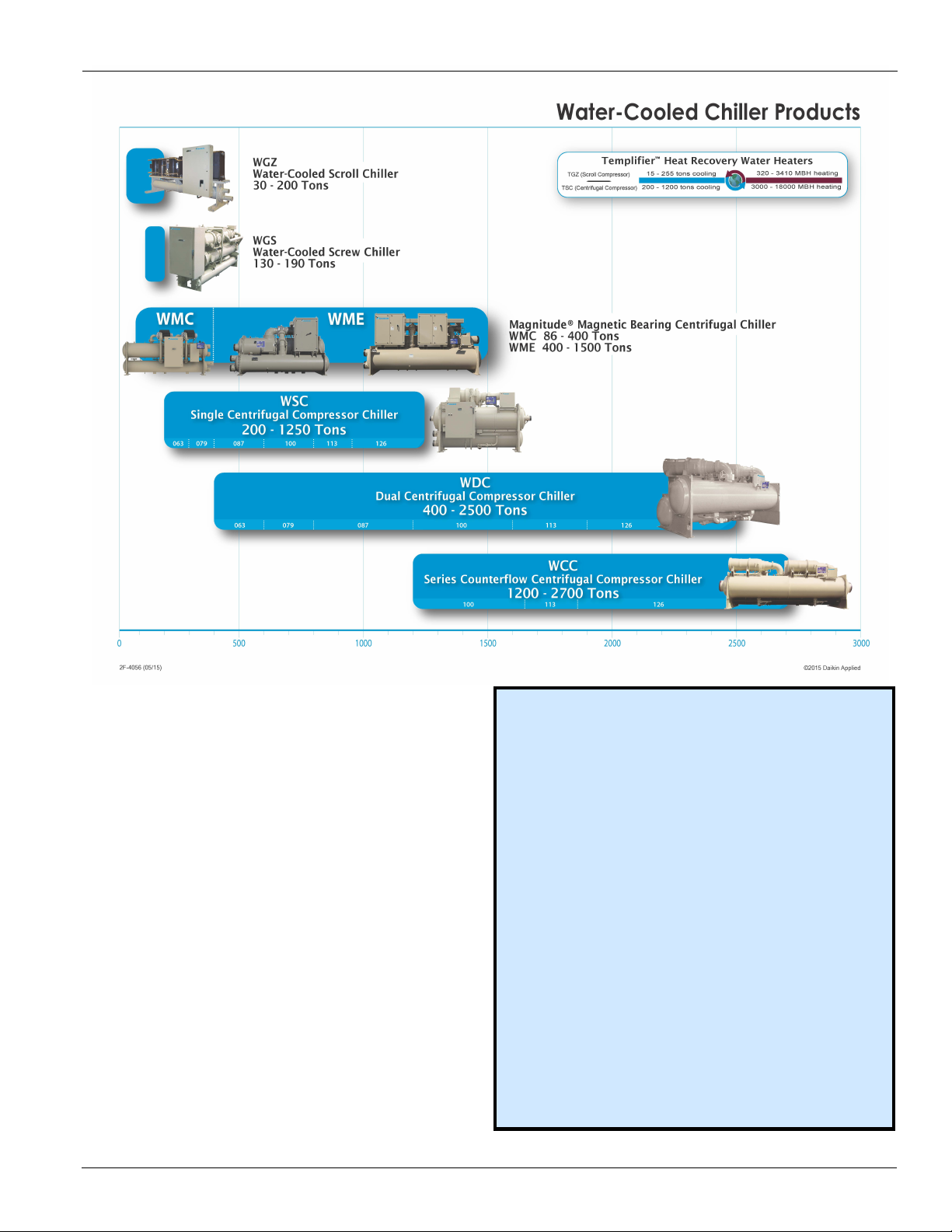
Overview of Water-Cooled Product Line
Introduction
Included in this manual:
Centrifugal Products included in separate manuals:
Model WSC
• Capacity: 200-1250 tons (AHRI conditions)
• Excellent full load performance
Model WDC
• Capacity: 400-2500 tons (AHRI conditions)
• Outstanding part load performance
• Redundancy for increased reliability
• Some sizes available with 10/11kV50Hz power option
Model WCC
• Capacity: 1200-2700 tons (AHRI conditions)
• Two refrigerant circuits for true counterflow
• Outstanding full load performance
• Some sizes available with 10/11kV50Hz power option
Magnitude™ Magnetic Bearing Compressor Chillers
Magnitude™ Model WMC
• Capacity: 145-400 tons
• Oil-free, frictionless compressor
• Excellent part-load performance
• See CAT 602 for more information
Magnitude™ Model WME
•
Capacity: 400-1500 tons
• Oil-free, frictionless compressor
• Outstanding efficiency
• See CAT 604 for more information
Templifier™ Model TSC Water Heater
• Recovers waste heat from process applications
• 5,000 - 19,000 MBH
Model HSC
• Recycles heat normally lost in cooling towers
• Hot water - 140
•
See Templifier CAT 614 for more information
o
; COP as high as 7
• Produces simultaneous heating and cooling
Cat 605-5 3
Page 4
Features and Benefits
Features and Benefits
World-Class Design Leader
As part of Daikin Industries, a Fortune 1000 company, Daikin
is the second largest air conditioning, heating, ventilating and
refrigeration company in the world. We have earned a
worldwide reputation for providing a full line of quality
products and expertise to meet the demands of our customers.
The engineered flexibility of our products allows you to fine
tune your HVAC system to meet the specific requirements of
your application. You benefit from lower installed and
operating costs, high energy efficiency, quiet operation,
superior indoor air quality (IAQ) and low cost maintenance
and service.
Daikin Centrifugal Compressor Water Chillers are
engineered for flexibility and performance - offering choices,
options and features that provide the
right solution for your
specific application-and have been doing so for over fifty
years. Some highlights of our world-class centrifugal design
are:
Design Features
Excellent Performance
Daikin offers a wide range of centrifugal vessel and
component combinations to provide the right solution for your
specific application. The single compressor WSC offers
excellent full load performance, however, in most
applications, chillers spend about 99% of their operating hours
at part-load condidtions. Our dual compressor WDC chillers
offer many attractive benefits, including outstanding part-load
efficiency, and system redundancy similar to two separate
chillers, with a lower total installed cost. WCC models also
offer the dual compressor advantage but with counterflow
vessels, and a separate refrigerant circuit for each compressor.
WCC chillers excel at full load efficiency. Contact your
Daikin representative for detailed information to decide which
model is right for your job requirements.
Table 1: Centrifugal Models & Possible Applications
Application
Cooling <1250 tons, most hours at full load WSC
Cooling >1250 tons, most hours at full load WCC
Cooling, most hours at part load WDC
Heating Application TSC Templifier™
Simultaneous Cooling and Heating HSC
Optimized Part Load Performance Optional VFD
Positive Pressure Design
Positive pressure systems offer numerous advantages over
ve pressure design. In a negative pressure system, leaks
negati
allow air, moisture, and other contaminants to seep into
system, which will gradually decrease performance, as well as
cause corrosion which must be removed. The Daikin positive
pressure design eliminates this worry, providing sustainable
performance and trouble-free ownership for the life of the unit
under normal operation.
Daikin Model
Gear Driven Advantage
Daikin’s precision-engineered gear driven design allows for
lighter components, less vibration, and ability to
select gear
ratios that will provide the optimum impeller speed for your
application. Older direct-drive designs must use large, heavy
impellers to reach similar tip speeds, which cause more
vibration and greater stress on shaft and motor during
unexpected electrical interruptions.
The compact design and lighter weight components allow for
efficient hydrodynamic bearings to be used. This means that
operation, the shaft is supported on a film of lubricant,
during
with no shaft-to-bearing contact, providing theoretical infinte
life bearings under normal circumstances. The design
simplicity of the Daikin centrifugal compressors provides
increased durability and reliable performance.
Smart Refrigerant
HFC-134a refrigerant contains no chlorine and has zero Ozone
Depletion Potential (ODP), making it an environmentally
superior alternative to other refrigerants such as HCFC-123. It
also has an A1 ASHRAE Safety Classificiation - the lowest
toxicity and flammability rating. R-134a provides the
assurance of a safe, smart, and sustainable solution.
R-123 requires about 6 times the gas flow rate (cfm/ton) of R134a, which means that the suction and discharge
piping must
also be six times larger. Using R-134a allows Daikin to
provide you with a smaller footprint chiller.
Table 2: Refrigerant Comparison
HFC-134a HCFC-123
No Ozone Depletion
Potential
No Refrigerant Phase Out
Date
ENVIRONMENTAL
Physically smaller, requiring
less mechanical room space.
In the event of a small leak,
refrigerant escapes, allowing
easy detection and repair
No purge unit required
No oil change is required
INSTALLATION AND MAINTENANCE
A1 ASHRAE Safety
Classification -
lowest
toxicity/flammability
SAFETY
RefrigerantResourceCenter for references and more information.
rating
See www.DaikinApplied.com /Daikin/DesignSolutions/
Ozone-depleting substance
Montreal Protocol requires
phase out in new equipment by
2020; production cease by 2030
Requires larger refrigerant flow
rate, with subsequent increase in
component and unit size.
In the event of a small leak, air
leaks into the chiller, making
detection and repair difficult. Can
degrade efficiency
Added cost and additional space
for a purge unit. Must
periodically purge unit to remove
contaminants
Annual oil change is
recommended
B1 ASHRAE Safety
Classification- higher toxicity
level
4 Cat 605-5
Page 5
Features and Benefits
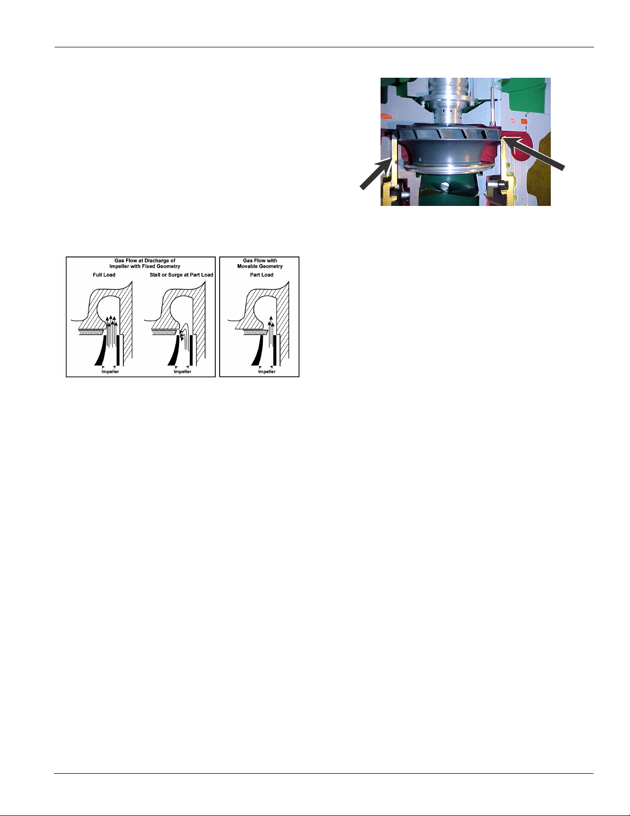
Unmatched Unloading
Daikin pioneered the use of moveable discharge geometry to
lower the surge point of centrifugal
which the compressor enters a stall or surge condition
generally limits compressor unloading. Chillers with a fixed
discharge will experience stall or surge at low loads due to
refrigerant re-entering the impeller. When in a stall condition,
the refrigerant gas is unable to enter the volute due to its low
velocity and remains stalled in the impeller. In a surge
condition the gas rapidly reverses direction in the impeller
causing excessive vibration and heat. Daikin compressors
reduce the discharge area as load decreases to maintain gas
velocity and greatly reduce the tendency to stall or surge.
Figure 1: Fixed vs. Movable Discharge Geometry
In Figure 1, above, the drawing on the left shows a crosssection view of the operation at full load of a unit with a fixed
compressor discharge. At full load, a large quantity of gas is
discharged with a fairly uniform discharge velocity as
indicated by the arrows.
The center drawing shows a fixed compressor discharge at
reduced capacity. Note that the velocity is not uniform and the
refrigerant tends to reenter the impeller. This is caused by low
velocity in the discharge area and the high pressure in the
condenser, resulting in unstable surge operation and with noise
and vibration generated.
The following cutaway picture shows the unique Daikin
movable discharge geometry. As the capacity reduces, the
movable unloader piston travels inward, reducing the
discharge cross section area and maintaining the refrigerant
velocity. This mechanism
capacity reduction.
allows our excellent unloading
compressors. The point at
Figure 2: Movable diffuser closes impeller discharge area
as load decreases.
Controls Flexibility
MicroTech II® controls with our Open ChoicesTM feature
allow easy integration with the BAS of choice using
LonTalk®, BACnet® or Modbus® protocol
Retrofit Flexibility
Easy to retrofit with flexible knock-down options. See page 55
for details.
Trouble-Free Startup
All Daikin chillers are factory tested on AHRI qualified
computer-controlled test stands. Each chiller is run-tested
under load conditions for a minimum of one hour with
evaporator and condenser water flow at job conditions
(excluding glycol applications). Operating controls are
checked and adjusted, and the refrigerant charge is adjusted for
optimum operation and recorded on the unit nameplate. Units
operating with 50-Hz power are tested with a 50-Hz power
supply. The testing helps ensure correct operation prior to
shipment, and allows factory calibration of chiller operating
controls.
All domestic Daikin centrifugal chillers are commissioned by
Daikin Factory Service personnel, or by authorized and
experienced
ensure that proper starting and checkout procedures are
employed and helps in a speedy commissioning process,
giving you confidence that your chiller is operating as
expected.
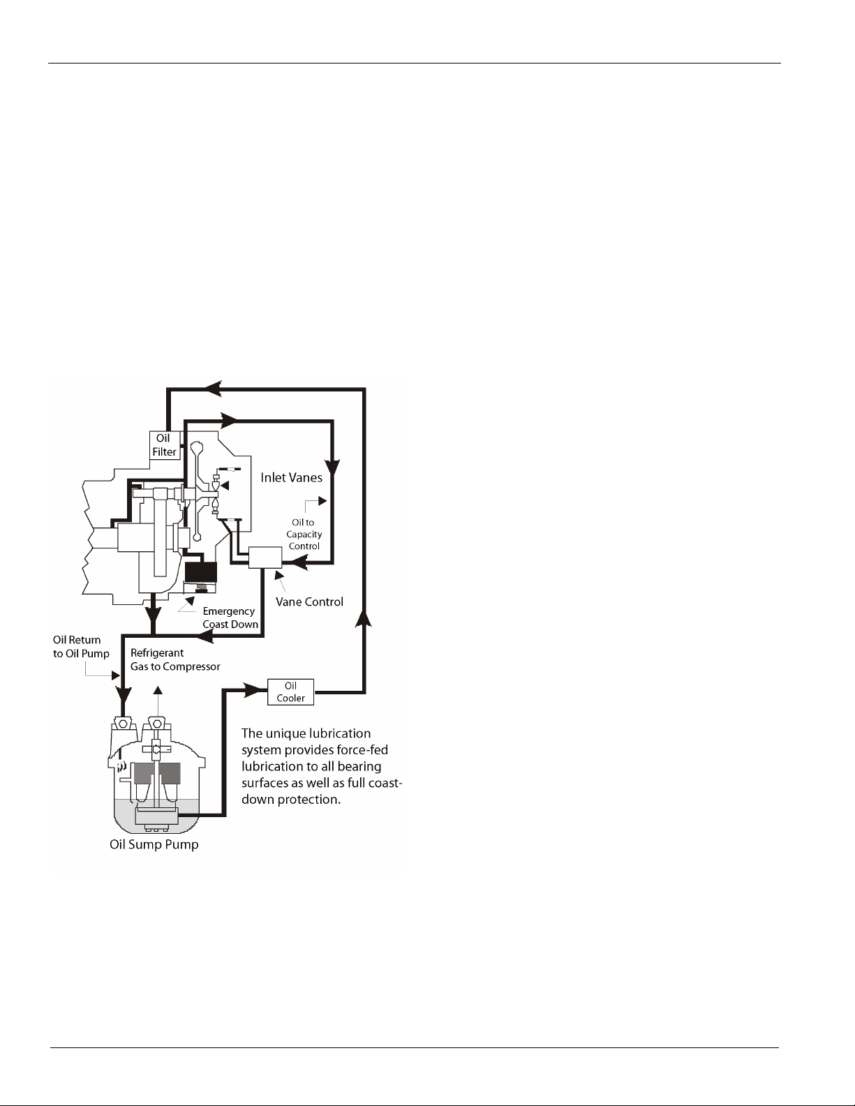
Lubrication System
A separately driven electric oil pump assembly supplies
lubrication at controlled temperature and pressure to all
bearing surfaces and is the source of hydraulic pressure for the
capacity control system.
Daikin startup technicians. This procedure helps
The control system will not allow the compressor to start until
oil pressure, at the proper temperature, is established. It also
allows the oil pump to operate after compressor shutdown to
provide lubrication during coast-down. Lubricant from the
pump is supplied to the compressor through a water-cooled,
brazed-plate heat exchanger and single or dual five-micron oil
filters internal to the compressor. All bearing surfaces are
Cat 605-5 5
Page 6
Dual Compressor Centrifugal Chillers
pressure lubricated. Drive gears operate in a controlled
lubricant mist atmosphere that efficiently cools and lubricates
them.
Lubricant is made available under pressure from the
compressor oil filter to the unit capacity control system and is
used to position the inlet guide vanes in response to changes in
leaving chiller water temperature.
If a power failure occurs, an emergency oil reservoir provides
adequate lubrication flow under pressure, and prevents damage
that could occur during the coast-down period with the oil
pump stopped.
Since the Daikin chillers are positive pressure, there is no
need to change the lubricant or filter on a regular basis. As
with any equipment of
this type, an annual oil check is
recommended to evaluate the lubricant condition.
Figure 3: Lubrication System Schematic
is gas rapidly reversing direction through the impeller). A
number of things can contribute to this condition including
inadequate maintenance of condenser tube cleanliness, a
cooling tower or control malfunction, or unusual ambient
temperatures among others.
For these abnormal conditions, Daikin compressor
designers have developed a protective control system that
senses the potential for a surge, looks at the entire chiller
system operation and takes corrective action if possible;
or
stops the compressor, to help prevent any damage from
occurring. This protection is provided as standard on all
Daikin centrifugal compressors.
Dual Compressor Centrifugal Chillers
Dual Compressor Experience
Daikin is the expert when it comes to dual centrifugal
compressor technology. We
have been successfully building
dual compressor centrifugal chillers since 1971. Daikin is the
only company that builds them with either a single refrigerant
circuit (Model WDC) or two refrigerant circuits (Model
WCC).
Benefits of Dual Compressor Chillers
Superior Efficiency
When coupled with a variable frequency drive, the extremely
efficient Dual Compressor Chillers are considerably more
efficient than single compressor chillers in the same size range,
with IPLVs (Integrated Part Load Value) as low as 0.3 kW per
ton. IPLV conditions are set by AHRI and subject to stringent
testing. Insist on AHRI-certified IPLV efficiency when making
efficiency comparisons.
Enhanced Surge Protection
When centrifugal compressors operate at part load, the volume
of refrigerant gas entering the impeller is reduced. At the
reduced flow, the impeller's capacity to develop the peak load
head is also reduced. At conditions of low refrigerant flow and
high compressor head (pressure difference), stall and/or surge
can occur (a stall is gas static in the impeller, a surge condition
The Redundancy Feature
Daikin dual centrifugal chillers have two of everything
connected to the evaporator and condenser - two
compressors, two lubrication systems, two control systems,
and two starters.
If any component on a compressor system fails, the component
can be removed or repaired without shutting down the other
compressor; providing an automatic back-up with at least 60
percent of the chiller design capacity available on WDC units
and 50 percent on WCC units.
Redundancy is also built into the distributed control system,
which consists of a unit controller, a compressor controller for
each compressor and an operator interface touch screen. The
chiller will operate normally without the touch screen being
functional. If a compressor controller is unavailable, the other
compressor will operate normally and handle as much of the
load as possible.
Lower Installed Costs
The redundancy feature pays off in lower installed costs. An
example of how to incorporate dual compressor chillers into a
system requiring redundancy:
6 Cat 605-5
Page 7
Dual Compressor Centrifugal Chillers
WSC Single Compressor Chillers WDC Dual Compressor Chillers
(2)
600 ton (2100 kW) On Line Units
(2)
750 ton (2100 kW) Units with
+(1)
600 (2100 kW ) t on Standby Unit 1,200 (4200 kW ) On Line tons
*
1,800 ton (6300 kW) Installed Capacity 1500 ton (52 50 kW ) Ins ta lled Capacit y
Job requirement: 1,200 tons (4200 kW), 50% Backup
*One 750-ton (2100 kW) dual chiller running on two compressors for 750 tons (2100
kW), plus one 750-ton (2100 kW) dual chiller running on one compressor for 60% of 750
tons (2100 kW) = 450 tons (1575 kW), for a total of 1200 tons (4200 kW) on any 3 of the
4 total compressors.
The elimination of the extra pumps, valves, piping, controls,
rigging, and floor space can result in as much as a 35%
reduction in the installation cost for a chiller plant, plus the
savings on the chillers themselves.
Dual Compressor Chiller Overview
There are subtle but important differences between the single
circuit WDC and two circuit WCC chillers.
Dual Circuit WCC Counterflow Chillers
These chillers have a separate refrigerant circuit for each
compressor. They are available in single pass only. They
provide the high full load efficiency advantage of two separate
chillers arranged for counterflow operation in a single,
compact unit.
Single Circuit WDC Chillers
These chillers have a single-refrigerant circuit for the
evaporator and condenser with two compressors running in
parallel and are available in one, two or three-pass
configurations. Their salient feature is that at singlecompressor, part load operation, the running compressor can
utilize the entire chiller's heat transfer surface, providing
outstanding part load performance.
Application of Dual Compressor Chillers
Designers and owners must decide which chiller type, or
combination of chiller types, is best for their installation.
Considerations include first cost, system efficiency, system
reliability, space requirements, and total owning costs.
Use WCC chillers when:
• Project requirement is lowest kW per ton performance at full
load with high electrical demand charges.
• Project has a large central plant where cycling chillers for
system capacity reduction is expected (three or more
chillers).
• High chilled water delta-T and low water pressure drops are
desired.
• Built-in redundancy is required. A single compressor will
provide 50% of the unit's full load capacity.
• High efficiency and large capacity is required with series
flow. Use two WCC units in series-counterflow in the 3,000
to 4,000 ton range.
Use WDC chillers when:
• Project requirement is overall lowest energy consumption
with best part load performance.
• Project has smaller chilled water plant where unit unloading
is expected versus cycling of chillers associated with large
multi-chiller plants.
• Floor space is limited (16-foot vessel length compared to 20foot for WCC).
• Two or three pass vessels are required, typical of retrofit
applications.
• Built-in redundancy is required. A single compressor will
provide 60% of the unit's full load capacity.
Use a combination of WDC and WCC chillers when:
• Peak overall system efficiency is important; for example,
use three WCC and one WDC chiller, all in parallel. The
WCC units are optimized for running at full load and the
WDC is optimized for part load operation. The WCC units
cycle on and off and the WDC unit (consider variable
frequency drives on this unit) trims the load, running
between five and one hundred percent capacity.
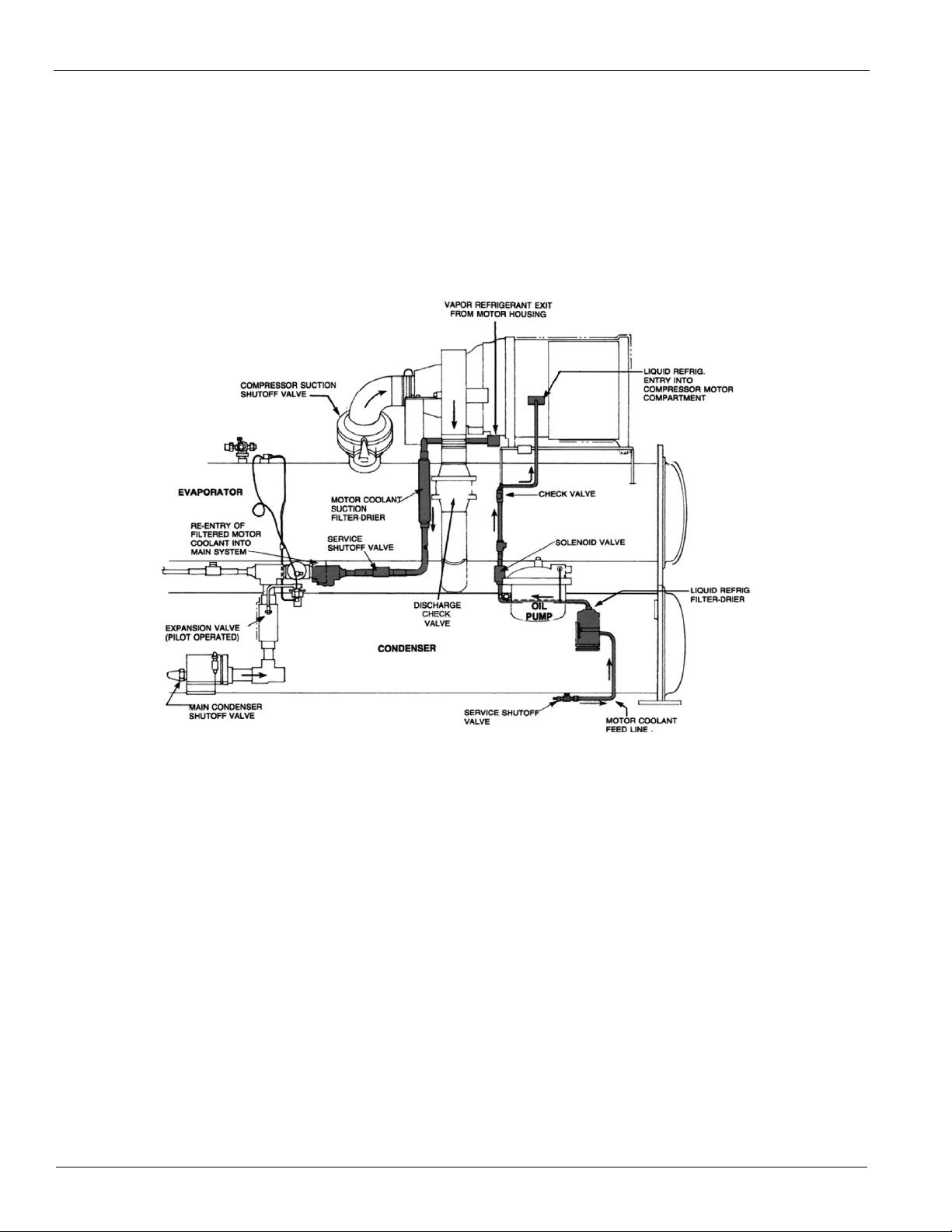
Why a Compressor Motor Failure Will Not Contaminate the
Common Refrigerant Circuit on WDC dual chillers
Some people are concerned with the result of a motor burnout
on a single-circuit dual compressor chiller. This is not a
problem on the Daikin WDC chillers because of compressor
construction and chiller layout.
The compressor motor is isolated from the main refrigerant
flow circuit so that any contaminants generated by a motor
failure will not pass into the main refrigerant circuit. Moisture,
acid and/or carbon particles will be automatically trapped
within the compressor's dedicated coolant feed and exit lines.
Internally, the compressor motor compartment is separated and
sealed from the main refrigerant compression chamber. A
double shaft seal on the motor side of the gear housing
prevents cross flow of refrigerant along the motor shaft. The
motor coolant feed line is equipped with both a solenoid valve
and a check valve. These mechanical components, plus the
higher pressure of the liquid refrigerant, prevent back feed into
the main refrigerant system. Refrigerant vapor exiting the
motor compartment must pass through a high pressure drop
filter-drier, sized to immediately plug up and seal off the motor
compartment. Both the coolant feed and return lines are
equipped with manual shutoff valves to permit component
service.
Cat 605-5 7
Page 8
Dual Compressor Centrifugal Chillers
Over 30 years of field experience have proven the reliability of
these compressor motors. Despite the reliability inherent in the
motor design and the protective control, electrical distribution
system faults and lightning strikes can occur that are beyond
the control of the most conscientious designer. The coolant
protective system protects the unit charge from being
contaminated.
Special WDC Warranty: In the unlikely event of a motor
burnout, the chiller refrigerant charge will not be
Figure 4: Motor Cooling
contaminated. This is so well proven that it is guaranteed for
five years. In areas supported by Daikin Factory Service, if a
motor burnout occurs in one compressor and contaminates the
refrigerant circuit, any resultant damage to the other
compressor will be repaired and the refrigerant charge replaced
at no cost to the customer for parts and labor. The terms of the
original chiller warranty apply to the original burned out
compressor.
Efficiency
Chillers usually spend 99% of their operating hours under part
load conditions, and most of this time at less than 60% of
design capacity. One compressor of a dual WDC chiller
operates with the full heat transfer surface of the entire unit.
For example, one 500-ton (1,750 kW) compressor on a 1,000
ton (3,500 kW) dual chiller utilizes 1,000 tons (3500 kW) of
evaporator and condenser surface. This increases the
compressor's capacity and also results in very high efficiency.
Typical efficiencies for a WDC dual chiller, taken from a
selection computer run, look like this:
Full load efficiency: 0.550 kW per ton (6.5 COP)
60% load, one compressor: 0.364 kW per ton (9.6 COP)
IPLV: 0.415 kW per ton (8.5 COP)
The addition of VFDs to the WDC dual
produces an astonishing AHRI certified IPLV of 0.340 for the
above case. Specific selections can vary up or down from this
example. IPLV is defined in the Selection section of this
manual beginning on page 28 .
8 Cat 605-5
compressor chiller
WCC chillers, with their counterflow design, excel at full load
efficiency. Each of the two compressors operates at a lower
head (pressure differential) than single compressor chillers in
parallel. With any pump or compressor, lower head means
lower power for a given flow. As shown on the right, the #2
(downstream compressor) makes 42 F water but has only 89 F
condenser water leaving instead of 95 F typical of a single
compressor unit. The #1 compressor has 95 F condenser water
leaving, but only has to make 47.6 F chilled water.
The Replacement Market Advantage
• Bolt-together construction on single and dual compressor
chillers along with factory disassembly available as an
option simply the tough entrance situations.
• Put 20% or more tons in the same footprint.
• Add dual compressor redundancy.
• Greatly reduce chiller energy consumption.
• Install a refrigerant with no phase-out date.
• Opens many options for multiple chiller plants using WSC,
WDC and WCC combinations.
Page 9
Heat Recovery Models
EVAPORATOR
TOW E R
COND ENSER
RE COV E RY
COND E N SE R
AUXILI ARY
HE ATER
HEAT L OAD
TCTCCOO LI N G
LOAD
OPEN
CI RC UI T
TOWER
HEAT REC OVERY
CHI LLER
LEGEND
TC TEMPERATURE CONTROL POINT
PUMP
Typical Building Types
Hotels/Motels
Health Care
Athletic Facilities
Resorts
Schools
Food Service
Nursing Homes
Typical Applications
Space Heating
Outside Air Heating
Reheat
Service Hot Water
Laundries
Kitchens
G
TOWER
)
G
HEATER
R
R
CONDENSER
R
COOLING
R
90° F
(35°C)
F
CHILLER
TC
TC
C
Heat Recovery Models
Heat Recovery Models
For decades, Daikin has pioneered the use of heat recovery
chillers and the unique Daikin
Water Heater to reduce energy costs. These products have
become more important than ever with the current emphasis
on total building efficiency. ASHRAE Efficiency Standard
90.1 mandates the use of heat recovery equipment of this
type in a wide range of buildings.
Heat Recovery Chillers
Model HSC heat recovery chillers, with a single compressor,
have a single condenser with split bundles, i.e., two separate
water passages divided by separate water heads as shown in
the photograph to the right. The inboard water connections are
connected to the cooling tower, the other water side is
connected to the heating system.
The economic feasibility of hot water generated with these
units depends on heating and cooling load profiles and on the
relative cost of the available energy sources. A compressor's
kW per ton is heavily influenced by the pressure head it is
pumping against. During heat recovery operation, the entire
cooling load is operating against the high head required by the
Templifier Heat Pump
hot water temperature. For this reason, it is desirable to
maximize the percentage of the
total rejected heat used for the
heating load. Daikin's economic evaluation program, Energy
Analyzer , available on CD from your local Daikin sales
office, is the perfect tool to determine the economic feasibility
of using this proven technology.
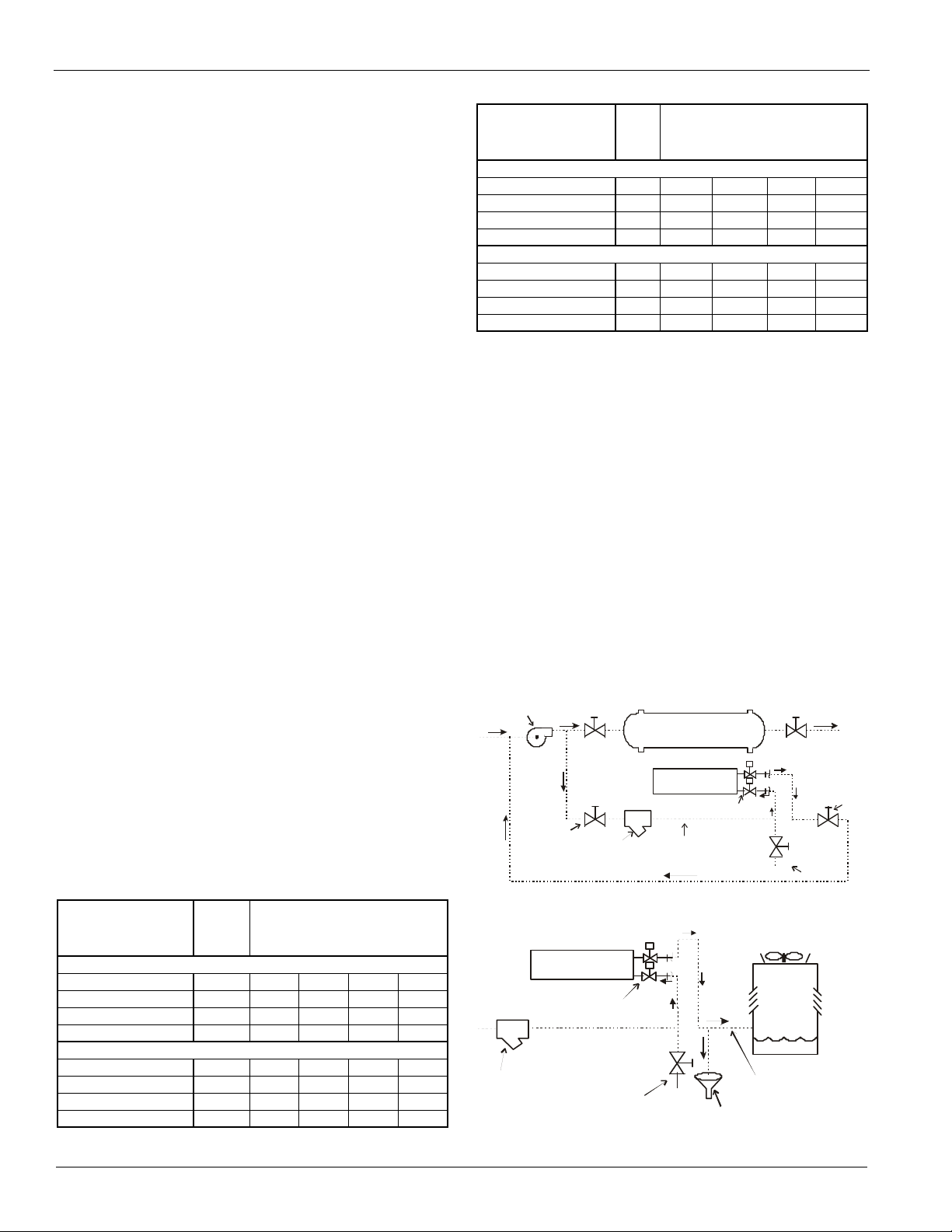
Figure 5: Heat Recovery Chiller Piping Schematic
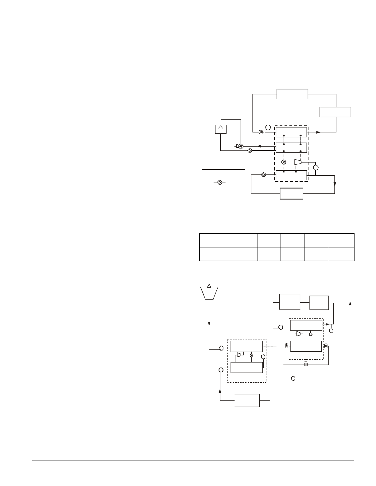
Templifier Heat Pump Water Heaters
Model TSC: 5,000 to 19,000 MBH
The Model TSC Templifier was developed in the 1970s, after
the 1973 oil embargo, as a device to replace fossil-fired water
heaters with electric heaters. The concept was simple; direct a
stream of warm waste heat to the evaporator of a refrigeration
unit, amplify the temperature of the heat through the
compression cycle, and then deliver the heat from the
condenser, at a higher useful temperature, to a heating load.
The flow diagram shown to the left illustrates just how the
Templifier unit is placed
decision to include a Templifier water heater is almost always
a financial one. Evaluation of load profiles, energy costs, and
owning costs is made simple by using the Daikin Energy
Analyzer evaluation program to determine if the return on
investment meets the owner's requirements.
When there is sufficient waste heat available, Templifier units
can be very attractive where fossil fuels are not available, or
where their use is restricted due to pollution problems or other
reasons. Compared to electric resistance heating, the energy
cost for a Templifier unit to heat domestic water, for example,
could be 7 to 8 times less!
Where to Use Templifier Water Heaters:
in a chilled water system. The
Table 3: Typical COP’s
Hot Water
Temperatures
COP (Based on 85F
off Chiller to Templifier)
110F 120F130F 140F
8.3 6.8 6.0 4.5
Figure 6: Templifier Heat Pump Water Heater Schematic
COOLI N
85°
(29°C)
55°F
(13°C)
EVAPO RATO
12 5°F
(52°C
45°F
(7 ° C )
95 °F
HEATIN
LOAD
TEMPLI FI ER HEAT
PUMP WAT ER HEATE
T
SUPPLE-
MENTAL
CONDE NSE
EVAPORAT O
TEMPE RATURE CONTRO L
13 5°F
(57°C)
(32° )
Cat 605-5 9
LOA D
Page 10
Heat Recovery Models
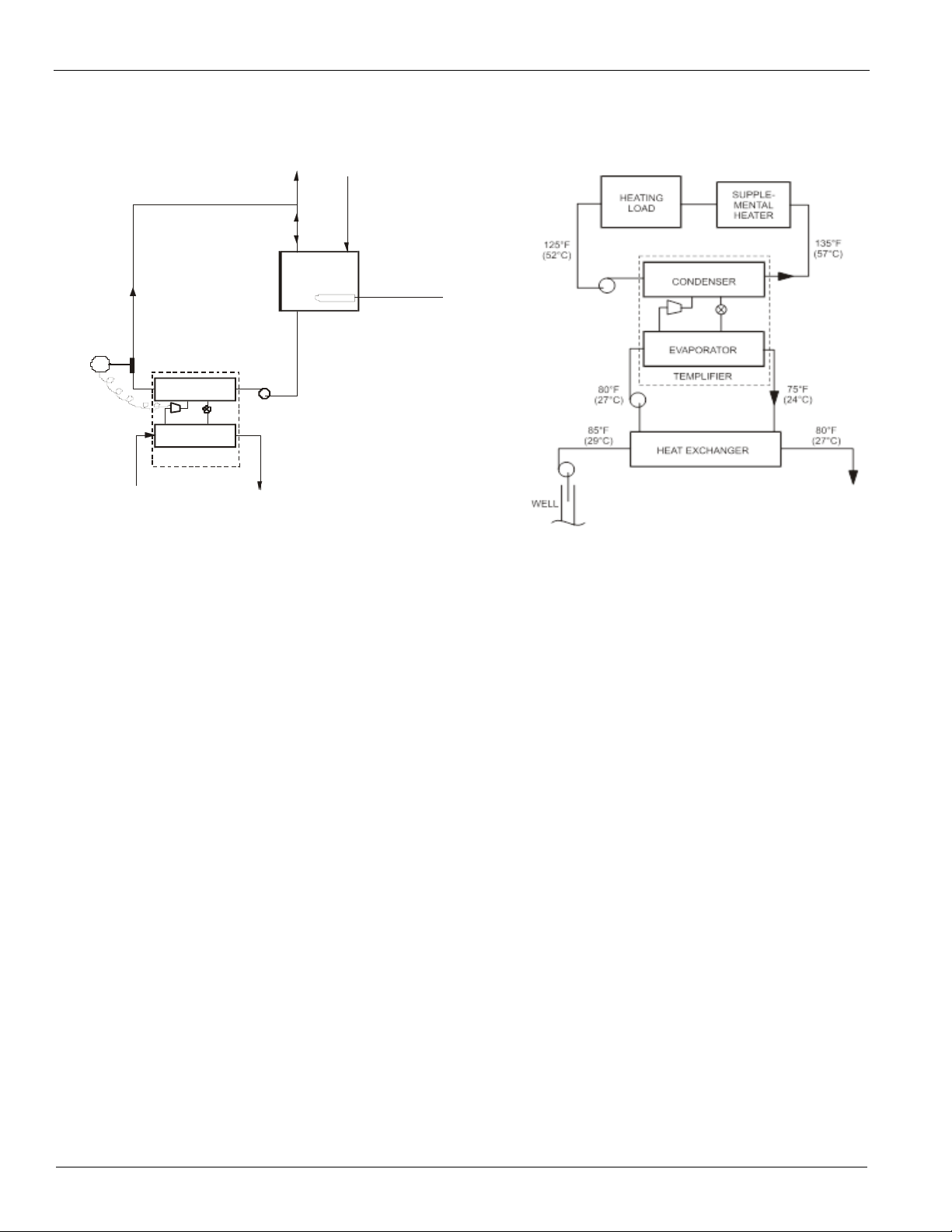
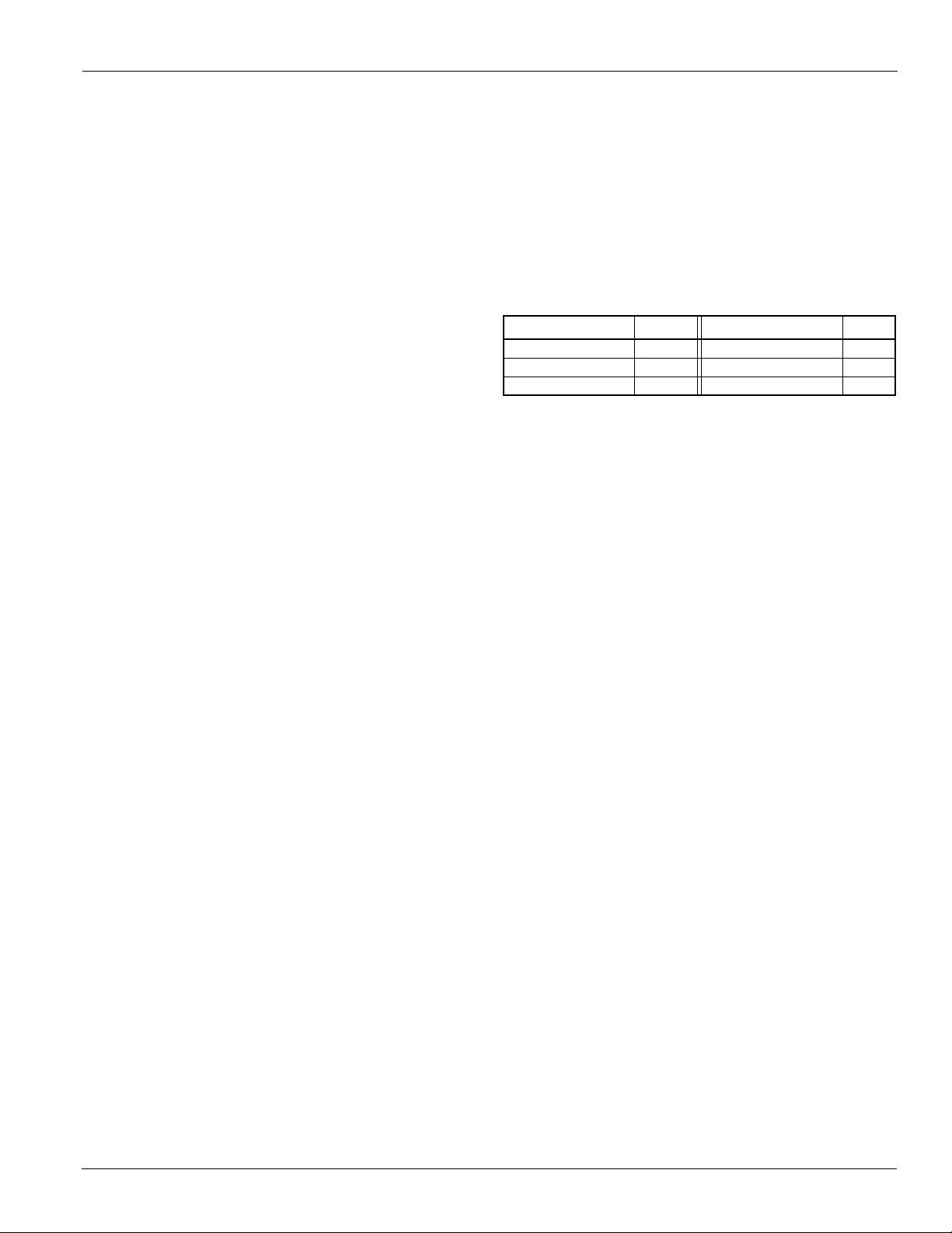
Intermediate Heat Exchanger
Ground Water Heat Source
Service Hot Water Piping
CONDENSER
EVAPORATOR
ST OR AG E
TA N K
140°F
(60°C)
TEMPLIFIER
HEAT
SOURCE
140°F
(60°C)
140°F
(60°C)
RETURN /
MAKEUP
OUTP UT
STANDBY /
A UXI LI AR Y HE AT
T- C
Figure 7: Typical Templifier Applications
Heat Recovery Models
10 Cat 605-5
Page 11
Controls
Controls
MicroTech® II Controls
Daikin Centrifugal chillers are equipped with the proven
reliability of the MicroTech® II controls system with touchscreen interface. The control system is designed for easy and
intuitive operation, and configured for efficient and reliable
operation. Plus, Daikin's Open Choices™ feature allows
integration with your building automation system (BAS)
through an optional communication module
(see Options and Accessories section, page 52).
Designed with the System Operator in Mind
Reliable, economic use of any chiller depends on an easy
operator interface. That's why operation simplicity was one of
the primary considerations
MicroTech® II controller and Operator Interface Touch-Screen
(OITS). The 15-inch color touch-screen is mounted on a fully
adjustable arm. The chiller is graphically displayed, with key
operating parameters viewable on the screen. Alarm history
and operation setpoints are easily accessed through intuitive
touch-screen buttons. The chiller operating manual is also
viewable on the touch screen and can be downloaded via USB.
MicroTech® II Controls Enhance Operating Economy
Many features have been integrated into MicroTech II controls
to ensure optimum operating economy. In addition to replacing
normal relay logic circuits, we've enhanced the controller's
energy saving capabilities with the following features:
• Direct control of water pumps Optically isolated, digital
output relays provide automatic lead-lag of the evaporator
and condenser pumps, permitting pump operation only when
required.
• User-programmable compressor soft loading Prevents
excessive power draw during pull down from high chilled
water temperature conditions.
in the development of the
• Chilled-water reset Reset the leaving water temperature
based on the return water temperature. Raising the chilled
water setpoint during periods of light loads dramatically
reduces power consumption.
• Demand limit control Maximum motor current draw can be
set on the panel, or can be adjusted from a remote 4-20ma or
1-5 VDC BAS signal. This feature controls maximum
demand charges during high usage periods.
• Condenser water temperature control Capable of four
stages of tower fan control, plus an optional analog control
of either a three-way tower-bypass valve or variable speed
tower-fan motor. Stages are controlled from condenser-water
temperature. The three-way valve can be controlled to a
different water temperature or track the current tower stage.
This allows optimum chilled water plant performance based
on specific job requirements.
• Staging Options (Multiple Chiller Installations) The
MicroTech® II controller is capable of compressor
staging decisions and balancing compressor loads
between up to four WSC,WDC or WSC Daikin chillers
using defaults or operator-defined staging.
• Plotting Historic Trends Past operation of the chiller can be
plotted as trend lines and even downloaded to a spreadsheet
for evaluation and analysis.
Proactive Controls
MicroTech® II controls constantly monitor chiller status, and
automatically take
proactive measures to relieve abnormal
conditions or shut the unit down if a fault occurs. For example,
if a problem occurs in the cooling tower and discharge
pressure starts to rise, the controller will automatically hold the
load point and activate an alarm signal. A further rise in
pressure will initiate compressor unloading in an effort to
maintain the setpoint pressure. If the pressure continues to rise,
the unit will shut off at the cutout pressure setting to protect
the unit.
Table 4: Daikin MicroTech® II Controls Features and Benefits
FEATURE BENEFIT
Open Choices™ Option
Touch-screen Interface
Alarm/Fault History and Trend Logging Historical trend data can be downloaded from an onboard USB port
Precise 0.2 F chilled water controls Provides stability in chilled water system
Proactive Controls
Integrated lead/lag pump control
Condenser Water Temperature Control Provides tower fan control /modulation based on system conditions
Multiple language capability -
Metric or IP units of measure
Cat 605-5 11
Easy integration into a building management system via a factory or field-installed
module communicating with BACnet , LONMARK or Modbus protocols.
Easy to read, adjustable, large 15-inch, color touch screen;
See chiller operation at a glance; easily view and change setpoints
Proactive correction of “unusual conditions” allows chiller to stay online; activates
alarm and modifies chiller operation to provide maximum possible cooling
Automatic control of chilled water and condenser water pumps; permits pump
operation only when required
Great asset for world-wide applications
Page 12
Controls
Alarm History for Easy Troubleshooting
The controller memory can retain and display the cause of the
current fault and the last twenty-five fault conditions. This
feature is extremely useful for troubleshooting and
maintaining an accurate record of unit performance and
history.
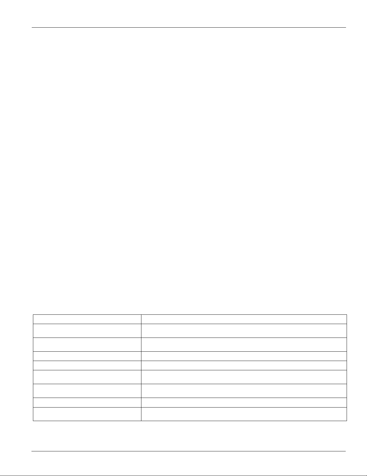
The Home Screen shown below is the primary viewing screen
on the Operator Interface Touch Screen (OITS). It gives realtime data on unit status, water temperatures, chilled water
setpoint and motor amp draw.
Figure 8: OITS Home Screen
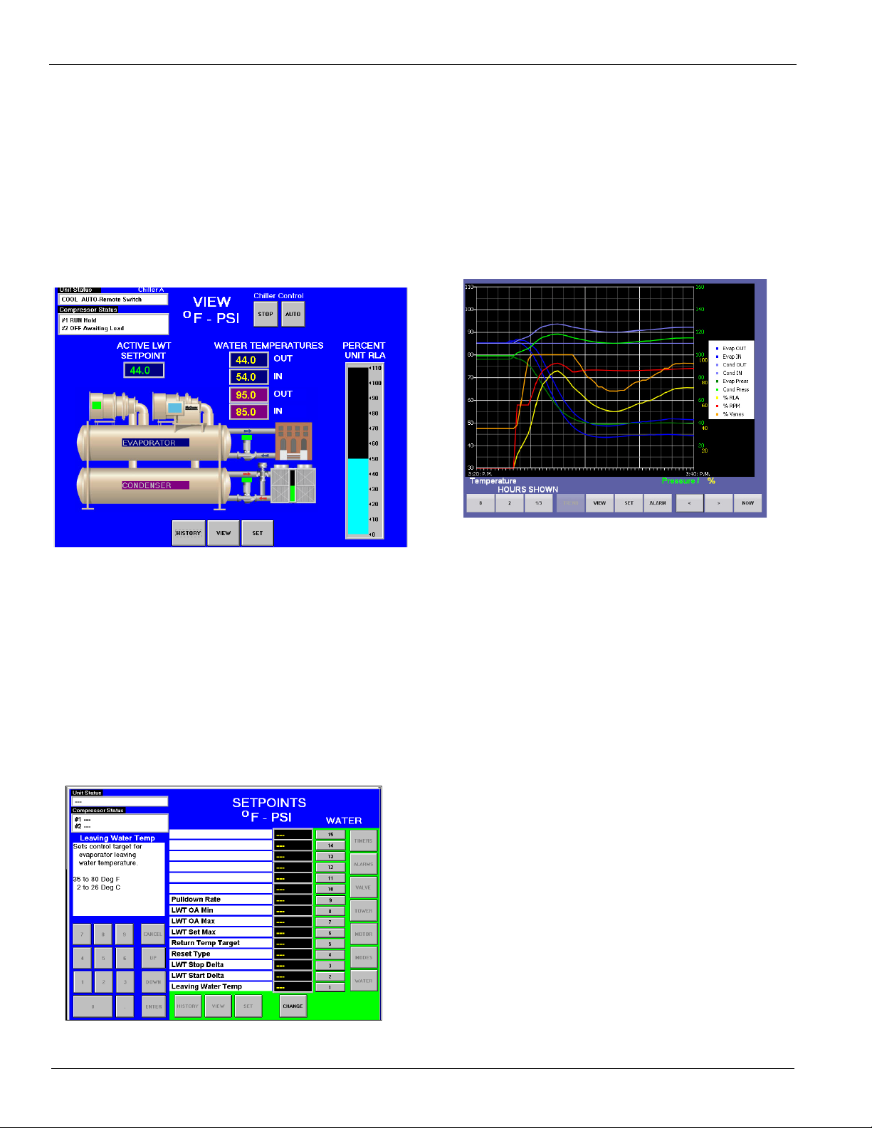
Trend Logging
Ever wonder how your chiller performed last night? Were you
holding the correct chilled water temperature? What kind of
cooling load did the chiller have? The Daikin MicroTech® II
controller can provide the answers, thanks to its huge
memory, and plot water temperatures, refrigerant pressures,
and motor load data. These values can also be downloaded
through a convenient USB port (located on the unit control
panel) into a spreadsheet for detailed evaluation and analysis.
Figure 10: OITS Trend History Screen
If an alarm occurs, a red button appears on the screen that
leads to the Active Fault Screen whichgives complete fault
information so that the fault can be corrected and cleared.
Changing Setpoints
Changing setpoints is easy with the MicroTech II control. For
example, to change the chilled water setpoint, press SET
button from any screen, then press WATER and this screen
appears, now press button #1, Leaving Water Temperature, and
you are ready to input a password and a new value. (The
controller features a three-level password security system to
provide protection against unauthorized use.)
Figure 9: OITS Setpoint Screen
WDC/WCC Chiller Controls
Dual compressor model centrifugal chillers feature a
MicroTech® II unit controller and a separate controller for
each compressor. This distributed control scheme allows the
operation of each compressor in
Performance data for each compressor is monitored separately
by each controller, and can be controlled and monitored on the
interface panel.
Compressor staging and the load balance function are standard
features
the compressor with the fewest number of starts first, and will
only start remaining compressors when sufficient load has
been established. The staging function will stop the
compressor with the most run-hours as the load decreases to
single compressor range. During two-compressor operation,
the load balance function will equalize the load between each
compressor, providing optimum unit efficiency.
Versatile Communications For Even More Control
For flexibility there are three ways to interface with the
MicroTech® II controller:
• Direct entry via Operator Interface Touch-Screen.
• Direct entry as above, plus remote digital and analog input/
of MicroTech® II controllers. Smart scheduling starts
output signals for certain functions such as enable run input,
alarm signal output, chilled water reset and load limiting,
outputs for pump and tower fan control, for variable speed
tower fan and/or tower bypass valve.
dependently from the other.
12 Cat 605-5
Page 13
Controls
• Interface with a building automation system (BAS) with
optional modules, communicating directly with BACnet,
have received LONMARK certification with the optional
LONWORKS communication module.
LONMARK or Modbus protocols.
Protocol Options
Building Automation Systems
All MicroTech II®
controllers are capable of communication
with BAS, providing seamless integration and comprehensive
monitoring, control, and two-way data exchange with industry
standard protocols such as LONMARK , Modbus or BACnet .
•BACnet MS/TP
•BACnet IP
• BACnet Ethernet
• LONWORKS (FTT-10A)
• Modbus RTU
Open Choices Benefits
• Easy to integrate into your building automation system
• Factory- or field-installed communication modules
The BAS communication module can be ordered factorymounted with your chiller, or can be field-installed at any time
after the chiller is installed.
• Comprehensive point list for system integration, equipment monitoring and alarm notification
• Comprehensive data exchange
Electric Power Options
In order for the BAS to read the full complement of power data
on low and medium voltage solid state, across-the-line, and
Integration Made Easy
Daikin unit controllers strictly conform to the interoperability
guidelines of the LONMARK Interoperability Association
and the BACnet Manufacturers Association. They
Table 5: Typical BAS Read/Write Data Points
Typical Data Points
Active Setpoint R Cond EWT R Evap Water Pump Status R
Actual Capacity R Cond Flow Switch Status R Heat Recovery EWT R
Capacity Limit Output R Cond LWT R Heat Recovery LWT R
Capacity Limit Setpoint W Cond Pump Run Hours R Heat Setpoint W
Chiller Enable W Cond Refrigerant Pressure
Chiller Limited R Cond Sat. Refrigerant Temp
Chiller Local/Remote R Cond Water Pump Status R Liquid Line Refrigerant Temp R
Chiller Mode Output R Cool Setpoint W Maximum Send Time W
Chiller Mode Setpoint W Current Alarm R Minimum Send Time W
Chiller On/Off R Default Values W Network Clear Alarm W
Chiller Status R Evap EWT R Oil Feed Pressure R
Compressor Discharge Temp R Evap Flow Switch Status R Oil Feed Temp R
Compressor Percent RLA R Evap LWT for Unit R Oil Sump Pressure R
Compressor Run Hours R Evap LWT for Compressor R Oil Sump Temp R
Compressor Select W Evap Pump Run Hours R Outdoor Air Temp
Compressor Starts R Evap Refrigerant Pressure R2 Pump Select W
Compressor Suction Line Temp R Evap Sat. Refrigerant Temp R2 Run Enabled R
1.) Data points available are dependent upon options selected
2.) Per compressor
wye-delta starters, the optional Field Metering Package must
be ordered with the chiller. Otherwise the BAS will only read
the average unit amps. This power data is not available to a
BAS on all other starter voltages and types.
1
(W = Write, R = Read)
2
Ice Setpoint W
R
2
Liquid Line Refrigerant Pressure
R
Cat 605-5 13
Page 14
Application Considerations
Application Considerations
Location
These chillers are intended only for installation in an indoor or
weather protected area consistent with the NEMA 1 rating on
the chiller, controls, and electrical panels. If indoor subfreezing temperatures are possible, special precautions must be
taken to avoid equipment damage. Equipment room
temperature for operating and standby conditions is 40°F-
122°F (4.4°C-50°C)
CAUTION
Daikin Centrifugal Chillers are intended only for installation in indoor
areas protected from temperature extremes. Failure to comply may
result in equipment damage and may void the manufacturer warranty.
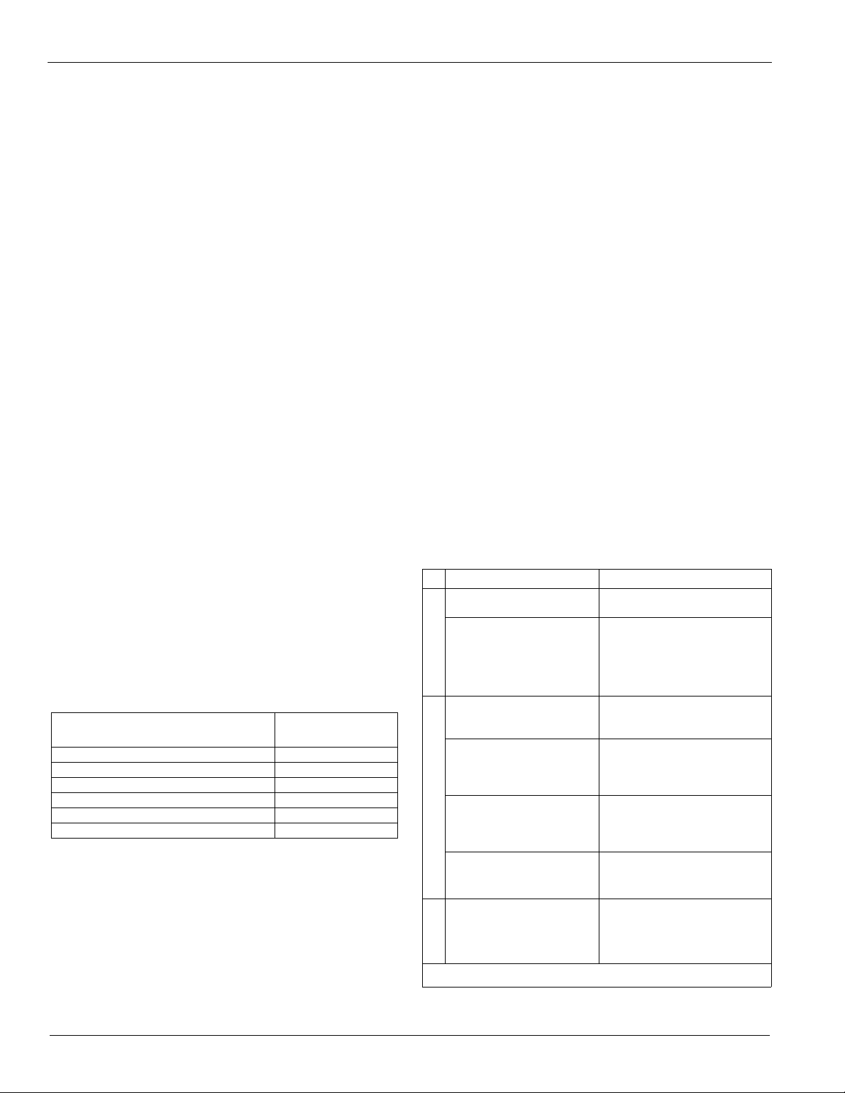
Operating/Standby Limits
Table 6: Operating/Standby Limits
Equipment room operating temperature: 40°-104°F (4.4°-40°C)
Equipment room temperature, standby,
with water in vessels and oil cooler:
Equipment room temperature, standby,
without water in vessels and oil cooler:
Maximum entering condenser water
temperature, startup:
Maximum entering condenser water
temperature, operating:
Minimum entering condenser water
temperature, operating:
Minimum leaving chilled water
temperature:
Minimum leaving chilled fluid temperature
with correct anti-freeze fluid:
Maximum entering chilled water
temperature, operating:
Maximum oil cooler entering
temperature:
Minimum oil cooler entering
temperature:
Piping
Piping must be adequately supported to remove weight and
strain on the chiller's fittings and connections. Do not use
PVCor CPVC piping. Be sure piping is adequately insulated.
Install a cleanable 20-mesh water strainer upstream of the
evaporator and condenser. Install enough shutoff valves to
permit draining water from the evaporator or condenser
without draining the complete system.
CAUTION
Freeze Notice: The evaporator and condenser are not selfdraining. Both must be blown out to completely remove water
to help prevent freeze-up
.
Include thermometers and pressure gauges at the chiller inlet
and outlet connections and air vents at the high points of
piping. The water heads can be interchanged (end for end),
allowing water connections to be made at either end of the
40°-104°F (4.4°-40°C)
0°F-122F (-18°C-50°C)
design + 5°F (2.7°C)
job-specific design
temperature
see this page.
38°F (3.3°C)
15°F (9.4°C)
90°F (32.2°C)
80°F (26.7°C)
42°F (5.6°C)
unit. Use new head gaskets when interchanging water heads.
When water pump noise is objectionable, use rubber isolation
sections at both the inlet and outlet of the pump. Vibration
eliminator sections in the condenser inlet and outlet water lines
are not normally required. Where noise and vibration are
critical and the unit is mounted on spring isolators, flexible
piping and conduit connections are necessary. If not factory
installed, a flow switch or pressure differential switch must be
installed in the leaving chilled water line in accordance with
the flow switch manufacturer's instructions.
Note: Victaulic connections are AWWA C-606. Field supply
transitions if Victaulic brand AGS® (Advanced Groove
System) type grooves are used on the field piping.
Optimum Water Temperatures and Flow Rates
A key to improving energy efficiency for any chiller is
minimizing the lift, or pressure difference, between the
compressor suction and discharge pressures. Reducing the lift
reduces the compressor work, and hence its energy
consumption per unit of output. The chiller typically has the
largest motor of any component in a chilled water system.
Higher leaving chilled water temperatures
Warmer leaving chilled water temperatures will raise the
compressor's suction pressure and decrease the lift, improving
efficiency. Using 45 F (7.0 C) leaving water instead of 42 F
(5.5 C) will make a significant improvement.
Evaporator temperature drop
The industry standard has been a ten-degree temperature drop
in the evaporator. Increasing the drop to 12 or 14 degrees will
improve the evaporator heat transfer, raise the suction
pressure, and improve chiller efficiency. Chilled water pump
energy will also be reduced.
Condenser entering water temperature
As a general rule, a one-degree drop in condenser entering
water temperature will reduce chiller energy consumption by
two percent. Cooler water lowers the condensing pressure and
reduces compressor work. One or two degrees can make a
noticeable difference. The incremental cost of a larger tower
can be small and provide a good return on investment.
Minimum Condenser Water Temperature Operation
When ambient wet bulb temperatures are lower than design,
the condenser water temperature can be allowed to fall. Lower
temperatures will improve chiller performance.
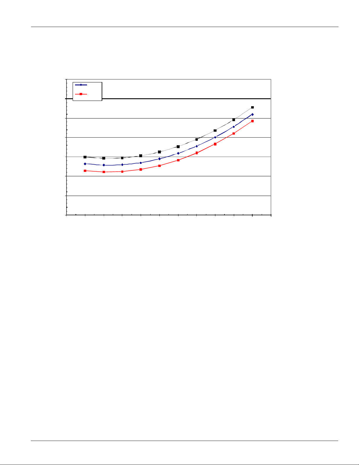
Up to 600 Tons
Daikin centrifugal chillers up to 600 Tons are equipped with
electronic expansion valves (EXV) and will start and run
with entering
condenser water temperatures as low as shown
in Figure 11 (based on a 10 degree F condenser Delta-T) or
as calculated from the following equation on which the
curves are based
14 Cat 605-5
Page 15
Application Considerations
LChWT
42
LChWT
Min. ECWT = 5.25 + 0.88*(LWT) - DT
FL*
(PLD/100) + 22 *(PLD/1 00)2
ECWT = E nt erin g c ond en ser water te mperat ur e
LWT = Leaving chilled water temperature
DT
FL
= Ch ille d Wate r D elta -T at full l oad
PL D = The pe rc ent ch ille r load poin t to b e chec ked
For example; at 44F LWT, 10 degree F Delta-
water temperature could be as low as 44.5F. This provides excellent operation with watereconomizer systems.
Figure 11: Minimum Entering Condenser Water Temperature (With Electronic Expansion Valve)
Minimum Entering Condenser Water Temperature - 10 F Range
65.0
60.0
55.0
50.0
F
,
T
W
C
E
45.0
40.0
35.0
30.0
0 10 20 30 40 50 60 70 80 90 100 110
44
Percent Load
T, and 50% full load operation, the entering condenser
Cat 605-5 15
side
Page 16

Application Considerations
44
LChW
T
Over 600 Tons
Chillers over approximately 600 Tons are equipped with
thermal expansion valves (TXV) and will start and run with
entering condenser water temperatures as low as calculated by
the following equation and shown in the chart following.
"ECWT = Entering condenser water temperature
"LWT = Leaving chilled water temperature
"DTFL = Chilled Water Delta-T at full load
"PLD = The percent chiller load point to be checked
Min. ECWT = 7.25 + LWT- 1.25* DTFL(PLD/100) +
65. 0
60. 0
55. 0
50. 0
45.0
40. 0
2
Minimu m Ent er ing C ond ens er Wate r Temp er atur e - 10 F R an ge
42
LChWT
22*(PLD/100)
Figure 12: Minimum Entering Condenser Water Temperature (Thermal Expansion Valve)
F
,
T
W
C
E
35. 0
30. 0
0 102030405060708090100110
Percen
t Load
For example; at 44 F LWT, 10 degree F Delta-T, and 50% full
load operation, the entering condenser water temperature could
be as low as 50.5 F. This provides excellent operation with
water-side economizer systems.
Depending on local climatic conditions, using the lowest
possible entering condenser water temperature may be more
costly in total system power consumed than the expected
savings in chiller power would suggest, due to the excessive
fan power required.
Cooling tower fans must continue to operate at 100% capacity
at low wet bulb temperatures. As chillers are selected for lower
kW per ton, the cooling tower fan motor power becomes a
higher percentage
of the total peak load chiller power.
Daikin's Energy Analyzer program can optimize the chiller/
tower operation for specific buildings in specific locales.
Even with tower fan control, some form of water flow control,
such as tower bypass, is recommended.
Condenser water temperature rise
The industry standard of 3 gpm/ton or about a 9.5-degree
delta-T works well for most applications. Reducing condenser
water flow to lower pumping energy will increase the water
temperature rise, resulting in an increase in the compressor's
condensing pressure and energy consumption. This is usually
not a productive strategy.
System analysis
Although Daikin is a proponent of analyzing the entire
system, it is generally effective to place the
chiller in the most
efficient mode because it is, by far, a larger energy consumer
than pumps. The Daikin Energy Analyzer program is an
excellent tool to investigate the entire system efficiency,
quickly and accurately. It is especially good at comparing
different system types and operating parameters. Contact your
local Daikin sales office for assistance on your particular
application.
For Best Chiller Efficiency
The designer must determine the proper chiller efficiency for a
given application. The most efficient chiller is not always the
best. A life cycle analysis (as performed by Daikin's Energy
Analyzer program, for example) is the only way to be sure of
the best selection. Utility costs, load factors, maintenance
costs, cost of capital, tax bracket; in other words, all the factors
affecting owning cost, must be considered.
Generally, the attempts to save the last few full load kW are
very costly. For example, the cost to go from 0.58 to 0.57 kW/
16 Cat 605-5
Page 17
Application Considerations
ton could be very costly because of the large number of copper
tubes that would have to be added to the heat exchangers.
Table 7:
Vessel Activity Example
Evaporator
Evaporator
Evaporator Lower flow rates
Condenser
Condenser
Higher leaving water
Temperatures
Higher water temperature
drops
Lower entering water
temperature
Higher flow rates (3.0 gpm/
ton or higher)
44F instead of 42F
12°F instead of 10°F
2.4 gpm/ton instead of
3.0 gpm/ton
84F instead of 85F
3.0 gpm/ton instead of
2.5 gpm/ton
Mixing Single and Dual Compressor Chillers
WDC dual compressor chillers excel at part load operation,
while single compressor chillers usually have better full load
efficiency. A good chiller plant strategy is to install one dual
and one or more single compressor units. Run the dual until it
is fully loaded, then switch to the single compressor unit and
run it only at full load, using the dual to trim the load.
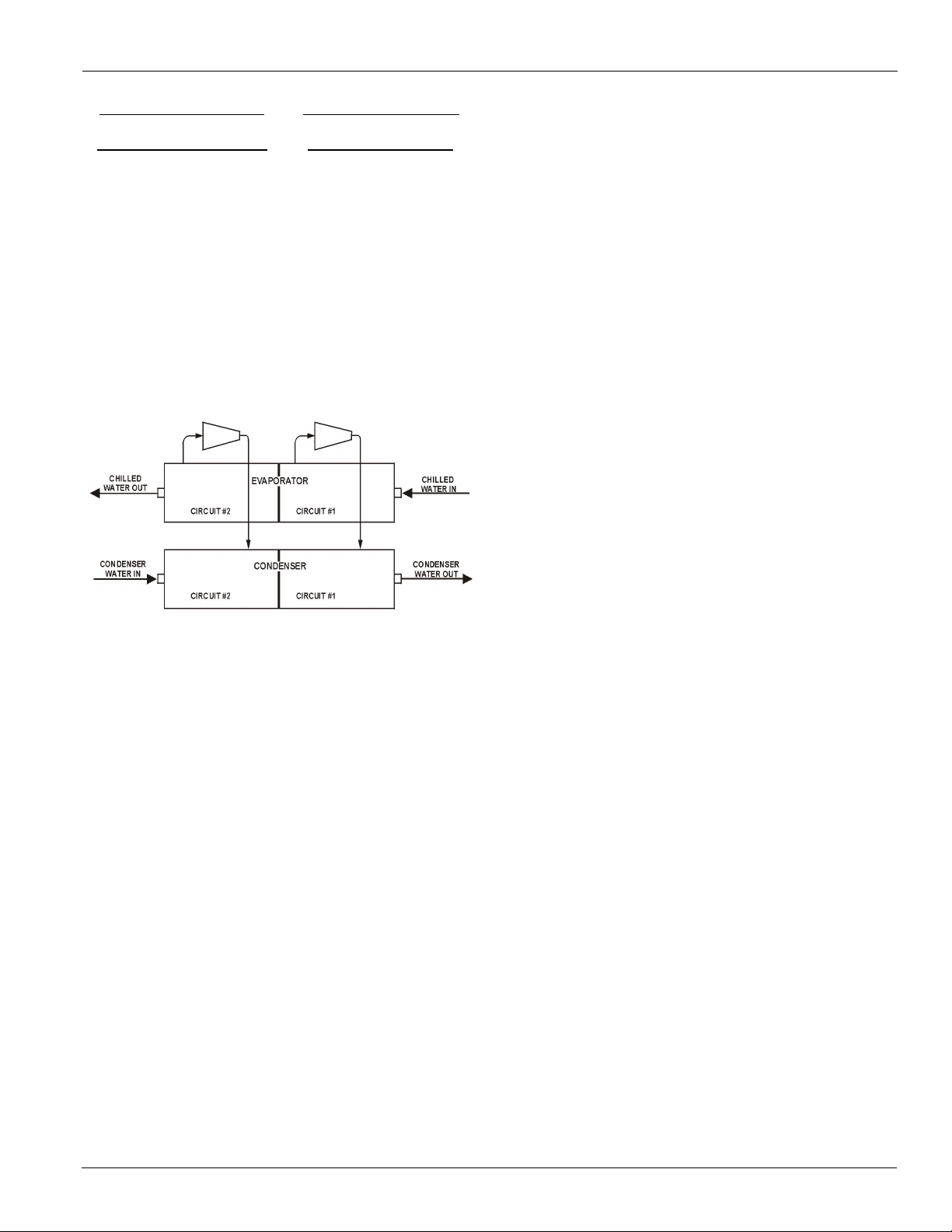
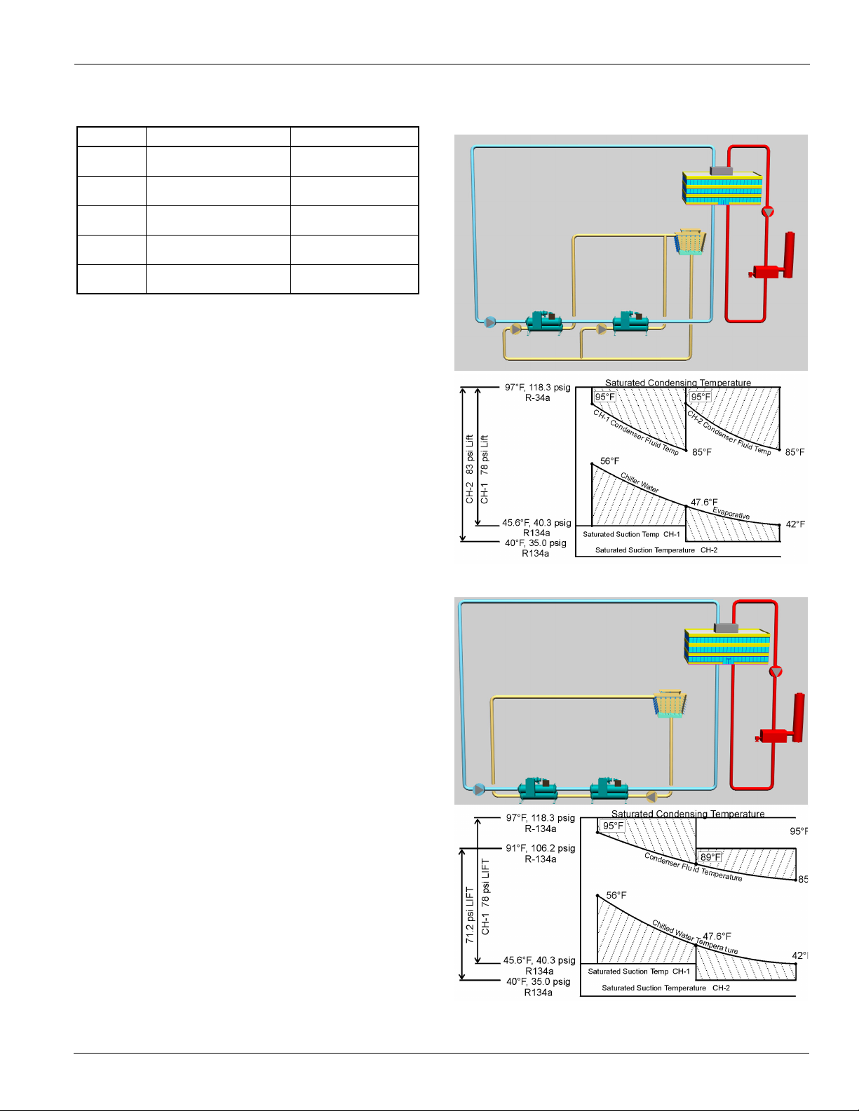
Series Counterflow and Series Parallel Chillers
The design of piping systems can greatly impact chiller
performance. A popular system is to place the evaporators in
series with the chilled water flowing from one evaporator to
the next as shown in Figure 13 and Figure 14. Two different
condenser water piping arrangements can be used. Parallel
flow (Figure 13) divides the total condenser flow between the
two condensers. The counterflow system (Figure 14) puts all
of the condenser water through the condenser of the lag chiller
(chiller producing the coldest evaporator leaving water) and
then through the lead chiller (chiller seeing the warmest
evaporator water temperatures).
tons) combines counterflow design into one unit. See page 6
for details.
Figure 13: Series Parallel Flow
Figure 14: Series Counterflow Flow
Typically, since the lead machine will see the warmest
evaporator water, it will have the greater capacity and larger
portion of the total system evaporator temperature drop. Again
referring to Figure 13 and Figure 14, the lead machine has an
8.4 degree drop (56.0
degree drop (47.6
°F-47.6°F) and the lag machine has a 5.6
°F - 42.0°F).
Condenser water flow is important to overall system
efficiency. With parallel flow (Figure 13), the condensers have
identical flow conditions (95 to 85 degrees in this example)
with the compressor lift shown. With counterflow arrangement
the lift on the lead machine is significantly lower, reducing
compressor work and making the overall system efficiency
about 2% better. Even though the chiller performance is
different, it is good practice to use the same chiller models.
Both the WSC and WDC chillers are suitable for series
counterflow arrangement and include controls specifically
designed for series chillers. For more information, please refer
to Application guide AG -31-003: Chiller Plant Design.
Daikin's model WCC dual compressor chiller (1200 to 2700
Cat 605-5 17
Page 18
Application Considerations
CHILLER
OIL COOLER
STOP
VALVE
STRAI NER
MAX. 40 MESH
SOLENO ID
VA LV E
DRA IN VALVE
OR PLUG
PUMP
OPEN
DRAIN VALVE
OR PLUG
SOL EN OID
VA LVE
OIL COOLE R
STRAINE R
MAX. 40
MESH
DISCHARGE ABOVE
HI GH EST POSSIBLE
WATER LEVEL
Oil Coolers
Daikin centrifugal chillers have a factory-mounted, watercooled oil cooler with a temperature controlled water
regulating v
Cooling water connections are located at the rear of the unit,
near the compressor and are shown on the specific unit
certified drawings. Models WDC 063 through 087 and all
WCC have the cooling water connections in the lower portion
of one tube sheet.
WDC 063, 079, 087, 100 and 126 dual compressor chillers are
equipped as above, but the water piping for the two oil coolers
is factory piped to a common inlet and outlet connection.
Field water piping to the inlet and outlet connections must be
installed according to good piping practices and must include
stop valves to isolate the cooler for servicing. A 1" minimum
cleanable filter (40 mesh maximum) and drain valve or plug
must also be field installed. The water supply for the oil cooler
must be from the chilled water circuit, or from an independent
clean source such as city water. When using chilled water, it is
important that the water pressure drop across the evaporator is
greater than the pressure drop across the oil cooler or
insufficient oil cooler flow will result. If the pressure drop
across the evaporator is less than the oil cooler, the oil cooler
must be piped across the chilled water pump, provided that its
pressure drop is sufficient. The water flow through the oil
cooler will be adjusted by the unit's regulating valve so that the
temperature of oil supplied to the compressor bearings
(leaving the oil cooler) is between 90
C).
43
NOTE: The system must be designed for the highest cooling
water temperature possible, which may occur for a short time
during startup.
alve and solenoid valve for each compressor.
F and 110F (32C and
Table 9: WSC with VFD Oil Cooler Data
Hot
Side
POE
Lub.
Cold Side Water
WSC/HSC 063 - 087
Flow, gpm 9.9 13.4 4.0 2.9 2.3
Inlet Temperature, F 118.0 80.0 65.0 55.0 45.0
Outlet Temp., F 100.0 90.3 99.6 103.1 105.6
Pressure Drop, ft. - 30.5 6.7 4.8 3.6
WSC/HSC 100 - 126
Flow, gpm 15.8 24.4 7.0 5.0 4.0
Inlet Temp., F 120.0 80.0 65.0 55.0 45.0
Outlet Temp., F 100.0 89.8 100.1 103.6 106.2
Pressure Drop, ft. - 30.6 15.7 11.4 9.3
NOTES:
1WDC and WCC units have twice the cooling water flow rate
of the comparable WSC chiller.
2
Pressure drops include valves on the unit.
When supplied with city water, the oil piping must discharge
through a trap into an open drain to prevent draining the cooler
by siphoning. The city water can also be used for cooling
tower makeup by discharging it into the tower sump from a
point above the highest possible water level.
Note: Particular attention must be paid to chillers with variable
chilled water flow through the evaporator. The pressure
drop available at low flow rates can very well be
insufficient to supply the oil cooler with enough water. In
this case an auxiliary booster pump can be used or city
water employed.
Cooling Water Connection Sizes: WDC/WCC 100/126 have 11/2 in. FPT connections, all other WDC and WSCs are 1 in.
FPT.
Figure 15: Oil Cooler Piping Across Chilled Water Pump
Compressors using chilled water for oil cooling will often start
with warm "chilled water" in the system until the chilled water
loop temperature is pulled down. With cooling water in the
F to 55F (4C to 13C) range, considerably less water will
40
R
S
be used and the pressure drop will be greatly reduced. The
following table contains oil cooler data at various inlet water
temperatures.
Table 8: WSC Oil Cooler Data
Hot
Side
POE
Lube
Cold Side Water
WSC 063 - 087
Flow, gpm 9.9 11.9 2.9 2.0 1.54
Inlet Temperature, F 118.0 80.0 65.0 55.0 45.0
Outlet Temp., F 100.0 87.3 94.5 98.3 101.4
Pressure Drop, psi - 4.3 0.3 0.14 0.09
WSC 100 - 126
Flow, gpm 15.8 21.9 5.11 3.5 2.7
Inlet Temperature, F 120.0 80.0 65.0 55.0 45.0
Outlet Temp., F 100.0 87.0 95.0 99.0 102.3
Pressure Drop, psi - 3.78 0.23 0.11 0.07
18 Cat 605-5
Figure 16: Figure 17, Oil Cooler Piping With City Water
R
S
COOLING TOWER
COOLING TOWER MAKEUP
DRA IN
STOP
VALU E
Page 19

Application Considerations
5.0
2
....
2
2
2
1
n
DDD
Common
D
Pumps
Model WSC, WDC and WCC chiller compressor motors
operate at 3600 rpm on 60 Hz power (3000 rpm on 50 Hz).
When VFDs are employed, the hertz/speed can be reduced by
70%. To avoid the possibility of objectionable harmonics in
the system piping, 4-pole, 1800/1500 rpm system pumps
should be used. The condenser water pump(s) must be cycled
off when the last chiller of the system cycles off. This will
keep cold condenser water from migrating refrigerant to the
condenser. Cold liquid refrigerant in the condenser can make
start-up difficult. In addition, turning off the condenser water
pump(s) when the chillers are not operating will conserve
energy.
Include thermometers and pressure gauges at the chiller inlet
and outlet connections and air vents at the high points of
piping. The water heads can be interchanged (end for end),
allowing water connections to be made at either end of the
unit. Use new head gaskets when interchanging water heads.
When water pump noise is objectionable, use rubber isolation
sections at both the inlet and outlet of the pump. Vibration
eliminator sections in the condenser inlet and outlet water lines
are not normally required. Where noise and vibration are
critical and the unit is mounted on spring isolators, flexible
piping and conduit connections are necessary. If not factory
installed, a flow switch or pressure differential switch must be
installed in the leaving chilled water line in accordance with
the flow switch manufacturer's instructions.
Victaulic connections are AWWA C-606 on 14-inch and larger
sizes. Field supply transitions if Victaulic brand AGS®
(Advanced Groove System) type grooves are used on the field
piping.
Filtering and Treatment
Owners and operators must be aware that if the unit is
operating wit
cooling tower is required. Make sure tower blow-down or
bleed-off is operating. Atmospheric air contains many
contaminants, which increases the need for water treatment.
The use of untreated water will result in corrosion, erosion,
slime buildup, scaling, or algae formation. A water treatment
service should be used. Daikin is not responsible for damage
or faulty operation from untreated or improperly treated
water.
Machine Room Ventilation
In the market today, centrifugal c
either hermetic or open type motors. Hermetic motors are
cooled with refrigerant and dissipate their heat through the
cooling tower. On the other hand, open motors circulate
equipment room air across themselves for cooling and reject
the heat to the equipment room. Daikin chillers have hermetic
motors and DO NOT require additional ventilation.
For chillers with open-drive type, air-cooled motors, good
engineering practice dictates that the motor heat be removed to
h a cooling tower, cleaning and flushing the
hillers are available with
prevent high equipment room temperatures. In many
applications this requires a large volume of ventilation air, or
mechanical cooling to properly remove this motor heat.
EXAMPLE: 1000 tons x 0.6 kW/Ton x 0.04 motor heat loss x
0.284 Tons/kW = 7 tons (24 kW) cooling
The energy and installation costs of ventilation or mechanical
cooling equipment must be considered when evaluating
various chillers. For a fair comparison, the kW used for the
ventilation fans, or if mechanical cooling is required, the
additional cooling and fan energy must be added to the open
motor compressor energy when comparing hermetic drives.
Additionally, significant costs occur for the purchase,
installation, and maintenance of the ventilation or air handling
units.
Equipment room ventilation and safety requirements for
various refrigerants is a complex subject and is updated from
time to time. The latest edition of ASHRAE 15 should be
consulted.
Thermal Storage
Daikin chillers are designed for use in thermal storage
systems. The chillers
must be considered. The first is normal air-conditioning
The second condition occurs during the ice making process
when leaving fluid temperatures are in the 22
(-5.6
°C to -3.3°C) range.
The MicroTech II control system will accommodate both
operating points. The ice mode can be started or stopped by an
input signal to the microprocessor from a BAS or through a
chilled water reset signal. When a signal is received to change
from the ice mode to the normal operating mode, the chiller
will shut down until the system fluid temperature rises to the
higher setpoint. The chiller will then restart and continue
operation at the higher leaving fluid temperature. When
changing from normal cooling to the ice mode, the chiller will
load to maximum capacity until the lower setpoint is reached.
Computer selections must be made to check that the chiller
will operate at both conditions. If the "ice mode" is at night,
the pressure differentials between the evaporator and
condenser are usually similar to normal cooling applications.
The leaving fluid temperature is lower, but the condensing
temperature is also lower because the cooling tower water is
colder. If the ice mode can also operate during the day, when
cooling tower water temperatures are high, a proper selection
becomes more difficult because the two refrigerant pressure
differentials are significantly different.
A three-way condenser water control valve is always required.
have two operating conditions that
duty where leaving
evaporator fluid
temperatures range
from 40
(4.4
°F to 45°F
°C to 7.2°C).
°F to 26°F
Cat 605-5 19
Page 20

Application Considerations
Variable Speed Pumping
Variable speed pumping involves changing system water
flow relative to cooling load change
chillers are designed for this duty with two limitations.
First, the rate of change in the water flow needs to be slow, not
greater than 10% of the change per minute. The chiller needs
time to sense a load change and respond.
Second, the water velocity in the vessels must be 3 to 10 fps
(0.91 and
occurs which reduces heat transfer. Above 10 fps (3.0 m/sec),
excessively high pressure drops and tube erosion occur.
These flow limits can be determined from the Daikin
selection program.
We recommend variable flow only in the evaporator because
there is virtually no change in chiller efficiency compared to
constant flow. In other words, there is no chiller energy
penalty. Although variable speed pumping can be done in the
condenser loop, it is usually unwise. The intent of variable
flow is to reduce pump horsepower. However, reducing
condenser water flow increases the chiller's condensing
pressure, increasing the lift that the compressor must overcome
which, in turn, increases the compressor's energy use.
Consequently, pump energy savings can be lost because the
chiller operating power is significantly increased.
Low condenser flow can cause premature tube fouling and
subsequent increased compressor power consumption.
Increased cleaning and/or chemical use can also result.
Vibration Mounting
Every Daikin chiller is run tested and compressor vibration is
measured and limited to a maximum rate
second, which is considerably more stringent than other
available compressors. Consequently, floor-mounted spring
isolators are not usually required. Rubber mounting pads are
shipped with each unit. It is wise to continue to use piping
flexible connectors to reduce sound transmitted into the pipe
and to allow for expansion and contraction.
AHRI Standard 575 Sound Ratings
Sound data in accordance with AHRI Standard 575 for
individual units are available from your local Daikin
representative. Due to the large number of
combinations and variety of applications, sound data is not
included in this catalog.
3.0 m/sec). Below 3 fps (0.91 m/sec), laminar flow
s. Daikin centrifugal
of 0.14 inches per
component
Discharge Line Sound Packages
For extremely sensitive projects, an optional discharge line
sound package is offered consisting of sound insulation
installed on the unit's discharge line. An additional 2 to 4 dbA
reduction normally occurs.
System Water Volume
All chilled water systems need adequate time to recognize a
load change, respond to that load change and stabilize, without
undesirable short cycling of the compressors or loss of control.
In air conditioning systems, the potential for short cycling
usually exists when the building load falls below the minimum
chiller plant capacity or on close-coupled systems with very
small water volumes.
Some of the things the designer should consider when looking
at water volume are the minimum cooling load, the minimum
chiller plant capacity during the low load period and the
desired cycle time for the compressors.
Assuming that there are no sudden load changes and that the
chiller plant has reasonable turndown, a rule of thumb of
"gallons of water volume equal to two to three times the
chilled water gpm flow rate" is often used.
A properly designed storage tank should be added if the
system components do not provide sufficient water volume.
Relief Valves
Relief valve connection sizes are 1-inch
quantity shown in Table 10 for the evaporator and condenser.
In addition, there is a relief valve (3/8 inch flare) on the top of
the oil sump of all units.
All relief valves (including the oil sump) must be piped to the
outside of the building in accordance with ANSI/ASHRAE 15-
2001. The new 2001 standard has revised the calculation
method compared to previous issues.
Twin relief valves, mounted on a transfer valve, are used on
the condenser so that one relief valve can be shut off and
removed for testing or replacement, leaving the other in
operation. Only one of the two valves is in operation at any
time. Where 4 valves are shown, on some large vessels, they
consist of two relief valves mounted on each of two transfer
valves. Only two relief valves of the four are active at any
time.
FPT and are in the
20 Cat 605-5
Page 21

Application Considerations
Figure 17: Typical Vent Piping
Vent piping is sized for only one valve of the set since only one
can be in operation at a time.
Relief Pipe Sizing (ASHRAE Method)
Daikin centrifugal chillers have the following relief valve
settings and discharge capacity:
• WSC/WCC evaporator (1 valve) and condenser (2 valves
piped together to common vent pipe) = 200 psi, 75.5 lb of
air/min
• WDC evaporator (1) = 180 psi, 68.5 lb of air/min
• WDC condenser(2) = 225 psi, 84.4 lb of air/min
• Note: some large condensers have 4 relief valves
Since the pressures and valve size are fixed for Daikin
chillers, the ASHRAE equation can be reduced to the simple
tabl
e shown below.
Table 10: Relief Valve Piping Sizes
Pipe Size inch
(NPT)
Moody Factor
Equivalent
length (ft)
Note: A 1-inch pipe is too small to handle these valves. A pipe
increaser must be installed at the valve outlet.
1.25 1.5 2 2.5 3 4
0.0209 0.0202 0.0190 0.0182 0.0173 0.0163
2.2 18.5 105.8 296.7 973.6 4117.4
Per ASHRAE Standard 15, the pipe size cannot be less than
the relief device. The discharge from more than one relief
valve can be run into a common header, the area of which shall
not be less than the sum of the areas of the connected pipes.
For further details, refer to ASHRAE Standard 15.
The above information is a guide only. Consult local codes
and/or latest version of ASHRAE Standard 15 for sizing data.
Relief valve pipe sizing is based on the discharge capacity for
the given evaporator or condenser and the length of piping to
be run.
Cat 605-5 21
Page 22
Application Considerations
MODEL CODE EXAM PLE: W S C - 063M - AQ - 18S / E2012- E - 2 * A / C1812- B L Y Y - 2 * A Y Y Y R / 134B
Packaged Water Cooled
Centrifugal Chiller
S = Single Compressor
D = D ual Compressor
C = Dual Counterflow
Hermet ic Co mpressor Model
Compressor/Impeller Code
Gear Ratio
Motor/Voltage Code
Evaporator Shell Description
[Diameter (in.), Length (ft.)]
Tube Count Code
Tube Type Code
Number of Passes (1, 2, 3)
Water Inlet Location (R = Right Inlet; L = Left Inlet)
Connection Type
Condenser Shell Description [Diameter (in.), Length (ft.)]
Tube Count Code
Type Type Code
Tube Count Code (Heat Recovery Condenser)
Tube Type Code (Heat Recovery Conderser)
Number of Passes (1, 2, 3)
Water Inlet Location (R = Right Inlet; L = Left Inlet)
Connection Type
Number of Passes (Heat Recovery Condenser)
Water Inlet Location (Heat Recovery Condenser)
Connection Type (Heat Recovery Condenser)
Motor Manufacturer
Refrigeration Type (134 = HFC-134a)
COMPRESSOREVAPORATOR
CONDENSER
R
Figure 18: Chiller Identification (Code String Index)
22 Cat 605-5
Page 23
Electrical Data
Wiring and Conduit
Wire sizes must comply with local and state electrical codes.
Where total amperes require larger conductors than a single
conduit would permit, limited by dimensions of motor terminal
box, two or more conduits can be used. Where multiple
conduits are used, all three phases must be balanced in each
conduit. Failure to balance each conduit will result in
excessive heating of the conductors and unbalanced voltage.
An interposing relay can be required on remote mounted
starter applications when the length of the conductors run
between the chiller and starter is excessive.
Note: On WDC and WCC dual compressor units, dual power
leads are standard, requiring separate power leads properly
sized and protected to each compressor starter or VFD.
Separate disconnects must be used.
Use only copper supply wires with ampacity based on 75°C
conductor rating. (Exception: for equipment rated over 2000
volts, 90°C or 105°C rated conductors shall be used).
Power Factor Correction Capacitors
Do not use power factor correction capacitors with centrifugal
chillers with a compressor VFD. Doing so can cause harmful
electrical resonance in the system. Correction capacitors are
not necessary since VFDs inherently maintain high power
factors.
Control Power
The 115-volt control power can be supplied from the starter or
a transformer (meeting the
requirements of Daikin Starter
Electrical Data
Specification 359999 Rev 29) separate from the starter. Either
source must be properly fused with 25-amp dual element fuses
or with a circuit breaker selected for motor duty. If the control
transformer or other power source for the control panel is
remote from the unit, conductors must be sized for a maximum
voltage drop of 3%. Required circuit ampacity is 25 amps at
115 volts. Conductor size for long runs between the control
panel and power source, based upon National Electrical Code
limitations for 3% voltage drop, can be determined from the
table below.
Control Power Line Sizing
Maximum Length, ft (m)
0 (0) to 50 (15.2) 12 120 (36.6) to 200 (61.0) 6
50 (15.2) to 75 (22.9) 10 200 (61.0) to 275 (83.8) 4
75 (22.9) to 120 (36.6) 8 275 (83.8) to 350 (106.7) 3
Wire Size
(AWG)
Maximum Length, ft (m)
Notes:
1 Maximum length is the distance a conductor will traverse
between the control power source and the unit control
panel.
2 Panel terminal connectors will accommodate up to
number 10 AWG wire. Larger conductors will require an
intermediate junction box.
Starters and VFDs
Information on starters and VFDs can be found in Daikin
Catalog CAT 608.
Wire Size
(AWG)
Cat 605-5 23
Page 24

Electrical Data
NOTES for Following Wiring Diagram
1 Compressor motor starters are either factory mounted
and wired, or shipped separate for field mounting and
wiring. If provided
by others, starters must comply with
Daikin specification 359999 Rev 29. All line and load
side power conductors must be copper.
2 If starters are freestanding, then field wiring between the
starter and the control panel is required. Minimum wire
size for 115
Vac is 12 GA for a maximum length of 50
feet. If greater than 50 feet, refer to Daikin sales office
for recommended wire size minimum. Wire size for 24
Vac is 18 GA. All wiring to be installed as NEC Class 1
wiring system. All 24 Vac wiring must be run in
separate conduit from 115 Vac wiring. Main power
wiring between starter and motor terminal is factoryinstalled when units are supplied with unit-mounted
starters. Wiring of free-standing starter must be wired in
accordance with NEC and connection to compressor
motor terminals must be made with copper wire and
copper lugs only. Control wiring on free-standing starters
is terminated on a terminal strip in the motor terminal
box (not the unit control panel). Wiring from the unit
control panel to the motor terminal is done in the factory.
3 For optional sensor wiring, see unit control diagram. It is
recommended that dc wires be run separately from 115
Vac wiring.
4 Customer furnished 24 or 120 Vac power for alarm relay
coil can be connected between UTB1 terminals 84 power
and 51 neutral of the control panel. For normally open
contacts, wire between 82 & 81. For normally closed
contacts, wire between 83 & 81. The alarm is operator
programmable. The maximum rating of the alarm relay
coil is 25 VA.
5 Remote on/off control of unit can be accomplished by
installing a set of dry contacts between terminals 70 and
54.
6 Evaporator and condenser flow switches are required and
must be wired as shown. If field supplied pressure
differential switches are used then these must be installed
across the vessel and not the pump.
7 Customer supplied 115 Vac, 20 amp power for optional
evaporator and condenser water pump control power and
tower fans is supplied to unit control terminals (UTBI)
85 power / 86 neutral, PE equipment ground.
8 Optional customer supplied 115 Vac, 25 VA maximum
coil rated chilled water pump relay (EP 1 & 2) can be
wired as shown. This option will cycle the chilled water
pump in response to building load.
9 The condenser water pump must cycle with the unit. A
customer supplied 115 Vac 25 VA maximum coil rated
condenser water pump relay (CP1 & 2) is to be wired as
shown.
10 Optional customer supplied 115 Vac, 25 VA maximum
coil rated cooling tower fan relays (CL - C4) can be
wired as shown. This option will cycle the cooling tower
fans in order to maintain unit head pressure.
11 Auxiliary 24 Vac rated contacts in both the chilled water
and condenser water pump starters can be wired as
shown for additional protection.
12 For VFD, Wye-Delta, and solid state starters connected
to six (6) terminal motors, the conductors between the
starter and motor carry phase current and their ampacity
must be based on 58 percent of the motor rated load
amperes (RLA) times 1.25. Wiring of free-standing
starter must be in accordance with the NEC and
connection to the compressor motor terminals shall be
made with copper wire and copper lugs only. Main
power wiring between the starter and motor terminals is
factory-installed when chillers are supplied with unitmounted starters.
13 Optional Open Choices BAS interfaces. The locations
and interconnection requirements for the various
standard protocols are found in their respective
installation manuals, obtainable from the local Daikin
sales office and also shipped with each unit: Modbus
IM 743-0LonWorks IM 735-0BACnet IM 736-0.
14 The "Full Metering" or "Amps Only Metering" option
will require some field wiring when free-standing
starters are used. Wiring will depend on chiller and
starter type. Consult the local Daikin sales office
for information on specific selections.
24 Cat 605-5
Page 25

Figure 19: Typical Field Connection Diagram
SCHEM. 330387903 REV.0E
A
H
C
CP1
CWI-1
A
H
C
CP2
CWI-2
A
H
C
EP1
EWI-1
A
H
C
EP2
EWI-2
NOTE 11
NOTE 11
NOTE 11
NOTE 11
*NOTE 8
*NOTE 8
*NOTE 9
*NOTE 9
(NOTE 6)
COND.
DELTA P.
OR FLOW
SWITCH
*CONDENSER
WATER
PUMP
STARTERS
*CHILLED
WATER
PUMP
STARTERS
(NOTE 6)
EVAP.
DELTA P.
OR FLOW
SWITCH
* REMOTE
ON/OFF
(NOTE 5)
74
55
80
70
86
85
PE
MODE SWITCH
*
54
86
85
73
78
70
EF1
EF1
77
76
75
70
CF1
CF1
81
82(NO)
83(NC)
84
79
A
H
C4
*NOTE 10
527171
53
A
H
C3
*NOTE 10
A
H
C2
*NOTE 10
A
H
C1
*NOTE 10
MJ NOTE 11
MJ NOTE 11
POWER
* NOTE 4
* ALARM RELAY
(NOTE 4)
* COOLING TOWER BYPASS VALUE
* COOLING TOWER VFD
* COOLING
TOWER
FIRST
STAGE
STARTER
NEUTRAL
* NOTE 7
POWER
GND
MICROTECH CONTROL
BOX TERMINALS
UTB1
(115V)
(24V)
0-10-VDC
0-10-VDC
COMMON
* COOLING
TOWER
SECOND
STAGE
STARTER
* COOLING
TOWER
THIRD
STAGE
STARTER
* COOLING
TOWER
FOURTH
STAGE
STARTER
.
L1
L2
L3
CP1
CP2
23(5A)
24(5)
25
1
2
346
11
12
22
GND
VM
W
T1
-COMPRESSOR TERMINALS -
-STARTER LOAD SIDE TERMINALS -
VFD
T6 T2 T4 T3 T5
T1 T2 T3 T4 T5 T6
T1 T2 T3
T4 T5 T6
-COMPRESSOR TERMINALS -
-STARTER LOAD SIDE TERMINALS-
WYE - DE LTA
T2T1
T3
T1
-COMPRESSOR TERMINALS-
-STARTER LOAD SI DE TERMINALS-
SOLID STATE
T6 T2 T4 T3 T5
T1
T3
T1
T2
T3
-STARTER LOAD SIDE TERMINALS-
MEDIUM AND HIGH VOLT AGE
T2
-COMPRESSOR TERMINALS -
NOTE 12
A
1
234
111112
22
MICROTECH
COMPRESSOR
CONTROL
BOX TERMINALS
CTB1
115VAC
PE
L1L2232425
LESS
THAN
30V
OR
24VAC
NOTE 2
NOTE 2
2L1
2L2
2L3
2L1
2L2
2L3
WTC ONLY
MICROTECH
COMPRESSOR
CONTROL
BOX TERMINALS
CTB3
* FIELD SUPPLIED ITEM
NOTE 2
COMPRESSOR
MOTOR
STARTER
(NOTE 1)
UNIT
COMP.
EXPANSION
LEGEND
3303421XX
3303422XX
3303430XX
WCS/WDC
3325787XX
3325788XX
3326512XX
3325789XX
WTC
-LINE-
FOR DC VOLTAGE AND 4-20 MA
CONNECTIONS (SEE NOTE 3)
FOR DETAILS OF CONTROL REFER
TO CONTROL SCHEMATIC
SCHEM. 330387903 REV.0E
CENTRIFUGAL UNI TS
FIELD CONNECTION DIAGRAM
NOTES:
1.
A
H
C
CP1
CWI-1
A
H
C
CP2
CWI-2
A
H
C
EP1
EWI-1
A
H
C
EP2
EWI-2
NOTE 11
NOTE 11
NOTE 11
NOTE 11
*NOTE 8
*NOTE 8
*NOTE 9
*NOTE 9
(NOTE 6)
COND.
DELTA P.
OR FLOW
SWITCH
*CONDENSER
WATER
PUMP
STARTERS
*CHILLED
WATER
PUMP
STARTERS
(NOTE 6)
EVAP.
DELTA P.
OR FLOW
SWITCH
* REMOTE
ON/OFF
(NOTE 5)
74
55
80
70
86
85
PE
MODE SWITCH
*
54
86
85
73
78
70
EF1
EF1
77
76
75
70
CF1
CF1
81
82(NO)
83(NC)
84
79
A
H
C4
*NOTE 10
527171
53
A
H
C3
*NOTE 10
A
H
C2
*NOTE 10
A
H
C1
*NOTE 10
MJ NOTE 11
MJ NOTE 11
POWER
* NOTE 4
* ALARM RELAY
(NOTE 4)
* COOLING TOWER BYPASS VALUE
* COOLING TOWER VFD
* COOLING
TOWER
FIRST
STAGE
STARTER
NEUTRAL
* NOTE 7
POWER
GND
MICROTECH CONTROL
BOX TERMINALS
UTB1
(115V)
(24V)
0-10-VDC
0-10-VDC
COMMON
* COOLING
TOWER
SECOND
STAGE
STARTER
* COOLING
TOWER
THIRD
STAGE
STARTER
* COOLING
TOWER
FOURTH
STAGE
STARTER
.
L1
L2
L3
CP1
CP2
23(5A)
24(5)
25
1
2
346
11
12
22
GND
VM
W
T1
-COMPRESSOR TERMINALS -
-STARTER LOAD SIDE TERMINALS -
VFD
T6 T2 T4 T3 T5
T1 T2 T3 T4 T5 T6
T1 T2 T3
T4 T5 T6
-COMPRESSOR TERMINALS -
-STARTER LOAD SIDE TERMINALS-
WYE - DE LTA
T2T1
T3
T1
-COMPRESSOR TERMINALS-
-STARTER LOAD SI DE TERMINALS-
SOLID STATE
T6 T2 T4 T3 T5
T1
T3
T1
T2
T3
-STARTER LOAD SIDE TERMINALS-
MEDIUM AND HIGH VOLT AGE
T2
-COMPRESSOR TERMINALS -
NOTE 12
A
1
234
111112
22
MICROTECH
COMPRESSOR
CONTROL
BOX TERMINALS
CTB1
115VAC
PE
L1L2232425
LESS
THAN
30V
OR
24VAC
NOTE 2
NOTE 2
2L1
2L2
2L3
2L1
2L2
2L3
WTC ONLY
MICROTECH
COMPRESSOR
CONTROL
BOX TERMINALS
CTB3
* FIELD SUPPLIED ITEM
NOTE 2
COMPRESSOR
MOTOR
STARTER
(NOTE 1)
UNIT
COMP.
EXPANSION
LEGEND
3303421XX
3303422XX
3303430XX
WCS/WDC
3325787XX
3325788XX
3326512XX
3325789XX
WTC
-LINE-
FOR DC VOLTAGE AND 4-20 MA
CONNECTIONS (SEE NOTE 3)
FOR DETAILS OF CONTROL REFER
TO CONTROL SCHEMATIC
Electrical Data
S SUPPLIED TO UNIT CONTROL TERMINALS (UTB1) 85 POWER / 86 NEUTRAL , PE EQUIPMENT GROUND.
IS SUPPLIED TO UNI T CONTROL TERMINALS (UTB1) 85 POWER / 86 NEUTRAL, PE EQUIPMENT GROUND.
I
CONDENSER WATER PUMP RELAY (CP1 & 2 ) IS TO BE WIRED AS SHOWN. UNITS WITH F REE COOLING MUST HAVE CONDENSER
SHOWN. THIS OPTIONAL WILL CYCLE THE CHILLED WATER PUMP IN RESPONSE TO CHILLER DEMAND.
CONDENSER WATER PUMP RELAY (CP1 & 2 ) IS TO BE WIRED AS SHOWN. UNITS WITH F REE COOLING MUST HAVE CONDENSER
WATER ABOVE 60° BEFORE STARTING.
SHOWN. THIS OPTIONAL WILL CYCLE THE CHILLED WATER PUMP IN RESPONSE TO CHILLER DEMAND.
8. OPTIONAL CUST OMER SUPPLIED 115 VAC 25 VA MAXIMUM COIL RATED CHILLED WATER PUMP RELAY (EP1 & 2) M AY BE WIRED AS
8. OPTIONAL CUST OMER SUPPLIED 115 VAC 25 VA MAXIMUM COIL RATED CHILLED WATER PUMP RELAY (EP1 & 2) M AY BE WI RED AS
WATER ABOVE 60° BEFORE STARTING.
9. THE CONDENSER WATER PUMP MUST CYCL E WITH THE UNIT. A CUSTOMER SUPPLIED 1 15 VAC 25 VA MAXIMUM COIL RATED
9. THE CONDENSER WATER PUMP MUST CYCL E WITH THE UNIT. A CUSTOMER SUPPLIED 1 15 VAC 25 VA MAXIMUM COIL RATED
and and 200 VA200 VACC 115115IIFF ST STARARTTEERS ARRS ARE FE FRREE STEE STANDIANDI NGNG,, TTHHEN FEN FIIELELD WD WII RIRINGNG BETBETWWEENEEN T THHE STE STARARTTEER AND R AND TTHHE CONTE CONTROLROL PANE PANE LL I ISS REQU REQUII RREEDD.. MIMINNIIMUM WMUM WIIRREE SI SI ZZ EE F FOORR V VAAC C
EE STANDING
7. CUSTOMER SUPPLIED 115 VAC 20 AMP POWER FOR OPTIONAL EVAP AND COND WATER PUMP CONTROL POWER AND TOWER FANS
7. CUSTOMER SUPPLIED 115 VAC 20 AMP POWER FOR OPTIONAL EVAP AND COND WATER PUMP CONTROL POWER AND TOWER FANS
CONNECTED TO SIX (6) TERMINAL MOTORS. THE CONDUCTORS BETWEEN THE
CONNECTED TO SIX (6) TERMINAL MOTORS. THE CONDUCTORS BETWEEN THE
UNIT HEAD PRESSURE.
C3 – C4 OPTIONAL) MAY BE WI RED AS SHOWN. THIS OPTION WILL CYCLE T HE COOLING TOWER FANS IN ORDER TO MAINTAI N
C3 – C4 OPTIONAL) MAY BE WI RED AS SHOWN. THIS OPTION WILL CYCLE T HE COOLING TOWER FANS IN ORDER TO MAINTAI N
UNIT HEAD PRESSURE.
11. AUXILI ARY 24 VAC RATED CONTACTS IN BOTH THE CHILL ED WATER AND CONDENSER WATER PUMP STARTERS SHOULD BE
11. AUXILI ARY 24 VAC RATED CONTACTS IN BOTH THE CHILL ED WATER AND CONDENSER WATER PUMP STARTERS SHOULD BE
10. OPTIONAL CUSTOMER SUPPLIED 115 VAC 25 VA MAXIMUM COI L RATED COOLING TOWER FAN RELAYS (C1 – C2 ST ANDARD,
10. OPTIONAL CUSTOMER SUPPLIED 115 VAC 25 VA MAXIMUM COI L RATED COOLING TOWER FAN RELAYS (C1 – C2 ST ANDARD,
NALS MUST BE MADE WITH COPPER WIRE AND COPPER L UGS ONLY.
NALS MUST BE MADE WITH COPPER WIRE AND COPPER L UGS ONLY.
THE STARTER AND MOTOR TERMI NALS IS FACTORY INSTALLED WHEN CHILL ERS ARE SUPPLIED WITH UNIT MOUNTED STARTERS.
COMPRESSOR MOTOR TERMINALS SHAL L BE MADE WITH COPPER WIRE AND COPPER LUGS ONLY. MAIN POWER WI RING BETWEEN
WIRED AS SHOWN AND REMOVE MJ.
AMPERES (RLA). WI RING OF FREE STANDING STARTER MUST BE I N ACCORDANCE WITH THE NEC AND CONNECTION TO THE
WIRED AS SHOWN AND REMOVE MJ.
THE STARTER AND MOTOR TERMI NALS IS FACTORY INSTALLED WHEN CHILL ERS ARE SUPPLIED WITH UNIT MOUNTED STARTERS.
STARTER AND MOTOR CARRY PHASE. CURRENT AND SELECTION SHALL BE BASED ON 58 PERCENT OF THE MOT OR RATED LOAD
COMPRESSOR MOTOR TERMINALS SHAL L BE MADE WITH COPPER WIRE AND COPPER LUGS ONLY. MAIN POWER WI RING BETWEEN
STARTER AND MOTOR CARRY PHASE. CURRENT AND SELECTION SHALL BE BASED ON 58 PERCENT OF THE MOT OR RATED LOAD
AMPERES (RLA). WI RING OF FREE STANDING STARTER MUST BE I N ACCORDANCE WITH THE NEC AND CONNECTION TO THE
12. FOR VFD, WYE- DELTA, AND SOLID STATE STARTERS
12. FOR VFD, WYE- DELTA, AND SOLID STATE STARTERS
CENTRIFUGAL UNI TS
FIELD CONNECTION DIAGRAM
RIINNG MUSTG MUST BE RUN I BE RUN INN SEPARAT SEPARATE CONE CONDDUUIITT F FRROM OM 111155 VAC A VAC AND ND
R
I
I
COMPRCOMPRESSOR MESSOR MOOTTOOR STR STAARRTTEERS ARRS ARE EIE EITTHHERER F FAACTCTORYORY MOU MOUNNTTEED AND WD AND WIIRREED OR SHD OR SHIIPPED SEPPED SEPARATPARATEE F FOOR FR FIIELELD D MOUNTMOUNTIINNGG AND W AND WIIRRIINGNG.. IIFF PR PROVIOVIDDEED BD BYY OT OTHERSHERS
NOTES:
VAC W
VAC W
0
0
2
2
L
L
AL
AL
.
.
EM
EM
ST
ST
NG SY
NG SY
I
I
R
R
I
I
W
W
1
1
ASS
ASS
NEC CL
NEC CL
S
S
D A
D A
E
E
L
L
AL
AL
ST
ST
N
N
BE I
BE I
O
O
T
T
NG
NG
RI
RI
I
I
CONDUCONDUCCTTOOR RATR RATIINGNG.. ( (EEXCXCEPTEPTII ONON:: FFOOR EQUIR EQUIPPMMENTENT RA RATTEED OVERD OVER 2 200 0000 VOLVOLTTSS,, 9900°°CC O ORR 11 0055°°C RC RAATTEED COND CONDUCTDUCTOORSRS SHALSHALLL BE BE USED USED..
STSTARTARTEERS MUSTRS MUST COMPL COMPLYY WWIITTHH MCQ MCQUAY SPECUAY SPECIIFFII CATCATIIONON 335599AA999999.. ALALLL L LIINE NE AND LAND L OOADAD SI SIDE POWER CONDDE POWER COND UCTUCTOORS MRS MUUSTST BE C BE COPPEROPPER,, WIWITTHH AMPA AMPACICITYTY B BAASESEDD O ONN 75° 75°CC
W
W
IISS 1122 G GAA.. FFOOR A R A MAXI MAXIMUMMUM L LEENGTNGTHH OFOF 5500 F FEEETET.. IIFF G GRREAEATTEER TR THHANAN 5 500 FFEEETET R R EEFFEER TR TOO MCQUAY MCQUAY FFOOR RECOR RECOMMENDMMENDEEDD
WIRING BETWEEN STARTER AND MOT OR TERMINAL IS FACTORY INSTALLED WHEN UNI TS ARE SUPPLIED WITH UNIT MOUNTED STARTERS. WIRING OF FREE STANDING
WIRING BETWEEN STARTER AND MOTOR T ERMINAL IS FACTORY INSTALLED WHEN UNI TS ARE SUPPLIED WITH UNIT MOUNTED STARTERS. WIRING OF FR
STARTER MUST BE WIRED I N ACCORDANCE WITH NEC AND CONNECTION TO COMPRESSOR MOTOR T ERMI
STARTER MUST BE WIRED I N ACCORDANCE WITH NEC AND CONNECTION TO COMPRESSOR MOTOR TERMI
2.
2.
1.
Cat 605-5 25
ALARM RELAY COIL MAY BE CONNECTED BET WEEN UTB1 TERMINALS 84 POWER AND 81 NEUTRAL OF THE CONTROL
ALARM RELAY COIL MAY BE CONNECTED BET WEEN UTB1 TERMINALS 84 POWER AND 81 NEUTRAL OF THE CONTROL
TC UNITS AND OPTI ONAL ON WSC & WDC . PADDLE SWITCHES MAY ALSO BE FIELD INSTAL LED IF DESIRED.
RATING OF THE ALARM REL AY COIL IS 25VA.
PANEL. FOR NORMALLY OPEN CONTACT S WIRE BETWEEN 82 & 81. FOR NORMALLY CLOSED WIRE BETWEEN 83 & 81. THE ALARM IS OPERATOR PROGRAMMABLE. MAXIMUM
RATING OF THE ALARM REL AY COIL IS 25VA.
PANEL. FOR NORMALLY OPEN CONTACT S WIRE BETWEEN 82 & 81. FOR NORMALLY CLOSED WIRE BET WEEN 83 & 81. THE ALARM IS OPERATOR PROGRAMMABLE. MAXIMUM
DIFFERENTIAL SWITCHES ARE USED THEN THESE MUST BE INSTALLED ACROSS THE VESSEL AND NOT THE PUMP . FACTORY MOUNTED FLOW SWITCHES ARE STANDARD
ON WTC UNITS AND OPTIO NAL ON WSC & WDC. PADDLE SWITCHES MAY ALSO BE FIELD INSTALL ED IF DESIRED.
DIFFERENTIAL SWITCHES ARE USED THEN THESE MUST BE INSTALLED ACROSS THE V ESSEL AND NOT THE PUMP. FACTORY MOUNTED FLOW SWI TCHES ARE STANDARD
4. A CUSTOMER FURNISHED 24 OR 120 VAC POWER FOR
3. FOR OPTIONAL S ENSOR WIRING SEE UNIT CONTROL DIAGRAM. I T IS RECOMMENDED THAT DC WIRES BE RUN SEPARATELY FROM 155 V AC AND 200 VAC WIRING.
4. A CUSTOMER FURNISHED 24 OR 120 VAC POWER FOR
3. FOR OPTIONAL S ENSOR WIRING SEE UNIT CONTROL DIAGRAM. I T IS RECOMMENDED THAT DC WIRES BE RUN SEPARATELY FROM 155 VAC AND 200 VAC WIRING.
ON W
6. EVAPORATOR AND CONDENSER FLOW SWI TCHES ARE REQUIRED. FIELD I NSTALLED FLOW SWITCHES MUST BE WIRED AS SHOWN. I F FIELD SUPPLIED PRESSURE
6. EVAPORATOR AND CONDENSER FLOW SWI TCHES ARE REQUIRED. FIELD I NSTALLED FLOW SWITCHES MUST BE WIRED AS SHOWN. IF FIELD SUPPLIED PRESSURE
5. REMOTE ON/OFF CONTROL OF UNIT CAN BE ACCOMPLISHED BY INSTALL ING A SET OF DRY CONTACTS BETWEEN TERMINALS 70 AND 54 .
5. REMOTE ON/OFF CONTROL OF UNIT CAN BE ACCOMPLISHED BY INSTALL ING A SET OF DRY CONTACTS BETWEEN TERMINALS 70 AND 54 .
Page 26

Starters and VFDs
0.337
0.365
0.403
0.505
0 0.1 0.2 0.3 0.4 0.5 0.6
WDC w/ VFD
WSC w/ VFD
WDC
WSC
Model
IPLV
Starters and VFDs
Motor Starters
Daikin has a wide variety of starter types and options to fit
virtually all applications. The specifics of the final selection
of size, enclosure, and options are covered in the catalog Cat
Starter available on www.DaikinApplied.com . Please consult
the local Daikin sales office or the starter catalog for details.
This section contains a general overview only.
Mounting Options, Low Voltage, 200 to 600 Volts
Factory-mounted
Starters are furnished, mounted and wired in the factory. Due
to shipping width limitations, the starters for WSC 100
through 126 are shipped loose with cable kits and mounting
brackets for field installation on the unit by others.
Freestanding
Furnished by Daikin and shipped to the job site for setting and
wiring by others.
Starters by others
Starters furnished by others must meet Daikin Specification
359999 Rev 29, available from the local Daikin sales
office. The starters are furnished and installed by others.
Table 11: Low Voltage Starter Mounting Options
Size
WSC/WDC 063-087 X X
WSC/WCC 100-126 X X
WDC 100-126 X
WCC 100-126 X X
FactoryMounted
X
Free-
Standing
Brackets
& Cables
The traditional method of controlling centrifugal compressor
capacity is by inlet guide vanes. Capacity can also be reduced
by slowing the compressor speed and reducing the impeller tip
speed, providing sufficient tip speed is retained to meet the
discharge pressure requirements. This method is more efficient
than guide vanes by themselves.
In actual practice a combination of the two techniques is used.
The microprocessor slows the compressor (to a fixed
minimum percent of full load speed) as much as possible,
considering the need for tip speed to make the required
compressor lift. Guide vanes take over to make up the
difference in required capacity reduction. This methodology
provides the optimum efficiency under any operating
condition.
Impact of Variable Frequency Drives
The chart below illustrates the relative IPLV efficiencies of
various Daikin options for a typical 500-ton selection. The
chiller cost increases as the efficiency improves.
Figure 20: IPLV Comparison by Model
Mounting Options, Medium Voltage, 2300 to 6000
Volts
All starter types in these voltages are for field setting and
wiring only.
Starter Types and Descriptions
Solid state starters are available for both low and medium
voltages and are similar in construction and features regardless
of voltage. For low voltage application, Wye-Delta Closed
Transition starters are available, in addition to solid state. For
medium voltage application, autotransformer, primary reactor
reduced voltage and across-the-line starters are offered in
addition to solid state.
Variable Frequency Drives (VFD)
A VFD modulates the compressor speed in response to load
and evaporator and condenser pressures. Due to the
outstanding part load efficiency, and despite the small power
penalty attributed to the VFD, the chiller can achieve
outstanding overall efficiency. VFDs really prove their worth
when there is reduced load combined with low compressor lift
(lower condenser water temperatures) dominating the
operating hours.
The IPLV values (defined on page 29) are AHRI Certified
Ratings based on AHRI Standard 550/590, Standard for Water
Chilling Packages Using the Vapor Compression Cycle. Full
load is at 44 F chilled water temperature with 2.4 gpm/ton, 85
F entering condenser water temperatures with 3 gpm/ton. Part
load points of 75%, 50%, and 25% employ condenser water
temperature relief (reduction) per the standard.
26 Cat 605-5
Page 27

General Arrangement
Starters and VFDs
VFD Mounting
VFDs can be factory-mounted on the same units and in the
same location as conventional starters or can be free-standing
as shown below. Dimensions begin on page 30.
Table 12: VFD Mounting Options
Chiller Model
WSC/WDC 063-087 X X
WSC 100-126
WDC 100-126 X
WCC 100-126
1: VFD sizes 15 to 81 (380V-480V) and 30-65 (575V) may be either unit
mounted or free-standing. Larger sizes are free-standing only.
2: Unit mounted in the field option includes interconnecting brackets and
cables shipped with unit.
Unit Mounted
at Factory
X
X X
X
Unit Mounted
in Field
X
X
X
Free-
Standing
X
x
VFDs and Distortion
Despite the many benefits,
applying
VFDs
due
to
care must be taken when
the
impact
th
ey may have on the
that
building’s electrical system. VFDs can cause distortion of
the AC line because they are nonlinear loads; that is, they
don't draw sinusoidal current from the line. They instead
only draw current during the peaks of the AC line. This
flattens the top of the voltage waveform. Most other
modern electronic equipment is also a nonlinear load, but
VFDs tend to have a greater impact because of their large
power demand.
Although harmonics are associated with non-linear loads, it
is extremely rare that VFD generated harmonics are an issue
in systems with a minimum of 5% internal impedance.
Power line harmonic distortion can be a concern for a
number of reasons:
Current harmonics can cause additional heating of
1
transformers, conductors, and switchgear. They can
.
also cause nuisance tripping of circuit breakers and
clearing of fuses.
2
Voltage harmonics may disrupt the operation of
.
devices which require a smooth, sinusoidal voltage
waveform.
3
High-frequency components of voltage distortion can
.
interfere with signals which are transmitted on the AC
power line.
The harmonics of concern are often the 5th, 7th, 11th, and
13th. Even harmonics, harmonics divisible by three, and
harmonics above the 13th harmonic are usually not a
problem for three-phase power systems.
The Daikin Drive Passive filter Package provides a
broader range of harmonic reduction performance than
VFDs which use active rectifiers. This is particularly true
at reduced loads, where VFDs provide the greatest
energy savings.
Current Harmonics
An increase in reactive impedance in front of the VFD helps
reduce the harmonic currents. Reactive impedance can be
added in the following ways:
1 Mount the drive far from the source transformer.
2 Add line reactors.
3 Use an isolation transformer.
Voltage Harmonics
Voltage distortion is caused by the flow of harmonic currents
through a source impedance. A reduction in source impedance
to the point of common coupling (PCC) will result in a
reduction in voltage harmonics. This may be done in the
following ways:
1 Keep the PCC as far from the drives (close to the power
source) as possible.
2 Increase the size (decrease the impedance) of the source
transformer.
3 Increase the capacity (decrease the impedance) of the
busway or cables from the source to the PCC.
4 Make sure that added reactance is downstream (closer to
the VFD than the source) from the PCC.
The IEEE 519 Standard
The Institute of Electrical and Electronics Engineers (IEEE)
has developed a standard that recommends distortion limits
for both power utilities and their customers. The purpose of
these limits is to ensure that the voltage distortion of the
utility’s public power grid is maintained at an acceptable
level.
To accomplish this, IEEE 519 presents recommended
harmonic current distortion limits for utility customers.
These limits are based on the peak demand of the customer.
This is called the Total Demand Distortion (TDD). This
standard provides a sliding scale for the recommended TDD
limit for each utility customer. The greater the demand that a
customer places on the utility, the more stringent the
recommended TDD limits. IEEE 519-2014 clearly states
that the TDD is to be measured at the point where a utility
customer connects to the public utility. It does not apply to
any points inside the customer’s facility; it only applies to
the point where another utility customer could connect to the
public power grid.
If the utility’s customers comply with the TDD limits stated
in IEEE 519-2014, it is then the utility’s responsibility to
provide voltage to its customers that meets the harmonic
voltage recommendations of this standard.
Cat 605-5
27
Page 28

Selection Procedures
Selection Procedures
Many combinations of compressor configuration and
condensers and evaporators are available for a given capacity.
The units range from low first cost and relatively high kW per
ton (COP) to high first cost and low kW per ton (COP). An
example illustration of the performance vs. cost display is
shown below. Optimum unit selection for maximum operating
return on the invested first cost is in the area identified by the
red “X”.
Actual optimum unit selection will vary with building
application and system
hours of operation cannot justify a very low kW per ton (COP)
unit. Applications with high hours of operation will justify
high part load as well as full load efficiency units. For
optimum selection an energy analysis is available through your
local Daikin Sales Representative.
design. Applications with minimal
and performance tolerances of all units that fall within the
scope of the program. All chillers that fall within the scope of
AHRI Standard 550/590 will have an AHRI certification label
at no cost to the owner. Equipment covered includes all watercooled chilling packages rated up to 2500 tons (8793 kW),
operating within the range shown in Table 13, with either an
hermetic or open drive, with electric driven motor not
exceeding 5000 volts, and cooling water (glycol applications
are outside the scope AHRI Standard 550/590). he program
excludes the following applications: air and evaporative cooled
chillers, capacity exceeding 2500 tons (8793 kW), voltages
above 5000 volts, brine and special fluids other than water and
heat recovery units.
Table 13: Application Condition Range of AHRI 550/590
Leaving chilled water temperature:
Entering condenser water
temperature:
40°F to 48°F (4.4°C
to 8.9°C)
60°F to 95°F
(15.6°C to 35°C)
Published certified ratings at AHRI standard rating conditions
(shown in include the following values :
• Capacity, tons (kW)
• Power, kW/ton (COP)
• Pressure drop, ft. of water (kPa)
• Integrated Part Load Value (IPLV) or Non-Standard Part
Load Value (NPLV)
The standard rating conditions are:
Table 14: AHRI Standard Rating conditions
Basic unit selections
All Daikin centrifugal chillers are computer selected to
optimize the cooling output and total kW. Computer selection
allows for the specification
of leaving chilled water
temperature, entering condenser water temperature, evaporator
and condenser flow rates, number of passes, and fouling
factors. Glycol applications can also be specified.
Glycol operation
The addition of glycol to the chilled water system for freeze
protection can be required for special applications. Glycol
solutions are required where the evaporating temperatures are
below 33°F (1°C).
AHRI Certification
Daikin is committed to supplying chillers that perform as
specified. Subsequently ,
Daikin centrifugal chillers are part of
the AHRI Certification program. On-going performance
verification of chiller capacity and power input plus AHRI
certified computerized selection output provide the owner
with the assurance of specified performance.
Scope of Certification Program
AHRI Standard 550/590 for Centrifugal or Screw WaterChilling Packages defines certification and testing procedures
Leaving chilled water temperature:
Evaporator waterside field fouling
allowance:
Chilled water flow rate:
Entering condenser water temperature:
Condenser waterside field fouling
allowance:
Condenser water flow rate:
44°F
(6.7°C)
0.0001 ft
(0.0176 m
2.4 gpm/ton
(0.043 l/s / kW)
85°F
(29.4°C)
0.00025 ft
(0.044 m
3.0 gpm/ton
(0.054 l/s / kW)
2
x hr x°F/BTU
2
x °C/kW)
2
x hr x°F/BTU
2
x °C/kW)
Daikin SelectTools (MST) for Centrifugal Chillers is the
selection program used to custom select and rate chillers for
specific job conditions. It is part of the AHRI certification
program, and the certified program version number and issue
date is listed in the AHRI Directory of Certified Applied AirConditioning Products available at www.ahridirectory.org.
MST ratings are available from your local Daikin Sales
Representative.
Full AHRI 550/590 participation and certification has been an
on-going commitment at Daikin. The AHRI
label affixed to
certified units certifies that the unit will meet the specified
performance. This equipment is certified in accordance with
AHRI Standard 550/590, latest edition,
28 Cat 605-5
Page 29

provided the application ratings are within the scope of the
IPLV/NPLV Defined
Part load performance can be presented in terms of
Integrated Part Load Value (IPLV), which is based on
AHRI standard rating conditions (listed above), or NonStandard Part Load Values (NPLV), which is based on
specified or job site conditions. IPLV and NPLV are based
on the following weighting equation from AHRI 550/590:
Using kW/ton, where:
A = kW/ton (or COP) at 100%
B = kW/ton (or COP) at 75%
C = kW/ton (or COP) at 50%
D = kW/ton (or COP) at 25%
Weighting
The percent of annual hours of operation at the four load
points are as follows:
100% Load at 1% of operating time
75% Load at 42% of operating time
50% Load at 45% of operating time
25% Load at 12% of operating time
Tolerances
The AHRI test tolerance, per AHRI Standard 550/590-98,
for capacity (tons), power input per ton (kW/ton), and heat
balance is:
Where:
FL = Full Load
DTFL = Chilled Water Delta-T at Full Load
This formula results in a 5% tolerance on tons and kW/
ton at the 100% load point and AHRI conditions.
DCBA
IPLVorNPLV
12.0
+
45.0
+
42.0
+
01.0
1
=
%.(.%)
%
Tolerance x FL
DTFLx FL
10 5 0 07
1500
certification program.
Figure 21: IPLV/NPLV Defined
Selection Procedures
Cat 605-5 29
Page 30

Dimensions
Dimensions
Figure 22: WSC063 (160-300 tons/ 560 to 1050 kW) See Drawing Notes page 44
VESSEL CODE OVERALL LENGTH
EVAP COND
E2009 C1809
E2012 C1812
E2209 C2009
E2212 C2012
E2209 C2209
E2212 C2212
E2609 C2209
E2612 C2212
E2609 C2609
E2612 C2612
E3012 C2612
E3009 C2609
1&3-
PASS
AA A B C XY ZDEFG
134
(3404)
169
(4293)
134
(3404)
169
(4293)
134
(3404)
169
(4293)
134
(3404)
169
(4293)
134
(3404)
169
(4293)
175
(4445)
140
6)
(355
2-PASS
128
(3251)
163
(4140)
129
(3277)
164
(4166)
129
(3277)
164
(4166)
129
(3277)
164
(4166)
129
(3277)
164
(4166)
167
(4242)
132
(3353)
HEAD CONN.
BOTH ENDS
(3404)
(4293)
(3404)
(4
(3404)
(4293)
(3404)
(4
(3404)
(4293)
(4445)
(3556)
134
169
134
169
293)
134
169
134
169
293)
134
169
175
140
76
76
76
76
76
76
80
80
86
86
90
91
OVERALL
WIDTH W/O
STARTER
CENTER OF GRAVITY FOOTPRINT
68 (1727)
68 (1727)
68 (1727)
36
(914)17(432)
34
(864)17(432)
34
(864)17(432)
)25(635)
OVERALL
HEIGHT
(1930)42(1067)50(1270)37(940)16(406)
(1930)42(1067)
(1930)42(1067)50(1270)36(914)17(432)
(1930)42(1067)
(1930)42(1067)51(1295)35(889)17(432)
(1930)42(1067)
(2032)46(1168)51(1295)37(940)20(508)
(2032)46(1168)69(1753)35(889)20(508)
(2184)48(1219)51(1295)40(1016)20(508)
(2184)48(1219)69(1753)38(965)21(533)
(2286)53(1346)67(1702)41(1041)21(533)
(2235)52(1321)52(1321)41(1041
113
(2870)
148
(3759)
113
(2870)
148
(3759)
113
(2870)
148
(3759)
113
(2870)
148
(3759)
113
(2870)
148
(3759)
148
(3759)
113
(2870)
111
(2819)42(1067)34(864)
145
(3683)42(1067)34(864)
111
(2819)42(1067)34(864)
14
5
(3683)42(1067)34(864)
111
(2819)42(1067)34(864)
145
(3683)42(1067)34(864)
111
(2819)46(1168)38(965)
14
5
(3683)46(1168)38(965)
111
(2819)48(1219)40(1016)
145
(3683)48(1219)40(1016)
145
(3683)53(1646)45(1143)
111
(2819)56(1422)48(1219)
CONNECTIONS
EVAP
2-PASS
COND
2-PASS
66
66
86
86
88
88
88
88
88
88
10 8
10 8
30 Cat 605-5
Page 31

Figure 23: WSC079/087 (300-600 tons/ 1050 to 2110 kW) See Drawing Notes page 44
Dimensions
VESSEL CODE “A” OVERALL LENGTH
EVAP COND
5
E2209
C2209
5
E2212
C2212
E2609 C2209
E2612 C2212
E2609 C2609
2612 C2612
E
E3009 C2609
E3009 C3009
E3012 C2612
E
C3012
3012
E3609 C3009
E3612 C3012
6
C3612
E3612
1&3
PASS2PASS
AA A B C X YZDEFG
134
5
(3404)
169
5
(4293)
134
(3404)
169
(4293)
134
(3404)
169
(4293)
140
(3556)
140
(3556)
175
(4445)
175
(4
445)
140
(3556)
175
(4445)
175
6
(4445)
129
(3277)
164
(4166)
129
(3277)
164
(4166)
129
(3277)
164
(4166)
132
(3353)
132
(3353)
167
(4242)
7
16
(4242)
133
(3378)
168
(4267)
168
(4267)
HEAD CONN.
BOTH ENDS
134
(3404)
169
(4293)
134
(3404)
169
(4293)
134
(3404)
169
(4293)
140
(3556)
140
(3556)
175
(4445)
175
(4445)
140
(3556)
175
(4445)
175
(4445)
OVERALL
HEIGHT
74
(1880)
74
(1880)
78
(1981)
78
(1981)
83
(2108)
83
(
2108)
88
2235)
93
(2362)
88
(2235)
93
(2362)
94
(2388)
94
(2388)
105
(2667)
OVERALL
WIDTH W/O
STARTER
45
(1143)
45
(1143)
49
(1245)
49
(1245)
52
(1321)
52
(1321)
56
(1422)
58
(1473)
56
(1422)
58
(1473)
74
(1880)
74
(1880)
80
(2032)
CENTER OF GRAVITY FOOTPRINT
50
(1270)35(889)18(457)
68
(1727)34(864)18(457)
51
(1295)40(1016)22(559)
69
(1753)35(889)21(533)
51
(1295)37(940)21(533)
69
(1753)38(965)22(559)
52
(1321)41(1041)25(635)
52
(1321)43(1092)26(660)
69
(1753)40(1016)25(635)
70
(1778)41(1041)26(660)
52
(1321)43(1092)34(864)
70
(1778)41(1041)34(864)
70
(1778)46(1168)38(965)
113
(2870)
(3759)
(2870)
(3759)
(2870)
(3759)
(2870)
(2870)
(3759)
(3759)
(2870)
(3759)
(3759)
111
(2819)45(1173)37(9398)
148
145
(3683)45(1173)37(9398)
113
111
(2819)49(1245)41(1041)
148
145
(3683)49(1245)41(1041)
113
111
(2819)52(1321)441118)
148
145
(3683)52(1321)441118)
113
111
(2819)56(1422)48(1219)
113
111
(2819)58(1473)50(1270)
148
145
(3683)56(1422
148
145
(3683)58(1473)50(1270)
113
111
(2819)74(1880)66(1676)
148
145
(3683)74(1879)66(1676)
148
145
(3683)80(2032)72(1829)
)48(1
219)
CONNECTIONS
EVAP
2-PASS
COND
2-PASS
88
88
88
88
88
88
10 8
10 10
10
10 10
12 10
12 10
12 12
8
Cat 605-5 31
Page 32

Dimensions
Figure 24: WSC100/113/126 (600-1250 tons/ 2100 to4400 kW) See Drawing Notes page 44
VESSEL CODE OVERALL LENGTH
EVAP COND
E3612 C3012
E3612 C3612
E4212 C3612
E4212 C4212
E4812 C4212
E48127C4812
1&3
PASS2PASS
AA A B C XYZDEFG
175
(4445)
(4445)
(4445)
(4445)
(4597)
7
(4597)
175
175
175
181
181
(4267)
(4267)
(4318)
(431
(4445)
(4445)
168
168
170
170
175
175
HEAD CONN
BOTH ENDS
8)
175
(4445)
175
(4445)
175
(4445)
175
(4445)
181
(4597)
181
(4597)
OVERALL
HEIGHT
99
(2515)
99
(2515)
99
(2515)
102
(2591)
106
(2692)
106
(2692)
OVERALL
WIDTH W/O
STARTER
74
(1880)68(1727)47(1194)27(686)
80
(2032)68(1727)46(1168)31(787)
86
(2184)69(1753)45(1143)35(889)
92
(2
337)69(1753)45(1143)37(940)
98
(2489)69(1753)46(1168)421067)
104
(2642)70(1778)46(1168)46(1168)
CENTER OF GRAVITY FOOTPRINT
148
(3759)
(3759)
(3759)
(3759)
(3759)
(3683)
145
(3683)74(1880)66(1676)
148
145
(3683)80(2032)72(1829)
148
145
(3683)86(2184)78(1981)
148
145
(3683)922337)84(2134)
148
145
(3683)982489)90(2286)
145
145
(3683)
104
(2642)96(2438)
CONNECTIONS
(NOTE 10)
EVAP
2-PASS
COND
2-PASS
12 10
12 12
14 12
14 14
18 14
18 18
32 Cat 605-5
Page 33

Figure 25: WDC063 (400-600 tons / 1400-2100 kW) See Drawing Notes page 44
Dimensions
VESSEL CODE OVERALL LENGTH
HEAD CONN WIDTH W/O
BOTH ENDS STARTER
214
(5426)
214
(5426)
214
(5426)
214
(
5426)
214
(5445)
218
(5518)
218
(5544)
218
(5544)
218
(5544)
218
(5544)
221
(5623)
224
(5685)
EVAP COND
E2416 C2416
E2416 C2616
E2616 C2416
E2616 C2616
E3016 C3016
E3616 C3616
1&3
PASS2PASS
AA A B C XY Z D E F G
218
(5544)
218
(5544)
218
(5544)
218
(5544)
221
(5623)
224
(5685)
OVERALL
HEIGHT
80
(2032)
80
(2032)
80
(2032)
80
2)
(203
90
(2280)
106
(2686)
OVERALL
58
(1470)
58
(1470)
58
(1470)
58
(1470)
64
(1619)95(2410)
75
(1886)
CENTER OF GRAVITY FOOTPRINT
91
(2318)36(911)17(425)
91
35
35
40
17¼
(438)
16
(419)
21
(537)
(2324)
(2324)36(911)
(2340)
(895)
91
92
(899)17(435)
(1029)
(2) (2) (2)
199
(5048)
199
(5048)
199
(5048)
199
(5048)
199
(5048)
199
(5048)
196
(4972)58(1470)50(1267)
196
(4972)58(1470)50(1267)
196
(4972)58(1470)50(1267)
196
(4972)58(1470)50(1267)
196
(4972)64(1619)56(1416)
196
(4972)
75
(1886)67(1682)
CONNECTIONS
COND
EVAP
PASS
10 10
12 12
2
2
PASS
88
88
88
88
Cat 605-5 33
Page 34

Dimensions
Figure 26: WDC079/087 (600-1200 tons/ 2100-4220 kW) See Drawing Notes page 44
VESSEL CODE OVERALL LENGTH
HEAD CONN WIDTH W/O
BOTH ENDS STARTER
214
218
218
219
5556)
(5620)
(5696)
(5698)
(5698)
EVAP COND
E3016 C3016
E3616 C3016
E3616 C3616
E4216 C4216
1&3
PASS2PASS
AA A B C XYZDEFG
221
(5620)
(5696)
(5698)
(5698)
224
224
224
(5442)
(5531)
(5531)
(
221
224
224
224
OVERALL
HEIGHT
95
(2413)
100
(2530)
106
(2686)
93
62)
(23
OVERALL
57
(1454)
71
(1808)94(2388)
74
(1886)
(2362)97(2458)
(2369)
(2392)
93
CENTER OF GRAVITY FOOTPRINT
93
44
19
199
196
(4974)57(1453)49(1250)
199
196
(4974)71(1803)63(1600)
199
196
(4974)74(1886)66(1682)
199
196
(4974)93(2343)84(2134)
94
(1127)
(1149)32(803)
(1232)
(1127)47(1172)
45
48
44
(492)
32
(822)
(5050)
(5050)
(5050)
(5050)
CONNECTIONS
COND
EVAP
2
PASS
10 10
12 10
12 12
14 14
2
PASS
34 Cat 605-5
Page 35

Dimensions
Figure 27: WDC100 - 16’ Shells (1200-1700 tons/ 4200-5950 kW) Medium Voltage (<7kV) ONLY (See Drawing Notes page 44)
WDC113 - 16’ shells (1400-1900 tons / 4900-6700 kW) Medium Voltage (<7kV) ONLY (See Drawing Notes page 44)
WDC126 - 16’ shells (1600-2700 tons / 5600-9450 kW) Medium Voltage (<7kV) ONLY (See Drawing Notes page 44)
VESSEL CODE OVERALL LENGTH
1&3 2 HEAD CONN WIDTH W/O
EVAP COND PASS PASS BOTH ENDS STARTER
AA A B C X Y Z DEF G
224
E3616 C3616
E4216 C4216
E4816 C4816
(5692)
224
(5692)
230
(5848)
218
(5528)
219
(5554)
224
(5703)
224
(5692)
224
(5692)
230
(5848)
OVERALL
HEIGHT
105
(2667)
108
(2743)
115
(2921)
OVERALL
95
(2419)93(2353)51(1292)40(1003)
100
(2545)94(2381)50(1254)44(1105)
110
(2792)95(2400)52(1318)51(1292)
CENTER OF GRAVITY
W/O STARTER FOOTPRINT
199
(5050)
(5050)
(5050)
196
(4974)95(2419)87(2216)
199
196
(4974)
199
196
(4974)
100
(2545)92(2342)
110
(2792)
102
(2589)
CONNECTIONS
COND
EVAP
PASS
12 12
14 16
18 18
2
2
PASS
Cat 605-5 35
Page 36

Dimensions
EVAPORATOR
CONDENSER
Y
X
B
D
1.5” FPT OIL COOLER CONNECTI ON
INT ERFA CE PANE L
UNIT
CONTROL
BO X
FOOTPRIN
1
V
Figure 28: WDC100 - 20’ Shells (1200-1700 tons/ 4200-5950 kW) Medium Voltage (<7kV) ONLY (See Drawing Notes page 44)
WDC113 - 20’ Shells (1400-1900 tons / 4900-6700 kW) Medium Voltage (<7kV) ONLY (See Drawing Notes page 44)
WDC126 - 20’ Shells (1600-2700 tons / 5600-9450 kW) Medium Voltage (<7kV) ONLY (See Drawing Notes page 44)
ADJUSTABLE OPERATOR
” FPT VESSEL RELIEF
ALVE CONNECTIONS
A
OUT
IN
OUT
T
Y
Z
IN
C
VESSEL CODE OVERALL LENGTH
EVAP COND
E4220 C4220
E4820 C4820
1&3 2 HEAD CONN WIDTH W/O
PASS PASS BOTH ENDS STARTER
AA A B C X Y Z DEF G
272
(6909)
276
(7010)
267
(6772)
271
(6890)
272
(6909)
276
(7010)
OVERALL
HEIGHT
102
(2591)
110
(2794)
OVERALL
92
(2343)
104
(2648)
CENTER OF GRAVITY FOOTPRINT
117
(2991)46(1165)
118
(3007)49(1238)
36
(921)
43
(1105)
247
(6269)
(6269)
244
(6193)92(2343)84(2140)
247
244
(6193)
(2648)96(2444)
104
CONNECTIONS
EVAP
COND
2
PASS
2
PASS
14 16
18 18
36 Cat 605-5
Page 37

Figure 29: WCC100/113/126 (1200-2700 tons / 4220 to9450 kW) See Drawing Notes page 44
Dimensions
EVAP COND
E3620 C3620
E4220 C3620
E4220 C4220
E4820 C4220
E4820 C4820
OVERALL LENGTH OVERALL
1 PASS
EVAP
AA1B C C1 XYZXYZ
272 1/4 272 1/4 100 3/8 80 1/4 72 1/4 115 48 3/4 30 1/2 115 3/4 47 1/4 30 7/8
(6915) (6915) (2550) (2038) (1835) (2921) (1238) (775) (2940) (1200) (784)
272 1/4 272 1/4 101 7/8 86 1/4 78 1/4 115 3/4 47 1/2 34 1/8 116 1/2 46 1/8 34 1/8
(6915) (6915) (2588) (2191) (1988) (2940) (1207) (867) (2959) (1172) (867)
272 1/4 272 1/4 104 5/8 92 1/4 84 1/4 116 1/4 48 38 117 1/4 45 7/8 38 3/4
(6915) (6915) (2658) (2343) (2140) (2953) (1219) (965) (2978) (1165) (984)
278 1/4 272 1/4 108 1/4 98 1/4 90 1/4 116 3/4 49 40 3/4 117 1/2 47 1/2 40 7/8
(7068) (6915) (2750) (2496) (2292) (2965) (1245) (1035) (2985) (1207) (1038)
278 1/4 278 1/4 110 3/8 104 1/4 96 1/4 117 3/8 48 7/8 45 1/2 118 47 3/8 45 5/8
(7068) (7068) (2804) (2648) (2445) (2981) (1241) (1156) (2997) (1203) (1159)
1 PASS
COND
UNIT
HEIGHT
OVERALL
WIDTH W/O
STARTERS
WIDTH
MTG. HOLES
ON FOOT
CENTER OF GRAVITY
(SHIPPING)
CENTER OF GRAVITY
(OPERATING)
Cat 605-5 37
Page 38

Dimensions
(A9)
(A10)
(A7) and (A8)
(Z6)
(Z7)
(Z8)
(Z9)
(A5)
(A6)
6.20
157
(C)
CONDENSER
EVAPORATOR
Z
X
TOP VIEW
3/8-INCH FLARE[9MM]
OIL PUMP RELIEF
VALVE TYPE.(2X)
UNIT CONTROL BOX
(MICRO TECH II)
ADJUSTABLE OPERATOR
INTERFACE TOUCH-SCREEN
PANEL (REMOVED FOR SHIPPING)
6
TERMINAL BOXES
ARE TAKEN OFF
DURING SHIPPING
TYP.2X
(Y3)
TYP.2X
(Y2)
(B)
(E) REF.
(A)
EVAPORATOR
CONDENSER
FRONT VIEW
1.00-INCH FPT [25MM]
RELIEF VALVE ON
BACKSIDE OF UNIT
TYP.(2X)
1.00-INCH FPT [25MM]
RELIEF VALVE
TYP.(2X)
5
5
X
Z
13
7, 11
3, 11
WDC UNIT INFO
333658601 00 NONE
DRAWING NUMBER REV. SCALE
Figure 30: WDC 100/113/126 (Higher Voltage Models - 10/11kV only) continued next page
Note: This drawing for high-voltage models only. See drawing notes Figure 36, page 44.
38 Cat 605-5
Page 39

40.20
TYP. 2X
1021
(Y6)
(Z4)
(Z5)
4.00
TYP.
102
COMPRESSOR
MOTOR TYP.2X
COND
EVAP
Y
Z
1.50-INCH FPT [25mm]
OIL COOLER
CONNECTIONS
LEFT VIEW
7, 15, 16
8
(D)
(F)
(G)
(E)
17.35
TYP. 2X
441
38.18
TYP. 2X
970
X
Z
COMPRESSOR MOTOR
TERMINAL BOX - TYP.2X
TOP VIEW MOUNTING
COMPRESSOR #1 COMPRESSOR #2
7, 15, 16
(Z3)
(Y7)
4.00
102
(Y4)
(Y5)
(Z1)
(Z2)
Y
Z
EVAP
COND
IN
OUT
OUT
IN
RIGHT VIEW
WDC UNIT INFO
333658601 00 NONE
DRAWING NUMBER REV. SCALE
Figure 31: WDC 100/113/126 (Higher Voltage Models - 10/11kV only) continued
Dimensions
Note: This drawing for high-voltage models only. See drawing notes Figure 36, page 44.
Cat 605-5 39
Page 40

Dimensions
WDC UNIT INFO
333658601 00 NONE
DRAWING NUMBER REV. SCALE
Figure 32: WDC 100/113/126 High-Voltage Models (10/11kV) Dimension Details
Note: This drawing for high-voltage models only. See drawing notes Figure 36, page 44.
40 Cat 605-5
Page 41

Figure 33: WCC 100/113/126 Higher Voltage Models (10/11kV) only (continued on next page)
(A8)
(A7)
(A10)
(A9)
TYP.2X
(Z7)
TYP.2X
(Z8)
(C)
CONDENSER
EVAPORATOR
Z
X
CIRCUIT #1
CIRCUIT #2
UNIT CONTROL BOX
(MICRO TECH II)
#1 #2
3/8-INCH FLARE[9MM]
OIL PUMP RELIEF
VALVE TYPE.(2X)
TOP VIEW
6
ADJUSTABLE
OPERATOR
INTERFACE TOUCHSCREEN PANEL
(REMOVED FOR
SHIPPING)
TERMINAL BOXES
ARE TAKEN OFF
DURING SHIPPING
Y
X
(A5)
(A6)
(E) REF.
6.20
157
(B)
TYP.2X
(Y3)
TYP.2X
(Y2)
(A3)
(A4)
(A)
EVAPORATOR
CONDENSER
CIRCUIT #1 CIRCUIT #2
1.00-INCH FPT [25MM]
RELIEF VALVE ON
BACKSIDE OF UNIT TYP.(2X)
1.00-INCH FPT
[25MM]
RELIEF VALVE
TYP.(2X)
FRONT VIEW
7, 11
5
13
5
3, 11
WCC UNIT INFO
333658501 00 NONE
DRAWING NUMBER REV. SCALE
Dimensions
Note: This drawing for high-voltage models only. See drawing notes Figure 36, page 44.
Cat 605-5 41
Page 42

Dimensions
(Y6)
40.20
TYP.2X
1021
(Z4)
(Z5)
4.00
102
COMPRESSOR MOTOR TYP.2X
COND
EVAP
IN
OUT
Y
Z
LEFT VIEW
8
1.50-INCH FPT [25mm]
OIL COOLER
CONNECTIONS
7, 15, 16
38.18
TYP.2X
970
17.35
TYP. 2X
441
4.00
TYP.
102
(E)
(D)
(G)
(F)
X
Z
#1 #2
COMPRESSOR MOTOR
TERMINAL BOX - TYP.2X
TOP VIEW MOUNTING
7, 15, 16
4.00
102
(Z6)
(Y7)
(Y5)
(Y4)
(Z1)
(Z2)
Y
Z
EVAP
COND
IN
OUT
RIGHT VIEW
WCC UNIT INFO
333658501 00 NONE
DRAWING NUMBER REV. SCALE
Figure 34: WCC 100/113/126 Higher Voltage Models (10/11kV) only (continued)
Note: This drawing for high-voltage models only. See drawing notes Figure 36, page 44.
42 Cat 605-5
Page 43

Figure 35: WCC 100/113/126 High-Voltage Models (10/11kV) Dimension Details
WCC UNIT INFO
333658501 00 NONE
DRAWING NUMBER REV. SCALE
Dimensions
Note: This drawing for high-voltage models only. See drawing notes Figure 36, page 44.
Cat 605-5 43
Page 44

Dimensions
WCC-WDC UNIT INFO
333658701 00 NONE
DRAWING NUMBER REV. SCALE
General Drawing Notes:
1 Drawings included in this section are for rough layout
purposes only. Detailed certified drawings, as pdf files
or paper copies,
are available from the local Daikin
sales office. Do not use catalog drawings for final
construction.
2 Dimensions in inches (mm). A 1-inch manufacturing
tolerance must be accounted for in the design and
installation process. Final connections must allow for
.500 inch [12.7mm] manufacturing tolerances. See
Physical Data and Weights section for component and
unit weights.
3 The connections shown are for one possible default
configuration; your unit may be configured differently.
Orientation (left/right) is determined while facing the
control panel. Certain WSC models with a 2-pass
configuration and copper tubing may have an "over/
under" connection configuration on the evaporator.
Consult the Certified Drawings sheet for exact
configuration and detailed dimensions of water, oil
cooler, and relief valve connections.
Figure 36: WDC & WCC Drawing Notes
4 Allow three (3) feet of service access on all four sides,
plus allow the length of the tube plus two feet on one end
for tube removal. The last two numbers in the vessel
code are the tube length in feet. The NEC may require
more than 3 feet clearance in front of control panels or
starting equipment depending voltage and layout.
5 E2209/C2209 and E2212/C2212 available on WSC079
only.
6 E3612/C3612 combination available on WSC 087 only.
7 E4812/C4812 available on WSC 126 only.
8 The optional unit-mounted starter is shipped separate for
field mounting, brackets and interconnecting cables are
shipped with the unit.
9 The adjustable control interface panel is shipped un-
mounted from the unit. When mounted, it can be folded
back within the confines of the unit width and height and
still be viewable.
10 Victaulic connections 14-inch and larger are AWWA C-
606. Field piping using the Victaulic brand AGS®
groove system will require a field-supplied transition.
44 Cat 605-5
Page 45

Figure 37: WCC Head Connection Dimensions - See Notes
Dimensions
EVAPORATOR HEADS
A2 Y4 Z1
EVAP COND
E3620 C3620
E4220 C362
E4220 C422
E4820 C422
E4820 C482
NOTES:
CONNECTIONS
0
0
0
0
1 PASS
16.00 14 1/4 46 1/8 16 16.00
(406) (362) (1172) (406) (406) (362) (572) (1426)
20.00 14 1/4 43 1/8 19 16.00
(508) (362) (1096) (483) (406) (362) (572) (1578)
20.00 14 1/4 45 7/8 19 20.00
(508) (362) (1165) (483) (508) (362) (641) (1654)
24.00 17 1/4 46 7/8 22 20.00
(610) (438) (1191) (559) (508) (362) (641) (1807)
24.00 17 1/4 49 22 24.00
(610) (438) (1245) (559) (610) (438) (718) (1883)
1 All dimensions are in Inches and [Millimeters] unless noted otherwise.
2 Final connections must allow for .500 inch [12.7mm] manufacturing
tolerances.
3 1.00-inch FPT [25.4 mm] evaporator and condenser relief valves must
be piped per ANSI / ASHRAE 15. Number of relief valves is 2 per
evaporator (1 each circuit) and 4 per condenser (2 each circuit).
4 .375 inch [9 mm] oil pump relief valve, 1 per oil pump must be piped
per ANSI / ASHRAE 15.
5 243 inches is required at either end of the tube sheet for tube
maintenance. 36 inches [914 mm] is recommended on all other sides
and top for service clearance.
6 1.50-inch FPT [38 mm] oil cooler water connections.
7 3.25-inch [95 mm] diameter lifting holes are provided. See installation
manual for lifting instructions.
8 All water connections are given in standard U.S. pipe sizes. Standard
connections are suitable for welding or victaulic couplings.
9 Standard 1 pass heads with victaulic connections are shown on both the
evaporator and condenser. Units with anged connections add .500 [12.7
CONDENSER HEADS
CONNECTIONS
1 PASS
mm] at each end for the overall unit length. Standard flanges are ANSI
Class 150.
A3 Y5 Z2
14 1/4 22 1/2 56 1/8
14 1/4 22 1/2 62 1/8
14 1/4 25 1/4 65 1/8
14 1/4 25 1/4 71 1/8
17 1/4 28 1/4 74 1/8
10 Dimensions shown are for units (evaporator / condenser) with standard
design pressures. The refrigerant side design pressure is 200 PSI {1380
kPa} and the waterside design pressure is 150 PSI {1034 kPa}.
11 Consult the factory for unit dimensions with higher design pressures.
12 Vibrator Isolator pads are provided for eld installation - .250 inches [6
mm] thick when fully loaded.
13 These values are for units with standard wall thickness copper tubing
only.
14 The shipping skid when used adds 4.00 inches [105 mm] to the overall
unit height.
15 If main power wiring is brought up through the floor, this wiring must
be outside the envelope of the unit.
16 Typical wiring hookup to the compressor is either the top or bottom of
the compressor terminal box
17 The units pump down capacity is determined in accordance with ANSI
/ ASHRAE 15 for the maximum tube count.
18 These values are for the units corner weights.
19 The unit is shipped with an operating charge of oil and refrigerant.
Cat 605-5 45
Page 46

Dimensions
GGG
TYP.
FFF
BBB
TYP.
AAA
OUT
IN
CCC
DDD
EEEEEE
DDD
CCC
TYP.
FFF
BBB
GGG
TYP.
AAA
OUT
IN
*
NOTE:
Certain WSC models with a 2-pass configuration and copper tubing will have an “over/under” connection configuration on the evaporator.
Consult your Certified Drawings for your unit configuration.
Figure 38: Marine Water Box Dimensions (WSC/WCC)
REAR FACING ONLY
REAR FACING ONLY
REAR FACING ONLY
Note: Marine water boxes are an available option on all evaporator and condenser sizes. Epoxy coating of the water boxes and clad
tube sheets are available for extreme duty applications. See Notes on Next Page.
Table 15:
Dimensions with Victaulic or Flanged Connections (150 PSI Non-ASME - Victaulic Connection)
Evap.
Dia.
'AAA' 'BBB 'CC 'DD 'EEE 'AAA 'BBB' 'CC 'DD 'EEE 'FFF' 'GG 'AAA 'BBB 'CC 'DD 'EEE 'FFF'
E18 8.63 15.0 19.2 18.0 9.00 6.63 15.00 19.0 18.0 9.00 4.78 21.0 4.50 15.0 19.2 18.0 9.00 5.85
E20 8.63 16.0 19.2 18.0 9.00 6.63 16.00 19.0 18.0 9.00 5.63 16.0 4.50 16.0 19.2 18.0 9.00 6.69
E22 10.7 17.0 21.2 20.0 10.0 8.63 17.00 21.0 20.0 10.0 5.59 23.0 5.56 17.0 21.2 20.0 10.0 7.12
E26 10.7 19.0 21.2 20.0 10.0 8.63 19.00 21.2 20.0 10.0 7.07 19.0 6.63 19.0 21.2 20.0 10.0 8.07
E26* - - - - - 8.63 19.00 21.2 20.0 10.0 13.5 19.0 - - - - -
E30 14.0 21.0 28.5 26.5 13.2 10.7 21.00 28.5 26.5 13.2 8.13 21.0 6.63 21.0 28.5 26.5 13.2 10.1
E30* - - - - - 10.7 22.00 28.5 26.5 13.2 16.0 22.0 - - - - -
E36 16.0 24.0 29.5 28.0 14.0 12.7 24.00 29.5 28.0 14.0 9.75 24.0 8.63 24.0 29.5 28.0 14.0 11.8
E36* - - - - - 12.7 25.00 29.5 28.0 14.0 19.5 25.0 - - - - -
E42 20.0 27.0 34.7 33.0 16.5 14.0 27.00 34.7 33.0 16.5 11.6 27.0 10.7 27.0 34.7 33.0 16.5 13.2
E42* - - - - - 14.0 28.00 34.7 33.0 16.5 22.7 28.0 - - - - -
E48 24.0 30.0 38.5 36.5 18.2 18.0 30.00 38.5 36.5 18.2 12.5 36.0 12.7 30.0 38.5 36.5 18.2 15.1
E48* - - - - - 18.0 32.50 38.5 36.5 18.2 26.8 32.5 - - - - -
Cond.
Dia.
'AAA' 'BBB 'CC 'DD 'EEE 'AAA 'BBB' 'CC 'DD 'EEE 'FFF' 'GG 'AAA 'BBB 'CC 'DD 'EEE 'FFF'
C16 8.62 14.0 15.2 14.0 7.00 5.56 14.00 15.0 14.0 7.00 4.35 14.0
C18 8.62 15.0 19.2 18.0 9.00 6.63 15.00 19.0 18.0 9.00 4.78 15.0
C20 8.62 16.0 19.2 18.0 9.00 6.63 16.00 19.0 18.0 9.00 5.63 16.0
C22 10.7 17.0 21.2 20.0 10.0 8.63 17.00 21.0 20.0 10.0 5.59 23.0
C26 10.7 19.0 21.2 20.0 10.0 8.63 19.00 21.2 20.0 10.0 7.07 19.0
C30 14.0 21.0 28.5 26.5 13.2 10.7 21.00 28.5 26.5 13.2 8.13 21.0
C36 16.0 24.0 30.2 28.0 14.0 12.7 24.00 30.2 28.0 14.0 9.75 24.0
C42 20.0 27.0 32.5 30.0 15.0 14.0 27.00 32.5 30.0 15.0 11.6 27.0
C48 24.0 30.0 39.5 36.0 18.2 18.0 30.00 39.5 36.5 18.2 12.5 36.5
1 PASS 2 PASS 3 PASS
1 PASS 2 PASS 3 PASS
Consult local sales office
46 Cat 605-5
Page 47

Marine Waterbox Dimension (WDC)
2 and 4 Pass Cond. (Excep t 18 in. 2 Pass)
Cover
Thickness
“C”
“A”
“B”
“F”
Evap. And Cond. 1 Pass
Nozzle Flanges
Are Optional
“D”
.50
2 an d 4 Pass Cond. (Except 18 in. 2 Pass)
Nozzle Flanges
Are Opt ion al
Nozzle Flanges
Are Opt ional
.50
“D”
“E”
“E”
.50
“E”
“E”
Dimensions
FIGURE 2FIGURE 1
FIGURE 4FIGURE 3
All 2 Pass Evap. - All 4 Pass Cond.
18 in. 2 Pass Cond.
Note: Evaporator connections are front facing; condenser connections are rear facing only.
Shell
Vessel
O.D.
Evap 5 13.00 14.00 14.50 - - - - - 22.50 - - - - - 6.94 15.00
16
Cond 5 13.00 14.00 14.50 16.50 22.50 4.35 6.94 15.00
Evap 7 17.25 18.00 22.50 - - - - - 22.50 - - - - - 7.94 19.25
18
Cond 7 17.25 18.00 16.50 - - - - - 22.50 - - - - - 7.06 19.25
AB C
20 Evap 7 17.25 18.00 22.50 - - - - - 22.50 - - - - - 7.88 19.25 1.25 8 6 5 4
Evap 8 19.50 20.00 22.50 - - - - - 22.50 - - - - - 10.12 21.50
22
Cond 8 19.50 20.00 22.50 22.50 22.50 5.62 9.93 21.50
Evap 8 19.50 20.00 22.50 - - - - - 22.50 - - - - - 11.69 21.50
26
Cond 8 19.50 20.00 22.50 22.50 22.50 7.07 11.69 21.50
Evap 12 27.75 28.00 24.50 - - - - - 24.50 - - - - - 13.62 29.75
30
Cond 12 27.75 28.00 27.50 27.50 27.50 8.12 13.00 29.75
Evap 12 28.00 28.00 27.50 - - - - - 27.50 - - - - - 16.50 30.00
36
Cond 12 28.00 28.00 27.50 27.50 27.50 9.75 16.33 30.00
Evap 12 28.00 28.00 - - - - - - - - - - 25.50 - - - - - 19.54 30.00
36*
Cond 12 28.00 28.00 27.50 27.50 27.50 9.75 16.33 30.00
Evap 13 30.50 30.00 27.50 - - - - - 35.50 - - - - - 19.38 33.00
42
Cond 13 30.50 30.00 27.50 27.50 27.50 11.63 11.63 33.00
Evap - - - - - - - - 36.00 36.00 - - - - - 40.00 - - - - - 22.64 39.25
48
Cond - - - - - - - - 36.00 36.00 36.00 - - - - - 11.50 - - - - - 39.25
Flanges are ANSI raised face, mating flanges by others. Some flanges have staggered connections due to interference.
Victaulic connections 14-inch and larger are AWWA C-606. Field piping using AGS grove system requires a customer transition.
* Applies only to units under 800 tons with an E 3612 2-pass evaporator and copper tubing.
“D”
Outline Dimensions (inches)
DEFPipe Size For Passes
Fig 2 Fig 3 Fig 4 Fig 3 Fig 4 1P 2P 3P 4P
Cover
Thick-
ness
1.00 8 5 4 4
Connections
1.25 8 6 5 4
1.50 10 8 6 5
1.50 10 8 8 6
1.75 14 10 8 8
2.00 16 12 10 8
2.00 16 12 10 8
2.00 20 16 12 10
2.75 - - - 18 - - - - - -
Cat 605-5 47
Page 48

Physical Data
Physical Data
Evaporator
Refrigerant side design pressure is 200 psi (1380 kPa) on WSC
and WCC units. WDC evaporators are 180 psi (1242 kPa) and
condensers are 225 psi (1552 kPa). Standard water-side design
pressure is 150 psi (1034 kPa) on all vessels. 300 psi (2068
kPa) is available as an option
The standard insulation used is UL recognized (File # E55475)
3/4" thick ABS/PVC flexible foam with skin having a K factor
of 0.28 at 75°F. The sheet insulation is fitted and cemented in
place forming a vapor barrier, then painted with a resilient
epoxy finish that resists cracking.
The insulation complies to appropriate requirements or has
been tested in accordance with the following:
Optional Insulation
The optional insulation of cold surfaces includes the
evaporator and non-connection water head, suction piping,
compressor inlet, motor housing, and motor coolant suction
line. Available options are:
• Single insulation, ¾-inch, on evaporator, suction piping, an
motor barrel - For normal machine room applications.
• Double insulation, 1-½ inch, on evaporator, suction piping,
• ASTM-
• ASTM-C-534 Type 2
• ASTM-D-1056-91-2C1
•ASTM E 84
d
•UL 94-5V
• CAN/ULC S102-M88
.
C-177
and motor barrel -For high humidity locations and ice
making applications
Table 16: Evaporator Physical Data
Evaporator
Code
E2009 X 31 (117) 82 (7.6) 2543 (1152) 478 (217) 148 (67) 1
E2012 X 37 (139) 84 (7.8) 2862 (1296) 478 (217) 148 (67) 1
E2209 X 38 (145) 66 (6.1) 2708 (1227) 600 (272) 175 (79) 1
E2212 X 45 (170) 90 (8.3) 3071 (1391) 600 (272) 175 (79) 1
E2212 X 63 (240) 90 (8.3) 3550 (1609) 600 (272) 175 (79) 1
E2216 X 79 (301) 144 (13.4) 4200 (1903) 600 (272) 175 (79) 1
E2412 X 88 (335) 131 (12.1) 4410 (1999) 700 (317) 240 (109) 1
E2416 X 110 (415) 157 (14.6) 5170 (2343) 700 (317) 240 (109) 1
E2609 X 61 (231) 76 (7.1) 3381 (1532) 899 (407) 302 (137) 1
E2612 X 72 (273) 102 (9.4) 3880 (1758) 899 (407 302 (137) 1
E2612 X 101 (381) 102 (9.4) 4745 (2150) 899 (407 302 (137) 1
E2616 X 126 (478) 162 (15.0) 5645 (2558) 899 (407 302 (137) 1
E3009 X 74 (281) 86 (8.0) 4397 (1992) 1386 (628) 517 (234) 1
E3012 X 89 (336) 115 (10.6) 5075 (2299) 1386 (628) 517 (234) 1
E3016 X 157 (594) 207 (19.2) 7085 (3211) 1386 (628) 517 (234) 2
E3609 X 128 (484) 155 14.4) 5882 (2665) 2115 (958) 805 (365) 1
E3612 X 152 (574) 129 (11.9) 6840 (3099) 2115 (958) 805 (365) 1
E3616 X 243 (918) 239 (22.2) 9600 (4351) 2115 (958) 805 (365) 2
E3620 X 219 (827) 207 (19.2) 8298 (3764) 2115 (958) 805 (365) 2
E4212 X 222 (841) 148 (13.7) 8922 (4042) 2836 (1285) 1181 (535) 1
E4216 X 347 (1313) 264 (24.5) 12215 (5536) 2836 (1285) 1181 (535) 2
E4220 X 481 (1819) 330 (30.6) 15045 (6819) 2836 (1285) 1181 (535) 2
E4220 X 319 (1208) 242 (22.5) 10853 (4923) 2836 (1285) 1181 (535) 2
E4812 X 327 (1237) 169 (15.6) 11125 (5040) 4578 (2074) 1837 (832) 2
E4816 X 556 (2106) 302 (281) 16377 (7429) 4578 (2074) 1837 (832) 2
E4820 X 661 (2503) 377 (35.0) 17190 (7791) 4578 (2074) 1837 (832) 2
E4820 X 456 (1728) 276 (25.6) 14618 (6630) 4578 (2074) 1837 (832) 2
Note 1: Water capacity is based on standard tube configuration and standard heads.
Note 2: Vessel weight includes the shell, maximum tubes, and standard heads, no refrigerant.
Note 3: MWB, marine water box, weight add is the water box weight minus a standard dished head weight.
WSC WDC WCC
Water
Volume
gal (L)
Insulation
Area
sq ft (m2)
Vessel Dry
Weight
lb (kg)
Add for MWB
lb (kg)
MWB Cover
Only, Weight
lb (kg)
Number of
Relief
Valves
48 Cat 605-5
Page 49

Condenser
With positive pressure systems, such as those used in Daikin
centrifugal chillers, the pressure variance with temperature is
always predictable, and the vessel design and relief protection
are based upon pure refrigerant characteristics. Our vessels
are ASME designed, inspected and stamped.
Refrigerant side design pressure is 200
and WCC units and 225 psi (1552 kPa) on WDC units.
Standard water side design pressure is 150 psi (1034 kPa) on
all vessels. 300 psi (2068 kPa) is available as an option.
Table 17: Condenser Physical Data
psi (1380 kPa) on WSC
Physical Data
down
Pump
To facilitate compressor service, all Daikin centrifugal
chillers are designed to
of the entire refrigerant charge in the unit’s condenser.
WDC dual compressor units, and single compressor units
equipped with a special suction shut-off valve, which requires
additional cost and extended lead time, can also be pumped
down into the evaporator.
permit pumpdown and isolation
Condenser
Code
C1809 X 597 (271) 34 (128) 1835 (831) 402 (182) 124 (56)
C1812 X 845 (384) 44 (166) 2183 (989) 402 (182) 124 (56)
C2009 X 728 (330) 47 (147) 2230 (1010) 478 (216) 148 (67)
C2012 X 971 (440) 62 (236) 2677 (1213) 478 (216) 148 (67)
C2209 X 822 (372) 60 (228) 2511 (1137) 478 (216) 148 (67)
C2212 X 1183 (537) 76 (290) 3031 (1373) 478 (216) 148 (67)
C2212 X 1110 (504) 89 (337) 3075 (1395) 478 (216) 148 (67)
C2216 X 1489 (676) 114 (430) 3861 (1751) 478 (216) 148 (67)
C2416 X 1760 (799) 143 (540) 4647 (2188) 685 (310) 230 (104)
C2609 X 1242 (563) 89 (335) 3210 (1454) 902 (408) 302 (137)
C2612 X 1656 (751) 111 (419) 3900 (1767) 902 (408) 302 (137)
C2616 X 2083 (945) 159 (603) 5346 (2425) 902 (408) 302 (137)
C3009 X 1611 (731) 114 (433) 4356 (1973) 1420 (643) 517 (234)
C3012 X 2148 (975) 144 (545) 5333 (2416) 1420 (643) 517 (234)
C3016 X 2789 (1265) 207 (782) 6752 (3063) 1420 (643) 517 (234)
C3612 X 2963 (1344) 234 (884) 7508 (3401) 2115 (958) 805 (364)
C3616 X 3703 (1725) 331 (1251) 9575 (4343) 2115 (958) 805 (364)
C3620 X 4991 (2264) 356 (1347) 10540 (4781) 2115 (958) 805 (364)
C4212 X 3796 (1722) 344 (1302) 10267 (4651) 2836 (1285) 1181 (535)
C4216 X 5010 (2273) 475 (1797) 12662 (5743) 2836 (1285) 1181 (535)
C4220 X 5499 (2494) 634 (2401) 17164 (7785) 2836 (1285) 1181 (535)
C4220 X 6487 (2942) 524 (1983) 14160 (6423) 2836 (1285) 1181 (535)
C4812 X 4912 (2228) 491 (1855) 13077 (5924) 4578 (2074) 1837 (8320
C4816 X 5581 (2532) 717 (2715) 18807 (8530) 4578 (2074) 1837 (8320
C4820 X 7034 (3191) 862 (3265) 23106 (10481) 4578 (2074) 1837 (8320
C4820 X 8307 (3768) 727 (2753) 18907 (8576) 4578 (2074) 1837 (8320
Note 1: Condenser pumpdown capacity based on 90% full at 90F.
Note 2: Vessel weight includes the shell, maximum tubes, and standard heads, no refrigerant.
Note 3: MWB, marine water box, weight add is the water box weight minus a standard dished head weight
WSC WDC WCC
Pumpdown
Capacity
lb (kg)
Water
Volume
gal (L)
Vessel Dry
Weight
lb (kg)
Add for MWB
lb (kg)
MWB Cover
Only, Weight
lb (kg)
Number
of Relief
Valves
2
2
2
2
2
2
2
2
2
2
2
2
2
4
2
4
4
2
4
4
4
4
4
4
4
2
Compressor
Table 18: Compressor Weights
Compressor 063 079 087 100 113 126
Weight lb (kg)
Cat 605-5 49
2000 (908) 3200 (1440) 3200 (1440) 6000 (2700) 6000 (2700) 6000 (2700)
Page 50

Physical Data
Complete Unit
Table 19: Unit Weights, Single Compressor, WSC
Unit
WSC063 2009 / 1809 410 (186) 8412 (3816) 8949 (4059) 9612 (4360) 10149 (4604)
WSC063 2012 / 1812 539 (244) 9284 (4211) 9955 (4516) 10484 (4756) 11155 (5060)
WSC063 2209 / 2009 479 (217) 9119 (4136) 9841 (4464) 10319 (4681) 11040 (5008)
WSC063 2212 / 2012 631 (286) 10182 (4619) 11077 (5025) 11382 (5163) 12277 (5569)
WSC063 2209 / 2209 495 (224) 9416 (4271) 10235 (4643) 10616 (4815) 11435 (5187)
WSC063 2212 / 2212 651 (295) 10557 (4789) 11570 (5248) 11757 (5333) 12770 (5792)
WSC063 2609 / 2209 651 (295) 10248 (4648) 11258 (5107) 11448 (5193) 12458 (5651)
WSC063 2612 / 2212 859 (389) 11577 (5251) 12817 (5806) 12777 (5796) 14017 (6358)
WSC063 2609 / 2609 686 (311) 10984 (4982) 12228 (5547) 12184 (5527) 13428 (6091)
WSC063 2612 / 2612 905 (410) 12494 (5667) 14020 (6359) 13694 (6203) 15220 (6904)
WSC063 3009 / 2609 825 (374) 12892 (5848) 14246 (6462) 14092 (6392) 15446 (7006)
WSC063 3012 / 2612 1098 (497) 13903 (6306) 15569 (7062) 15103 (6851) 16769 (7606)
WSC079 2209 / 2209 495 (224) 10140 (4600) 10959 (4971) 11340 (5144) 12159 (5515)
WSC079 2212 / 2212 651 (295) 11281 (5117) 12294 (5577) 12481 (5661) 13494 (6121)
WSC079 2609 / 2209 651 (295) 10980 (4981) 11990 (5439) 12180 (5525) 13190 (5983)
WSC079 2612 / 2212 859 (389) 12309 (5592) 13548 (6145) 13509 (6128) 14749 (6690)
WSC079 2609 / 2609 686 (311) 11716 (5314) 12960 (5879) 12916 (5859) 14160 (6423)
WSC079 2612 / 2612 905 (410) 13226 (5999) 14752 (6692) 14426 (6544) 15952 (7236)
WSC079 3009 / 2609 825 (374) 12892 (5848) 14246 (6462) 14092 (6392) 15446 (7006)
WSC079 3012 / 2612 1098 (497) 14635 (6638) 16301 (7394) 15835 (7183) 17501 (7938)
WSC079 3009 / 3009 855 (387) 14076 (6385) 15644 (7096) 15276 (6929) 16844 (7640)
WSC079 3012 / 3012 1147 (520) 16119 (7312) 18061 (8192) 17319 (7856) 19261 (8737)
WSC079 3609 / 3009 1173 (531) 15913 (7218) 17929 (8133) 17113 (7762) 19129 (8677)
WSC079 3612 / 3012 1563 (708) 18340 (8319) 20807 (9438) 19540 (8863) 22007 (9982)
WSC087 2609 / 2209 651 (295) 10980 (4981) 11990 (5439) 12180 (5525) 13190 (5983)
WSC087 2612 / 2212 859 (389) 12309 (5583) 13549 (6146) 13509 (6128) 14749 (6690)
WSC087 2609 / 2609 686 (311) 11716 (5314) 12960 (5879) 12916 (5859) 14160 (6423)
WSC087 2612 / 2612 905 (410) 13226 (5999) 14752 (6692) 14426 (6544) 15592 (7073)
WSC087 3009 / 2609 825 (374) 12892 (5848) 14246 (6462) 14092 (6392) 15446 (7006)
WSC087 3012 / 2612 1098 (497) 14635 (6638) 16301 (7394) 15835 (7183) 17501 (7938)
WSC087 3009 / 3009 862 (390) 14076 (6385) 15644 (7096) 15276 (6929) 16844 (7640)
WSC087 3012 / 3012 1147 (520) 16118 (7311) 18060 (8192) 17318 (7855) 19260 (8736)
WSC087 3609 / 3009 1173 (531) 15913 (7218) 17929 (8133) 17113 (7762) 19129 (8677)
WSC087 3612 / 3012 1563 (708) 18339 (8319) 20806 (9438) 19539 (8863) 22006 (9982)
WSC087 3612 / 3612 1635 (740) 20584 (9337) 23799 (10795) 21784 (9881) 24999 (11340)
WSC100 3612 / 3012 1563 (708) 21578 (9788) 24045 (10907) 22778 (10332) 25245 (11451)
WSC100 3612 / 3612 1635 (740) 23826 (10807) 27041 (12266) 25026 (11352) 28241 (12810)
WSC100 4212 / 3612 2081 (943) 26457 (12001) 30260 (13726) 27657 (13545) 31460 (14270)
WSC100 4212 / 4212 2164 (980) 29298 (13290) 34024 (15433) 30498 (13834) 35224 (15978)
WSC100 4812 / 4212 2688 (1217) 32024 (14526) 37623 (17066) 33224 (15070) 38823 (17610)
WSC113 3612 / 3012 1563 (708) 21578 (9788) 24045 (10907) 22778 (10332) 25245 (11451)
WSC113 3612 / 3612 1635 (740) 23826 (10807) 27041 (12266) 25026 (11352) 28241 (12810)
WSC113 4212 / 3612 2081 (943) 26457 (12001) 30260 (13726) 27657 (13545) 31460 (14270)
WSC113 4212 / 4212 2164 (980) 29298 (13290) 34024 (15433) 30498 (13834) 35224 (15978)
WSC113 4812 / 4212 2688 (1217) 32024 (14526) 37623 (17066) 33224 (15070) 38823 (17610)
WSC113 4812 / 4812 2867 (1299) 35016 (15883) 41817 (18968) 36216 (16427) 43017 (19513)
WSC126 3612 / 3012 1563 (708) 21680 (9834) 24147 (10953) 22880 (10378) 25347 (11497)
WSC126 3612 / 3612 1635 (740) 23928 (10854) 27143 (12312) 25128 (11398) 28343 (12856)
WSC126 4212 / 3612 2081 (943) 26457 (12001) 30260 (13726) 27657 (12545) 31460 (14270)
WSC126 4212 / 4212 2164 (980) 29298 (13290) 34024 (15433) 30498 (13834) 35224 (15978)
WSC126 4812 / 4212 2164 (980) 32024 (14526) 37623 (17066) 33224 (15070) 38823 (17610)
WSC126 4812 / 4812 2867 (1299) 35016 (15883) 41817 (18968) 36216 (16427) 43017 (19513)
Note: 1, With starters (factory mounted) applies only to low voltage (200 to 600 volts) equipment.
Evaporator /
Condenser
Unit Refrig.
Charge (1)
Max. Unit Weight Without Starter Max. Unit Weight With Starter
Shipping Operating Shipping Operating
50 Cat 605-5
Page 51

Physical Data
Table 20: Dual Compressor, WDC/WCC
Unit
WDC063 2416 / 2416 18673 (8470) 20422 (9263) 21407 (9710) 23156 (10503)
WDC063 2416 / 2616 19365 (8784) 21294 (9577) 22099 (10024) 23848 (10817)
WDC063 2616 / 2416 19282 (8746) 21207 (9639) 22016 (9986) 23763 (10779)
WDC063 2616 / 2616 20025 (9083) 22091 (9939) 22759 (10323) 24646 (11179)
WDC063 3016 / 3016 23545 (10680) 26405 (11830) 26279 (11920) 28815 (13070)
WDC063 3616 / 3016 27763 (12604) 31018 (14082) 30163 (13694) 33418 (15172)
WDC063 3616 / 3616 32027 (14540) 35115 (15942) 33427 (15176) 37515 (17032)
WDC079 3016 / 3016 25131 (11399) 27671 (12551) 27531 (12488) 30071 (13640)
WDC079 3616 / 3016 28763 (13047) 32018 (14523) 31163 (14135) 34418 (15612)
WDC079 3616 / 3616 32027 (14527) 36115 (16382) 34427 (15616) 38515 (17470)
WDC079 4216 / 4216 44470 (20189) 51463 (23364) 47204 (21431) 54197 (24605)
WDC087 3016 / 3016 26157 (11865) 28697 (13017) 28891 (13105) 31431 (14257)
WDC087 3616 / 3016 29789 (13512) 33044 (14989) 32523 (14752) 35778 (15322)
WDC087 3616 / 3616 33053 (14993) 37141 (16847) 35787 (16233) 39875 (18087)
WDC087 4216 / 4216 44470 (20189) 51463 (23364) 47204 (21431) 54197 (24605)
WDC100, 113 3616 / 3616 41816 (18967) 46513 (21098) See Note 2 See Note 2
WDC100, 113, 126 (<7kV) 4216 / 4216 50470 (22893) 57463 (26065) See Note 2 See Note 2
WDC100, 113, 126 (<7kV) 4816 / 4816 59185 (26846) 68996 (31296) See Note 2 See Note 2
WDC100, 113, 126 (<7kV) 4220 / 4220 54802 (24858) 63248 (28689) See Note 2 See Note 2
WDC100, 113, 126 (<7kV) 4820 / 4820 65964 (29921) 77698 (35243) See Note 2 See Note 2
WCC100, 113, 126 (<7kV) 3620 / 3620 37645 (17091) 41334 (19268) See Note 2 See Note 2
WCC100, 113, 126 (<7kV) 4220 / 3620 41320 (18759) 45609 (21317) See Note 2 See Note 2
WCC100, 113, 126 (<7kV) 4220 / 4220 45314 (20573) 50281 (23767) See Note 2 See Note 2
WCC100, 113, 126 (<7kV) 4820 / 4220 49759 (22590) 56173 (26305) See Note 2 See Note 2
WCC100, 113, 126 (<7kV) 4820 / 4820 55927 (25391) 62528 (29876) See Note 2 See Note 2
WDC100, 113, 126 (10/11kV) 4216/4216 55760 (25292) 63536 (28219) See Note 2 See Note 2
WDC100, 113, 126 (10/11kV) 4220/4220 62136 (28184) 71426 (32398) See Note 2 See Note 2
WDC100, 113, 126 (10/11kV) 4820/4820 73526 (33351) 86282 (39137) See Note 2 See Note 2
WCC100, 113, 126 (10/11kV) 4220/4220 55987 (25395) 63262 (28695) See Note 2 See Note 2
WCC100, 113, 126 (10/11kV) 4820/4820 65768 (29832) 75761 (34365) See Note 2 See Note 2
Note: 1. With starters (factory mounted) applies only to low voltage (200 to 600 volts) equipment.
Note: 2. Unit not available with factory mounted starters.
Evaporator / Condenser
Size
Max. Unit Weight Without Starter Max. Unit Weight With Starter (1)
Shipping
lbs. (kg)
Operating
lbs. (kg)
Shipping
lbs. (kg)
Operating
lbs. (kg)
Cat 605-5 51
Page 52

Options and Accessories
Options and Accessories
Vessels
Marine water boxes
Provides tube access for inspection, cleaning, and
removal without dismantling water piping.
Flanges (Victaulic connections are standard)
ANSI raised face flanges on either the evaporator or
condenser. Mating flanges are by others.
0.028 or 0.035 in. tube wall thickness
For applications with aggressive water conditions
requiring thicker tube walls.
Cupro-nickel or titanium tube material
For use with corrosive water conditions, includes clad
tube sheets and epoxy coated water heads.
Water-side vessel construction of 300 psi (150 psi is
standard)
For high-pressure water systems, typically high-rise
building construction.
Water differential pressure switches
This option provides evaporator and condenser water thermal
dispersion flow sensors as a factory mounted and wired option.
A proof-of-flow device is mandatory in both the chilled water
and condenser water systems.
Single insulation
¾-inch, on evaporator, suction piping, and motor barrel; For
normal machine room applications.
Double insulation
1-½ inch, on evaporator, suction piping, and motor barrel; For
high humidity locations and ice making applications.
Electrical
Optional starters for factory or field mounting
See details in the Motor Starter section of this manual
and catalog PM Starter.
Variable frequency drives (VFD)
The variable frequency drive option is a technology that has
been used for decades to control motor speed on
of motor-drive applications. When applied to centrifugal
compressor motors, significant gains in compressor part load
performance can be realized. The improvement in efficiency
and reduction of annual energy cost is maximized when there
are long periods of part load operation, combined with low
compressor lift (lower condenser water temperatures). When
atmospheric conditions permit, Daikin chillers equipped with
VFDs can operate with entering condenser as low as 50F (10
C), which results in extremely low kW/ton values.
a wide variety
Water-Side Economizers: Free cooling systems utilizing cold
cooling tower water to remove
system through a heat exchanger are becoming popular
because the ability of a chiller to move seamlessly from
mechanical cooling to the free cooling mode is an important
operational feature. When equipped with a VFD, Daikin
chillers can operate with condenser water down to 50F (10
C) at which point the economizer heat exchanger can be
activated and the free cooling can go into effect.
Starting Inrush: The use of a VFD on centrifugal chillers also
provides an excellent method of reducing motor starting
inrush, even better than solid-state starters. Starting current can
be closely controlled since both the frequency and voltage are
regulated. This can be an important benefit to a building's
electrical distribution system.
Sound: The sound level of centrifugal compressors is largely
dependent on the impeller tip speed. By reducing compressor
speed the sound level is also reduced.
NEMA 4 watertight enclosure
heat from the chilled water
For use where there is a possibility of water intrusion into
the control panel.
NEMA 12 Dust tight enclosure
For use in dusty areas.
Controls
English or Metric Display
Either English or metric units for operator ease of use.
BAS Interface Module
Factory-installed on the unit controller (can also be retrofitted).
See page 13 for details.
Unit
Export packaging
Can be either slat or full crate for additional protection
during shipment. Units normally shipped in containers.
Pumpout Unit, Model RRU with or without storage
vessel
Available in a variety of sizes. Details under the Pumpout
section on page 54.
Refrigerant monitor
For remote mounting, including accessories such as 4-20ma
signal, strobe light, audible horn, air pick-up filter. Details on
page 54.
52 Cat 605-5
Page 53

Options and Accessories
Hot gas bypass
Reduces compressor cycling and its attendant chilled water
temperature swings at very low loads.
Sound attenuation package
For extremely sensitive projects, an optional discharge line
sound package is offered consisting of sound insulation
installed on the unit's discharge line. An additional 2 to 4 dbA
reduction normally occurs.
Extended warranties
Extended 1, 2, 3, or 4-year warranties for parts only or for
parts and labor are available for the entire unit or compressor/
motor only.
Optional Certified Test
A Daikin engineer oversees the testing, certifies the
accuracy of the computerized results, and then translates the
test data onto an easy-to-read spreadsheet. The tests can be
run at AHRI load points and are run to AHRI tolerance of
capacity and power. 50 Hz units are run tested at 60 Hz to
their maximum motor power.
Optional Witness Test
A Daikin engineer oversees the testing in the presence of the
customer or their designate and translates the
easy-to-read spreadsheet. The tests can be run at AHRI load
points and are run to AHRI tolerance of capacity and power.
Allow two to three hours of test time per load point
test data onto an
specified. Units built for 50 Hz power can be run-tested using
an onsite 50 Hz generator.
Special Order Options
The following special order options are available; requiring
factory pricing, additional engineering
changes or extended delivery: Consult the Daikin sales office
for other possible specials.
• Non-standard location of nozzle connections on heads
(compact water boxes) or marine water boxes
• Special corrosion inhibiting coatings on any "wetted
surface" including tubesheets, heads (compact water boxes),
marine water boxes, or nozzles
• Clad tube sheets
• Sacrificial anodes in heads (compact water boxes) or marine
water boxes
• Eddy current testing and report used to verify baseline tube
condition
• Special NEMA enclosures
•
Hinges for marine water box covers or heads
(compact water boxes)
• Accelerometer and vibration monitoring pickup mounting
(WSC/WDC/WCC/HSC)
• Spacer rings on heads to accommodate automatic tube brush
cleaning systems (installed by others)
and possible dimension
Cat 605-5 53
Page 54

Refrigerant Recovery Units and Monitors
Refrigerant Recovery Units and Monitors
Pump Out Units
Although Daikin ch
charge into the condenser and valve it off, there are occasions
when pumpout units are required, due purely to specification
requirements or unusual job considerations. Daikin offers
two sizes of refrigerant recovery units (Model RRU) and one
recovery unit that is factory mounted on a storage vessel
(Model PRU). Recovery units are ETL listed. Capacities for
R-22 are AHRI certified. The storage tank is designed,
constructed and stamped in accordance with ASME standards.
Model RRU134
illers can pump the entire refrigerant
Large 1 ½-HP open drive
compressor, ½-inch lines, twopoint vapor extraction and
oversized air-cooled condenser
speed recovery on smaller size
chillers. Purging and switching
from liquid to vapor recovery
only involves turning 3-way
valves-no switching of hoses is
necessary. Capacity with R134a is 55 lb/min liquid, 1.34
lb/min vapor.
MODEL RRU570
Recovers at R-134a at 300 lb/
min liquid and 5.7 lb/min
vapor, ideal for the medium
size chiller job. Rugged 3 hp
open-drive compressor
provides years of reliable
service, even on refrigerants
heavily contaminated with oil,
air, moisture, or acids. Purging
and switching from liquid to
vapor recovery only involves
turning 3-way valves-no
switching of hoses is necessary. Suitable for most highpressure refrigerants and blends. Equipped with air-cooled
condenser.
Refrigerant Monitors
ANSI/ASHRAE 15-2001 recommends that every machine
room with refrigeration equipment should have a refrigerant
leak detection system, especially if the .
54 Cat 605-5
Page 55

Retrofit Disassembly (Knockdown Options)
Retrofit Disassembly (K nockdown Options)
Many retrofit applications require partial or complete
disassembly of the chiller. On WSC chillers, Daikin offers
two solutions to this problem t
o best fit job conditions.
Contact local Daikin Factory Service for price quotation and
scheduling.
On-site disassembly
The major components (evaporator, condenser, and
compressor) are shipped fully assemb
led and charged and can
be taken apart at the site to facilitate difficult rigging work.
The chillers are shipped assembled from the factory after
testing, and then disassembled and reassembled on site under
supervision of authorized Daikin service personnel. Contact
local Daikin Factory Service for price quotation and
scheduling. Individual component weights are shown in the
Physical Data section of this catalog, beginning on page 48.
Shipped disassembled
Chillers can be shipped knocked down from the factory.
The
evaporator, condenser and oil pump are shipped bolted
together and easily unbolted at the job site into the pieces
shown in page 56. Other options, such as shipping less
compressor or less compressor and control panel are also
available. Site reassembly must be supervised by Daikin
startup personnel.Contact local Daikin Factory Service for
price quotation and scheduling.
TYPE I Knockdown
Daikin provides ease of installation without requiring
construction alterations of entryways to your building. The
compressor and compressor control box are removed and put
on a skid. All associated wiring and piping will remain
attached if possible. The remaining loose
parts will be
packaged in a separate crate.
1 Blockoffs will cover all openings on the compressor and
vessels.
2 The compressor and vessels will receive a helium
holding charge.
3 The compressor will not be insulated at the factory. An
insulation kit will be shipped with the unit.
4 The starter will ship loose. Bracket and cable kit to be
included for unit-mounted starters and/or cableway for
mini-cabinet.
5 The evaporator will be insulated at the factory.
6 Refrigerant will not be shipped with the unit and must
secured locally and furnished and installed by the
installer.
7 Oil will be shipped in containers from the factory for
field installation.
8 All field-piping connections will be victaulic, o-ring face
seal or copper brazing.
9 All free piping ends will be capped.
10 Touch-up paint will be included.
11 The unit will undergo the standard, rigorous, full factory
test program.
Contact local Daikin Facto
schedu
ling.
Service for price quotation and
ry
Type III Knockdown
The units are shipped
fully assembled, factory charged, runtested, insulated and painted. Included are the vessel bolt-on
connection brackets, discharge line bolt
-on flanges at the
condenser and bolt-on oil pump assembly. Site disassembly
and reassembly must be supervised by Daikin startup
personnel. Contact local Daikin Factory Service for price
quotation and scheduling.
Cat 605-5 55
Page 56

Retrofit Disassembly (Knockdown Options)
STARTER
COMPRESSOR
OIL PUM P
UNIT
EVAPORATOR
CONDENSER
SUPPORT
Figure 39: Knockdown Components
CONTROLLER
56 Cat 605-5
Page 57

Retrofit Disassembly (Knockdown Options)
Table 21: Type I Knockdown Dimensions and Weights
UNIT
SIZE
063 E2009 / C1809 57.1 (1450.6) 61.6 (1564.4) 44.0 (1118.6) 25.1 (638.3) 3200 (1452) 5212 (2366)
063 E2209 / C2009 57.1 (1450.6) 64.0 (1624.8) 44.0 (1118.6) 25.1 (638.3) 3200 (1452) 5919 (2687)
063 E2209 / C2209 57.1 (1450.6) 64.0 (1624.8) 44.0 (1118.6) 25.1 (638.3) 3200 (1452) 6216 (2882)
063 E2609 / C2209 57.1 (1450.6) 67.5 (1715.0) 44.0 (1118.6) 25.1 (638.3) 3200 (1452) 7048 (3200)
063 E2609 / C2609 57.1 (1450.6) 73.1 (1857.8) 44.0 (1118.6) 25.1 (638.3) 3200 (1452) 7784 (3534)
063 E3009 / C2609 56.8 (1441.7) 75.7 (1922.0) 44.0 (1118.6) 25.1 (638.3) 3200 (1452) 9692 (4400)
063 E2012 / C1812 57.1 (1450.6) 61.6 (1564.4) 44.0 (1118.6) 25.1 (638.3) 3200 (1452) 6084 (2762)
063 E2212 / C2012 57.1 (1450.6) 64.0 (1624.8) 44.0 (1118.6) 25.1 (638.3) 3200 (1452) 6982 (3170)
063 E2212 / C2212 57.1 (1450.6) 64.0 (1624.8) 44.0 (1118.6) 25.1 (638.3) 3200 (1452) 7357 (3340)
063 E2612 / C2212 57.1 (1450.6) 67.5 (1715.0) 44.0 (1118.6) 25.1 (638.3) 3200 (1452) 8377 (3803)
063 E2612 / C2612 57.1 (1450.6) 73.1 (1857.8) 44.0 (1118.6) 25.1 (638.3) 3200 (1452) 9294 (4219)
063 E3012 / C2612 56.8 (1441.7) 75.7 (1922.0) 44.0 (1118.6) 25.1 (638.3) 3200 (1452) 10703 (4859)
079 E2209 / C2209 50.2 (1274.6) 62.3 (1581.7) 43.6 (1108.2) 25.1 (638.3) 3200 (1452) 6940 (3151)
079 E2609 / C2209 52.7 (1338.3) 63.9 (1622.8) 43.6 (1108.2) 25.1 (638.3) 3200 (1452) 7780 (3532)
079 E2609 / C2609 52.7 (1338.3) 69.5 (1765.6) 43.6 (1108.2) 25.1 (638.3) 3200 (1452) 8516 (3866)
079 E3009 / C2609 57.1 (1449.8) 74.0 (1878.6) 43.6 (1108.2) 25.1 (638.3) 3200 (1452) 9692 (4400)
079 E3009 / C3009 59.0 (1499.4) 79.4 (2016.8) 43.6 (1108.2) 25.1 (638.3) 3200 (1452) 10876 (4938)
079 E3609 / C3009 74.7 (1896.1) 78.8 (2001.0) 43.6 (1108.2) 25.1 (638.3) 3200 (1452) 12713 (5772)
079 E2212 / C2212 50.2 (1274.6) 62.3 (1581.7) 43.6 (1108.2) 25.1 (638.3) 3200 (1452) 8081 (3669)
079 E2612 / C2212 52.7 (1338.3) 63.9 (1622.8) 43.6 (1108.2) 25.1 (638.3) 3200 (1452) 9109 (4135)
079 E2612 / C2612 52.7 (1338.3) 69.5 (1765.6) 43.6 (1108.2) 25.1 (638.3) 3200 (1452) 10026 (4552
079 E3012 / C2612 57.1 (1449.8) 74.0 (1878.6) 43.6 (1108.2) 25.1 (638.3) 3200 (1452) 11435 (5191)
079 E3012 / C3012 59.0 (1499.4) 79.4 (2016.8) 43.6 (1108.2) 25.1 (638.3) 3200 (1452) 12919 (5865)
079 E3612 / C3012 74.7 (1896.1) 78.8 (2001.0) 43.6 (1108.2) 25.1 (638.3) 3200 (1452) 15140 (6874)
087 E2609 / C2209 52.7 (1338.3) 65.2 (1656.3) 43.6 (1108.2) 25.1 (638.3) 3200 (1452) 7780 (3532)
087 E2609 / C2609 52.7 (1338.3) 70.8 (1799.1) 43.6 (1108.2) 25.1 (638.3) 3200 (1452) 8516 (3866)
087 E3009 / C2609 57.1 (1449.8) 68.8 (1746.5) 43.6 (1108.2) 25.1 (638.3) 3200 (1452) 9692 (4400)
087 E3009 / C3009 59.5 (1510.5) 78.7 (1998.0) 43.6 (1108.2) 25.1 (638.3) 3200 (1452) 10876 (4938)
087 E3609 / C3009 74.7 (1896.1) 78.8 (2001.0) 43.6 (1108.2) 25.1 (638.3) 3200 (1452) 12713 (5772)
087 E2612 / C2212 52.7 (1338.3) 65.2 (1656.3) 43.6 (1108.2) 25.1 (638.3) 3200 (1452) 9109 (4135)
087 E2612 / C2612 52.7 (1338.3) 70.8 (1799.1) 43.6 (1108.2) 25.1 (638.3) 3200 (1452) 10029 (4553)
087 E3012 / C2612 57.1 (1449.8) 68.8 (1746.5) 43.6 (1108.2) 25.1 (638.3) 3200 (1452) 11435 (5191)
087 E3012 / C3012 59.5 (1510.5) 78.7 (1998.0) 43.6 (1108.2) 25.1 (638.3) 3200 (1452) 12918 (5865)
087 E3612 / C3012 74.7 (1896.1) 78.8 (2001.0) 43.6 (1108.2) 25.1 (638.3) 3200 (1452) 15139 (6873)
087 E3612 / C3612 80.7 (2049.3) 89.2 (2264.4) 43.6 (1108.2) 25.1 (638.3) 3200 (1452) 17384 (7892)
100 E3612 / C3012 77.2 (1961.6) 77.6 (1971.5) 44.0 (1117.9) 31.5 (800.1) 6000 (2724) 15587 (7076)
100 E3612 / C3612 83.2 (2114.0) 77.6 (1971.5) 44.0 (1117.9) 31.5 (800.1) 6000 (2724) 17826 (8093)
100 E4212 / C3612 86.2 (2190.5) 76.4 (1940.8) 44.0 (1117.9) 31.5 (800.1) 6000 (2724) 20487 (9301)
100 E4212 / C4212 92.2 (2342.9) 86.7 (2202.7) 44.0 (1117.9) 31.5 (800.1) 6000 (2724) 23298 (10577)
100 E4812 / C4212 98.2 (2495.3) 90.6 (2300.2) 44.0 (1117.9) 31.5 (800.1) 6000 (2724) 26024 (11815)
113 E3612 / C3012 77.2 (1961.6) 77.6 (1971.5) 44.0 (1117.9) 31.5 (800.1) 6000 (2724) 15578 (7072)
113 E3612 / C3612 83.2 (2114.0) 77.6 (1971.5) 44.0 (1117.9) 31.5 (800.1) 6000 (2724) 17826 (8093)
113 E4212 / C3612 86.2 (2190.5) 76.4 (1940.8) 44.0 (1117.9) 31.5 (800.1) 6000 (2724) 20457 (9287)
113
113 E4812 / C4212 98.2 (2495.3) 90.6 (2300.2) 44.0 (1117.9) 31.5 (800.1) 6000 (2724) 26024 (11815)
113 E4812 / C4812 104.2 (2647.7) 90.6 (2300.2) 44.0 (1117.9) 31.5 (800.1) 6000 (2724) 29016 (13173)
126 E3612 / C3012 77.2 (1961.6) 77.6 (1971.5) 44.0 (1117.9) 31.5 (800.1) 6000 (2724) 15680 (7119)
126 E3612 / C3612 83.2 (2114.0) 77.6 (1971.5) 44.0 (1117.9) 31.5 (800.1) 6000 (2724) 17826 (8093)
126 E4212 / C3612 86.2 (2190.5) 76.4 (1940.8) 44.0 (1117.9) 31.5 (800.1) 6000 (2724) 20457 (9287)
126 E4212 / C4212 92.2 (2342.9) 86.7 (2202.7) 44.0 (1117.9) 31.5 (800.1) 6000 (2724) 23298 (10577)
126 E4812 / C4212 98.2 (2495.3) 90.6 (2300.2) 44.0 (1117.9) 31.5 (800.1) 6000 (2724) 26024 (11815)
126 E4812 / C4812 104.2 (2647.7) 90.6 (2300.2) 44.0 (1117.9) 31.5 (800.1) 6000 (2724) 29016 (13173)
Note: All dimensions shown in inches (mm); weights are shown in lbs (kg). Allow 1 inch manufacturing tolerance on all dimensions.The overall vessel
VESSEL
CODE
E4212 / C4212 92.2 (2342.9) 86.7 (2202.7) 44.0 (1117.9) 31.5 (800.1) 6000 (2724) 23298 (10577)
dimensions may vary slightly depending on the specified tube length, pass arrangement, and configuration. Consult the Daikin certified
submittal drawings, or unit dimensions beginning on page 30 for specific vess
UNIT
WIDTH
UNIT
HEIGHT
COMPRESSOR
WIDTH HEIGHT
el lengths.
COMPRESSOR
WEIGHT
SHIPPING WEIGHT
w/o COMPRESSOR
Cat 605-5 57
Page 58

Specifications (WSC)
SECTION 15XXX
CENTRIFUGAL CHILLERS (SINGLE COMPRESSOR)
PART 1 — GENERAL
1.1 SUMMARY
A Section includes design, performance criteria, refrigerants,
controls, and installation requirements for water-cooled
centrifugal chillers.
1.2 REFERENCES
A Comply with the following codes and standards
1 AHRI 550/590
2 NEC
3 ANSI/ASHRAE 15
4 OSHA as adopted by the State
5 ASME Section VIII
1.3 SUBMITTALS
A Submittals shall include the following:
1 Dimensioned plan and elevation view drawings,
including motor starter cabinet, required clearances, and
location of all field piping and electrical connections.
2 Summaries of all auxiliary utility requirements such as:
electricity, water, air, etc. Summary shall indicate quality
and quantity of each required utility.
3 Diagram of control system indicating points for field
interface and field connection. Diagram shall fully depict
field and factory wiring.
4 Manufacturer’s certified performance data at full load
plus IPLV or NPLV.
5 Before shipment, submit a certification of satisfactory
completion of factory run test signed by a company
officer. The test shall be performed on an AHRIqualified test stand and conducted according to AHRI
Standard 550/590.
6 Installation and Operating Manuals.
1.4 QUALITY ASSURANCE
A Qualifications: Equipment manufacturer must specialize in
the manufacture of the products specified and have five
years experience with the equipment and refrigerant
offered.
B Regulatory Requirements: Comply with the codes and
standards in Section 1.2.
C Chiller manufacturer plant shall be ISO Registered.
1.5 DELIVERY AND HANDLING
A Chillers shall be delivered to the job site completely
assembled and charged with refrigerant and oil.
B Comply with the manufacturer’s instructions for rigging
and transporting units. Leave protective covers in place
until installation.
Specifications (WSC)
1.6 WARRANTY
A The refrigeration equipment manufacturer’s warranty shall
be for a period of (one) -- OR -- (two) --Or-- (five) years
from date of equipment start up or 18 months from
shipment whichever occurs first. The warranty shall
include parts and labor costs for the repair or replacement
of defects in material or workmanship.
1.7 MAINTENANCE
A Chiller maintenance shall be the responsibility of the owner
with the following exceptions:
1 The manufacturer shall provide the first year scheduled
oil and filter change if required.
2 The manufacturer shall provide first year purge unit
maintenance if required.
PART 2 — PRODUCTS
2.1 ACCEPTABLE MANUFACTURERS
A Daikin
B (Approved Equal)
2.2 UNIT DESCRIPTION
A Provide and install as shown on the plans a factory-
assembled, factory charged water-cooled packaged chiller.
Each unit shall be complete with a single-stage hermetic
centrifugal compressor with lubrication and control system,
factory mounted starter, evaporator, condenser, refrigerant
control device and any other components necessary for a
complete and operable chiller package.
B Each chiller shall be factory run-tested under load
conditions for a minimum of one hour on an AHRI
qualified test stand with evaporator and condenser
waterflow at job conditions (excluding glycol applications).
Operating controls shall be adjusted and checked. The
refrigerant charge shall be adjusted for optimum operation
and recorded on the unit nameplate. Units operating with
50-Hz power shall be tested with a 50-Hz power supply.
Any deviation in performance or operation shall be
remedied prior to shipment and the unit retested if
necessary to confirm repairs or adjustments. Manufacturer
shall supply a certificate of completion of a successful runtest upon request.
C Electrical components shall be housed in NEMA 1
enclosures, designed for clean, indoor locations.
2.3 DESIGN REQUIREMENTS
A General: Provide a complete water-cooled hermetic
centrifugal compressor water-chilling package as specified
herein. Machine shall be provided according to referenced
standards Section 1.2. In general, unit shall consist of a
compressor, condenser, evaporator, lubrication system,
starter and control system. Note: Chillers shall be charged
with a refrigerant such as R-134a, not subject to the
Montreal Protocol and the U. S. Clean Air Act.
Cat 605-5 58
Page 59

Specifications (WSC)
Sound Pressure (at 30 feet)
63
Hz
125
Hz
250
Hz
500
Hz
1000
Hz
2000
Hz
4000
Hz
8000
Hz
Overall
dBA
75% Load
dBA
50% Load
dBA
25% Load
dBA
Sound Power
63
Hz
125
Hz
250
Hz
500
Hz
1000
Hz
2000
Hz
4000
Hz
8000
Hz
Overall
dBA
75% Load
dBA
50% Load
dBA
25% Load
dBA
One-third Octave Band Sound Power
50Hz63Hz80Hz100HZ125Hz160Hz200Hz250Hz315Hz400Hz500Hz630Hz800Hz1000Hz1250Hz1600Hz2000Hz2500Hz3150Hz4000Hz5000Hz6300Hz8000Hz10
kHz
B Performance: Refer to schedule on the drawings. The
chiller shall be capable of stable operation to ten percent of
full load with standard AHRI entering condensing water
relief without the use of hot gas bypass.
C Seismic Certification:
1 Chiller shall be certified to IBC 2009.
2 Chiller shall be OSHPD Pre-Approved. Chiller to meet a
minimum seismic response factor of 1.60 S
. Chiller
DS
shall be installed as rigid base mounted only or with RIS
isolators as these configurations are inherently more
stable than spring mounted installations for seismic
applications.
D Acoustics: Sound pressure levels for the complete unit shall
not exceed the following specified levels. Provide the
necessary acoustic treatment to chiller as required. Sound
data shall be measured according to AHRI Standard 575.
Data shall be in dB. Data shall be the highest levels
recorded at all load points. Test shall be in accordance with
AHRI Standard 575.
2.4 CHILLER COMPONENTS
A A.Compressor:
1 Unit shall have a single-stage hermetic centrifugal
compressor. Casing design shall ensure major wearing
parts, main bearings, and thrust bearings are accessible
for maintenance and replacement. The lubrication
system shall protect machine during coast down period
resulting from a loss of electrical power.
2 The impeller shall be statically and dynamically
balanced. The compressor shall be vibration tested and
not exceed a level of 0.14 IPS.
3 Movable inlet guide vanes actuated by an internal oil
pressure driven piston shall accomplish unloading.
Compressors using an unloading system that requires
penetrations through the compressor housing or linkages,
or both that must be lubricated and adjusted are
acceptable provided the manufacturer provides a fiveyear inspection agreement consisting of semi-annual
inspection, lubrication, and annual change out of any
compressor seals. A statement of inclusion must
accompany any quotations.
4 If the compressor is not equipped with guide vanes for
each stage and movable discharge diffusers, then furnish
hot gas bypass and select chillers at 5% lower kW/ton
than specified to compensate for bypass inefficiency at
low loads.
5 For open motor units, an oil reservoir shall collect any oil
and refrigerant that leaks past the seal. A float device
shall be provided to open when the reservoir is full,
directing the refrigerant/oil mixture back into the
compressor housing.
6 Manufacturer shall warrant the shaft seal, reservoir, and
float valve system against leakage of oil and refrigerant
to the outside of the refrigerating unit for a period of 5
years from the initial start-up including parts and labor to
replace a defective seal and any refrigerant required to
trim the charge original specifications.
B Lubrication System: The compressor shall have an
independent lubrication system to provide lubrication to all
parts requiring oil. Provide a heater in the oil sump to
maintain oil at sufficient temperature to minimize affinity
of refrigerant, and a thermostatically controlled watercooled oil cooler. Coolers located inside the evaporator or
condenser are not acceptable due to inaccessibility. A
positive displacement oil pump shall be powered through
the unit control transformer.
C Refrigerant Evaporator and Condenser:
1 Evaporator and condenser shall be of the shell-and-tube
type, designed, constructed, tested and stamped
according to the requirements of the ASME Code,
Section VIII. Regardless of the operating pressure, the
refrigerant side of each vessel will bear the ASME stamp
indicating compliance with the code and indicating a test
pressure of 1.1 times the working pressure, but not less
59 Cat 605-5
Page 60

Specifications (WSC)
than 100 psig. Provide intermediate tube supports at a
maximum of 24 inch spacing.
2 Tubes shall be enhanced for maximum heat transfer,
rolled into steel tube sheets and sealed with Locktite or
equal sealer. The tubes shall be individually replaceable.
3 The water sides shall be designed for a minimum of 150
psi or as specified elsewhere. Vents and drains shall be
provided.
4 Evaporator minimum refrigerant temperature shall be
33F.
5 An electronic or thermal refrigerant expansion valve
shall control refrigerant flow to the evaporator. Fixed
orifice devices or float controls with hot gas bypass are
not acceptable because of inefficient control at low load
conditions. The liquid line shall have a moisture
indicating sight glass.
6 The evaporator and condenser shall be separate shells. A
single shell containing both vessel functions is not
acceptable because of the possibility of internal leaks.
7 Reseating type spring loaded pressure relief valves
according to ASHRAE-15 safety code shall be furnished.
The evaporator shall be provided with single or multiple
valves. The condenser shall be provided with dual relief
valves equipped with a transfer valve so one valve can be
removed for testing or replacement without loss of
refrigerant or removal of refrigerant from the vessel.
Rupture disks are not acceptable.
8 The evaporator, suction line, and any other component or
part of a component subject to condensing moisture shall
be insulated with UL recognized 3/4 inch closed cell
insulation. All joints and seams shall be carefully sealed
to form a vapor barrier.
9 Provide factory-mounted thermal dispersion flow
switches on each vessel to prevent unit operation with no
flow.
D Prime Mover: Squirrel cage induction motor of the
hermetic type of sufficient size to efficiently fulfill
compressor horsepower requirements. Motor shall be liquid
refrigerant cooled with internal thermal overload protection
devices embedded in the winding of each phase. Motor
shall be compatible with the starting method specified
hereinafter. If the Contractor chooses to provided an open
drive motor or compressor, verify in the submittal that the
scheduled chiller room ventilation system will
accommodate the additional heat and maintain the
equipment room at design indoor temperature based on
95F outdoor ambient ventilation air available. If additional
cooling is required, manufacturer shall be responsible for
the installation, wiring and controls of a cooling system.
Chi
ller selection shall compensate for tonnage and
ficiency loss to make certain the owner is not penalized.
ef
E Motor Starter:
1 The main motor starter is to be factory mounted and fully
wired to the chiller components and factory tested during
the run test of the unit.
-- OR --
The main motor starter is to be furnished by the chiller
manufacturer and shipped loose for floor mounting and
field wiring to the chiller package. It shall be free-standing
with NEMA-1 enclosure designed for top entry and bottom
exit and with front access.
2 For open drive air-cooled motors the chiller
manufacturer shall be responsible for providing the
cooling of the refrigeration machinery room. The
sensible cooling load shall be based on the total heat
rejection to the atmosphere from the refrigeration units.
3 The starter must comply with the codes and standards in
Section 1.2.
4 Low Voltage (200 through 600 volts) controllers are to
be continuous duty AC magnetic type constructed
according to NEMA standards for Industrial Controls
and Systems (ICS) and capable of carrying the specified
current on a continuous basis. The starters shall be:
Solid-State Reduced Voltage
- Starters shall be furnished
with silicon controlled rectifiers (SCR) connected
for starting and include a bypass contactor. When
operating speed is reached, the bypass contactor
shall be energized removing the SCRs from the circuit during normal running.
-- OR --
Wye-Delta Closed Transition
- The starter s shall be
equipped with properly sized resistors to provide a
smooth transition. The resistors shall be protected
with a transition resistor protector, tripping in a
maximum of two seconds, locking out the starter,
and shall be manually reset. A clearly marked transition timer shall be adjustable from 0 to 30 seconds
or a current sensing devise shall initiate transition
when starting current drops to 90% of RLA.
a All starters shall be coordinated with the chiller
package(s) making certain all terminals are properly
marked according to the chiller manufacturer’s wiring
diagrams.
b The starters shall be equipped with redundant motor
control relays (MCR). The relays shall interconnect
the starters with the unit control panels and directly
operate the main motor contactors. The MCRs shall
constitute the only means of energizing the motor
starter.
c The main contactors shall have a normally open and a
normally closed auxiliary contact rated at 125VA
pilot duty at 115 VAC. An additional set of normally
open contacts shall be provided for each MCR.
Cat 605-5 60
Page 61

Specifications (WSC)
d There shall be electronic overloads in each phase
which will permit continuous operation at 107% of
the rated load amps of each motor. The overloads
shall have a must-trip setting at 125% of the RLA.
Overloads shall be manual reset and shall de-energize
the main contactors when the overcurrent occurs. The
overloads shall be adjustable and selected for midrange. Overloads shall be adjustable, manual reset,
ambient compensated, and set for class 10 operation.
e Each starter shall have a current transformer and
adjustable voltage dropping resistor(s) to supply a 5.0
VAC signal at full load to the unit control panels.
f Each starter shall be equipped with a line to 115 VAC
control transformer, fused in both the primary and
secondary, to supply power to the control panels, oil
heaters and oil pumps.
g Each starter shall include phase failure, phase
undervoltage and phase reversal protection.
-- OR --
Variable Frequency Drive
a The chiller shall be equipped with a Variable Frequency
Drive (VFD)
to automatically regulate each compressor
speed in response to cooling load and compressor pressure
lift. The chiller control shall coordinate compressor speed
and guide vane position to optimize chiller efficiency.
b The VFD and options are UL
tm
508A listed. The drive
and options are designed to comply with the applicable
requirement of the latest standards of ANSI, NEMA,
National Electric Code NEC, and FCC Part 15 Subpart J.
c The VFD shall have 110% continuous overload of
continuous amp rating with no time limit, PWM (pulse
width modulated) output, IGBT (insulated gate bipolar
transistors) power technology and full power rating at
2kHz, DC bus inductor
(choke), and wireless construction.
d The VFD has the following basic features:
e. The VFD includes the following
protective circuits and
features:
i. Output phase-to-phase short circuit condition
ii. Total ground fault protection under
any operating
condition.
iii. High input line voltage detection.
iv. Low input line voltage detection.
v. Loss of input or output phase.
vi. External fault. (This protective circuit
shall permit wiring of remote a NC safety contact
to shut down the drive).
vii. Metal oxide varistors for surge
suppression at the VFD input terminals.
viii. Maintenance counters (6)
ix. External Start Interlocks
x. Communication loss
xi.
Keypad Communication loss
xii. Motor Stall Detection
xiii. Auto Fault Reset
-- OR --
4 Medium Voltage (601 through 7200 volts). The starter
shall be:
Solid-State Reduced Voltage
- Starter shall be furnished
with silicon controlled rectifiers (SCR) connected for starting and include a bypass contactor. When operating speed
is reached, the bypass contactor shall be energized removing the SCRs from the circuit during normal running.
a The starter shall be coordinated with the chiller
package(s) making certain all terminals are properly
marked according to the chiller manufacturer’s wiring
diagrams.
b The starters shall be equipped with redundant motor
control relays (MCR). The relays shall interconnect
the starters with the unit control panels and directly
.
i. An
overload
circuit
to
protect an AC motor operated
by the VFD output from extended overload operation on an
time basis.
inverse
ii. 0.98 power
factor at full
load and provides power
factor correction at lighter loads
iii. An LCD Keypad display
1. Frequency output
2. Voltage output
3. Motor Current
4. % current
5. Output kW
6. Fault log of 16 most recent faults
iv. 3% minimum impedance AC line reactor
v. Fan cooled drives and cabinet
vi. Molded case disconnect with fusing or CB
disconnect
61 Cat 605-5
with fusing
vii. 100,000 amp
interrupting capacity
operate the main motor contactors. The MCRs shall
constitute the only means of energizing the motor
contacts.
c The main contactors shall have a normally open
auxiliary contact rated at 125VA pilot duty at 115
VAC. An additional set of normally open contacts
shall be provided on the MCR.
d There shall be electronic overloads in each phase set
at 107% of the rated load amps of each motor.
Overloads shall be manual reset and shall de-energize
the main contactors when the overcurrent occurs. The
overloads shall be adjustable and selected for midrange. Overloads shall be adjusted for a locked rotor
trip time of 8 seconds at full voltage and must trip in
60 seconds or less at reduced voltage (33% of delta
LRA).
Page 62

Specifications (WSC)
e Each starter shall have a current transformer and
adjustable voltage dropping resistor(s) to supply a 5.0
VAC signal at full load to the unit control panels.
f Each starter shall be equipped with a line-to-115 VAC
control transformer, fused in both the primary and
secondary, to supply power to the control panels, oil
heaters and oil pumps.
g Each starter shall include phase under/over voltage
protection, phase failure and reversal protection, a
load break disconnect switch and current limiting
power fuses
-- OR --
Across-the-Line
type with primary contactor allowing
locked rotor amps to reach the motor when energized and
including items 1 through 7 above
-- OR --
Autotransformer
type factory wired to the 65% tap with
drawout magnetic, three-pole, vacuum break shorting contactor, drawout magnetic, two-pole, vacuum break starting
contactor, and open delta starting auto-transformer factory
set at 65% and including items 1 through7 above with a isolating safety switch in lieu of a load-break disconnect
switch.
-- OR --
Primary Reactor
type with drawout magnetic, three-pole,
vacuum break shorting assembly, and three-phase starting
reactor, factory set at the 65% tap and including items 1
through7 above with a isolating safety switch in lieu of a
load-break disconnect switch.
All medium and higher voltage starters shall have the following components:
Main Control Relays
A motor control relay shall be provided to interlock the
starter with the chiller. The relay shall constitute the only
means of energizing the motor starter. No other devices
(manual or automatic) with the capability of energizing the
starter can be used. The starter is to be controlled by the
unit microprocessor.
Motor Protection and Overloads
The starter shall include overload protection functions.
These controls include:
• Solid state overload (overcurrent) protection
• Phase unbalance protection
• Phase reversal and phase loss protection.
• Adjustable overload to closely match motor performance
• Three current transformers to measure motor current and
a fourth current transformer for input to the chiller
microprocessor.
Undervoltage (UV) Relay
The undervoltage relay is an adjustable three-phase protection system that is activated when the voltage falls below a
predetermined safe value and is factory set at 85% of nominal.
Control Voltage Transformer
The starter is to be provided with a 3KVA control transformer with both secondary and primary fuses to supply
control power to the chiller.
Additional Standard Components
• Mechanical type solderless connectors to hand
le wire
sizes indicated by NEC.
• Three isolated vertical line contactors
• Three-pole, gang operated non-load break isolating
switch
• Three vertically mounted current limiting power fuse
blocks (fuses included)
• Magnetic three-pole, vacuum break contactor
• Single phase control circuit transformer
• Vertically mounted control circuit primary current limiting fuses
• Current transformers
• Control circuit terminal blocks and secondary fuses
• Phase failure and reversal relay
F Chiller Controller
1 Control enclosures shall be NEMA 1. The chiller shall
have distributed control consisting of a unit controller, a
compressor controller and a 15-inch super VGA color
touch screen for operator interface with the control
system.
The touch screen shall have graphics clearly depicting the
chiller status, operating data, including water temperatures, percent RLA, water setpoint, alarm status and have
STOP and AUTO control buttons.
The operator interface touch screen shall have inherent
trend logging capabilities, which are transferable to other
PC management systems such as an Excel spreadsheet
via a USB port. Active trend logging data shall be available for viewing in 20 minute, 2 hour or 8 hour intervals.
A full 24 hours of history is downloadable via a USB
port. The following trended parameters shall be displayed:
62
Cat 605-5
Page 63

Specifications (WSC)
• Entering and leaving chilled water temps
• Entering and leaving condenser water temps
• Evaporator saturated refrigerant pressure
• Condenser saturated refrigerant pressure
• Net oil pressure
• % rated load amps
In addition to the trended items above, other real-time operating parameters are also shown on the touch screen. These
items can be displayed in two ways: by chiller graphic
showing each component or from a color-coded, bar chart
format. At a minimum, the following critical areas must be
monitored:
• Oil sump temperature
• Oil feed line temperature
• Evaporator saturated refrigerant temperature
• Suction temperature
• Condenser saturated refrigerant temperature
• Discharge temperature
• Liquid line temperature
Unit setpoints shall be viewable on screens and changeable
after insertion of a password.
Complete unit operating and maintenance instructions shall
be viewable on the touch screen and be downloadable via
an onboard USB port.
Automatic corrective action to reduce unnecessary cycling
shall be accomplished through pre-emptive control of low
evaporator or high discharge pressure conditions to keep
the unit operating through ancillary transient conditions.
System specific, chiller plant architecture software shall be
employed to display the chiller, piping, pumps and cooling
tower. Multi-chiller interconnection software for up to 4
WSC or WDC chillers shall be included also providing
automatic control of: evaporator and condenser pumps (primary and standby), up to 4 stages of cooling tower fans and
a cooling tower modulating bypass valve and/or cooling
tower fan variable frequency drives. There shall be five
possible tower control strategies:
• Tower fan staging only – up to 4 stages controll
ed by
either the entering condenser water temperature or lift
dif
ferential temperature between the conden
ser and
evaporator saturated temperatures.
• Tower fan staging plus low limit - controlled as in # 1
plus tower bypass valve set at a minimum entering condenser water temperature
• Tower staging with staged bypass control – similar to # 2
with additional control of the bypass valve between fan
staging to smooth control and minimize fan staging.
• VFD staging only – in this mode, a variable
speed drive
controls the first fan with up to 3 more fans to be staged
on and off and there is no bypass valve.
• VFD and Valve Staging – same as # 4 plus bypass valve
control
Factory mounted DDC controller(s) shall support operation
on a BACnet®, Modbus® or LONMARKS ® network via
one of the data link / physical layers listed below as specified by the successful Building Automation System (BAS)
supplier.
• BACnet MS/TP master (Clause 9)
• BACnet IP, (Annex J)
• BACnet ISO 8802-3, (Ethernet)
• LONMARKS FTT-10A. The unit controller shal
l be
LONMARKS® certified.
The information communicated between the BAS and the
factory mounted unit controllers shall include the reading
and writing of data to allow unit monitoring, control and
alarm notification as specified in the unit sequence of operation and the unit points list.
eXternal Interface File (XIF) shall be provided with the
chiller submittal data.
All communication from the chiller unit controller as specified in the points list shall be via standard BACnet objects.
Proprietary BACnet objects shall not be allowed. BACnet
communications shall conform to the BACnet protocol
(ANSI/ASHRAE135-2001). A BACnet Protocol Implementation Conformance Statement (PICS) shall be provided along with the unit submittal.
2.5. MISCELLANEOUS ITEMS
A Pumpout System: If the design of the unit does not allow
the charge to be transferred to and isolated in the main
condenser, it shall be equipped with an ASME pumpout
system complete with a transfer pump, condensing unit,
and storage vessel . The main condenser shall be sized to
contain the refrigerant charge at 90F according to ANSIASHRAE 15.A.
B Purge System (Negative Pressure Chillers Only):
1 The chiller manufacturer shall provide a separate high
efficiency purge system that operates independently of
the unit and can be operated while the unit is off. The
system shall consist of an air-cooled condensing unit,
purge condensing tank, pumpout compressor and control
system.
2 A dedicated condensing unit shall be provided with the
purge system to provide a cooling source whether or not
the chiller is running. The condensing unit shall provide
a low purge coil temperature to result in a maximum loss
of 0.1 pounds of refrigerant per pound of purged air.
3 The purge tank shall consist of a cooling coil, filter-drier
cores, water separation tube, sight glass, drain, and air
discharge port. Air and water are separated from the
refrigerant vapor and accumulated in the purge tank.
4 The pumpout system shall consist of a small compressor
and a restriction device located at the pumpout
compressor suction connection.
5 The purge unit shall be connected to a 100% reclaim
device.
Cat 605-5 63
Page 64

Specifications (WSC)
C C.Vacuum Prevention System (negative pressure chillers
only): Chiller manufacturer shall supply and install a
vacuum prevention system for each chiller. The system
shall constantly maintain 0.05 psig inside the vessel during
non-operational periods. The system shall consist of a
precision pressure controller, two silicon blanket heaters, a
pressure transducer, and solid-state safety circuit.
D D.Refrigerant Detection Device (negative pressure chillers
only): Chiller manufacturer shall supply and install a
refrigerant detection device and alarm capable of
monitoring refrigerant at a level of 10 ppm. Due to the
critical nature of this device and possible owner liability,
the chiller manufacturer shall guarantee and maintain the
detection monitor for five years after owner acceptance of
the system.
E E.Waffle type vibration pads for field mounting under unit
feet.
F IBC Certification: The chiller shall be certified to the
following codes and standards; 2009 IBC, 2010 CBC, ICCES AC-156, ASCE 7-05. The chiller must be mounted to a
rigid base and may use neoprene waffle vibration pads.
G OSHPD Certification: The chiller shall be OSHPD Pre-
Approved per OSP-0116-10 and be so labeled. The chiller
shall meet a minimum seismic design spectral response
acceleration of 1.60 S
rigid base and may use neoprene waffle vibration pads.
. The chiller must be mounted to a
DS
PART 3 — EXECUTION
3.1 INSTALLATION
A Install according to manufacturer’s requirements, shop
drawings, and Contract Documents.
B Adjust chiller alignment on concrete foundations, sole
plates or subbases as called for on drawings.
C Arrange the piping on each vessel to allow for dismantling
the pipe to permit head removal and tube cleaning.
D Furnish and install necessary auxiliary water piping for oil
cooler.
E Coordinate electrical installation with electrical contractor.
F Coordinate controls with control contractor.
G Provide all materiel required to ensure a fully operational
and functional chiller.
3.2 START-UP
A Units shall be factory charged with the proper refrigerant
and oil.
B Factory Start-Up Services: The manufacturer shall provide
factory authorized supervision for as long a time as is
necessary to ensure proper operation of the unit, but in no
case for less than two full working days. During the period
of start-up, the start-up technician shall instruct the owner’s
representative in proper care and operation of the unit.
64 Cat 605-5
Page 65

Specifications (WDC)
SECTION 15XXX
CENTRIFUGAL CHILLERS (DUAL COMPRESSOR)
PART 1 — GENERAL
1.1 SUMMARY
A Section includes design, performance criteria, refrigerants,
controls, and installation requirements for water-cooled
centrifugal chillers.
1.2 REFERENCES
A Comply with the following codes and standards
1 AHRI 550/590
2 NEC
3 ANSI/ASHRAE 15
4 OSHA as adopted by the State
5 ASME Section VIII
Specifications (WDC)
1.6 WARRANTY
A The refrigeration equipment manufacturer’s warranty shall
be for a period of (one) -- OR -- (two) --Or-- (five) years
from date of equipment start up or 18 months from
shipment whichever occurs first. The warranty shall
include parts and labor costs for the repair or replacement
of defects in material or workmanship. [WDC: The
refrigerant charge shall be warranted against contamination
from a motor burnout for five years.]
1.7 MAINTENANCE
A Chiller maintenance shall be the responsibility of the owner
with the following exceptions:
1 The manufacturer shall provide the first year scheduled
oil and filter change if required.
2 The manufacturer shall provide first year purge unit
maintenance if required.
1.3 SUBMITTALS
A Submittals shall include the following:
1 Dimensioned plan and elevation view drawings,
including motor starter cabinet, required clearances, and
location of all field piping and electrical connections.
2 Summaries of all auxiliary utility requirements such as:
electricity, water, air, etc. Summary shall indicate quality
and quantity of each required utility.
3 Diagram of control system indicating points for field
interface and field connection. Diagram shall fully depict
field and factory wiring.
4 Manufacturer’s certified performance data at full load
plus IPLV or NPLV.
5 Before shipment, submit a certification of satisfactory
completion of factory run test signed by a company
officer. The test shall be performed on an AHRIqualified test stand and conducted according to AHRI
Standard 550/590.
6 Installation and Operating Manuals.
1.4 QUALITY ASSURANCE
A Qualifications: Equipment manufacturer must specialize in
the manufacture of the products specified and have five
years experience with the equipment and refrigerant
offered.
B Regulatory Requirements: Comply with the codes and
standards in Section 1.2.
C Chiller manufacturer plant shall be ISO Registered.
PART 2 — PRODUCTS
2.1 ACCEPTABLE MANUFACTURERS
A Daikin
B (Approved Equal)
2.2 UNIT DESCRIPTION
Provide and install as shown on the plans a factory assembled, charged water-cooled packaged chiller. Each unit
shall be complete with two single-stage hermetic centrifugal compressors each having independent lubrication and
control systems, factory mounted starters, and isolation
valves. The evaporator, condenser, and refrigerant control
device of each unit shall be common to the compressors.
The chiller unit shall be capable of running on one compressor with the other compressor or any of its auxiliaries
removed.
Each chiller shall be factory run-tested under load conditions for a minimum of one hour on an AHRI qualified test
stand with evaporator and condenser waterflow at job conditions (excluding glycol applications). Operating controls
shall be adjusted and checked. The refrigerant charge shall
be adjusted for optimum operation and recorded on the unit
nameplate. Units operating with 50-Hz power shall be
tested with a 50-Hz power supply. Any deviation in performance or operation shall be remedied prior to shipment and
the unit retested if necessary to confirm repairs or adjustments. Manufacturer shall supply a certificate of completion of a successful run-test upon request.
Electrical components shall be housed in NEMA 1 enclosures, designed for clean, indoor locations.
1.5 DELIVERY AND HANDLING
A Chillers shall be delivered to the job site completely
assembled and charged with refrigerant and oil.
B Comply with the manufacturer’s instructions for rigging
and transporting units. Leave protective covers in place
until installation.
Cat 605-5 65
2.3 DESIGN REQUIREMENTS
A General: Provide a complete water-cooled dual hermetic
compressor centrifugal water chiller as specified herein.
Machine shall be provided according to standards, Section
1.2. In general, unit shall consist of two compressors,
refrigerant condenser and evaporator, two lubrication
Page 66

Specifications (WDC)
Sound Pressure (at 30 feet)
63
Hz
125
Hz
250
Hz
500
Hz
1000
Hz
2000
Hz
4000
Hz
8000
Hz
Overall
dBA
75% Load
dBA
50% Load
dBA
25% Load
dBA
Sound Power
63
Hz
125
Hz
250
Hz
500
Hz
1000
Hz
2000
Hz
4000
Hz
8000
Hz
Overall
dBA
75% Load
dBA
50% Load
dBA
25% Load
dBA
One-third Octave Band Sound Power
50Hz63Hz80Hz100HZ125Hz160Hz200Hz250Hz315Hz400Hz500Hz630Hz800Hz1000Hz1250Hz1600Hz2000Hz2500Hz3150Hz4000Hz5000Hz6300Hz8000Hz10
kHz
systems, two starters and two control systems.
Note: Chillers shall be charged with a refrigerant such as
HFC-134a, not subject to the Montreal Protocol and the U.
S. Clean Air Act.
B Performance: Refer to schedule on the drawings. The
chiller shall be capable of stable operation to five percent of
full load with standard AHRI entering condensing water
relief without hot gas bypass.
C Acoustics: Sound pressure for the unit shall not exceed the
following specified levels. Provide the necessary acoustic
treatment to chiller as required. Sound data shall be
measured according to AHRI Standard 575 and shall be in
dB. Data shall be the highest levels recorded at all load
points. Test shall be in accordance with AHRI Standard
575.
2.4 CHILLER COMPONENTS
A A.Compressors:
1 Unit shall have two single-stage hermetic centrifugal
compressors. Casing design shall ensure major wearing
parts, main bearings and thrust bearings are accessible
for maintenance and replacement. Lubrication system
shall protect machine during coast down resulting from a
compressor housing. Manufacturer shall warrant the
shaft seal, reservoir, and float valve system against
leakage of oil and refrigerant to the outside of the
refrigerating unit for a period of 5 years from the initial
start-up including parts and labor to replace a defective
seal and any refrigerant required to trim the charge
original specifications.
loss of power.
B Lubrication System: Each compressor shall have an
independent lubrication system to provide lubrication to all
parts requiring oil. Provide a heater in the oil sump to
maintain oil at sufficient temperature to minimize affinity
of refrigerant, and a thermostatically controlled watercooled oil cooler. Coolers located inside the evaporator or
condenser are not acceptable due to inaccessibility. A
positive displacement submerged oil pump shall be
powered through the unit control transformer.
C Refrigerant Evaporator and Condenser:
1 The evaporator and condenser shall be single circuit and
be of the shell-and-tube type, designed, constructed,
tested and stamped according to the requirements of the
ASME Code, Section VIII. Regardless of the operating
pressure, the refrigerant side of each vessel will bear the
ASME stamp indicating compliance with the code and
indicating a test pressure of 1.1 times the working
pressure but not less than 100 psig. Provide intermediate
tube supports at a maximum of 18 inch spacing.
2 Tubes shall be enhanced for maximum heat transfer,
rolled into steel tube sheets and sealed with Locktite or
2 Impellers shall be statically and dynamically balanced.
The compressor shall be vibration tested and not exceed
0.14 IPS.
3 Movable inlet guide vanes actuated by an internal oil
pressure driven piston shall accomplish unloading.
Compressors using an unloading system that requires
penetrations of the compressor housing or linkages, or
both, that must be lubricated and adjusted are acceptable
provided the manufacturer provides a five-year
inspection agreement consisting of semi-annual
inspection, lubrication, and annual changeout of
compressor seals. A statement of inclusion must
accompany any quotations.
4 If compressors are not equipped with guide vanes for
each stage and movable discharge diffusers, then furnish
hot gas bypass and select chillers at 5% lower kW/ton
than specified to compensate for bypass inefficiency at
low loads.
5 For open motor unit, an oil reservoir shall collect any oil
and refrigerant that leaks past the seal. A float device
shall be provided to open when the reservoir is full,
directing the refrigerant/oil mixture back into the
66 Cat 605-5
Page 67

Specifications (WDC)
equal sealer. The tubes shall be individually replaceable
and secured to the intermediate supports without rolling.
3 The water sides shall be designed for a minimum of 150
psig or as specified elsewhere. Vents and drains shall be
provided.
4 Chilled water minimum refrigerant temperature shall be
33F.
5 An electronic or thermal refrigerant expansion valve
shall control refrigerant flow to the evaporator. Fixed
orifice devices or float controls with hot gas bypass are
not acceptable because of inefficient control at low load
conditions. The liquid line shall have a moisture
indicating sight glass.
6 The evaporator and condenser shall be separate shells. A
single shell containing both vessel functions is not
acceptable because of the possibility of internal leaks.
7 Interstage economizers shall be used between each
compressor stage for increased efficiency.
8 Reseating type spring loaded pressure relief valves
according to ASHRAE-15 safety code shall be furnished.
The evaporator shall be provided with single or multiple
valves. The condenser shall be provided with dual relief
valves equipped with a transfer valve so one valve can be
removed for testing or replacement without loss of
refrigerant or removal of refrigerant from the vessel.
Rupture disks are not acceptable.
9 The evaporator, suction line, and any other component or
part of a component subject to condensing moisture shall
be insulated with UL recognized 3/4 inch closed cell
insulation. All joints and seams shall be carefully sealed
to form a vapor barrier.
10 Provide Factory-mounted thermal dispersion flow
switches on each vessel to prevent unit operation with no
flow, furnished, installed and wired by the contractor.
D Prime Mover: Squirrel cage induction motor of the
hermetic type of sufficient size to efficiently fulfill
compressor horsepower requirements. Motor shall be liquid
refrigerant cooled with internal thermal overload protection
devices embedded in the winding of each phase. Motor
shall be compatible with the starting method specified
hereinafter. If the Contractor chooses to provided an open
drive motor or compressor, verify in the submittal that the
scheduled chiller room ventilation system will
accommodate the additional heat and maintain the
equipment room at design indoor temperature based on
95F outdoor ambient ventilation air available.
If additional cooling is required, manufacturer shall be
responsible for the installation, wiring and controls of a
cooling system. Chiller selection shall compensate for tons
and efficiency loss to make certain the owner is not penalized.
E E.Motor Starter:
1 The main motor starter is to be factory mounted and fully
wired to the chiller components and factory tested during
the run test of the unit.
-- OR -The main motor starter is to be furnished by the chiller
manufacturer and shipped loose for floor mounting and
field wiring to the chiller package. It shall be free-standing
with NEMA-1 enclosure designed for top entry and bottom
exit and with front access.
2 For open drive air-cooled motors the chiller
manufacturer shall be responsible for providing the
cooling of the refrigeration machinery room. The
sensible cooling load shall be based on the total heat
rejection to the atmosphere from the refrigeration units.
3 The starter must comply with the codes and standards in
Section 1.2.
4 Low Voltage (200 through 600 volts) controllers are to
be continuous duty AC magnetic type constructed
according to NEMA standards for Industrial Controls
and Systems (ICS) and capable of carrying the specified
current on a continuous basis. The starters shall be:
Solid-State Reduced Voltage
- Starters shall be furnished with silicon controlled rectifiers (SCR) connected
for starting and include a bypass contactor. When operating speed is reached, the bypass contactor shall be energized removing the SCRs from the circuit during normal
running.
-- OR -Wye-Delta Closed Transition
- The starter s shall be
equipped with properly sized resistors to provide a
smooth transition. The resistors shall be protected with a
transition resistor protector, tripping in a maximum of
two seconds, locking out the starter, and shall be manually reset. A clearly marked transition timer shall be
adjustable from 0 to 30 seconds or a current sensing
devise shall initiate transition when starting current
drops to 90% of RLA.
a All starters shall be coordinated with the chiller
package(s) making certain all terminals are properly
marked according to the chiller manufacturer’s wiring
diagrams.
b The starters shall be equipped with redundant motor
control relays (MCR). The relays shall interconnect
the starters with the unit control panels and directly
operate the main motor contactors. The MCRs shall
constitute the only means of energizing the motor
starter.
c The main contactors shall have a normally open and a
normally closed auxiliary contact rated at 125VA
pilot duty at 115 VAC. An additional set of normally
open contacts shall be provided for each MCR.
Cat 605-5 67
Page 68

Specifications (WDC)
d There shall be electronic overloads in each phase
which will permit continuous operation at 107% of
the rated load amps of each motor. The overloads
shall have a must-trip setting at 125% of the RLA.
Overloads shall be manual reset and shall de-energize
the main contactors when the overcurrent occurs. The
overloads shall be adjustable and selected for midrange. Overloads shall be adjustable, manual reset,
ambient compensated, and set for class 10 operation.
e Each starter shall have a current transformer and
adjustable voltage dropping resistor(s) to supply a 5.0
VAC signal at full load to the unit control panels.
f Each starter shall be equipped with a line to 115 VAC
control transformer, fused in both the primary and
secondary, to supply power to the control panels, oil
heaters and oil pumps.
g Each starter shall include phase failure, phase
undervoltage and phase reversal protection.
-OR-
Variable Frequency Drive
a The chiller shall be equipped with a Variable Frequency
Drive (VFD) to automatically regulate each compressor
speed in response to cooling load and compressor pressure
lift. The chiller control shall coordinate compressor speed
guide vane position to optimize chiller efficiency.
and
b The VFD and options are UL
tm
508A listed. The drive and
options are designed to comply with the applicable
requirement of the latest standards of ANSI, NEMA,
National Electric Code NEC, and FCC Part 15 Subpart J.
c The VFD shall have 110% continuous overload of
continuous amp rating with no time limit, PWM (pulse width
modulated) output, IGBT (insulated gate bipolar transistors)
power technology and full power rating at 2kHz, DC bus
inductor
(choke), and wireless construction.
d The VFD has the following basic features:
by
the VFD
i. An
output
overload
from extended overload operation on an
circuit
to
protect
an
motor operated
AC
inverse time basis.
ii. 0.98 power factor at full load and provides power
factor correction at lighter loads
iii. An LCD Keypad display
1. Frequency output
2. Voltage output
3. Motor Current
4. % current
5. Output kW
6. Fault log of 16
iv. 3% minimum impedance AC line
most recent faults
reactor
v. Fan cooled drives and cabinet
vi. Molded case disconnect with fusing or C
B
disconnect with fusing
vii. 100,000 amp interrupting
capacity
e. The VFD includes the following protective circuits and
features:
i. Output phase-to-phase short circuit
condition.
ii. Total ground fault protection under any operating
condition.
iii. High input line voltage detection.
iv. Low input line voltage detection.
v. Loss of input or output phase.
vi. External fault. (This protective circuit
shall permit wiring of remote a NC safety contact
to shut down the drive).
vii. Metal oxide varistors for surge
suppression at the VFD input terminals.
viii. Maintenance counters (6)
ix. External Start Interlocks
x. Communication loss
xi. Keypad Communication loss
xii. Motor Stall Detection
xiii. Auto Fault Reset
-- OR --
4 Medium Voltage (601 through 7200 volts).
The starter shall be:
Solid-State Reduced Voltage
- Starter shall be furnished
with silicon controlled rectifiers (SCR) connected for starting and include a bypass contactor. When operating speed
is reached, the bypass contactor shall be energized removing the SCRs from the circuit during normal running.
a The starter shall be coordinated with the chiller
package(s) making certain all terminals are properly
marked according to the chiller manufacturer’s wiring
diagrams.
b The starters shall be equipped with redundant motor
control relays (MCR). The relays shall interconnect
the starters with the unit control panels and directly
operate the main motor contactors. The MCRs shall
constitute the only means of energizing the motor
contacts.
c The main contactors shall have a normally open
auxiliary contact rated at 125VA pilot duty at 115
VAC. An additional set of normally open contacts
shall be provided on the MCR.
d There shall be electronic overloads in each phase set
at 107% of the rated load amps of each motor.
Overloads shall be manual reset and shall de-energize
the main contactors when the overcurrent occurs. The
overloads shall be adjustable and selected for midrange. Overloads shall be adjusted for a locked rotor
trip time of 8 seconds at full voltage and must trip in
60 seconds or less at reduced voltage (33% of delta
LRA).
68
Cat 605-5
Page 69

Specifications (WDC)
e Each starter shall have a current transformer and
adjustable voltage dropping resistor(s) to supply a 5.0
VAC signal at full load to the unit control panels.
f Each starter shall be equipped with a line-to-115 VAC
control transformer, fused in both the primary and
secondary, to supply power to the control panels, oil
heaters and oil pumps.
g Each starter shall include phase under/over voltage
protection, phase failure and reversal protection, a
load break disconnect switch and current limiting
power fuses
-- OR --
Across-the-Line
locked rotor amps to reach the motor when energized and
including items 1 through 7 above
-- OR --
Autotransformer
drawout magnetic, three-pole, vacuum break shorting contactor, drawout magnetic, two-pole, vacuum break starting
contactor, and open delta starting auto-transformer factory
set at 65% and including items 1 through7 above with a isolating safety switch in lieu of a load-break disconnect
switch.
-- OR --
Primary Reactor
vacuum break shorting assembly, and three-phase starting
reactor, factory set at the 65% tap and including items 1
through7 above with a isolating safety switch in lieu of a
load-break disconnect switch.
All medium and higher voltage starters shall have the following components:
Main Control Relays
A motor control relay shall be provided to interlock the
starter with the chiller. The relay shall constitute the only
means of energizing the motor starter. No other devices
(manual or automatic) with the capability of energizing the
starter can be used. The starter is to be controlled by the
unit microprocessor.
Motor Protection and Overloads
The starter shall include overload protection functions.
These controls include:
• Solid state overload (overcurrent) protect
• Phase unbalance protection
• Phase reversal and phase loss protection.
• Adjustable overload to closely match motor performance
• Three current transformers to measure motor current and
a fourth current transformer for input to the chiller
microprocessor.
type with primary contactor allowing
type factory wired to the 65% tap with
type with drawout magnetic, three-pole,
ion
Undervoltage (UV) Relay
The undervoltage relay is an adjustable three-phase protection system that is activated when the voltage falls below a
predetermined safe value and is factory set at 85% of nominal.
Control Voltage Transformer
The starter is to be provided with a 3KVA control transformer with both secondary and primary fuses to supply
control power to the chiller.
Additional Standard Components
• Mechanical type solderless connectors to hand
sizes indicated by NEC.
• Three isolated vertical line contactors
• Three-pole, gang operated non-load break isolating
switch
• Three vertically mounted current limiting power fu
blocks (fuses included)
• Magnetic three-pole, vacuum break contactor
• Single phase control circuit transformer
• Vertically mounted control circuit primary current limiting fuses
• Current transformers
• Control circuit terminal blocks and secondary fuses
• Phase failure and reversal relay
F CHILLER CONTROLLER
The chiller shall have distributed control consisting of a
unit controller, a compressor controller for each compressor and a 15-inch super VGA color touch screen for operator interface with the control system.
The touch screen shall have graphics clearly depicting the
chiller status, operating data, including water temperatures,
percent RLA, water setpoint, alarm status and have STOP
and AUTO control buttons.
The operator interface touch screen shall have inherent
trend logging capabilities, which are transferable to other
PC management systems such as an Excel spreadsheet via a
USB port. Active trend logging data shall be available for
viewing in 20 minute, 2 hour or 8 hour intervals. A full 24
hours of history is downloadable via a USB port. The following trended parameters shall be displayed:
ntering and leaving chilled water temps
• E
• Entering and leaving condenser water temps
• Evaporator saturated refrigerant pressure
• Condenser saturated refrigerant pressure
• Net oil pressure for each compressor
• % rated load amps for entire unit
le wire
se
69
Cat 605-5
Page 70

Specifications (WDC)
In addition to the trended items above, other real-time operating parameters are also shown on the touch screen. These
items can be displayed in two ways: by chiller graphic
showing each component or from a color-coded, bar chart
format. At a minimum, the following critical areas must be
monitored:
• Oil sump temperature per compressor
• Oil feed line temperature per compressor
• Evaporator saturated refrigerant temperature for unit
• Suction temperature for unit
• Condenser saturated refrigerant temperature for unit
• Discharge temperature for unit
• Liquid line temperature for unit
The unit operating and maintenance instructions shall be
viewable on the touch screen and downloadable via an
onboard USB port.
Complete fault history shall be displayed using an easy to
decipher, color coded set of messages that are date and time
stamped. The last 20 faults shall be downloadable from the
USB port.
Automatic corrective action to reduce unnecessary cycling
shall be accomplished through pre-emptive control of low
evaporator or high discharge pressure conditions to keep
the unit operating through ancillary transient conditions.
System specific, chiller plant architecture software shall be
employed to display the chiller, piping, pumps and cooling
tower. Chiller interconnection softw for up to 4 WSC or
WDC chillers shall be included also providing automatic
control of: evaporator and condenser pumps (primary and
standby), up to 4 stages of cooling tower fans and a cooling
tower modulating bypass valve or cooling tower variable
frequency drives. There shall be five possible tower control
strategies:
• Tower fan staging only – up to 4 stages controll
either the entering condenser water temperature or lift
differential temperature between the condenser and
evaporator saturated temperatures.
• Tower fan staging plus low limit - controlled as in # 1
s tower bypass valve set at a minimum entering con-
plu
denser water temperature.
• Tower staging with staged bypass control – similar to # 2
with additional control of the bypass valve between fan
staging to smooth control and minimize fan staging.
• VFD staging only – in this mode, a variable speed drive
controls the first fan with up to 3 more fans to be staged
off and there is no bypass valve.
on and
VFD and Valve Staging – same as # 4 plus bypass valve
•
control.
ed by
Factory mounted DDC controllers shall support operation
on a BACnet, Modbus or LONWORKS network via a factory-installed communication module.
Factory mounted DDC controller(s) shall support operation
on a BACnet®, Modbus® or LONMARKS ® network via
one of the data link / physical layers listed below as specified by the successful Building Automation System (BAS)
supplier.
• BACnet MS/TP master (Clause 9)
• BACnet IP, (Annex J)
• BACnet ISO 8802-3, (Ethernet)
• LONMARKS FTT-10A. The unit controller shal
LONMARKS® certified.
The information communicated between the BAS and the
factory mounted unit controllers shall include the reading
and writing of data to allow unit monitoring, control and
alarm notification as specified in the unit sequence of operation and the unit points list.
For chillers communicating over a LONMARK network,
the corresponding LONMARK eXternal Interface File
(XIF) shall be provided with the chiller submittal data.
All communication from the chiller unit controller as specified in the points list shall be via standard BACnet objects.
Proprietary BACnet objects shall not be allowed. BACnet
communications shall conform to the BACnet protocol
(ANSI/ASHRAE135-2001). A BACnet Protocol Implementation Conformance Statement (PICS) shall be provided along with the unit submittal.
2.5. MISCELLANEOUS ITEMS
A Pumpout System: If the design of the unit does not allow
the charge to be transferred to and isolated in the main
condenser, it shall be equipped with an ASME pumpout
system complete with a transfer pump, condensing unit,
and storage vessel . The main condenser shall be sized to
contain the refrigerant charge at 90°F according to ANSIASHRAE 15.A.
B Purge System (negative pressure chillers only):
1 The chiller manufacturer shall provide a separate high
efficiency purge system that operates independently of
the unit and can be operated while the unit is off. The
system shall consist of an air-cooled condensing unit,
purge condensing tank, pumpout compressor and control
system.
2 A dedicated condensing unit shall be provided with the
purge system to provide a cooling source whether or not
the chiller is running. The condensing unit shall provide
a low purge coil temperature to result in a maximum loss
of 0.1 pounds of refrigerant per pound of purged air.
3 The purge tank shall consist of a cooling coil, filter-drier,
water separation tube, sight glass, drain, and air
discharge port. Air and water are separated from the
refrigerant vapor and accumulated in the purge tank.
l be
Cat 605-5 70
Page 71

Specifications (WDC)
4 The pumpout system shall consist of a small compressor
and a restriction device located at the pumpout
compressor suction connection.
5 The purge unit shall be connected to a 100% reclaim
device.
C Vacuum Prevention System (Negative pressure chillers
only): Chiller manufacturer shall supply and install a
vacuum prevention system for each chiller. The system
shall constantly maintain 0.05 psig inside the vessel during
non-operational periods. The system shall consist of a
precision pressure controller, two silicon blanket heaters, a
pressure transducer, and solid-state safety circuit.
D Refrigerant Detection Device (negative pressure chillers
only): Chiller manufacturer shall supply and install a
refrigerant detection device and alarm capable of
monitoring refrigerant at a level of 10 ppm. The chiller
manufacturer shall guarantee and maintain the detection
monitor for five years.
E Waffle type vibration pads for field mounting under unit .
F OSHPD Certification: The chiller shall be OSHPD Pre-
Approved per OSP-0116-10 and be so labeled. The chiller
shall meet a minimum seismic design spectral response
acceleration of 1.60 S
rigid base and may use neoprene waffle vibration pads.
G IBC Certification: The chiller shall be certified to the
following codes and standards; 2009 IBC, 2010 CBC, ICCES AC-156, ASCE 7-05. The chiller must be mounted to a
rigid base and may use neoprene waffle vibration pads.
. The chiller must be mounted to a
DS
PART 3 — EXECUTION
3.1 INSTALLATION
A Install per manufacturer’s requirements, shop drawings,
and Contract Documents.
B Adjust chiller alignment on foundations, or subbases as
called for on drawings.
C Arrange piping to allow for dismantling to permit head
removal and tube cleaning.
D Furnish and install necessary auxiliary water piping for oil
cooler.
E Coordinate electrical installation with electrical contractor.
F Coordinate controls with control contractor.
G Provide all materiel required for a fully operational and
functional chiller.
3.2 START-UP
A Units shall be factory charged with the proper refrigerant
and oil.
B Factory Start-Up Services: The manufacturer shall provide
factory authorized supervision for as long a time as is
necessary to ensure proper operation of the unit, but in no
case for less than two full working days. During the period
of start-up, the start-up technician shall instruct the owner’s
representative in proper care and operation of the unit.
71 Cat 605-5
Page 72

Specifications (WCC)
SECTION 15XXX - CENTRIFUGAL CHILLERS
COUNTERFLOW, DUAL COMPRESSORS
PART 1 — GENERAL
1.1 SUMMARY
A Section includes design, performance criteria, refrigerants,
controls, and installation requirements for water-cooled
centrifugal chillers.
1.2 REFERENCES
A Comply with the following codes and standards
1 AHRI 550/590
2 NEC
3 ANSI/ASHRAE 15
4 OSHA as adopted by the State
5 ASME Section VIII
Specifications (WCC)
1.6 WARRANTY
A The refrigeration equipment manufacturer’s warranty shall
be for a period of (one) -- OR -- (two) --Or-- (five) years
from date of equipment start up or 18 months from
shipment whichever occurs first. The warranty shall
include parts and labor costs for the repair or replacement
of defects in material or workmanship. [WDC: The
refrigerant charge shall be warranted against contamination
from a motor burnout for five years.]
1.7 MAINTENANCE
A Chiller maintenance shall be the responsibility of the owner
with the following exceptions:
1 The manufacturer shall provide the first year scheduled
oil and filter change if required.
2 The manufacturer shall provide first year purge unit
maintenance if required.
1.3 SUBMITTALS
A Submittals shall include the following:
1 Dimensioned plan and elevation view drawings,
including motor starter cabinet, required clearances, and
location of all field piping and electrical connections.
2 Summaries of all auxiliary utility requirements such as:
electricity, water, air, etc. Summary shall indicate quality
and quantity of each required utility.
3 Diagram of control system indicating points for field
interface and field connection. Diagram shall fully depict
field and factory wiring.
4 Manufacturer’s certified performance data at full load
plus IPLV or NPLV.
5 Before shipment, submit a certification of satisfactory
completion of factory run test signed by a company
officer. The test shall be performed on an AHRIqualified test stand and conducted according to AHRI
Standard 550/590.
6 Installation and Operating Manuals.
1.4 QUALITY ASSURANCE
A Qualifications: Equipment manufacturer must specialize in
the manufacture of the products specified and have five
years experience with the equipment and refrigerant
offered.
B Regulatory Requirements: Comply with the codes and
standards in Section 1.2.
C Chiller manufacturer plant shall be ISO Registered.
1.5 DELIVERY AND HANDLING
A Chillers shall be delivered to the job site completely
assembled and charged with refrigerant and oil.
B Comply with the manufacturer’s instructions for rigging
and transporting units. Leave protective covers in place
until installation.
PART 2 — PRODUCTS
2.1 ACCEPTABLE MANUFACTURERS
A Daikin
B (Approved Equal)
2.2 UNIT DESCRIPTION
A Provide and install as shown on the plans a factory
assembled, charged water-cooled packaged chiller. Each
unit shall be complete with two single-stage hermetic
centrifugal compressors each having independent
lubrication and control systems. Each compressor shall
have a dedicated circuit in the evaporator and condenser,
and its own refrigerant control device. The chiller unit shall
be capable of running on one compressor with the other
compressor or any of its auxiliaries inoperable or removed.
Each chiller shall be factory run-tested under load conditions for a minimum of one hour on an AHRI qualified test
stand with evaporator and condenser waterflow at job conditions (excluding glycol applications). Operating controls
shall be adjusted and checked. The refrigerant charge shall
be adjusted for optimum operation and recorded on the unit
nameplate. Units operating with 50-Hz power shall be
tested with a 50-Hz power supply. Any deviation in performance or operation shall be remedied prior to shipment and
the unit retested if necessary to confirm repairs or adjustments. Manufacturer shall supply a certificate of completion of a successful run-test upon request.
2.3 DESIGN REQUIREMENTS
A General: Provide a complete water-cooled dual centrifugal
water chiller as specified herein. Machine shall be provided
according to standards, Section 1.2. In general, the unit
shall consist of two compressors, two circuited refrigerant
condenser and evaporator, two lubrication systems, and two
control systems. The vessels shall be single pass with a
counterflow water arrangement.
Cat 605-5 72
Page 73

Specifications (WCC)
Sound Pressure (at 30 feet)
63
Hz
125
Hz
250
Hz
500
Hz
1000
Hz
2000
Hz
4000
Hz
8000
Hz
Overall
dBA
75% Load
dBA
50% Load
dBA
25% Load
dBA
Sound Power
63
Hz
125
Hz
250
Hz
500
Hz
1000
Hz
2000
Hz
4000
Hz
8000
Hz
Overall
dBA
75% Load
dBA
50% Load
dBA
25% Load
dBA
One-third Octave Band Sound Power
50Hz63Hz80Hz100HZ125Hz160Hz200Hz250Hz315Hz400Hz500Hz630Hz800Hz1000Hz1250Hz1600Hz2000Hz2500Hz3150Hz4000Hz5000Hz6300Hz8000Hz10
kHz
Note: Chillers shall be charged with a refrigerant such
as HFC-134a, not subject to the Montreal Protocol
and the U. S. Clean Air Act.
B Performance: Refer to schedule on the drawings. The
chiller shall be capable of stable operation to five percent of
full load with standard AHRI entering condensing water
relief without hot gas bypass.
C Acoustics: Sound pressure for the unit shall not exceed the
following specified levels. Provide the necessary acoustic
treatment to chiller as required. Sound data shall be
measured according to
D AHRI Standard 575 and shall be in dB. Data shall be the
highest levels recorded at all load points. Test shall be in
accordance with AHRI Standard 575.
2.4 CHILLER COMPONENTS
A A.Compressors:
1 The chiller shall have two single-stage hermetic
centrifugal compressors. Casing design shall ensure
major wearing parts, main and thrust bearings are
accessible for maintenance and replacement.
2 The impeller shall be statically and dynamically
balanced. The compressor shall be vibration tested and
not exceed 0.14 IPS.
3 Movable inlet guide vanes actuated by an internal oil
pressure driven piston shall accomplish unloading.
Compressors using an unloading system that requires
penetrations of the compressor housing or linkages, or
both, that must be lubricated and adjusted are acceptable
provided the manufacturer provides a five-year
inspection agreement consisting of semi-annual
inspection, lubrication, and annual change out of
compressor seals. A statement of inclusion must
accompany any quotations.
4 If compressors are not equipped with guide vanes for
each stage and movable discharge diffusers, then furnish
hot gas bypass and select chillers at 5% lower kW/ton
than specified to compensate for bypass inefficiency at
low loads.
5 For air-cooled motors the chiller manufacturer shall be
responsible for providing the cooling of the refrigeration
machinery room. The sensible cooling load shall be
based on the total heat rejection to the atmosphere from
tow refrigeration units.
6 For open motor unit, an oil reservoir shall collect any oil
and refrigerant that leaks past the seal. A float device
shall be provided to open when the reservoir is full,
directing the refrigerant/oil mixture back into the
compressor housing. Manufacturer shall warrant the
shaft seal, reservoir, and float valve system against
leakage of oil and refrigerant to the outside of the
refrigerating unit for a period of 5 years from the initial
start-up including parts and labor to replace a defective
seal and any refrigerant required to trim the charge
original specifications.
B Lubrication System: Each compressor shall have an
independent lubrication system to provide lubrication to all
parts requiring lubrication. Provide a heater in the lubricant
sump to maintain lubricant at sufficient temperature to
minimize affinity of refrigerant, and a thermostatically
controlled water-cooled oil cooler. Coolers located inside
the evaporator or condenser are not acceptable due to
inaccessibility. A positive displacement submerged
lubricant pump shall be powered through the unit control
transformer.
C Refrigerant Evaporator and Condenser:
1 Evaporator and condenser shall be of the shell-and-tube
type, designed, constructed, tested and stamped
according to the requirements of the ASME Code,
Section VIII. Regardless of the operating pressure, the
refrigerant side of each vessel will bear the ASME stamp
indicating compliance with the code and indicating a test
pressure of 1.1 times the working pressure but not less
than 100 psig. Provide intermediate tube supports at a
maximum of 18 inch spacing.
73 Cat 605-5
Page 74

Specifications (WCC)
2 Each vessel shall have two refrigerant circuits, separated
by an intermediate tube sheet.
3 Tubes shall be enhanced for maximum heat transfer,
rolled into steel end and intermediate tube sheets and
sealed with Locktite or equal sealer. The tubes shall be
individually replaceable.
4 The water sides shall be designed for a minimum of 150
psig or as specified elsewhere. Vents and drains shall be
provided.
5 Chilled water minimum refrigerant temperature shall be
33F.
6 An electronic or thermal refrigerant expansion valve
shall control refrigerant flow to the evaporator. Fixed
orifice devices or float controls with hot gas bypass are
not acceptable because of inefficient control at low load
conditions. The liquid line shall have a moisture
indicating sight glass.
7 The evaporator and condenser shall be separate shells. A
single shell containing both vessel functions is not
acceptable because of the possibility of internal leaks.
8 Interstage economizers shall be used between each
compressor stage on multi-stage compressors for
increased efficiency.
9 Reseating type spring loaded pressure relief valves
according to ASHRAE-15 safety code shall be furnished.
The evaporator shall be provided with single or multiple
valves. The condenser shall be provided with dual relief
valves equipped with a transfer valve so one valve can be
removed for testing or replacement without loss of
refrigerant or removal of refrigerant from the vessel.
Rupture disks are not acceptable.
10 The evaporator, suction line, and any other component or
part of a component subject to condensing moisture shall
be insulated with UL recognized 3/4 inch closed cell
insulation. All joints and seams shall be carefully sealed
to form a vapor barrier.
11 Provide a factory-installed, thermal dispersion, water
flow switches on each vessel to prevent unit operation
with no flow.
D Prime Mover: Squirrel cage induction motor of the
hermetic type of sufficient size to efficiently fulfill
compressor horsepower requirements. Motor shall be liquid
refrigerant cooled with internal thermal overload protection
devices embedded in the winding of each phase. Motor
shall be compa
tible with the starting method specified
hereinafter. If the Contractor chooses to provided an open
drive motor or compressor, verify in the submittal that the
scheduled chiller room ventilation system will
accommodate the additional heat and maintain the
equipment room at design indoor temperature based on 95
degree F outdoor ambient ventilation air available.
If additional cooling is required, manufacturer shall be
responsible for the installation, wiring and controls of a
cooling system.
Chiller selection shall compensate for tons and efficiency
loss to make certain the owner is not penal-ized.
E Motor Starters:
The main motor starters are to be furnished by the chiller
manufacturer and shipped loose for floor mounting and
field wiring to the chiller package. They shall be free-standing with NEMA-1 enclosure designed for top entry and
bottom exit and with front access. The starters must comply
with the codes and standards in Section 1.2 as required.
1 Low Voltage (200 through 600 volts) controllers are to
be continuous duty AC magnetic type constructed
according to NEMA standards for Industrial Controls
and Systems (ICS) and capable of carrying the specified
current on a continuous basis. The starters shall be:
Wye-Delta Closed Transition
- The starter shall be
equipped with properly sized resistors to provide a smooth
transition. The resistors shall be protected with a transition
resistor protector, tripping in a maximum of two seconds,
locking out the starter, and shall be manually reset. A
clearly marked transition timer shall be adjustable from 0 to
30 seconds or a current sensing device shall initiate transition when the starting current drops to 90% of the unit
RLA.
-- OR --
Solid-State Reduced Voltage
- Starter shall be furnished
with silicon controlled rectifiers (SCR) connected for starting and include a bypass contactor. When operating speed
is reached, the bypass contactor shall be energized removing the SCRs from the circuit during normal running.
All Low Voltage starters shall:
a Be coordinated with the chiller package(s) making
certain all terminals are properly marked according to
the chiller manufacturer’s wiring diagrams.
b The starters shall be equipped with a motor control
relay (MCR). The relay shall interconnect the starter
with the unit control panel and directly operate the
main motor contactor. The MCRs shall constitute the
only means of energizing the motor starter.
c The main contactors shall have a normally-open
auxiliary contact rated at 125VA pilot duty at 115
VAC. An additional set of normally open contacts
shall be provided on the MCR.
d There shall be electronic overloads in each phase,
which will permit continuous operation at 107% of
the rated load amps of each motor. The overloads
shall have a must-trip setting at 125% of the RLA.
Overloads shall be manual reset and shall de-energize
the main contactors when the overcurrent occurs. The
overloads shall be adjustable, have manual reset, be
ambient compensated, and set for Class 10 operation.
Cat 605-5 74
Page 75

Specifications (WCC)
e Each starter shall have a current transformer and
adjustable voltage dropping resistor(s) to supply a 5.0
VAC signal at full load to the unit control panels.
f Each starter shall be equipped with a line to 115 VAC
control transformer, fused in both the primary and
secondary, to supply power to the control panels, oil
heaters and oil pumps.
g Each starter shall include the following protective
devices:
• Phase failure and reversal protection
• Under/over voltage protection
• Stall protection
-- OR --
2 Variable Frequency Drive
a The chiller shall be equipped with a Variable Frequency Drive
(VFD) to automatically regulate each compressor speed in
response to cooling load and compressor pressure lift. The chiller
control shall coordinate compressor speed and guide vane
position to optimize chiller efficiency.
b The VFD and options are UL
options are designed
to comply with the applicable requirement
tm
508A listed. The drive and
of the latest standards of ANSI, NEMA, National Electric Code
NEC, and FCC Part 15 Subpart J.
c The VFD shall have 110% continuous overload of continuous
amp rating with no time limit, PWM (pulse width modulated)
output, IGBT (insulated gate bipolar transistors) power
technology and full power rating at 2kHz, DC bus inductor
(choke), and wireless construction.
d The VFD has the following basic features:
i. An overload circuit to protect an AC motor operated
by the VFD output from extended overload operation on an
inverse time basis.
ii. 0.98 power factor at full load and provides power
factor correction at lighter loads
iii. An LCD Keypad display
1. Frequency output
2. Voltage output
3. Motor Current
4. % current
5. Output kW
6. Fault log of 16 most recent faults
iv. 3% minimum impedance AC line reactor
v. Fan cooled drives and cabinet
vi. Molded case disconnect with fusing or CB
disconnect with fusing
vii. 100,000 amp interrupting capacity
e. The VFD includes the following protective circuits and
features:
i. Output phase-to-phase short circuit condition.
ii. Total ground fault protection under any operating
condition.
iii. High input line voltage detection.
iv. Low input line voltage detection.
v. Loss of input or output phase.
vi. External fault. (This protective circuit
shall permit wiring of remote a NC safety contact
to shut down the drive).
vii. Metal oxide varistors for surge
suppression at the VFD input terminals.
viii. Maintenance counters (6)
ix. External Start Interlocks
x. Communication loss
xi. Keypad Communication loss
xii. Motor Stall Detection
xiii. Auto Fault Reset
-- OR --
3 Medium Voltage (601 through 7200 volts). The starters
shall be:
Solid-State Reduced Voltage.
Starter shall be furnished
with silicon controlled rectifiers (SCR) connected for starting and include a bypass contactor. When operating speed
is reached, the bypass contactor shall be energized removing the SCRs from the circuit during normal running.
a The starter shall be coordinated with the chiller
package(s) making certain all terminals are properly
marked according to the chiller manufacturer’s wiring
diagrams.
b The starters shall be equipped with a redundant motor
control relay (MCR), which interconnects the starter
with the unit control panel and directly operates the
main motor contactors. The MCRs shall constitute the
only means of energizing the motor starter.
75 Cat 605-5
Page 76

Specifications (WCC)
c The main contactors shall have a normally open
auxiliary contact rated at 125VA pilot duty at 115
VAC. An additional set of normally open contacts
shall be provided on the MCR.
d There shall be electronic overloads in each phase,
which will permit continuous operation at 107% of
the rated load amps of each motor. The overloads
shall have a must-trip setting at 125% of the RLA.
Overloads shall be manual reset and shall de-energize
the main contactors when the overcurrent occurs. The
overloads shall be adjustable, have manual reset, be
ambient compensated, and set for Class 10 operation
e Each starter shall have a current transformer and
adjustable voltage dropping resistor(s) to supply a 5.0
VAC signal at full load to the unit control panels.
f Each starter shall be equipped with a line-to-115 VAC
control transformer, fused in both the primary and
secondary, to supply power to the control panels, oil
heaters and oil pumps.
g Each starter shall include the following:
•Phase failure and reversal protection
•Under/over voltage protection
•Load break disconnect switch on solid state or
across-the-line starters
Isolating safety switch on autotransformer or primary reactor starters
•Current limiting power fuses
-- OR -Across-the-Line
type with primary contactor allowing
locked rotor amps to reach the motor when energized
including items a through g above.
-- OR -Autotransformer
type factory wired to the 65% tap with
drawout magnetic, three-pole, vacuum break shorting contactor, drawout magnetic, two-pole, vacuum break starting
contactor, and open delta starting auto-transformer factory
set at 65% including items a through g above.
-- OR -Primary Reactor
type with drawout magnetic, three-pole,
vacuum break shorting assembly, and three-phase starting
reactor, factory set at the 65% tap including items a through
g above.
All medium and higher voltage starters shall have the following components:
Main Control Relays
A motor control relay shall be provided to interlock the
starter with the chiller. The two relay shall constitute the
only means of energizing the motor starter. No other
devices (manual or automatic) with the capability of energizing the starter can be used. The starter is to be controlled
by the unit microprocessor.
Motor Protection and Overloads
The starter shall include overload protection functions.
These controls include:
• Solid state overload (overcurrent) protection
• Phase unbalance protection
• Phase reversal and phase loss protection.
• Adjustable overload to closely match motor performance
• Three current transformers to measure motor current and
a fourth current transformer for input to the chiller
microprocessor.
Undervoltage (UV) Relay
The undervoltage relay is an adjustable three-phase protection system that is activated when the voltage falls below a
predetermined safe value and is factory set at 85% of nominal.
Control Voltage Transformer
The starter is provided with a 3KVA control transformer
with both secondary and primary fuses to supply control
power to the chiller.
Additional Standard Components
• Mechanical type solderless connectors to hand
le wire
sizes indicated by the NEC.
• Three vertically mounted current limiting power fuse
blocks (fuses included)
• Magnetic three-pole, vacuum break contactor
• Single phase control circuit transformer
• Vertically mounted control circuit primary current limiting fuses
• Current transformers
• Load terminals
• Control circuit terminal blocks and secondary fuses
• Phase failure and reversal relay
F CHILLER CONTROLLER
Chiller control shall be done through unit controller (microprocessor) and a controller for each compressor, all of
which shall have a 4-by-20-character display to view system parameters, denote alarms and input setpoints.
In conjunction with these controllers, the primary operator
interface shall be a state-of-the-art super VGA color touch
screen monitor and USB port.
The control system shall have inherent trend logging capabilities, which are transferable to other PC management
systems such as an Excel spread sheet via a USB port.
Active trend logging data shall be available for viewing in
20 minute, 2 hour or 8 hour intervals. A full 24 hours of
history shall be downloadable via the USB port. The following trended parameters shall be displayed:
• Entering and leaving chilled water temps
• Entering and leaving condenser water temps
• Evaporator saturated refrigerant pressure
• Condenser saturated refrigerant pressure
• Net oil pressure for each compressor
• % rated load amps for entire unit
In addition to the trended items above, other real-time operating parameters shall also be shown on the touch screen.
76
Cat
605-5
Page 77

Specifications (WCC)
These items can be displayed in two ways: by chiller
graphic showing each component or from a color-coded,
bar chart format. At a minimum, the following critical areas
must be monitored:
• Oil sump temperature per compressor
• Oil feed line temperature per compressor
• Evaporator saturated refrigerant temperature for unit
• Suction temperature for unit
• Condenser saturated refrigerant temperature for unit
• Discharge temperature for unit
• Liquid line temperature for unit
The unit operating and maintenance instructions shall be
viewable on the touch screen and downloadable via the
onboard USB port.
Complete fault history shall be displayed using an easy to
decipher, color coded set of messages that are date and time
stamped. The last 20 faults shall be downloadable from the
USB port.
Automatic corrective action to reduce unnecessary cycling
shall be accomplished through pre-emptive control of low
evaporator or high discharge pressure conditions to keep
the unit operating through ancillary transient conditions.
System specific, chiller plant architecture software shall be
employed to display the chiller, piping, pumps and cooling
tower. Chiller interconnection softw for up to 4 WCC,
WDC or WSC chillers shall be included also providing
automatic control of: evaporator and condenser pumps (primary and standby), up to 4 stages of cooling tower fans and
a cooling tower modulating bypass valve or cooling tower
variable frequency drives. There shall be five possible
tower control strategies:
• Tower fan staging only – up to 4 stages controll
ed by
either the entering condenser water temperature or lift
dif
ferential temperature between the conden
ser and
evaporator saturated temperatures.
• Tower fan staging plus low limit - controlled as in # 1
plus tower bypass valve set at a minimum entering condenser water temperature.
• Tower staging with staged bypass control – similar to # 2
with additional control of the bypass valve between fan
staging to smooth control and minimize fan staging.
• VFD staging only – in this mode, a variable
speed drive
controls the first fan with up to 3 more fans to be staged
on and off and there is no bypass valve.
• VFD and Valve Staging – same as # 4 plus bypass valve
control.
Factory mounted DDC controllers shall support operation
on a BACnet, Modbus or LONWORKS network via
one of the data link / physical layers listed below as specified by the successful Building Automation System supplier.
• BACnet MS/TP master (Clause 9)
• BACnet IP, (Annex J)
• BACnet ISO 8802-3, (Ethernet)
•LONWORKS FTT-10A
The information communicated between the building automation system and the factory mounted unit controllers
shall include the reading and writing of data to allow unit
monitoring, control and alarm notification as specified in
the unit sequence of operation and the points list.
2.5. MISCELLANEOUS ITEMS
A Pumpout System: The unit shall be equipped with a
pumpout system complete with a transfer pump,
condensing unit, and storage vessel constructed according
to ASME Code for Unfired Pressure Vessels and shall bear
the National Boards stamp. If the design of the unit allows
the charge to be transferred to and isolated in the main
condenser, then a pumpout system is not required. Transfer
of refrigerant charge shall be accomplished by either main
compressor operation, migration, or gravity flow. Isolation
shall be accomplished with valves located at the inlet and
exit of the condenser. The main condenser shall be sized to
contain the refrigerant charge at 90F according to ANSIASHRAE 15.A.
B Purge System (negative pressure chillers only):
1 The chiller manufacturer shall provide a separate high
efficiency purge system that operates independently of
the unit and can be operated while the unit is off. The
system shall consist of an air-cooled condensing unit,
purge condensing tank, pumpout compressor and control
system.
2 A dedicated condensing unit shall be provided with the
purge system to provide a cooling source whether or not
the chiller is running. The condensing unit shall provide
a low purge coil temperature to result in a maximum loss
of 0.1 pounds of refrigerant per pound of purged air.
3 The purge tank shall consist of a cooling coil, filter-drier,
water separation tube, sight glass, drain, and air
discharge port. Air and water are separated from the
refrigerant vapor and accumulated in the purge tank.
4 The pumpout system shall consist of a small compressor
and a restriction device located at the pumpout
compressor suction connection.
C Vacuum Prevention System (Negative pressure chillers
only): Chiller manufacturer shall supply and install a
vacuum prevention system for each chiller. The system
shall constantly maintain 0.05 psig inside the vessel during
non-operational periods. The system shall consist of a
precision pressure controller, two silicon blanket heaters, a
pressure transducer, and solid-state safety circuit.
D Refrigerant Detection Device (negative pressure chillers
only): Chiller manufacturer shall supply and install a
refrigerant detection device and alarm capable of
monitoring refrigerant at a level of 10 ppm. Due to the
critical nature of this device and possible owner liability,
the chiller manufacturer shall guarantee and maintain the
Cat 605-5 77
Page 78

Specifications (WCC)
detection monitor for five years after owner acceptance of
the system.
E Waffle type vibration pads for field mounting under unit
feet.
F IBC Certification: The chiller shall be certified to the
following codes and standards; 2009 IBC, 2010 CBC, ICCES AC-156, ASCE 7-05. The chiller must be mounted to a
rigid base and may use neoprene waffle vibration pads.
G OSHPD Certification: The chiller shall be OSHPD Pre-
Approved per OSP-0116-10 and be so labeled. The chiller
shall meet a minimum seismic design spectral response
acceleration of 1.60 S
rigid base and may use neoprene waffle vibration pads.
PART 3 — EXECUTION
3.1 INSTALLATION
A Install per manufacturer’s requirements, shop drawings,
and Contract Documents.
B Adjust chiller alignment on foundations, or subbases as
called for on drawings.
C Arrange piping to allow for dismantling to permit head
removal and tube cleaning.
D Furnish and install necessary auxiliary water piping for oil
cooler.
E Coordinate electrical installation with electrical contractor.
F Coordinate controls with control contractor.
G Provide all materiel required for a fully operational and
functional chiller.
. The chiller must be mounted to a
DS
3.2 START-UP
A Units shall be factory charged with the proper refrigerant
and lubricant.
B Factory Start-Up Services: Provide for as long a time as is
necessary to ensure proper operation of the unit, but in no
case for less than two full working days. During the period
of start-up, The Start-up Technician shall instruct the
Owner’s representative in proper care and operation of the
unit.
78 Cat 605-5
Page 79

Page 80

Daikin Training and Development
When you make an investment in modern, efficient Daikin equipment, its care should be a high priority. For
training information on all Daikin HVAC products, please visit us at www.DaikinApplied.com and click on training,
or call 540-248-9646 to speak to the Training Department.
Warranty
All Daikin equipment is sold pursuant to its standard terms and conditions of sale, including Limited Product
Warranty. Consult your local Daikin Representative
for warranty details. To find your local Daikin
Representative, go to www.DaikinApplied.com .
This document contains the most current product information as of this printing. For the most up-to-date product
information, please go to www.DaikinApplied.com .
© 2015 Daikin Applied • www.DaikinApplied.com • 800-432-1342 CAT 605-5, 9/15
 Loading...