

Goodman PC 13 SEER R-410A, GPC1324H41AA, GPC1330H41AA, GPC1336H41AA, GPC1342H41AA Technical Manual
...Page 1
TECHNICAL MANUTECHNICAL MANU
TECHNICAL MANU
TECHNICAL MANUTECHNICAL MANU
ALAL
AL
ALAL
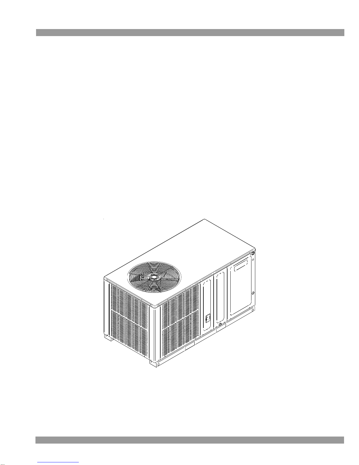
*PC 13 SEER R-410A
Package Air Conditioners
with R-410A
• Refer to Service Manual RS6300011 (Horizontal) for installation, operation,
and troubleshooting information.
• All safety information must be followed as provided in the Service Manual.
• Refer to the appropriate Parts Catalog for part number information.
• Models listed on page 3.
This manual is to be used by qualified, professionally trained HV AC technicians only .
Goodman does not assume any responsibility for property damage or personal injury
due to improper service procedures or services performed by an unqualified person.
Copyright © 2008 - 2013 Goodman Manufacturing Company, L.P.
RT6322006r10
September 2013
Page 2
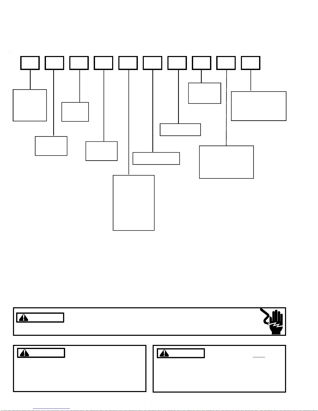
PRODUCT IDENTIFICATION
The model and manufacturing number are used for positive identification of component parts used in manufacturing. Please
use these numbers when requesting service or parts information.
GPC1324H41AA
VOLTAGE:
BRAND:
G: Goodman
Brand
A: Aman a
®
Brand
PRODUCT
TYPE:
Pac kage Unit
®
PRODUCT
FAMILY:
C: Coo l in g
REFRIGERANT:
4: R-410A
PRODUCT
SERIES:
SEER Rating
CONFIGURATION:
H: Ho rizo n tal
NOMINAL
CAPACITY
24: 24,000 BTUH
30: 30,000 BTUH
36: 36,000 BTUH
42: 42,000 BTUH
48: 48,000 BTUH
49: 48,000 BTUH
60: 60,000 BTUH
1: 208-230v
1ph/60Hz
MAJOR REVISION:
A: I nitial Release
B: 2nd Major Rev ision
C: 3rd Maj or Revisi on
D: 4th Major R evisi on
MI NOR REVI SI ON:
A: I nitial Release
B: 2nd Minor Rev ision
C: 3rd Mi nor Revis ion
WARNING
WARNING
WARNING
arising from improper service or service procedures. If
you install or perform service on this unit, you assume
responsibility for any personal injury or property damage
which may result. Many jurisdictions require a license to
install or service heating and air conditioning equipment.
2
Disconnect ALL power before servicing or installing this unit. Multiple power
sources may be present. Failure to do so may cause property damage, personal
injury or death.
Goodman will not be responsible
for any injury or property damage
WARNING
HIGH VOLTAGE!
WARNING
WARNING
the requirements of an "entry level technician" as specified by the Air-Conditioning, Heating, and Refrigeration
Institute (AHRI). Attempting to install or repair this unit
without such background may result in product damage,
personal injury or death.
Installation and repair of this unit
should be performed
dividuals meeting (at a minimum)
ONLY by in-
Page 3

PRODUCT IDENTIFICATION
The model and manufacturing number are used for positive identification of component parts used in manufacturing. Please
use these numbers when requesting service or parts information.
GPC1324H41AA
GPC1330H41AA
GPC1336H41AA
GPC1342H41AA
GPC1348H41BA
GPC1360H41BA
5MM
WARNING
WARNING
5 mm model specific
information begins
on page 28.
The United States Environmental Protection Agency (“EPA”) has issued various regulations regarding the introduction and disposal of refrigerants introduced into this unit. Failure to follow
these regulations may harm the environment and can lead to the imposition of substantial fines.
These regulations may vary by jurisdiction. Should questions arise, contact your local EPA office.
WARNING
WARNING
property damage, personal injury, reduced unit performance and/or hazardous conditions may result from the
use of such non-approved devices.
Do not connect or use any device
that is not design certified by Goodman for use with this unit. Serious
WARNING
WARNING
do not store combustible materials or use gasoline or
other flammable liquids or vapors in the vicinity of this
appliance.
To prevent the risk of property
damage, personal injury, or death,
3
Page 4

PRODUCT DESIGN
GPC Package Cooling Units are designed for outdoor installations only in either residential or light commercial applications.
The connecting ductwork (Supply and Return) can be connected for either horizontal or vertical airflow. In the vertical
application a matching Roof Curb is recommended.
A return air filter must be installed behind the return air grille(s)
or provision must be made for a filter in an accessible location within the return air duct. The minimum filter area should
not be less than those sizes listed in the Specification Section. Under no circumstances should the unit be operated
without return air filters.
A 3/4” PVC pipe is provided for removal of condensate water
from the indoor coil In order to provide proper condensate
flow, a drain trap is supplied and shipped loose inside the
unit for field installation. (Do not reduce the drain line size.)
Refrigerant flow control is achieved by use of restrictor orifices. GPC units use the FasTest Access Fitting System
with a saddle that is either soldered to the suction and liquid
lines or is fastened with a locking nut to the access fitting
box (core) and then screwed into the saddle.
move the core from the saddle until the refrigerant
charge has been removed. Failure to do so could result in property damage or personal injury.
The single phase units use permanent split capacitor (PSC)
design compressors. Starting components are therefore not
required for these units. A low microfarad run capacitor assists the compressor to start and remains in the circuit during operation.
The outdoor fan and indoor blower motors are single phase
capacitor type motors with the exception of the GPC1360H41*
units which have EEM indoor blower motors that are energized by a 24V signal from the thermostat and are constant
torque motors with very low power consumption. The EEM
features an integral control module.
Air for condensing (cooling cycle) is drawn through the outdoor coil by a propeller fan, and is discharged vertically out
the top of the unit. The outdoor coil is designed for .0 static.
No additional restriction (ductwork) shall be applied.
Conditioned air is drawn through the filter(s), field installed,
across the coil and back into the conditioned space by the
indoor blower.
GPC1330-60H41* use Copeland Scroll Compressors.
- Due to their design Scroll Compressors are inherently
more tolerant of liquid refrigerant. NOTE: Even though the
compressor section of a Scroll compressor is more tolerant of liquid refrigerant, continued floodback or flooded
start conditions may wash oil from the bearing surfaces
causing premature bearing failure.
- These Scroll compressors use "POE" or polyolester oil which
is NOT compatible with mineral oil based lubricants like
3GS. "POE" oil must be used if additional oil is required.
- Operating pressures and amp draws may differ from standard reciprocating compressors. This information may be
found in the "Cooling Performance Data" section.
Do not re-
Location and Clearances
NOTE: To ensure proper condensate drainage, unit must be
installed in a level position.
36"
WALL
UNIT
36"
10"
36"
Outside Slab Installation - Horizontal (H)
Minimum clearances are required to avoid air recirculation and
keep the unit operating at peak efficiency.
36"
U
N
I
T
P
L
E
N
U
M
24"
P
L
A
T
F
O
R
M
B
R
U
C
36"
Rooftop Installation - Horizontal (H)
4
Page 5
PRODUCT DESIGN
In installations where the unit is installed above ground level
and not serviceable from the ground (Example: Roof Top installations), the installer must provide service platform for service person with rails or guards in accordance with local codes
or ordinances or in their absence with the latest edition of the
Uniform Mechanical Code Section 305.
NOTE: Unit can also use roof curb.
WARNING
TO PREVENT POSSIBLE PROPERTY DAMAGE, THE
UNIT SHOULD REMAIN IN AN UPRIGHT POSITION
DURING ALL RIGGING AND MOVING OPERATIONS.
TO FACILITATE LIFTING AND MOVING IF A CRANE
IS USED, PLACE THE UNIT IN AN ADEQUATE CABLE
SLING.
Refer to Roof Curb Installation Instructions for proper curb
installation. Curbing must be installed in compliance with
the National Roofing Contractors Association Manual.
5
Page 6

PRODUCT DIMENSIONS *PC13[24-60]H41**
A
BACK EW
(DUCT OPENINGS)
VI
B
Chassis Mode l A B
*PC1324 22 30
Small
*PC1330 22 30
*PC1336 22 30
*PC1342 24 35
Medium
*PC1349 24 35
Large
Dimensions in inches
6
*PC1348 24 38 3/4
*PC1360 24 38 3/4
Page 7

ACCESSORIES
*PC13[24-60]H41**
ACCESSORIES - *PC/*PH****H UNITS
Par t Nu mber De scri p ti o n
OT18-6 0A O utdoor Thermostat Kit w/Lockou t Stat
OT/ EHR18-60 Emergen c y Heat Relay Kit
HKR Electric Heat Kit
PCCP 101-103 Roof Curb
PCP101-103 Downflow Plenum Kit
PCP101-103R8 Downflow Plenum Kit w/ R-8 Insulation
PCE C101-103 Downflow Econ omizer for GPC-(H) A/C - To Be Used With PCP101-103
PCE H101-103 Downflow Econ omizer for GPH-(H) Heat Pump - To Be U sed W i th PCP101-103
PCMD101-103 M anu al Damper - To Be Used With PCP 101- 103
PCMDM 10 1- 103 Motorized Damper - T o Be Used With PCP101-1 03
GP HMD101- 103 Manual Damper for Hor i zontal Applic ations
SQ RP C H101 Squar e to Round Adapter s 16"& 14 "
SQ RP C H102- 103 Squar e to Round Adapter s 18"& 14 "
SQ RP C 101 Squar e to Round Adapter - For Use Wit h P CCP 10 1- 103 Cur b 16" Rounds
SQ RP C 102- 103 Squar e to Round Adapter F or Use With PCC P 101- 103 Cur b 18" Round s
PCFR101- 103 Externa l Horizontal Filt er Rack
PCE F101-103 Elbow & Flashing w/ R-8 Line r
CDK36 Flush Mount Concentric Duct Kit
CDK36515 F lush Mount Concentric Du ct Kit w / F il ter
CDK3653 0 Step Down Concent r ic Duc t K it
CDK36535 Step Down Concen tric Duct Kit w/ Filter
CDK4872 F lush Mount Concentric Duc t Kit
CDK4872515 F lush Mount Concentric Duc t Kit w / F il ter
CDK4872 530 Step Down Concent r ic Duc t K it
CDK4872535 Step Down Concen tric Duct Kit w/ Filter
SP K 30-60 Singl e Point Wiring Kit
7
Page 8

PRODUCT DESIGN
*PC13[24-60]H41**
ELECTRICAL DATA (*Blower Only, Heat Mode)
Circ uit # 1 Circ uit # 2
Mo de l and
Heat Kit Usage
Minimum Circ uit
Ampacity
at 208 / 240V
Maximum Maximum
Overcurrent Overcurrent
Protection (amps) Protection (amps )
at 208 / 240V at 208 / 240V
Minimum Circ uit
Ampacity
at 208 / 240V
*PC1324H41** -- -- -- --
HKR05*,C* 24 / 27 30 / 30 -- -- 4.75 / 16 ,200
HKR08*,C* 33 / 38 40 / 40 -- -- 7.0 / 23,800
HKR10*,C* 45 / 51 60 / 60 -- -- 9.5 / 32,400
*PC1330H41**
2.4 / 2.4 -- -- -- -HKR05*,C* 24 / 27 30 / 30 -- -- 4.75 / 16 ,200
HKR08*,C* 34 / 39 40 / 40 -- -- 7.0 / 23,800
HKR10*,C* 45 / 52 60 / 60 -- -- 9.5 / 32,400
HKR15*,C* 45 / 52 60 / 60 22 / 25 30 / 30 14.25 / 48,600
*PC1336H41** -- -- -- --
HKR05*,C* 24 / 27 30 / 30 -- -- 4.75 / 16 ,200
HKR08*,C* 34 / 39 40 / 40 -- -- 7.0 / 23,800
HKR10*,C* 45 / 52 60 / 60 -- -- 9.5 / 32,400
HKR15*,C* 45 / 52 60 / 60 22 / 25 30 / 30 14.25 / 48,600
*PC1342H41** -- -- -- --
HKR05*,C* 25 / 27 30 / 30 -- -- 4.75 / 16 ,200
HKR08*,C* 34 / 39 40 / 40 -- -- 7.0 / 23,800
HKR10*,C* 46 / 52 60 / 60 -- -- 9.5 / 32,400
HKR15*,C* 46 / 52 60 / 60 22 / 25 30 / 30 14.25 / 48,600
HKR20*,C* 46 / 52 60 / 60 43 / 49 60 / 60 19.5 / 66,500
*PC1348H41** -- -- -- --
HKR05*,C* 25 / 28 30 / 30 -- -- 4.75 / 16 ,200
HKR08*,C* 34 / 40 40 / 40 -- -- 7.0 / 23,800
HKR10*,C* 46 / 53 60 / 60 -- -- 9.5 / 32,400
HKR15*,C* 46 / 52 60 / 60 22 / 25 30 / 30 14.25 / 48,600
HKR20*,C* 46 / 52 60 / 60 43 / 49 60 / 60 19.5 / 66,500
*PC1349H41**
-- -- -- -HKR05*,C* 25 / 28 30 / 30 -- -- 4.75 / 16 ,200
HKR08*,C* 34 / 40 40 / 40 -- -- 7.0 / 23,800
HKR10*,C* 46 / 53 60 / 60 -- -- 9.5 / 32,400
HKR15*,C* 46 / 52 60 / 60 22 / 25 30 / 30 14.25 / 48,600
HKR20*,C* 46 / 52 60 / 60 43 / 49 60 / 60 19.5 / 66,500
*PC1360H41** -- -- -- --
HKR05*,C* 26 / 30 30 / 30 -- -- 4.75 / 16 ,200
HKR08*,C* 36 / 40 40 / 40 -- -- 7.0 / 23,800
HKR10*,C* 48 / 54 60 / 60 -- -- 9.5 / 32,400
HKR15*,C* 48 / 54 60 / 60 22 / 25 30 / 30 14.25 / 48,600
HKR20*,C* 48 / 54 60 / 60 43 / 49 60 / 60 19.5 / 66,500
IMPORTANT NOTE: A separate power supply is required for the HKR heater kit.
All wires and overcurrent protection devices are sized for use with electric heaters only and without
WARNINGWARNING
refrigeration. If heaters are not installed with above wire size, overheating and fire could occur. See
PACKAGE COOLING SPECIFICATIONS section for minimum circuit ampacity and maximum overcurrent
protection during refrigeration cycle.
8
Actual
kW & BT U
at 240V
Page 9

BLOWER PERFORMANCE DAT A
Dry Coil Data
*PC13[24-60]H41**
Mode l Speed Volts
E.S.P (In. of H2O)
0.1 0.2 0.3 0.4 0.5 0.6 0.7 0.8
Low
Med
*PC1324H41**
*PC1330H41**
*PC1336H41**
*PC1342H41**
*PC1349H41**
*PC1360H41** *PC1348H41**
NOTES:
1. Data shown is Dry Coil. Wet Coil Pressure Drop is approximate.
2. 0.1" H2O, for 2 row indoor coil; 0.2” H2O, for 3 row indoor coil; and 0.3” H2O, for 4 row indoor coil.
3. Data shown does not include filter pressure drop, approx. 0.08” H2O.
4. Reduce airflow by 2% for 208V operation.
High
Low
Med
High
Low
Med
High
Low
Med
High
Low
Med
High
T1
T2/T3
T4/T5
230
230
230
230
230
230
230
230
230
230
230
230
230
230
230
230
230
230
CFM 680 640 590 555 505 440 340 -
WA TTS 155 150 145 140 130 120 110 -
CFM 8 95 855 815 755 700 630 545 390
WA TTS 230 220 215 205 195 180 170 145
CFM 1,185 1,130 1,070 1,010 930 850 760 650
WA TTS 350 340 325 310 295 280 265 245
CFM 1,150 1,080 1,025 975 925 845 - -
WA TTS 340 330 315 305 295 280 - -
CFM 1,335 1,275 1,205 1,135 1,075 985 910 845
WA TTS 425 415 400 385 370 350 330 310
CFM 1,435 1,355 1,290 1,210 1,130 1,040 960 885
WA TTS 485 465 455 435 415 400 385 370
CFM 1,180 1,125 1,075 1,020 955 875 655 -
WA TTS 335 325 315 305 295 275 240 -
CFM 1,350 1,280 1,205 1,130 1,050 985 910 845
WA TTS 435 420 405 385 375 350 330 310
CFM 1,450 1,370 1,290 1,205 1,130 1,040 960 885
WA TTS 495 480 465 440 425 400 385 370
CFM 1,425 1,410 1,355 1,310 1,245 1,170 1,080 -
WA TTS 450 445 430 420 405 390 370 -
CFM 1,620 1,595 1,545 1,485 1,425 1,345 1,250 1,160
WA TTS 550 540 525 510 495 475 450 425
CFM 1,945 1,935 1,875 1,800 1,730 1,635 1,535 1,440
WA TTS 765 755 735 715 695 670 640 615
CFM 1,425 1,410 1,355 1,310 1,245 1,170 1,080 -
WA TTS 450 445 430 420 405 390 370 -
CFM 1,720 1,660 1,585 1,520 1,460 1,365 1,270 -
WA TTS 560 555 540 530 520 490 470 -
CFM 2,110 2,060 1,980 1,895 1,795 1,705 1,590 1,500
WA TTS 785 780 765 745 720 705 665 625
CFM 1,507 1,459 1,410 1,362 1,314 1,266 1,218 1,169
WA TTS 168 175 183 191 199 207 214 222
CFM 1,694 1,646 1,598 1,549 1,501 1,453 1,405 1,357
WA TTS 296 303 311 319 327 334 342 350
CFM 1,965 1,917 1,869 1,821 1,773 1,724 1,676 1,628
WA TTS 481 489 496 504 512 520 528 535
9
Page 10
BLOWER PERFORMANCE DAT A
÷ CFM
130 140 150
800
900
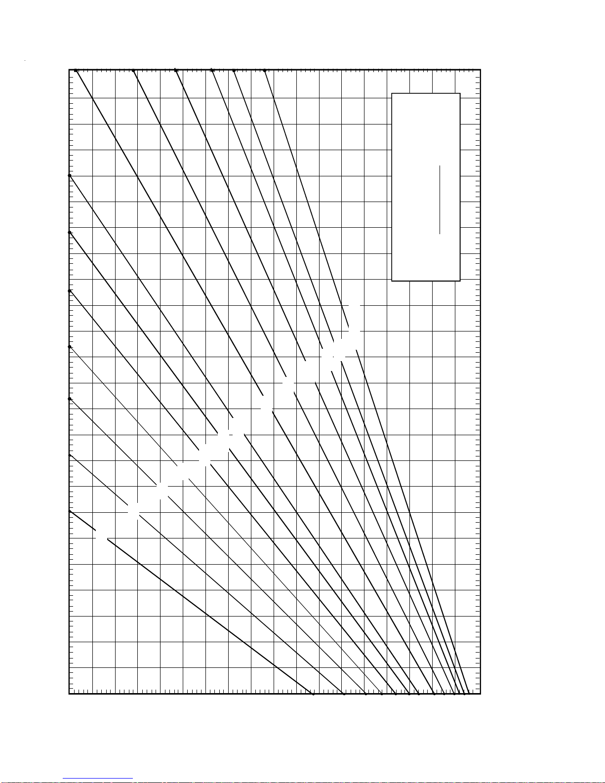
FORMULAS
BTU OUTPUT = CFM x 1.08 x RISE
1.08
BTU OUTPUT
RISE =
100
2400 CFM
2200
2000
1800
1600
1400
1200
1100
1000
OUTPUT BTU/HR x 1000
90
700
80
BTU OUTPUT vs TEMPERATURE RISE CHART
600 CFM
100
10
70
60
50
30 40 50 60 70 80 90 110 120
40
30
20
10
TEMPERATURE RISE
Page 11

PACKAGE COOLING SPECIFICA TIONS
GPC1324H41AA GPC1330H41AA GPC1336H41AA GPC1342H41AA
GPC13[24-42]H41AA
COOLING
CAPACITY
UNIT
ELECTRICAL
SPECIFICATION
COMPRESSOR
CONDENSER
FAN M O TOR
CONDENSER FAN
CONDENSER
COIL
EVAPORATOR
BLOWER
MOTOR
EVAPORATOR
BLOWER
COOLING CAPA CITY, BTUH 24,000 28,600 36,000 41,000
SEER 13.0 13.0 13.0 13.0
VOLTAGE (NAMEPLATE) 208-230/1/60 208-230/1/60 208-230/1/60 208-230/1/60
AMPS (TOTAL) 10.5 13.16 20.06 22.2
MINIMUM CIRCUIT AMPACITY 12.5 15.6 24.2 26.6
MAXIMUM OVERCU R R ENT PR OT ECT ION
TYPE REC IP RECIP SCROLL SCROLL
RAT E D LOA D AMPS 7.9 9.8 16 .7 17.9
L OCKED ROTOR AMPS 41 55 79 11 2
HORSEPOWER 1/6 1/4 1/4 1/4
RPM
FULL LOAD AMPS 1.1 1.5 1.5 1.4
L OCKED ROTOR AMPS 1.7 3.0 3. 0 2.9
BLADE DIAMETER (INCHES) / # OF BLA DES 22 / 3 22 / 3 22 / 4 22 / 4
FACE AREA - SQ. FT. 13.4 13.4 13.4 17.0
NU M B ER OF ROWS 1 1 1 1
FI NS PER INCH 24 24 24 24
HORSEPOWER - NO. OF SPE EDS 1 /4 - 3 1/3 - 3 1/3 - 3 1/2 - 3
FULL LOAD AMPS 1.5 1.86 1.86 2.87
L OCKED ROTOR AMPS 2.2 3.2 3. 2 4.9
MOTOR SPEED TAP - CO OLING M ED IUM LOW L OW LOW
RPM 1075 1075 1075 1075
DIAMETER X WIDTH (IN CHES) 9 x 6 9 x 6 9 x 8 10 x 8
RAT E D SCF M COO LIN G 8 15 1, 080 1, 205 1 , 410
MAX EXTERNAL STATIC PR ESS ("w.c.) 0.5 0.5 0.5 0.5
(1)
20 25 40 40
815
830 830 1075
EVAPORATOR
COIL
GENERAL
INFORMATION
(1)
Maximum Overcurrent Protection Device: MUST use Time Delay Fuse or HACR type Circuit Breaker of the same size as noted.
*
Calculated external filter size based on air velocity of 300 ft/min.
FACE AREA - SQ. FT. 4.6 4.6 5.2 6.2
NU M B ER OF ROWS 3 3 3 4
FI NS PER INCH 14 14 14 14
FILTER SIZE - SQ. FT. * 20 x 20 x 1 20 x 25 x 1 25 x 25 x 1 (2) 20 x 20 x 1
DRAIN SIZE ( IN CHES) 3/4" 3/ 4" 3/4" 3/4"
EXPANSIO N DEVICE ORIFIC E (0 .05 9) ORRIFIC E (0.060) ORIFICE (0.065 ) ORIFICE (0.072 )
REFRIGERANT CHARGE R-410A (Oz.) 80 80 85 105
POWER SUPPLY CONDUIT KNOCKOUT SIZE (IN.) 3/4 , 1, 1-1/ 4 3/4, 1, 1-1/4 3/4, 1, 1-1/4 3/4, 1, 1 -1/4
LOW V OL TAGE CO ND U IT KNO C K O U T SIZ E (IN .) 1 / 2 1/ 2 1/2 1/2
SHIPPING WEIGHT LBS. 310 310 370 370
OPERATING WEIGHT LBS. 300 300 360 360
Wire size should be determined in accordance with National Electrical Codes. Extensive wire runs will require larger wire sizes.
Unit specifications are subject to change without notice. ALWAYS refer to the units serial plate for the most up-to-date general and electrical information.
IMPORTANT: While this data is presented as a guide, it is important to electrically connect the unit and properly size wires and fuses/circuit breakers
in accordance with the National Electrical Code and/or all local codes. Data shown is w/o electric heaters.
11
Page 12

PACKAGE COOLING SPECIFICA TIONS
GPC13[48-60]H41BA
GPC1348H41BA GPC1360H41BA
COOLING
CAPACITY
UNIT
ELECTRICAL
SPECIFICATION
COMPRESSOR
CONDENSER
FAN MOT O R
CONDENSER FAN
CONDENSER
COIL
EVAPORATOR
BLOWER
MOTOR
COOLING CAPACI TY, BTUH 45,500 57,500
SEER 13.0 13.0
VOLTAGE (NAMEPLATE) 208-230/1/60 208-230/1/60
AM PS (TOT AL) 24 . 17 33.6
MINIMUM CIRCUIT AMPACI TY 29.2 4 0.2
MAXIMUM OVERCURRENT PROTECTION
TYPE SC ROLL SCROLL
RA TE D LOA D AMPS 19 .9 26.4
L O C KED RO TOR AMP S 10 9 13 4
HORSEPOWER 1/4 1/4
RPM 1075 1075
FU LL LOAD AMPS 1.4 1.4
L O C KED RO TOR AMP S 2 . 9 2.9
BLAD E DI AMETER (INCHES) /# OF BLADES 2 2 / 4 22 / 4
FACE AREA - SQ. FT. 19.1 19.1
NUMBER OF ROW S 1 2
FINS PER INCH 21 16
HORSEPOWER - NO. OF SPEEDS 1/2 - 3 3/4 - 3
FULL LOAD AMPS 2.87 5.8
L O C KED RO TOR AMP S 4 . 9 NA
(1)
45 60
MOTOR SP EED TAP - COOLING MEDIUM T2
RPM 1075 1075
EVAPORATOR
BLOWER
EVAPORATOR
COIL
GENERAL
INFOR MATION
(1)
Maximum Overcurrent Protection Device: MUST use Time Delay Fuse or HACR type Circuit Breaker of the same size as noted.
*
Calculated external filter size based on air velocity of 300 ft/min.
DIAMETER X WIDTH (INCHES) 10 x 8 11 x 8
R A TED SC F M COOLING 1,585 1, 850
MAX EXTERNAL STATIC PRESS ("w.c.) 0.5 0.5
FACE AREA - SQ. FT. 6.2 7.0
NUMBER OF ROW S 4 4
FINS PER INCH 14 14
FILTER SIZE - SQ. FT. * (2) 20 x 20 x 1 (2) 20 x 25 x 1
DRAIN SIZE (INCHES) 3/4" 3/4"
EXPANSIO N DEVI CE OR RI FI CE (0.07 6) ORI FIC E (0. 088)
REFRIGERANT CHARGE R-410A (O z.) 110 160
POWER SUPPLY CONDUIT KNOCKOUT SI Z E (IN.) 3/4, 1, 1-1/4 3/4, 1, 1-1/4
LOW VOLTAGE CONDUIT KNOCKOUT SIZE (IN. ) 1/2 1/2
SHIPPING WE I GHT LBS. 400 400
O PE RA TI NG WE IGHT LBS. 39 0 390
Wire size should be determined in accordance with National Electrical Codes. Extensive wire runs will require larger wire sizes.
Unit specifications are subject to change without notice. ALWAYS refer to the units serial plate for the most up-to-date general and electrical information.
IMPORTANT: While this data is presented as a guide, it is important to electrically connect the unit and properly size wires and fuses/circuit breakers
in accordance with the National Electrical Code and/or all local codes. Data shown is w/o electric heaters.
12
Page 13
COOLING PERFORMANCE DA TA GPC1324H41AA
COOLING OPERATION
EXPANDED PERFORMANCE DATA
15 11 20 19 15 10 18 17 14 10
9.2 9.5 9.2 9.4 9.7 10.0 9.7 9.9 10.2 10.6
371 386 367 39 5 417 435 405 436 461 480
24.8 26.6 21.1 21.8 23.6 25.3 19.6 20.2 21.8 23. 4
0.66 0.43 1.00 0.91 0.69 0.44 1.00 0.91 0.69 0.45
19
22.9
0.87
Outdoor Ambient Temperature
Entering Indoor Wet Bulb Temperature
152 161 137 14 6 159 169 141 151 164 175
2.17 2.24 2.14 2.19 2.26 2.33 2.21 2.26 2.34 2.41
8.9
351
139
2.10
16 11 21 19 16 11 19 18 15 10
9.1 9.4 9.1 9.3 9.6 9.9 9.6 9.8 10.1 10.5
367 383 363 39 1 413 430 401 432 456 476
24.1 25.8 20.5 21.1 22.9 24.5 19.0 19.6 21.2 22. 7
0.63 0.41 0.97 0.86 0.65 0.42 0.97 0.87 0.66 0.42
19
22.2
0.83
150 160 135 14 4 157 168 140 149 163 173
2.15 2.22 2.12 2.17 2.24 2.31 2.20 2.24 2.32 2.39
8.8
347
137
2.08
16 11 22 20 16 11 20 19 15 10
9.0 9.3 9.0 9.2 9.5 9.8 9.5 9.7 10.0 10.3
360 375 356 38 3 404 422 393 423 447 466
22.9 24.5 19.5 20.1 21.7 23.3 18.1 18.6 20.1 21. 6
0.60 0.39 0.93 0.83 0.63 0.40 0.93 0.84 0.63 0.41
20
21.1
0.80
147 157 133 14 1 154 164 137 146 159 170
2.12 2.18 2.09 2.14 2.20 2.28 2.16 2.21 2.28 2.35
8.7
340
135
2.05
65 75 85 95 105 115
S/T 0.78 0.65 0.45 - 0.81 0.68 0.47 - 0.83 0.70 0.48 - 0.86 0.72 0.50 - 0.89 0.74 0.52 - 0.90 0.75 0.52 -
MBh 23.5 24.4 26.7 - 23.0 23.8 26.1 - 22.4 23.2 25.5 - 21.9 22.7 24.8 - 20.8 21.5 23.6 - 19.3 20.0 21.9 -
Design Subcooling, 12±3 °F @ the liquid access fitting connection AHRI 95 test conditions. Design Superheat 8±3 °F @ the compressor suction access fitting connectio n.
MODEL: GPC1324 H41A*
IDB*Airflow 59636771596367715963677159 63 67 715963677159636771
Delta T171511 - 171511 - 181512 - 18 15 12 - 171511 - 161411 -
AMPS 7.1 7.3 7.5 - 7.6 7.8 8.0 - 8.2 8.3 8.6 - 8.7 8.8 9.1 - 9.1 9.3 9.6 - 9.6 9.8 10.1 -
HI PR 222 239 252 - 249 268 283 - 283 305 322 - 323 347 367 - 363 391 413 - 401 432 456 -
LO PR 112 119 130 - 118 126 137 - 123 131 143 - 129 137 150 - 135 144 157 - 140 149 163 -
980 KW 1.71 1.74 1.79 - 1.83 1.87 1.93 - 1.94 1.98 2 .05 - 2.04 2.08 2.15 - 2.12 2.17 2.24 - 2.20 2.24 2.32 -
S/T 0.75 0.62 0.43 - 0.77 0.65 0.45 - 0.79 0.66 0.46 - 0.82 0.68 0.47 - 0.85 0.71 0.49 - 0.86 0.72 0.50 -
MBh 22.8 23.7 25.9 - 22.3 23.1 25.3 - 21.8 22.6 24.7 - 21.2 22.0 24.1 - 20.2 20.9 22.9 - 18.7 19.4 21.2 -
Delta T181612 - 181612 - 181612 - 18 16 12 - 181612 - 171511 -
AMPS 7.1 7.2 7.4 - 7.6 7.7 7.9 - 8.1 8.3 8.5 - 8.6 8.8 9.0 - 9.1 9.3 9.5 - 9.5 9.8 10.0 -
HI PR 220 237 250 - 247 265 280 - 281 302 319 - 320 344 363 - 360 387 409 - 397 427 451 -
70 875 KW 1.69 1.73 1.78 - 1.8 2 1.85 1.91 - 1.93 1.97 2.03 - 2.02 2.07 2.13 - 2.11 2.15 2.22 - 2.18 2.23 2.30 -
S/T 0.72 0.60 0.41 - 0.74 0.62 0.43 - 0.76 0.64 0.44 - 0.79 0.66 0.45 - 0.81 0.68 0.47 - 0.82 0.69 0.48 -
MBh 21.7 22.5 24.6 - 21.2 22.0 24.1 - 20.7 21.4 23.5 - 20.2 20.9 22.9 - 19.2 19.9 21.8 - 17.8 18.4 20.2 -
LO PR 111 118 129 - 117 125 136 - 122 130 141 - 128 136 149 - 134 143 156 - 139 148 161 -
Delta T191612 - 191612 - 191612 - 19 16 12 - 191612 - 171511 -
770 KW 1.67 1.70 1.75 - 1.79 1.83 1.88 - 1.90 1.94 2 .00 - 1.99 2.03 2.10 - 2.07 2.12 2.19 - 2.14 2.19 2.26 -
AMPS 7.0 7.1 7.3 - 7.4 7.6 7.8 - 8.0 8.2 8.4 - 8.5 8.6 8.9 - 8.9 9.1 9.4 - 9.4 9.6 9.9 -
HI PR 215 232 245 - 242 260 275 - 275 296 312 - 313 337 356 - 352 379 400 - 389 419 442 -
LO PR 109 116 126 - 115 122 133 - 119 127 139 - 125 133 146 - 131 140 153 - 136 145 158 -
MBh 23.924.626.728.623.424.126.027.922.823.525.427.322.2
S/T 0.89 0.80 0.60 0.39 0.92 0.83 0.62 0.40 0.95 0.85 0.64 0 .41 0.98
Delta T20181510201915112019151120
980 KW 1.72 1.75 1.81 1.86 1.85 1.88 1.94 2.00 1.96 2.00 2.06 2.13 2.06
AMPS 7.27.37.57.87.77.88.18.38.28.48.78.98.7
HI PR 224 241 255 266 252 271 286 298 286 308 325 33 9 326
S/T 0.85 0.76 0.57 0.37 0.88 0.79 0.60 0.38 0.90 0.81 0.61 0 .39 0.93
MBh 23.223.925.927.822.723.425.327.122.122.824.726.521.6
LO PR 113 120 131 140 120 127 139 148 124 132 144 15 4 131
Delta T21191611211916112119161121
75 875 KW 1.71 1.74 1.79 1.85 1.83 1.87 1.93 1.99 1.94 1.98 2.05 2.11 2.04
AMPS 7.17.37.57.77.67.88.08.28.28.38.68.98.7
HI PR 222 239 252 263 249 268 283 295 283 305 322 33 6 323
S/T 0.81 0.73 0.55 0.35 0.84 0.75 0.57 0.37 0.86 0.77 0.59 0 .38 0.89
MBh 22.122.724.626.421.522.224.025.821.021.723.425.220.5
LO PR 112 119 130 139 118 126 137 146 123 131 143 15 2 129
Delta T21201611222016112220161122
770 KW 1.68 1.71 1.77 1.82 1.80 1.84 1.90 1.96 1.91 1.95 2.01 2.08 2.01
AMPS 7.07.27.47.67.57.77.98.18.08.28.58.78.5
HI PR 218 234 247 258 244 263 278 289 278 299 316 32 9 316
LO PR 110 117 128 136 116 123 135 143 121 128 140 14 9 127
* IDB: Entering Indoor Dry Bulb Temperature NOTE: Shaded area is ACCA (TVA) conditions
High and low pressures are measured at the liquid and suc tio n access fittings.
13
Page 14
COOLING PERFORMANCE DA TA GPC1324H41AA
COOLING OPERATION
16 22 22 19 15 20 21 18 14
9.5 9.2 9.4 9.7 10.0 9.7 9.9 10.2 10.6
386 367 395 417 435 405 436 461 480
2.24 2.14 2.19 2.26 2.33 2.21 2.26 2.34 2.41
25.7 20.9 21.3 22.8 24.4 19.3 19.8 21.1 22.6
0.58 1.00 0.99 0.81 0.61 1.00 1.00 0.82 0.61
20
24.0
0.78
161 137 146 159 169 141 151 164 175
9.2
371
152
2.17
EXPANDED PERFORMANCE DATA
Outdoor Ambient Temperature
Entering Indoor Wet Bulb Temperature
65 75 85 95 105 115
S/T 1.00 0.92 0.75 0.56 1.00 0.95 0.77 0.58 1.00 1.00 0.79 0.59 1.00 1.00 0 .82 0.61 1.00 1.00 0.85 0.63 1.00 1.00 0.86 0.64
MBh 24.324.926.628.423.824.326.027.723.223.725.327.122.6 23.1 24.7 26.421.522.023.525.119.920.421.823.3
Design Subcooling, 12±3 °F @ the liquid access fitting connection AHRI 95 test conditions. Design Superhe at 8±3 °F @ the compressor suction acc ess fitting connectio n.
Delta T23211915222219152222191521 22 19 152021191519191714
AMPS 7.2 7.4 7.6 7.8 7.7 7.9 8.1 8.4 8.3 8.5 8.7 9.0 8.8 9.0 9.3 9.6 9.3 9.5 9.8 10 .1 9.8 10.0 10.3 10.7
HI PR 227 244 257 269 254 274 289 301 289 311 329 34 3 329 354 374 390 371 399 421 43 9 409 441 465 485
S/T 0.93 0.87 0.71 0.53 0.97 0.91 0.74 0.55 0.99 0.93 0.76 0.56 1.00 0.96
MBh 23.624.125.827.623.123.625.226.922.523.024.626.322.0 22.5
LO PR 114 122 133 141 121 128 140 149 126 134 146 15 5 132 140 153 163 138 147 160 171 143 152 16 6 177
Delta T23221915232220162322201623 23
AMPS 7.27.37.57.87.77.88.18.38.28.48.78.98.7 8.9
HI PR 224 241 255 266 252 271 286 298 286 308 325 33 9 326 351
S/T 0.89 0.84 0.68 0.51 0.92 0.87 0.71 0.53 0.95 0.89 0.72 0.54 0.98 0.92 0 .75 0.56 1.02 0.95 0.78 0.58 1.02 0.96 0.78 0.58
MBh 22.522.924.526.221.922.423.925.621.421.923.425.020.9 21.3 22.8 24.419.820.321.723.218.418.820.121.4
LO PR 113 120 131 140 120 127 139 148 124 132 144 15 4 131 139
Delta T24232016242320162423201624 23 20 162423201622221915
AMPS 7.1 7.2 7.4 7.6 7.6 7.7 7.9 8.2 8.1 8.3 8.5 8.8 8.6 8.8 9.0 9.3 9.1 9.3 9.5 9.9 9.5 9.8 10.0 10.4
HI PR 220 237 250 261 247 265 280 292 281 302 319 33 3 320 344 363 379 360 387 409 42 6 397 427 451 471
LO PR 111 118 129 137 117 125 136 145 122 130 141 15 1 128 136 149 158 134 143 156 166 139 148 16 1 172
MBh 24.825.226.428.224.224.725.827.623.624.125.226.923.0 23.5 24.6 26.221.922.323.424.920.320.721.623.1
S/T 1.00 0.99 0.89 0.72 1.00 1.00 0.92 0.75 1.00 1.00 0.95 0.77 1.00 1.00 0 .98 0.79 1.00 1.00 1.00 0.82 1.00 1.00 1.00 0.83
Delta T23232219232322192223221922 22 23 202121221919192018
AMPS 7.3 7.4 7.6 7.9 7.8 8.0 8.2 8.4 8.4 8.5 8.8 9.1 8.9 9.1 9.3 9.6 9.4 9.6 9.9 10 .2 9.9 10.1 10.4 10.7
HI PR 229 246 260 271 257 276 292 304 292 314 332 34 6 333 358 378 394 374 403 425 44 4 413 445 470 490
S/T 0.98 0.94 0.85 0.69 1.00 0.98 0.88 0.71 1.00 1.00 0.90 0.73 1.00 1.00 0 .93 0.76 1.00 1.00 0.97 0.79 1.00 1.00 0.98 0.79
MBh 24.024.525.727.423.523.925.126.822.923.424.526.122.4 22.8 23.9 25.521.221.722.724.219.720.121.022.4
LO PR 115 123 134 143 122 130 142 151 127 135 147 15 7 133 142 155 165 140 148 162 173 144 154 16 8 179
Delta T25242320252523202425232024 24 23 202223232021212219
AMPS 7.2 7.4 7.6 7.8 7.7 7.9 8.1 8.4 8.3 8.5 8.7 9.0 8.8 9.0 9.3 9.6 9.3 9.5 9.8 10 .1 9.8 10.0 10.3 10.7
HI PR 227 244 257 269 254 274 289 301 289 311 329 34 3 329 354 374 390 371 399 421 43 9 409 441 465 485
S/T 0.94 0.90 0.81 0.66 0.97 0.94 0.84 0.68 0.99 0.96 0.87 0.70 1.00 0.99 0 .89 0.72 1.00 1.00 0.93 0.75 1.00 1.00 0.94 0.76
MBh 22.823.324.426.022.322.723.825.421.822.223.324.821.2 21.7 22.7 24.220.220.621.623.018.719.120.021.3
LO PR 114 122 133 141 121 128 140 149 126 134 146 15 5 132 140 153 163 138 147 160 171 143 152 16 6 177
Delta T26252421262524212625242125 26 24 212425242122232219
AMPS 7.1 7.3 7.5 7.7 7.6 7.8 8.0 8.2 8.2 8.3 8.6 8.9 8.7 8.8 9.1 9.4 9.1 9.3 9.6 9.9 9.6 9.8 10.1 10.5
HI PR 222 239 252 263 249 268 283 295 283 305 322 33 6 323 347 367 383 363 391 413 43 0 401 432 456 475
LO PR 112 119 130 139 118 126 137 146 123 131 143 15 2 129 137 150 160 135 144 157 167 140 149 16 3 173
980 KW 1.73 1.77 1.82 1.88 1.86 1.90 1.96 2.02 1.97 2.02 2.08 2 .15 2.07 2.12 2 .19 2.26 2.16 2.21 2.28 2.35 2.23 2.28 2.36 2.43
MODEL: GPC1324H41A*
IDB*Airflow 59636771596367715963677159 63 67 715963677159636771
80 875 KW 1.72 1.75 1.81 1.86 1.85 1.88 1.94 2.00 1.96 2.00 2.06 2 .13 2.06 2.10
14
770 KW 1.69 1.73 1.78 1.83 1.82 1.85 1.91 1.97 1.93 1.97 2.03 2 .09 2.02 2.07 2 .13 2.20 2.11 2.15 2.22 2.29 2.18 2.23 2.30 2.37
980 KW 1.74 1.78 1.84 1.89 1.87 1.91 1.97 2.04 1.99 2.03 2.10 2 .16 2.09 2.14 2 .20 2.28 2.18 2.22 2.30 2.37 2.25 2.30 2.38 2.45
85 875 KW 1.73 1.77 1.82 1.88 1.86 1.90 1.96 2.02 1.97 2.02 2.08 2 .15 2.07 2.12 2 .19 2.26 2.16 2.21 2.28 2.35 2.23 2.28 2.36 2.43
770 KW 1.71 1.74 1.79 1.85 1.83 1.87 1.93 1.99 1.94 1.98 2.05 2 .11 2.04 2.08 2 .15 2.22 2.12 2.17 2.24 2.31 2.20 2.24 2.32 2.39
High and low pressures are measured at the liquid and suction access fi ttings. AMPS: Uni t amps (com p.+ evaporator + condenser fan motors)
* NOTE: Shaded area is AHRI R atin g Conditions IDB: Entering Indoor Dry Bulb Temper ature KW = To tal system power
Page 15
COOLING PERFORMANCE DA TA GPC1330H41AA
COOLING OPERATION
E XP ANDED PERF O RMA NCE DA T A
15 11 20 19 15 11 18 17 14 10
386 403 382 412 435 453 423 455 480 501
29.8 31.9 25.4 26.1 28.3 30.3 23.5 24.2 26.2 28.1
0.67 0.43 1.00 0.91 0.69 0.45 1.00 0.92 0.70 0.45
19
27.5
0.88
Outdoor Ambient Temperature
Entering Indoor Wet Bulb Temperature
151 160 136 145 158 168 141 150 163 174
2.62 2.70 2.58 2.64 2.72 2.81 2.67 2.73 2.81 2.91
11.2 11.6 11.3 11.5 11.9 12.2 11.9 12.1 12.5 12.9
366
138
2.54
10.9
16 11 21 19 16 11 20 18 15 10
383 399 379 408 430 449 418 450 475 496
28.9 31.0 24.6 25.4 27.4 29.5 22.8 23.5 25.4 27.3
0.64 0.41 0.98 0.87 0.66 0.42 0.98 0.88 0.67 0.43
20
26.7
0.84
149 159 135 143 156 166 139 148 162 172
2.60 2.68 2.56 2.62 2.70 2.79 2.65 2.71 2.79 2.88
11.2 11.5 11.2 11.4 11.8 12.2 11.8 12.0 12.4 12.8
362
137
2.52
10.8
16 11 21 20 16 11 20 18 15 10
371 387 367 395 417 435 406 437 461 481
26.7 28.6 22.7 23.4 25.3 27.2 21.1 21.7 23.5 25.2
0.61 0.39 0.94 0.84 0.64 0.41 0.95 0.85 0.64 0.41
20
24.6
0.81
145 154 130 139 152 161 135 144 157 167
2.53 2.61 2.50 2.56 2.64 2.72 2.59 2.64 2.72 2.81
10.9 11.2 10.9 11.2 11.5 11.9 11.5 11.7 12.1 12.5
351
132
2.46
10.6
65 75 85 95 105 115
S/T 0.79 0.66 0.46 - 0.82 0.68 0.47 - 0.84 0.70 0.49 - 0.87 0.72 0.50 - 0.90 0.75 0.52 - 0.91 0.76 0.53 -
MBh 28.2 29.3 32.0 - 27.6 28.6 31.3 - 26.9 27.9 30.6 - 26.3 27.2 29.8 - 24.9 25.8 28.3 - 23.1 23.9 26.2 -
Design Subcooling, 12± 3 °F @ the liqui d access fitting connection AHRI 95 test conditions. Design Superheat 8±3 °F @ the compressor suction access fitting conn e ction.
MODEL: GPC1330H41A*
IDB*Airflow 59636771596367715963677159 63 67 715963677159636771
AMPS 8.8 9.0 9.2 - 9.4 9.6 9.8 - 10.0 10.2 10.5 - 10.6 10.8 11.1 - 11.2 11.4 11.8 - 11.8 12.0 12.4 -
HI PR 232 249 2 63 - 260 280 2 95 - 296 318 336 - 337 362 382 - 379 407 430 - 418 450 475 -
Delta T 17 15 11 - 18 15 12 - 18 15 12 - 18 15 12 - 17 15 11 - 16 14 11 -
LO PR 111 118 129 - 118 125 137 - 122 130 142 - 128 137 149 - 135 143 156 - 139 148 162 -
1180 KW 2.07 2.11 2.17 - 2.22 2.26 2.33 - 2.35 2.40 2.47 - 2.46 2.52 2.59 - 2.56 2.62 2.70 - 2.65 2.70 2.79 -
S/T 0.75 0.63 0.44 - 0.78 0.65 0.45 - 0.80 0.67 0.46 - 0.83 0.69 0.48 - 0.86 0.72 0.50 - 0.87 0.72 0.50 -
MBh 27.4 28.4 31.1 - 26.8 27.7 30.4 - 26.1 27.1 29.7 - 25.5 26.4 28.9 - 24.2 25.1 27.5 - 22.4 23.2 25.5 -
AMPS 8.7 8.9 9.1 - 9.3 9.5 9.8 - 10.0 10.2 10.5 - 10.5 10.8 11.1 - 11.1 11.3 11.7 - 11.7 11.9 12.3 -
HI PR 229 247 2 61 - 257 277 2 92 - 293 315 332 - 333 359 379 - 375 403 426 - 414 446 471 -
Delta T 18 16 12 - 18 16 12 - 18 16 12 - 18 16 12 - 18 16 12 - 17 15 11 -
70 1050 KW 2.05 2.09 2.16 - 2.20 2.25 2.31 - 2.33 2.38 2.45 - 2.45 2.50 2.57 - 2.54 2.60 2.68 - 2.63 2.68 2.77 -
S/T 0.73 0.61 0.42 - 0.75 0.63 0.44 - 0.77 0.65 0.45 - 0.80 0.67 0.46 - 0.83 0.69 0.48 - 0.83 0.70 0.48 -
MBh 25.3 26.2 28.7 - 24.7 25.6 28.1 - 24.1 25.0 27.4 - 23.5 24.4 26.7 - 22.3 23.2 25.4 - 20.7 21.5 23.5 -
LO PR 110 117 128 - 116 124 135 - 121 129 141 - 127 135 148 - 133 142 155 - 138 147 160 -
AMPS 8.5 8.7 8.9 - 9.1 9.3 9.5 - 9.7 9.9 10.2 - 10.3 10.5 10.8 - 10.9 11.1 11.4 - 11.4 11.6 12.0 -
HI PR 222 239 2 53 - 250 269 2 84 - 284 305 322 - 323 348 367 - 364 391 413 - 402 432 457 -
Delta T 18 16 12 - 19 16 12 - 19 16 12 - 19 16 12 - 18 16 12 - 17 15 11 -
LO PR 107 114 124 - 113 120 131 - 117 125 136 - 123 131 143 - 129 137 150 - 134 142 155 -
920 KW 2.01 2.05 2.11 - 2.15 2.19 2.26 - 2.28 2.32 2.39 - 2.39 2.44 2.51 - 2.48 2.53 2.61 - 2.56 2.62 2.70 -
S/T 0.900.800.610.390.930.830.630.410.950.850.650.420.99
MBh 28.7 29.5 32.0 34.3 28.0 28.9 31.2 33.5 27.4 28.2 30.5 32.7 26.7
Delta T20191510201915112019151120
1180 KW 2.08 2.13 2.19 2.25 2.23 2.28 2.35 2.42 2.37 2.42 2.49 2.57 2.48
AMPS 8.9 9.0 9.3 9.6 9.4 9.6 9.9 10.2 10.1 10.3 10.6 11.0 10.7
HI PR 234 252 2 66 277 262 282 298 311 299 321 339 354 340
S/T 0.860.770.580.370.890.790.600.390.910.810.620.400.94
MBh 27.9 28.7 31.1 33.3 27.2 28.0 30.3 32.6 26.6 27.4 29.6 31.8 25.9
LO PR 112 120 131 139 119 126 138 147 123 131 143 153 130
Delta T21191611211916112120161121
75 1050 KW 2.07 2.11 2.17 2.24 2.22 2.26 2.33 2.40 2.35 2.40 2.47 2.55 2.47
AMPS 8.8 9.0 9.2 9.5 9.4 9.6 9.8 10.1 10.0 10.3 10.5 10.9 10.6
HI PR 232 249 2 63 275 260 280 295 308 296 318 336 350 337
S/T 0.830.740.560.360.860.770.580.370.880.790.590.380.91
MBh 25.7 26.5 28.7 30.8 25.1 25.9 28.0 30.0 24.5 25.2 27.3 29.3 23.9
LO PR 111 118 129 138 118 125 137 145 122 130 142 151 128
Delta T21201611212016112220161122
920 KW 2.022.062.122.192.172.212.282.352.292.342.412.492.41
AMPS 8.6 8.8 9.0 9.3 9.2 9.3 9.6 9.9 9.8 10.0 10.3 10.6 10.4
HI PR 225 242 2 55 266 252 271 286 299 287 309 326 340 327
LO PR 108 115 125 134 114 121 132 141 119 126 138 147 125
* IDB: Entering Indoor Dry Bulb Temperature NOTE: Shaded area is ACCA (TVA) conditions
High and low pressures ar e mea sured at the liquid and sucti on acce ss fittings.
15
Page 16

COOLING PERFORMANCE DA TA GPC1330H41AA
COOLING OPERATION
16 22 22 20 16 20 21 18 15
403 383 412 435 453 423 455 480 501
160 136 145 158 168 141 150 163 174
2.70 2.58 2.64 2.72 2.81 2.67 2.73 2.81 2.91
30.8 25.1 25.6 27.4 29.2 23.2 23.7 25.3 27.1
28.8
11.6 11.3 11.5 11.9 12.3 11.9 12.1 12.5 12.9
0.59 1.00 1.00 0.82 0.61 1.00 1.00 0.82 0.62
20
386
151
2.62
11.2
0.79
E XP ANDED PERF O RMA NCE DA T A
Design Subcooling, 12± 3 °F @ the liqui d access fitting connection AHRI 95 test conditions. Design Superheat 8±3 °F @ the compressor suction access fitting conn e ction.
Outdoor Ambient Temperature
NOTE: Shaded area reflects ARI rating conditions
S/T 1.00 1.00 0.90 0.73 1.00 1.00 0.93 0.76 1.00 1.00 0.96 0.78 1.00 1.00 0.99 0.80 1.00 1.00 1.00 0.83 1.00 1.00 1.00 0.84
AMPS 8.7 8.8 9.1 9.3 9.2 9.4 9.7 10.0 9.9 10.1 10.4 10.7 10.5 10.7 11.0 11.3 11.0 11.3 11.6 12.0 11.6 11.8 12.2 12.6
HI PR 227 244 2 58 269 255 274 289 302 290 312 329 343 330 35 5 375 391 371 399 422 440 410 441 466 486
MBh 29.7 30.3 31.7 33.9 29.0 29.6 31.0 33.1 28.3 28.9 30.3 32.3 27.6 28.2 29.5 31.5 26.3 26.8 28.0 29.9 24.3 24.8 26.0 27.7
LO PR 109 116 127 135 115 123 134 143 120 127 139 148 126 134 146 156 132 140 153 163 136 145 158 169
Delta T23242219232323192223232022 22 23 202021221919192018
AMPS 9.0 9.2 9.4 9.7 9.6 9.8 10.1 10.4 10.3 10.5 10.8 11.1 10.9 11.1 11.4 11.8 11.5 11.7 12.1 12.4 12.1 12.3 12.7 13.1
HI PR 239 257 2 71 283 268 288 304 317 305 328 346 361 347 37 3 394 411 390 420 443 463 431 464 490 511
S/T 0.99 0.95 0.86 0.70 1.00 0.99 0.89 0.72 1.00 1.00 0.91 0.74 1.00 1.00 0.94 0.76 1.00 1.00 0.98 0.79 1.00 1.00 0.99 0.80
MBh 28.9 29.4 30.8 32.9 28.2 28.7 30.1 32.1 27.5 28.0 29.4 31.3 26.8 27.4 28.7 30.6 25.5 26.0 27.2 29.0 23.6 24.1 25.2 26.9
LO PR 115 122 133 142 121 129 141 150 126 134 146 156 132 141 154 164 139 147 161 171 143 153 167 177
Delta T25242320252523202425232024 24 24 202223232021212219
AMPS 8.9 9.1 9.3 9.6 9.5 9.7 10.0 10.3 10.2 10.4 10.7 11.0 10.8 11.0 11.3 11.7 11.4 11.6 12.0 12.3 12.0 12.2 12.6 13.0
HI PR 236 254 2 69 280 265 285 301 314 302 324 343 357 343 37 0 390 407 386 416 439 458 427 459 485 506
S/T 0.95 0.92 0.83 0.67 0.98 0.95 0.86 0.70 1.00 0.97 0.88 0.71 1.00 1.00 0.91 0.74 1.00 1.00 0.94 0.76 1.00 1.00 0.95 0.77
MBh 26.6 27.1 28.4 30.3 26.0 26.5 27.8 29.6 25.4 25.9 27.1 28.9 24.8 25.3 26.4 28.2 23.5 24.0 25.1 26.8 21.8 22.2 23.3 24.8
LO PR 114 121 132 140 120 128 139 148 125 133 145 154 131 139 152 162 137 146 159 170 142 151 165 176
Delta T25252420262524212525242125 25 24 212424242022222219
AMPS 8.7 8.9 9.1 9.4 9.3 9.5 9.7 10.1 10.0 10.2 10.5 10.8 10.5 10.8 11.1 11.4 11.1 11.3 11.7 12.0 11.7 11.9 12.3 12.7
HI PR 229 247 2 60 272 257 277 292 305 292 315 332 347 333 35 8 379 395 375 403 426 444 414 446 471 491
LO PR 110 117 128 136 116 124 135 144 121 129 140 150 127 135 148 157 133 142 155 165 138 147 160 170
65 75 85 95 105 115
Entering Indoor Wet Bulb Temperature
S/T 1.00 0.92 0.75 0.56 1.00 0.96 0.78 0.58 1.00 1.00 0.80 0.60 1.00 1.00 0.83 0.62 1.00 1.00 0.86 0.64 1.00 1.00 0.86 0.65
MBh 29.2 29.8 31.9 34.1 28.5 29.2 31.1 33.3 27.9 28.5 30.4 32.5 27.2 27.8 29.7 31.7 25.8 26.4 28.2 30.1 23.9 24.4 26.1 27.9
Delta T23211915222219152222191521 22 19 152021191519191814
AMPS 8.9 9.1 9.3 9.6 9.5 9.7 10.0 10.3 10.2 10.4 10.7 11.0 10.8 11.0 11.3 11.7 11.4 11.6 12.0 12.3 12.0 12.2 12.6 13.0
HI PR 236 254 2 69 280 265 285 301 314 302 324 343 357 343 37 0 390 407 386 416 439 458 427 459 485 506
S/T 0.940.880.720.540.970.910.740.561.000.940.760.571.00 0.97
MBh 28.4 29.0 31.0 33.1 27.7 28.3 30.2 32.3 27.0 27.6 29.5 31.6 26.4 27.0
LO PR 114 121 132 140 120 128 139 148 125 133 145 154 131 139 152 162 137 146 159 170 142 151 165 176
Delta T23221916242320162423201623 23
AMPS 8.9 9.0 9.3 9.6 9.4 9.6 9.9 10.2 10.1 10.3 10.6 11.0 10.7 10.9
HI PR 234 252 2 66 277 263 282 298 311 299 321 339 354 340 36 6
S/T 0.91 0.85 0.69 0.52 0.94 0.88 0.72 0.54 0.96 0.90 0.74 0.55 0.99 0.93 0.76 0.57 1.03 0.97 0.79 0.59 1.04 0.98 0.79 0.59
MBh 26.2 26.7 28.6 30.5 25.6 26.1 27.9 29.8 25.0 25.5 27.2 29.1 24.3 24.9 26.6 28.4 23.1 23.6 25.3 27.0 21.4 21.9 23.4 25.0
LO PR 112 120 131 139 119 126 138 147 123 131 143 153 130 138
Delta T24232016242320162423201624 23 20 162423201622211915
1180 KW 2.10 2.14 2.21 2.27 2.25 2.30 2.37 2.44 2.39 2.44 2.51 2.59 2.50 2.56 2.64 2.72 2.60 2.66 2.74 2.83 2.69 2.75 2.84 2.93
MODEL: GPC1330H41A*
IDB*Airflow 59636771596367715963677159 63 67 715963677159636771
80 1050 KW 2.08 2.13 2.19 2.25 2.23 2.28 2.35 2.42 2.37 2.42 2.49 2.57 2.48 2.54
16
920 KW 2.04 2.08 2.14 2.20 2.18 2.23 2.29 2.37 2.31 2.36 2.43 2.51 2.43 2.48 2.55 2.63 2.52 2.58 2.66 2.74 2.61 2.66 2.75 2.83
1180 KW 2.12 2.16 2.22 2.29 2.27 2.32 2.39 2.46 2.40 2.45 2.53 2.61 2.52 2.58 2.66 2.74 2.63 2.68 2.77 2.86 2.71 2.77 2.86 2.95
85 1050 KW 2.10 2.14 2.21 2.27 2.25 2.30 2.37 2.44 2.39 2.44 2.51 2.59 2.50 2.56 2.64 2.72 2.60 2.66 2.74 2.83 2.69 2.75 2.84 2.93
920 KW 2.05 2.09 2.15 2.22 2.20 2.24 2.31 2.38 2.33 2.38 2.45 2.53 2.44 2.50 2.57 2.66 2.54 2.60 2.68 2.76 2.63 2.68 2.77 2.86
High and low pressures are measured at the liquid and su ction access fi ttings. AMPS: Unit amps (comp.+ eva porator + condenser fan motors)
* NOT E: Shaded area i s AHRI Rating Conditi ons IDB: Entering Indoor Dry Bulb Temperature KW = T otal system pow er
Page 17

COOLING PERFORMANCE DA TA
COOLING OPERATION
GPC1336H41AA
EXPANDED PERFORMANCE DATA
16 11 20 19 15 11 19 17 14 10
403 420 399 42 9 453 472 440 474 500 522
36.4 39.0 31.0 31.9 34.5 37.1 28.7 29.6 32.0 34. 3
0.63 0.40 0.96 0.86 0.65 0.42 0.97 0.87 0.66 0.42
19
33.6
0.83
Outdoor Ambient Temperature
Entering Indoor Wet Bulb Temperature
146 155 132 14 0 153 163 136 145 158 168
3.22 3.33 3.18 3.25 3.36 3.47 3.29 3.36 3.47 3.59
14.0 14.4 14.1 14.4 14.8 15.3 14.8 15.1 15.5 16. 1
381
134
3.12
13.6
16 11 21 19 16 11 20 18 15 10
399 416 395 42 5 448 468 436 469 495 517
35.3 37.9 30.1 31.0 33.5 36.0 27.9 28.7 31.1 33. 3
0.60 0.38 0.92 0.82 0.62 0.40 0.93 0.83 0.63 0.40
20
32.6
0.79
144 154 130 13 9 151 161 135 143 157 167
3.20 3.30 3.16 3.23 3.33 3.44 3.27 3.34 3.44 3.56
13.9 14.3 13.9 14.2 14.7 15.1 14.7 15.0 15.4 15. 9
377
132
3.10
13.5
16 11 22 20 16 11 20 19 15 10
387 403 383 41 2 435 454 423 455 481 501
32.6 35.0 27.8 28.6 31.0 33.2 25.7 26.5 28.7 30. 8
0.58 0.37 0.88 0.79 0.60 0.39 0.89 0.80 0.60 0.39
20
30.1
0.76
140 149 126 13 4 147 156 131 139 152 162
3.12 3.22 3.08 3.15 3.25 3.35 3.19 3.25 3.36 3.47
13.5 14.0 13.6 13.9 14.3 14.8 14.3 14.6 15.0 15. 5
366
128
3.02
13.2
65 75 85 95 105 115
S/T 0.74 0.62 0.43 - 0.77 0.64 0.45 - 0.79 0.66 0.46 - 0.82 0.68 0.47 - 0.85 0.71 0.49 - 0.85 0.71 0.49 -
MBh 34.5 35.8 39.2 - 33.7 34.9 38.3 - 32.9 34.1 37.3 - 32.1 33.3 36.4 - 30.5 31.6 34.6 - 28.2 29.3 32.1 -
Design Subcooling, 12±3 °F @ the liquid access fitting connection AHRI 95 test conditions. Design Superheat 8±3 °F @ the compressor suction access fitting connectio n.
MODEL: GPC1336H41A*
IDB*Airflow 59636771596367715963677159 63 67 715963677159636771
Delta T171511 - 181512 - 181512 - 18 15 12 - 181512 - 161411 -
AMPS 10.9 11.1 11.4 - 11.6 11.9 12.2 - 12.5 12.7 13.1 - 13.2 13.5 13.9 - 13.9 14.2 14.7 - 14.7 15.0 15.4 -
HI PR 241 260 274 - 271 291 308 - 308 331 350 - 351 377 399 - 395 425 448 - 436 469 495 -
LO PR 108 115 125 - 114 121 132 - 118 126 137 - 124 132 144 - 130 139 151 - 135 143 156 -
1350 KW 2.53 2.59 2.66 - 2.72 2.78 2.86 - 2.89 2.95 3.04 - 3.03 3.10 3.20 - 3.16 3.23 3.33 - 3.26 3.34 3.44 -
S/T 0.71 0.59 0.41 - 0.73 0.61 0.43 - 0.75 0.63 0.44 - 0.78 0.65 0.45 - 0.81 0.67 0.47 - 0.81 0.68 0.47 -
MBh 33.5 34.7 38.0 - 32.7 33.9 37.1 - 31.9 33.1 36.3 - 31.2 32.3 35.4 - 29.6 30.7 33.6 - 27.4 28.4 31.1 -
Delta T181612 - 181612 - 181612 - 19 16 12 - 181612 - 171511 -
AMPS 10.8 11.0 11.3 - 11.6 11.8 12.1 - 12.4 12.6 13.0 - 13.1 13.4 13.8 - 13.8 14.1 14.5 - 14.5 14.9 15.3 -
HI PR 239 257 271 - 268 288 305 - 305 328 346 - 347 374 395 - 391 420 444 - 432 464 490 -
70 1200 KW 2.52 2.57 2.64 - 2.70 2.76 2.84 - 2.86 2.93 3.02 - 3.01 3.07 3.17 - 3.13 3.20 3.30 - 3.24 3.31 3.42 -
S/T 0.68 0.57 0.40 - 0.71 0.59 0.41 - 0.73 0.61 0.42 - 0.75 0.63 0.43 - 0.78 0.65 0.45 - 0.78 0.66 0.45 -
MBh 30.9 32.0 35.1 - 30.2 31.3 34.3 - 29.5 30.5 33.5 - 28.8 29.8 32.7 - 27.3 28.3 31.0 - 25.3 26.2 28.7 -
LO PR 107 114 124 - 113 120 131 - 117 125 136 - 123 131 143 - 129 137 150 - 133 142 155 -
Delta T181612 - 191612 - 191612 - 19 16 12 - 191612 - 171511 -
1050 KW 2.46 2.51 2.58 - 2.64 2.69 2.77 - 2.80 2.86 2.94 - 2.94 3.00 3.09 - 3.06 3.12 3.22 - 3.16 3.23 3.33 -
AMPS 10.6 10.8 11.1 - 11.3 11.5 11.8 - 12.1 12.3 12.7 - 12.8 13.1 13.4 - 13.5 13.8 14.2 - 14.2 14.5 14.9 -
HI PR 232 249 263 - 260 280 295 - 296 318 336 - 337 362 383 - 379 408 431 - 419 451 476 -
LO PR 103 110 120 - 109 116 127 - 114 121 132 - 119 127 139 - 125 133 145 - 129 138 150 -
MBh 35.136.139.142.034.335.338.241.033.434.437.340.032.6
S/T 0.84 0.76 0.57 0.37 0.88 0.78 0.59 0.38 0.90 0.80 0.61 0 .39 0.93
Delta T20191511201915112019151121
1350 KW 2.55 2.61 2.69 2.77 2.74 2.80 2.89 2.98 2.91 2.97 3.07 3.16 3.06
AMPS 11.0 11.2 11.5 11.9 11.7 12.0 12.3 12.7 12.6 12.8 13.2 13.6 13.3
HI PR 244 262 277 289 274 294 311 324 311 335 353 36 9 354
S/T 0.81 0.72 0.55 0.35 0.84 0.75 0.57 0.36 0.86 0.77 0.58 0 .37 0.88
MBh 34.135.138.040.733.334.237.139.832.533.436.238.831.7
LO PR 109 116 126 135 115 122 134 142 120 127 139 14 8 126
Delta T21191611212016112120161121
75 1200 KW 2.53 2.59 2.67 2.75 2.72 2.78 2.87 2.96 2.89 2.95 3.04 3.14 3.03
AMPS 10.9 11.1 11.4 11.8 11.6 11.9 12.2 12.6 12.5 12.7 13.1 13.5 13.2
HI PR 241 260 274 286 271 291 308 321 308 331 350 36 5 351
S/T 0.78 0.69 0.53 0.34 0.81 0.72 0.55 0.35 0.83 0.74 0.56 0 .36 0.85
MBh 31.432.435.037.630.731.634.236.730.030.933.435.829.2
LO PR 108 115 125 133 114 121 132 141 118 126 137 14 6 124
Delta T21201611222016112220161122
1050 KW 2.48 2.53 2.60 2.68 2.66 2.71 2.80 2.89 2.82 2.88 2.97 3.06 2.96
AMPS 10.7 10.9 11.2 11.5 11.4 11.6 11.9 12.3 12.2 12.4 12.8 13.2 12.9
HI PR 234 252 266 277 263 283 299 311 299 321 339 35 4 340
LO PR 105 111 121 129 110 118 128 137 115 122 133 14 2 121
* IDB: Entering Indoor Dry Bulb Temperature NOTE: Shaded area is ACCA (TVA) conditions
High and low pressures are measured at the liquid and suc tio n access fittings.
17
Page 18

COOLING PERFORMANCE DA TA GPC1336H41AA
COOLING OPERATION
16 23 23 20 16 22 21 18 15
420 399 429 453 472 440 474 500 522
155 132 140 153 163 136 145 158 168
14.4 14.1 14.4 14.8 15.3 14.8 15.1 15.5 16.1
3.33 3.18 3.25 3.36 3.47 3.29 3.36 3.47 3.59
37.6 30.6 31.3 33.4 35.7 28.4 29.0 31.0 33.1
0.55 1.00 0.94 0.77 0.57 1.00 0.95 0.77 0.58
20
403
146
14.0
3.22
35.2
0.74
EXPANDED PERFORMANCE DATA
Outdoor Ambient Temperature
Entering Indoor Wet Bulb Temperature
65 75 85 95 105 115
S/T 0.93 0.87 0.71 0.53 0.96 0.90 0.73 0.55 1.00 0.92 0.75 0.56 1.00 0.95 0 .78 0.58 1.00 1.00 0.81 0.60 1.00 1.00 0.81 0.61
MBh 35.736.539.041.734.935.638.140.734.034.837.239.733.2 33.9 36.3 38.831.532.234.436.829.229.931.934.1
Design Subcooling, 12±3 °F @ the liquid access fitting connection AHRI 95 test conditions. Design Superhe at 8±3 °F @ the compressor suction acc ess fitting connectio n.
Delta T23221915232219152322191523 22 19 152122191520201814
AMPS 11.1 11.3 11.6 12.0 11.8 12.1 12.4 12.8 12.7 12.9 13.3 13.7 13.4 13.7 14.1 14.6 14.2 14.5 14.9 15.4 14.9 15.2 15.7 16.2
HI PR 246 265 280 292 276 297 314 327 314 338 357 37 2 358 385 407 424 403 433 458 47 7 445 479 505 527
S/T 0.88 0.83 0.67 0.50 0.92 0.86 0.70 0.52 0.94 0.88 0.72 0.54 0.97 0.91
MBh 34.735.437.840.533.934.637.039.533.033.836.138.632.2 32.9
LO PR 110 117 128 136 116 124 135 144 121 128 140 14 9 127 135 147 157 133 141 154 164 137 146 16 0 170
Delta T23222016242320162423201624 23
HI PR 244 262 277 289 274 294 311 324 311 335 354 36 9 354 381
AMPS 11.0 11.2 11.5 11.9 11.7 12.0 12.3 12.7 12.6 12.8 13.2 13.6 13.3 13.6
S/T 0.85 0.80 0.65 0.49 0.88 0.83 0.67 0.50 0.91 0.85 0.69 0.52 0.93 0.88 0 .71 0.53 0.97 0.91 0.74 0.55 0.98 0.92 0.75 0.56
MBh 32.032.734.937.331.231.934.136.530.531.233.335.629.8 30.4 32.5 34.728.328.930.933.026.226.828.630.6
LO PR 109 116 126 135 115 122 134 142 120 127 139 14 8 126 134
Delta T24232016242320162423201624 23 20 162423201622211915
AMPS 10.7 11.0 11.3 11.6 11.5 11.7 12.0 12.4 12.3 12.5 12.9 13.3 13.0 13.3 13.7 14.1 13.7 14.0 14.4 14.9 14.4 14.7 15.2 15.7
HI PR 236 254 269 280 265 286 302 314 302 325 343 35 8 344 370 391 407 387 416 439 45 8 427 460 485 506
LO PR 106 112 123 131 112 119 130 138 116 123 135 14 3 122 130 141 151 128 136 148 158 132 140 15 3 163
MBh 36.337.038.841.435.536.237.940.434.635.337.039.433.8 34.4 36.1 38.532.132.734.336.629.730.331.733.9
S/T 0.97 0.94 0.85 0.69 1.00 0.97 0.88 0.71 1.00 1.00 0.90 0.73 1.00 1.00 0 .93 0.75 1.00 1.00 0.96 0.78 1.00 1.00 0.97 0.79
Delta T24242219242423202424232023 23 23 202222221920212118
S/T 0.93 0.89 0.81 0.65 0.96 0.93 0.84 0.68 0.98 0.95 0.86 0.70 1.00 0.98 0 .89 0.72 1.00 1.00 0.92 0.75 1.00 1.00 0.93 0.75
AMPS 11.2 11.4 11.7 12.1 11.9 12.2 12.5 12.9 12.8 13.0 13.4 13.9 13.5 13.8 14.2 14.7 14.3 14.6 15.0 15.5 15.0 15.3 15.8 16.3
MBh 35.335.937.740.234.435.136.839.233.634.335.938.332.8 33.4 35.0 37.431.231.833.335.528.929.430.832.9
HI PR 249 268 283 295 279 300 317 331 317 342 361 37 6 361 389 411 428 407 438 462 48 2 449 483 511 533
LO PR 111 118 129 137 117 125 136 145 122 130 142 15 1 128 136 149 158 134 143 156 166 139 148 16 1 172
Delta T25252320252524202525242025 25 24 212424232022232219
AMPS 11.1 11.3 11.6 12.0 11.8 12.1 12.4 12.8 12.7 12.9 13.3 13.7 13.4 13.7 14.1 14.6 14.2 14.5 14.9 15.4 14.9 15.2 15.7 16.2
HI PR 246 265 280 292 276 297 314 327 314 338 357 37 2 358 385 407 424 403 433 458 47 7 445 479 505 527
S/T 0.89 0.86 0.78 0.63 0.93 0.89 0.81 0.65 0.95 0.92 0.83 0.67 0.98 0.95 0 .85 0.69 1.00 0.98 0.89 0.72 1.00 0.99 0.89 0.72
MBh 32.633.234.837.131.832.433.936.231.031.633.135.430.3 30.9 32.3 34.528.829.330.732.826.627.228.430.3
LO PR 110 117 128 136 116 124 135 144 121 128 140 14 9 127 135 147 157 133 141 154 164 137 146 16 0 170
Delta T25252420262524212625242126 26 24 212525242123242219
AMPS 10.8 11.0 11.3 11.7 11.5 11.8 12.1 12.5 12.4 12.6 13.0 13.4 13.1 13.4 13.8 14.2 13.8 14.1 14.5 15.0 14.5 14.8 15.3 15.8
HI PR 239 257 271 283 268 288 305 318 305 328 346 36 1 347 374 394 411 391 420 444 46 3 431 464 490 511
LO PR 107 113 124 132 113 120 131 139 117 125 136 14 5 123 131 143 152 129 137 150 159 133 142 15 5 165
1350 KW 2.57 2.63 2.71 2.79 2.77 2.82 2.91 3.00 2.93 3.00 3.09 3.19 3.08 3.15 3.25 3.36 3.21 3.28 3.39 3.50 3.32 3.39 3.50 3.62
MODEL: GPC1336H41A*
IDB*Airflow 59636771596367715963677159 63 67 715963677159636771
80 1200 KW 2.55 2.61 2.69 2.77 2.74 2.80 2.89 2.98 2.91 2.97 3.07 3.17 3.06 3.12
18
1050 KW 2.50 2.55 2.62 2.70 2.68 2.73 2.82 2.91 2.84 2.90 2.99 3.09 2.98 3.05 3.15 3.25 3.11 3.17 3.28 3.38 3.21 3.28 3.39 3.50
1350 KW 2.59 2.65 2.73 2.81 2.79 2.85 2.93 3.03 2.96 3.02 3.12 3.22 3.11 3.18 3.28 3.38 3.24 3.31 3.41 3.53 3.35 3.42 3.53 3.65
85 1200 KW 2.57 2.63 2.71 2.79 2.77 2.82 2.91 3.00 2.93 3.00 3.09 3.19 3.08 3.15 3.25 3.36 3.21 3.28 3.39 3.50 3.32 3.39 3.50 3.62
1050 KW 2.51 2.57 2.64 2.73 2.70 2.76 2.84 2.93 2.86 2.92 3.02 3.11 3.01 3.07 3.17 3.27 3.13 3.20 3.30 3.41 3.24 3.31 3.42 3.53
High and low pressures are measured at the liquid and suction access fi ttings. AMPS: Uni t amps (com p.+ evaporator + condenser fan motors)
* NOTE: Shaded areas is AHR I Rating Conditions ID B: Enteri ng Indoor Dry Bulb Temperature KW = Total syst em power
Page 19

COOLING PERFORMANCE DA TA GPC1342H41AA
COOLING OPERATION
EXPANDED PERFORMANCE DATA
16 11 21 19 16 11 19 18 15 10
375 392 372 40 0 422 440 411 442 467 487
42.4 45.5 36.1 37.2 40.2 43.2 33.4 34.4 37.3 40. 0
0.65 0.42 1.00 0.90 0.68 0.44 1.00 0.90 0.68 0.44
20
39.1
0.86
Outdoor Ambient Temperature
Entering Indoor Wet Bulb Temperature
149 159 135 14 3 156 167 139 148 162 172
3.49 3.60 3.45 3.52 3.63 3.74 3.56 3.63 3.75 3.87
15.7 16.2 15.8 16.1 16.5 17.1 16.6 16.9 17.4 18. 0
355
137
3.38
15.3
17 12 22 20 16 11 20 19 15 11
372 388 368 39 6 418 436 407 437 462 482
41.1 44.1 35.1 36.1 39.1 41.9 32.5 33.4 36.2 38. 8
0.62 0.40 0.96 0.85 0.65 0.42 0.96 0.86 0.65 0.42
20
38.0
0.82
148 157 133 14 2 155 165 138 147 160 171
3.46 3.57 3.42 3.49 3.60 3.71 3.53 3.60 3.72 3.84
15.6 16.1 15.6 16.0 16.4 17.0 16.4 16.8 17.3 17. 8
352
135
3.36
15.1
17 12 22 20 17 12 21 19 16 11
360 376 357 38 4 406 423 394 424 448 467
38.0 40.7 32.4 33.3 36.1 38.7 30.0 30.9 33.4 35. 8
0.60 0.39 0.92 0.82 0.62 0.40 0.93 0.83 0.63 0.40
21
35.1
0.79
143 153 129 13 8 150 160 134 142 155 165
3.38 3.48 3.34 3.41 3.51 3.62 3.45 3.52 3.63 3.74
15.2 15.7 15.3 15.6 16.0 16.5 16.0 16.4 16.8 17. 4
341
131
3.28
14.8
65 75 85 95 105 115
S/T 0.77 0.65 0.45 - 0.80 0.67 0.46 - 0.82 0.69 0.48 - 0.85 0.71 0.49 - 0.88 0.74 0.51 - 0.89 0.74 0.51 -
MBh 40.2 41.6 45.6 - 39.2 40.7 44.6 - 38.3 39.7 43.5 - 37.4 38.7 42.4 - 35.5 36.8 40.3 - 32.9 34.1 37.3 -
Design Subcooling, 12±3 °F @ the liquid access fitting connection AHRI 95 test conditions. Design Superheat 8±3 °F @ the compressor suction access fitting connectio n.
MODEL: GPC1342H41A*
IDB*Airflow 59636771596367715963677159 63 67 715963677159636771
Delta T181612 - 181612 - 181612 - 18 16 12 - 181612 - 171511 -
AMPS 12.3 12.5 12.9 - 13.1 13.4 13.7 - 14.0 14.3 14.7 - 14.8 15.1 15.6 - 15.6 16.0 16.4 - 16.4 16.8 17.3 -
HI PR 225 242 256 - 252 272 287 - 287 309 326 - 327 352 372 - 368 396 418 - 406 437 462 -
LO PR 110 117 128 - 117 124 135 - 121 129 141 - 127 135 148 - 133 142 155 - 138 147 160 -
1580 KW 2.77 2.83 2.91 - 2.97 3.03 3.12 - 3.14 3.20 3.30 - 3.29 3.36 3.46 - 3.42 3.49 3.60 - 3.53 3.60 3.72 -
S/T 0.74 0.62 0.43 - 0.77 0.64 0.44 - 0.78 0.66 0.45 - 0.81 0.68 0.47 - 0.84 0.70 0.49 - 0.85 0.71 0.49 -
MBh 39.0 40.4 44.3 - 38.1 39.5 43.3 - 37.2 38.5 42.2 - 36.3 37.6 41.2 - 34.5 35.7 39.1 - 31.9 33.1 36.3 -
Delta T191612 - 191612 - 191612 - 19 17 13 - 191612 - 181512 -
AMPS 12.2 12.5 12.8 - 13.0 13.3 13.6 - 13.9 14.2 14.6 - 14.7 15.0 15.4 - 15.5 15.8 16.3 - 16.3 16.6 17.1 -
HI PR 223 240 253 - 250 269 284 - 284 306 323 - 324 348 368 - 364 392 414 - 402 433 457 -
70 1410 KW 2.75 2.81 2.89 - 2.95 3.00 3.09 - 3.12 3.18 3.27 - 3.27 3.33 3.43 - 3.39 3.46 3.57 - 3.50 3.58 3.69 -
S/T 0.71 0.59 0.41 - 0.74 0.62 0.43 - 0.76 0.63 0.44 - 0.78 0.65 0.45 - 0.81 0.68 0.47 - 0.82 0.68 0.47 -
MBh 36.0 37.3 40.9 - 35.2 36.4 39.9 - 34.3 35.6 39.0 - 33.5 34.7 38.0 - 31.8 33.0 36.1 - 29.5 30.5 33.5 -
LO PR 109 116 127 - 115 123 134 - 120 128 139 - 126 134 146 - 132 140 153 - 137 145 159 -
Delta T191612 - 191713 - 191713 - 19 17 13 - 191713 - 181512 -
1240 KW 2.69 2.74 2.82 - 2.88 2.94 3.02 - 3.04 3.11 3.20 - 3.19 3.25 3.35 - 3.31 3.38 3.49 - 3.42 3.49 3.60 -
AMPS 12.0 12.2 12.5 - 12.7 13.0 13.3 - 13.6 13.9 14.3 - 14.4 14.7 15.1 - 15.2 15.5 15.9 - 15.9 16.2 16.7 -
HI PR 216 233 246 - 242 261 275 - 276 297 313 - 314 338 357 - 353 380 401 - 390 420 444 -
LO PR 106 113 123 - 112 119 130 - 116 124 135 - 122 130 142 - 128 136 149 - 132 141 154 -
MBh 40.942.145.548.939.941.144.547.739.040.143.446.638.0
S/T 0.88 0.79 0.60 0.38 0.91 0.82 0.62 0.40 0.94 0.84 0.63 0 .41 0.97
Delta T21191611212016112120161121
1580 KW 2.79 2.85 2.93 3.02 2.99 3.05 3.14 3.23 3.16 3.23 3.32 3.43 3.32
AMPS 12.4 12.6 13.0 13.4 13.2 13.5 13.8 14.3 14.1 14.4 14.8 15.3 15.0
HI PR 227 245 258 269 255 274 290 302 290 312 330 34 4 330
S/T 0.84 0.75 0.57 0.37 0.87 0.78 0.59 0.38 0.89 0.80 0.60 0 .39 0.92
MBh 39.740.844.247.438.739.943.246.337.838.942.245.236.9
LO PR 111 119 129 138 118 125 137 146 122 130 142 15 1 128
Delta T22201611222017112220171122
75 1410 KW 2.77 2.83 2.91 2.99 2.97 3.03 3.12 3.21 3.14 3.20 3.30 3.40 3.29
AMPS 12.3 12.6 12.9 13.3 13.1 13.4 13.7 14.2 14.0 14.3 14.7 15.2 14.8
HI PR 225 242 256 267 252 272 287 299 287 309 326 34 0 327
S/T 0.81 0.72 0.55 0.35 0.84 0.75 0.57 0.37 0.86 0.77 0.58 0 .37 0.89
MBh 36.637.740.843.835.836.839.942.834.935.938.941.834.1
LO PR 110 117 128 136 117 124 135 144 121 129 141 15 0 127
Delta T22201711222017122220171222
1240 KW 2.71 2.76 2.84 2.93 2.90 2.96 3.04 3.14 3.07 3.13 3.22 3.32 3.22
AMPS 12.0 12.3 12.6 13.0 12.8 13.1 13.4 13.8 13.7 14.0 14.4 14.8 14.5
HI PR 218 235 248 259 245 264 278 290 279 300 317 33 0 317
LO PR 107 114 124 132 113 120 131 140 117 125 136 14 5 123
* IDB: Entering Indoor Dry Bulb Temperature NOTE: Shaded area is ACCA (TVA) conditions
High and low pressures are measured at the liquid and suc tio n access fittings.
19
Page 20

COOLING PERFORMANCE DA TA GPC1342H41AA
COOLING OPERATION
16 23 23 20 16 22 22 19 15
392 372 400 422 440 411 442 467 487
159 135 143 156 167 139 148 162 172
16.2 15.8 16.1 16.5 17.1 16.6 16.9 17.4 18.0
3.60 3.45 3.52 3.63 3.74 3.56 3.63 3.75 3.87
43.8 35.7 36.5 39.0 41.6 33.0 33.8 36.1 38.6
0.58 1.00 0.98 0.80 0.60 1.00 0.99 0.81 0.60
21
375
149
15.7
3.49
41.0
0.77
EXPANDED PERFORMANCE DATA
Outdoor Ambient Temperature
Entering Indoor Wet Bulb Temperature
65 75 85 95 105 115
S/T 0.97 0.91 0.74 0.55 1.00 0.94 0.76 0.57 1.00 0.96 0.78 0.59 1.00 1.00 0 .81 0.60 1.00 1.00 0.84 0.63 1.00 1.00 0.85 0.63
MBh 41.642.545.448.540.641.544.347.439.640.543.346.338.7 39.5 42.2 45.136.737.640.142.934.034.837.239.7
Design Subcooling, 12±3 °F @ the liquid access fitting connection AHRI 95 test conditions. Design Superhe at 8±3 °F @ the compressor suction acc ess fitting connectio n.
Delta T23221916242320162323201623 23 20 162122201620201815
AMPS 12.5 12.7 13.1 13.5 13.3 13.6 13.9 14.4 14.3 14.5 14.9 15.4 15.1 15.4 15.8 16.3 15.9 16.2 16.7 17.2 16.7 17.0 17.5 18.1
HI PR 230 247 261 272 258 277 293 305 293 315 333 34 7 334 359 379 395 375 404 427 44 5 415 446 471 492
S/T 0.92 0.86 0.70 0.53 0.95 0.89 0.73 0.54 0.98 0.92 0.75 0.56 1.00 0.95
MBh 40.441.344.147.139.440.343.146.038.539.342.044.937.6 38.4
LO PR 113 120 131 139 119 126 138 147 124 131 144 15 3 130 138 151 161 136 145 158 168 141 150 16 3 174
Delta T24232016252420162524201624 24
HI PR 227 245 258 269 255 274 290 302 290 312 330 34 4 330 356
AMPS 12.4 12.6 13.0 13.4 13.2 13.5 13.8 14.3 14.1 14.4 14.8 15.3 15.0 15.3
S/T 0.89 0.83 0.68 0.51 0.92 0.86 0.70 0.52 0.94 0.88 0.72 0.54 0.97 0.91 0 .74 0.56 1.01 0.95 0.77 0.58 1.02 0.96 0.78 0.58
MBh 37.338.140.743.536.437.239.742.535.536.338.841.534.7 35.4 37.8 40.532.933.636.038.430.531.233.335.6
LO PR 111 119 129 138 118 125 137 146 122 130 142 15 1 129 137
Delta T25232016252421172524211725 24 21 172524211623221915
AMPS 12.1 12.4 12.7 13.1 12.9 13.2 13.5 13.9 13.8 14.1 14.5 14.9 14.6 14.9 15.3 15.8 15.4 15.7 16.2 16.7 16.2 16.5 17.0 17.5
HI PR 220 237 251 261 247 266 281 293 281 303 320 33 3 320 345 364 380 360 388 410 42 7 398 429 453 472
LO PR 108 115 126 134 114 121 133 141 119 126 138 14 7 125 133 145 154 131 139 152 162 135 144 15 7 167
MBh 42.343.145.248.241.342.144.147.140.341.143.145.939.4 40.1 42.0 44.837.438.139.942.634.635.337.039.4
S/T 1.00 0.98 0.88 0.71 1.00 1.00 0.91 0.74 1.00 1.00 0.94 0.76 1.00 1.00 0 .97 0.78 1.00 1.00 1.00 0.81 1.00 1.00 1.00 0.82
Delta T25242320242523202324232023 23 24 202222232020212219
S/T 0.96 0.93 0.84 0.68 1.00 0.96 0.87 0.71 1.00 0.99 0.89 0.72 1.00 1.00 0 .92 0.75 1.00 1.00 0.96 0.78 1.00 1.00 0.96 0.78
AMPS 12.6 12.8 13.2 13.6 13.4 13.7 14.0 14.5 14.4 14.7 15.1 15.5 15.2 15.5 15.9 16.4 16.0 16.3 16.8 17.4 16.8 17.2 17.7 18.3
MBh 41.141.943.946.840.140.942.845.739.239.941.844.638.2 39.0 40.8 43.536.337.038.841.333.634.335.938.3
HI PR 232 250 263 275 260 280 296 308 296 318 336 35 1 337 363 383 399 379 408 431 44 9 419 451 476 496
LO PR 114 121 132 141 120 128 139 149 125 133 145 15 4 131 139 152 162 137 146 160 170 142 151 16 5 176
Delta T26252421262624212626242125 25 25 212424242122222320
AMPS 12.5 12.7 13.1 13.5 13.3 13.6 13.9 14.4 14.3 14.5 14.9 15.4 15.1 15.4 15.8 16.3 15.9 16.2 16.7 17.2 16.7 17.0 17.5 18.1
HI PR 230 247 261 272 258 277 293 305 293 315 333 34 7 334 359 379 395 375 404 427 44 5 415 446 471 492
S/T 0.93 0.90 0.81 0.66 0.96 0.93 0.84 0.68 0.99 0.95 0.86 0.70 1.00 0.98 0 .89 0.72 1.00 1.00 0.92 0.75 1.00 1.00 0.93 0.75
MBh 37.938.640.543.237.037.739.542.236.236.938.641.235.3 36.0 37.7 40.233.534.235.838.231.031.633.135.4
LO PR 113 120 131 139 119 126 138 147 124 131 144 15 3 130 138 151 161 136 145 158 168 141 150 16 3 174
Delta T26262421262625212726252126 26 25 212525242123232320
AMPS 12.2 12.5 12.8 13.2 13.0 13.3 13.6 14.0 13.9 14.2 14.6 15.1 14.7 15.0 15.4 15.9 15.5 15.8 16.3 16.8 16.3 16.6 17.1 17.7
HI PR 223 240 253 264 250 269 284 296 284 306 323 33 7 324 348 368 384 364 392 414 43 2 402 433 457 477
LO PR 109 116 127 135 115 123 134 143 120 128 139 14 8 126 134 146 156 132 140 153 163 136 145 15 9 169
1580 KW 2.81 2.87 2.95 3.04 3.01 3.07 3.16 3.26 3.19 3.25 3.35 3.45 3.34 3.41 3.52 3.63 3.47 3.55 3.66 3.77 3.59 3.66 3.78 3.90
MODEL: GPC1342H41A*
IDB*Airflow 59636771596367715963677159 63 67 715963677159636771
80 1410 KW 2.79 2.85 2.93 3.02 2.99 3.05 3.14 3.23 3.16 3.23 3.32 3.43 3.32 3.38
20
1240 KW 2.73 2.78 2.86 2.95 2.92 2.98 3.07 3.16 3.09 3.15 3.25 3.35 3.24 3.31 3.41 3.51 3.37 3.44 3.54 3.65 3.48 3.55 3.66 3.77
1580 KW 2.83 2.89 2.97 3.06 3.03 3.09 3.19 3.28 3.21 3.28 3.38 3.48 3.37 3.44 3.54 3.65 3.50 3.57 3.68 3.80 3.62 3.69 3.81 3.93
85 1410 KW 2.81 2.87 2.95 3.04 3.01 3.07 3.16 3.26 3.19 3.25 3.35 3.45 3.34 3.41 3.52 3.63 3.47 3.55 3.66 3.77 3.59 3.66 3.78 3.90
1240 KW 2.75 2.80 2.89 2.97 2.94 3.00 3.09 3.18 3.11 3.18 3.27 3.37 3.26 3.33 3.43 3.54 3.39 3.46 3.57 3.68 3.50 3.58 3.69 3.80
High and low pressures are measured at the liquid and suction access fi ttings. AMPS: Uni t amps (com p.+ evaporator + condenser fan motors)
* NOTE: Shaded areas is AHR I Rating Conditions ID B: Enteri ng Indoor Dry Bulb Temperature KW = Total syst em power
Page 21

COOLING PERFORMANCE DA TA GPC1348H41BA
COOLING OPERATION
EXPANDED PERFORMANCE DATA
16 11 20 19 15 11 19 17 14 10
390 407 386 41 5 439 458 427 459 485 506
47.0 50.4 40.1 41.3 44.7 47.9 37.1 38.2 41.4 44. 4
0.65 0.42 0.99 0.89 0.67 0.43 1.00 0.89 0.68 0.44
19
43.4
0.85
Outdoor Ambient Temperature
Entering Indoor Wet Bulb Temperature
151 161 136 14 5 158 169 141 150 164 174
4.02 4.15 3.98 4.06 4.18 4.31 4.10 4.19 4.32 4.46
17.7 18.3 17.8 18.2 18.7 19.3 18.7 19.1 19.6 20. 3
369
138
3.91
17.2
16 11 21 19 16 11 20 18 15 10
386 403 382 41 1 434 453 422 454 480 501
45.6 49.0 38.9 40.1 43.4 46.5 36.0 37.1 40.2 43. 1
0.62 0.40 0.95 0.85 0.64 0.41 0.95 0.85 0.65 0.42
20
42.2
0.82
149 159 135 14 4 157 167 140 148 162 173
3.99 4.12 3.95 4.03 4.15 4.28 4.07 4.16 4.29 4.42
17.6 18.1 17.7 18.0 18.5 19.1 18.5 18.9 19.5 20. 1
366
137
3.88
17.1
16 11 22 20 16 11 20 19 15 10
375 391 371 39 9 421 439 410 441 466 486
42.1 45.2 35.9 37.0 40.0 42.9 33.3 34.2 37.1 39. 8
0.59 0.38 0.91 0.82 0.62 0.40 0.92 0.82 0.62 0.40
20
38.9
0.79
145 154 131 13 9 152 162 135 144 157 167
3.90 4.02 3.85 3.93 4.05 4.18 3.98 4.06 4.18 4.32
17.2 17.7 17.2 17.6 18.1 18.7 18.1 18.5 19.0 19. 6
355
133
3.79
16.7
65 75 85 95 105 115
S/T 0.77 0.64 0.44 - 0.79 0.66 0.46 - 0.81 0.68 0.47 - 0.84 0.70 0.49 - 0.87 0.73 0.50 - 0.88 0.73 0.51 -
MBh 44.6 46.2 50.6 - 43.5 45.1 49.5 - 42.5 44.1 48.3 - 41.5 43.0 47.1 - 39.4 40.8 44.7 - 36.5 37.8 41.4 -
Design Subcooling, 12±3 °F @ the liquid access fitting connection AHRI 95 test conditions. Design Superheat 8±3 °F @ the compressor suction access fitting connectio n.
MODEL: GPC1348H41**
IDB*Airflow 59636771596367715963677159 63 67 715963677159636771
Delta T171511 - 181512 - 181512 - 18 15 12 - 181512 - 161411 -
AMPS 13.9 14.2 14.5 - 14.8 15.1 15.5 - 15.9 16.2 16.6 - 16.8 17.1 17.6 - 17.7 18.0 18.5 - 18.5 18.9 19.5 -
HI PR 234 252 266 - 262 282 298 - 298 321 339 - 340 366 386 - 382 411 434 - 422 454 480 -
LO PR 112 119 130 - 118 125 137 - 123 130 142 - 129 137 149 - 135 143 157 - 139 148 162 -
1800 KW 3.20 3.27 3.36 - 3.43 3.49 3.60 - 3.62 3.70 3.81 - 3.80 3.87 3.99 - 3.95 4.03 4.15 - 4.07 4.16 4.29 -
S/T 0.73 0.61 0.42 - 0.76 0.63 0.44 - 0.78 0.65 0.45 - 0.80 0.67 0.46 - 0.83 0.69 0.48 - 0.84 0.70 0.49 -
MBh 43.3 44.9 49.2 - 42.3 43.8 48.0 - 41.3 42.8 46.9 - 40.3 41.7 45.7 - 38.3 39.6 43.4 - 35.4 36.7 40.2 -
Delta T181612 - 181612 - 181612 - 19 16 12 - 181612 - 171511 -
AMPS 13.8 14.1 14.4 - 14.7 15.0 15.4 - 15.7 16.0 16.5 - 16.6 17.0 17.4 - 17.5 17.9 18.4 - 18.4 18.8 19.3 -
HI PR 231 249 263 - 260 279 295 - 295 318 336 - 336 362 382 - 378 407 430 - 418 450 475 -
70 1600 KW 3.18 3.24 3.34 - 3.40 3.47 3.57 - 3.60 3.67 3.78 - 3.77 3.85 3.96 - 3.92 4.00 4.12 - 4.04 4.12 4.25 -
S/T 0.70 0.59 0.41 - 0.73 0.61 0.42 - 0.75 0.63 0.43 - 0.77 0.65 0.45 - 0.80 0.67 0.46 - 0.81 0.68 0.47 -
MBh 40.0 41.4 45.4 - 39.0 40.4 44.3 - 38.1 39.5 43.3 - 37.2 38.5 42.2 - 35.3 36.6 40.1 - 32.7 33.9 37.1 -
LO PR 110 118 128 - 117 124 136 - 121 129 141 - 127 136 148 - 134 142 155 - 138 147 160 -
Delta T181612 - 191612 - 191612 - 19 16 12 - 191612 - 171511 -
1400 KW 3.11 3.17 3.26 - 3.33 3.39 3.49 - 3.52 3.59 3.69 - 3.68 3.76 3.87 - 3.82 3.90 4.02 - 3.95 4.03 4.15 -
AMPS 13.5 13.8 14.1 - 14.4 14.7 15.0 - 15.4 15.7 16.1 - 16.2 16.6 17.0 - 17.1 17.5 18.0 - 18.0 18.3 18.9 -
HI PR 224 242 255 - 252 271 286 - 286 308 326 - 326 351 371 - 367 395 417 - 406 436 461 -
LO PR 107 114 124 - 113 120 131 - 118 125 137 - 124 131 144 - 130 138 150 - 134 143 156 -
MBh 45.346.750.554.244.345.649.453.043.244.548.251.742.2
S/T 0.87 0.78 0.59 0.38 0.90 0.81 0.61 0.39 0.93 0.83 0.63 0 .40 0.96
Delta T20191511201915112019151121
1800 KW 3.23 3.29 3.38 3.48 3.45 3.52 3.62 3.73 3.65 3.73 3.84 3.95 3.83
AMPS 14.0 14.3 14.7 15.1 14.9 15.2 15.6 16.1 16.0 16.3 16.7 17.3 16.9
HI PR 236 254 268 280 265 285 301 314 301 324 342 35 7 343
S/T 0.83 0.74 0.56 0.36 0.86 0.77 0.58 0.37 0.88 0.79 0.60 0 .38 0.91
MBh 44.045.349.152.743.044.347.951.442.043.246.850.241.0
LO PR 113 120 131 139 119 127 138 147 124 132 144 15 3 130
Delta T21191611212016112120161121
75 1600 KW 3.21 3.27 3.36 3.46 3.43 3.50 3.60 3.71 3.62 3.70 3.81 3.92 3.80
AMPS 13.9 14.2 14.5 15.0 14.8 15.1 15.5 16.0 15.9 16.2 16.6 17.1 16.8
HI PR 234 252 266 277 262 282 298 311 298 321 339 35 4 340
S/T 0.80 0.72 0.54 0.35 0.83 0.74 0.56 0.36 0.85 0.76 0.58 0 .37 0.88
MBh 40.641.845.348.639.740.944.247.538.739.943.246.337.8
LO PR 112 119 130 138 118 125 137 146 123 130 142 15 2 129
Delta T21201611222016112220161122
1400 KW 3.14 3.20 3.29 3.38 3.35 3.42 3.52 3.62 3.54 3.61 3.72 3.83 3.71
AMPS 13.6 13.9 14.2 14.7 14.5 14.8 15.2 15.6 15.5 15.8 16.2 16.7 16.4
HI PR 227 244 258 269 254 274 289 302 289 311 329 34 3 330
LO PR 108 115 126 134 114 122 133 141 119 126 138 14 7 125
* IDB: Entering Indoor Dry Bulb Temperature NOTE: Shaded area is ACCA (TVA) conditions
High and low pressures are measured at the liquid and suc tio n access fittings.
21
Page 22

COOLING PERFORMANCE DA TA GPC1348H41BA
COOLING OPERATION
16 23 23 20 16 21 21 18 15
407 386 415 439 458 427 459 485 506
161 136 145 158 169 141 150 164 174
18.3 17.8 18.2 18.7 19.3 18.7 19.1 19.6 20.3
4.15 3.98 4.06 4.18 4.31 4.11 4.19 4.32 4.46
48.6 39.6 40.5 43.2 46.2 36.7 37.5 40.0 42.8
0.57 1.00 0.97 0.79 0.59 1.00 0.98 0.80 0.60
20
390
151
17.7
4.02
45.5
0.76
EXPANDED PERFORMANCE DATA
Outdoor Ambient Temperature
Entering Indoor Wet Bulb Temperature
65 75 85 95 105 115
S/T 0.96 0.90 0.73 0.55 1.00 0.93 0.76 0.56 1.00 0.95 0.78 0.58 1.00 1.00 0 .80 0.60 1.00 1.00 0.83 0.62 1.00 1.00 0.84 0.63
MBh 46.147.250.453.945.146.149.252.644.045.048.051.442.9 43.9 46.9 50.140.841.744.547.637.838.641.244.1
Design Subcooling, 12±3 °F @ the liquid access fitting connection AHRI 95 test conditions. Design Superhe at 8±3 °F @ the compressor suction acc ess fitting connectio n.
Delta T23221915232219152222191522 22 19 152121191519201814
AMPS 14.1 14.4 14.8 15.2 15.0 15.3 15.7 16.2 16.1 16.4 16.9 17.4 17.0 17.4 17.9 18.4 17.9 18.3 18.8 19.4 18.8 19.2 19.8 20.4
HI PR 238 257 271 283 268 288 304 317 304 328 346 36 1 347 373 394 411 390 420 443 46 2 431 464 490 511
S/T 0.91 0.85 0.70 0.52 0.94 0.89 0.72 0.54 0.97 0.91 0.74 0.55 1.00 0.94
MBh 44.845.848.952.343.844.747.851.142.743.746.649.941.7 42.6
LO PR 114 121 132 141 120 128 140 149 125 133 145 15 5 131 140 153 162 138 146 160 170 142 151 16 5 176
Delta T23222016242320162423201624 23
HI PR 236 254 268 280 265 285 301 314 301 324 342 35 7 343 369
AMPS 14.0 14.3 14.7 15.1 14.9 15.2 15.6 16.1 16.0 16.3 16.7 17.3 16.9 17.2
S/T 0.88 0.82 0.67 0.50 0.91 0.85 0.70 0.52 0.93 0.88 0.71 0.53 0.96 0.90 0 .74 0.55 1.00 0.94 0.76 0.57 1.01 0.95 0.77 0.58
MBh 41.442.345.148.340.441.344.147.139.440.343.046.038.5 39.3 42.0 44.936.537.339.942.633.934.637.039.5
LO PR 113 120 131 139 119 127 138 147 124 132 144 15 3 130 138
Delta T24232016242320162423201624 23 20 162423201622211915
AMPS 13.7 14.0 14.3 14.8 14.6 14.9 15.3 15.7 15.6 15.9 16.4 16.9 16.5 16.8 17.3 17.9 17.4 17.7 18.2 18.8 18.2 18.6 19.2 19.8
HI PR 229 246 260 271 257 277 292 305 292 315 332 34 6 333 358 378 395 375 403 426 44 4 414 445 470 490
LO PR 109 116 127 135 116 123 134 143 120 128 139 14 9 126 134 146 156 132 141 154 163 137 145 15 9 169
MBh 47.047.950.153.545.946.749.052.244.845.647.851.043.7 44.5 46.6 49.741.542.344.347.338.439.241.043.8
S/T 1.00 0.97 0.87 0.71 1.00 1.00 0.90 0.73 1.00 1.00 0.93 0.75 1.00 1.00 0 .96 0.78 1.00 1.00 0.99 0.81 1.00 1.00 1.00 0.81
Delta T24242219232423202323232022 23 23 202122221920202118
S/T 0.96 0.92 0.83 0.67 0.99 0.96 0.86 0.70 1.00 0.98 0.88 0.72 1.00 1.00 0 .91 0.74 1.00 1.00 0.95 0.77 1.00 1.00 0.96 0.77
AMPS 14.2 14.5 14.9 15.3 15.1 15.4 15.9 16.4 16.2 16.5 17.0 17.5 17.1 17.5 18.0 18.6 18.1 18.5 19.0 19.6 19.0 19.4 20.0 20.6
MBh 45.646.548.751.944.545.447.550.743.544.346.449.542.4 43.2 45.3 48.340.341.143.045.937.338.039.842.5
HI PR 241 259 274 285 270 291 307 320 307 331 349 36 4 350 377 398 415 394 424 448 46 7 435 468 495 516
LO PR 115 122 134 142 121 129 141 150 126 134 147 15 6 133 141 154 164 139 148 161 172 144 153 16 7 178
Delta T25252320252524202525242024 25 24 212324232021222219
AMPS 14.1 14.4 14.8 15.2 15.0 15.3 15.7 16.2 16.1 16.4 16.9 17.4 17.0 17.4 17.9 18.4 17.9 18.3 18.8 19.4 18.8 19.2 19.8 20.4
HI PR 238 257 271 283 268 288 304 317 304 328 346 36 1 347 373 394 411 390 420 443 46 2 431 464 490 511
S/T 0.92 0.89 0.80 0.65 0.95 0.92 0.83 0.67 0.98 0.94 0.85 0.69 1.00 0.97 0 .88 0.71 1.00 1.00 0.91 0.74 1.00 1.00 0.92 0.75
MBh 42.142.944.947.941.141.943.946.840.140.942.845.739.1 39.9 41.8 44.637.237.939.742.434.435.136.839.2
LO PR 114 121 132 141 120 128 140 149 125 133 145 15 5 131 140 153 162 138 146 160 170 142 151 16 5 176
Delta T25252420262524212625242126 26 24 212425242123232219
AMPS 13.8 14.1 14.4 14.9 14.7 15.0 15.4 15.9 15.7 16.0 16.5 17.0 16.6 17.0 17.4 18.0 17.5 17.9 18.4 19.0 18.4 18.8 19.3 20.0
HI PR 231 249 263 274 260 279 295 308 295 318 335 35 0 336 362 382 399 378 407 430 44 8 418 450 475 495
LO PR 110 117 128 137 117 124 136 144 121 129 141 15 0 127 136 148 158 133 142 155 165 138 147 16 0 171
1800 KW 3.25 3.31 3.41 3.51 3.48 3.55 3.65 3.76 3.68 3.75 3.87 3.98 3.86 3.94 4.06 4.18 4.01 4.09 4.22 4.35 4.14 4.22 4.35 4.49
MODEL: GPC1348H41**
IDB*Airflow 59636771596367715963677159 63 67 715963677159636771
80 1600 KW 3.23 3.29 3.38 3.48 3.45 3.52 3.62 3.73 3.65 3.73 3.84 3.95 3.83 3.91
22
1400 KW 3.16 3.22 3.31 3.41 3.38 3.44 3.54 3.65 3.57 3.64 3.75 3.86 3.74 3.82 3.93 4.05 3.88 3.96 4.08 4.21 4.01 4.09 4.22 4.35
1800 KW 3.28 3.34 3.43 3.54 3.50 3.57 3.68 3.79 3.71 3.78 3.90 4.02 3.89 3.97 4.09 4.21 4.04 4.12 4.25 4.38 4.17 4.26 4.39 4.53
85 1600 KW 3.25 3.31 3.41 3.51 3.48 3.55 3.65 3.76 3.68 3.75 3.87 3.98 3.86 3.94 4.06 4.18 4.01 4.09 4.22 4.35 4.14 4.22 4.35 4.49
1400 KW 3.18 3.24 3.33 3.43 3.40 3.47 3.57 3.68 3.60 3.67 3.78 3.89 3.77 3.84 3.96 4.08 3.91 3.99 4.12 4.24 4.04 4.12 4.25 4.38
High and low pressures are measured at the liquid and suction access fi ttings. AMPS: Uni t amps (com p.+ evaporator + condenser fan motors)
* NOTE: Shaded areas is AHR I Rating Conditions ID B: Enteri ng Indoor Dry Bulb Temperature KW = Total syst em power
Page 23

COOLING PERFORMANCE DA TA GPC1360H41BA/CA
COOLING OPERATION
EXPANDED PERFORMANCE DATA
17 11 22 20 16 11 20 19 15 11
389 405 385 41 4 437 456 425 457 483 504
59.4 63.8 50.6 52.1 56.4 60.6 46.9 48.3 52.3 56. 1
0.63 0.41 0.97 0.87 0.66 0.42 0.98 0.88 0.66 0.43
20
54.9
0.84
Outdoor Ambient Temperature
Entering Indoor Wet Bulb Temperature
148 158 133 14 2 155 165 138 147 160 171
5.11 5.29 5.05 5.16 5.33 5.51 5.23 5.34 5.52 5.71
23.9 24.7 24.0 24.5 25.2 26.0 25.2 25.8 26.5 27. 4
368
136
4.95
23.3
17 12 23 21 17 12 21 19 16 11
385 401 381 41 0 433 451 421 453 478 499
57.7 61.9 49.2 50.6 54.8 58.8 45.5 46.9 50.8 54. 5
0.60 0.39 0.93 0.83 0.63 0.40 0.93 0.84 0.63 0.41
21
53.3
0.80
146 156 132 14 1 154 163 137 145 159 169
5.07 5.24 5.01 5.12 5.29 5.47 5.18 5.30 5.48 5.66
23.7 24.5 23.8 24.3 25.0 25.8 25.0 25.5 26.3 27. 1
364
134
4.91
23.1
18 12 23 21 17 12 21 20 16 11
373 389 369 39 8 420 438 408 439 464 484
53.2 57.1 45.4 46.7 50.6 54.3 42.0 43.3 46.8 50. 3
0.58 0.37 0.89 0.80 0.60 0.39 0.90 0.81 0.61 0.39
21
49.2
0.77
142 151 128 13 6 149 159 133 141 154 164
4.94 5.11 4.88 4.99 5.15 5.33 5.05 5.16 5.34 5.52
23.2 23.9 23.3 23.8 24.4 25.2 24.4 24.9 25.7 26. 5
353
130
4.79
22.6
65 75 85 95 105 115
S/T 0.75 0.63 0.43 - 0.78 0.65 0.45 - 0.80 0.67 0.46 - 0.82 0.69 0.48 - 0.85 0.71 0.49 - 0.86 0.72 0.50 -
MBh 56.3 58.4 64.0 - 55.0 57.0 62.5 - 53.7 55.7 61.0 - 52.4 54.3 59.5 - 49.8 51.6 56.5 - 46.1 47.8 52.4 -
Design Subcooling, 12±3 °F @ the liquid access fitting connection AHRI 95 test conditions. Design Superheat 8±3 °F @ the compressor suction access fitting connectio n.
MODEL: GPC1360H41**
IDB*Airflow 59636771596367715963677159 63 67 715963677159636771
Delta T191612 - 191612 - 191612 - 19 16 12 - 191612 - 181512 -
AMPS 18.8 19.2 19.7 - 20.0 20.4 21.0 - 21.4 21.9 22.5 - 22.6 23.1 23.7 - 23.8 24.3 25.0 - 25.0 25.5 26.3 -
HI PR 233 251 265 - 261 281 297 - 297 320 338 - 339 364 385 - 381 410 433 - 421 453 478 -
LO PR 109 116 127 - 115 123 134 - 120 128 139 - 126 134 146 - 132 141 153 - 137 145 159 -
2085 KW 3.99 4.07 4.20 - 4.29 4.39 4.53 - 4.56 4.66 4.82 - 4.80 4.91 5.07 - 5.01 5.12 5.29 - 5.18 5.30 5.48 -
S/T 0.72 0.60 0.41 - 0.74 0.62 0.43 - 0.76 0.64 0.44 - 0.79 0.66 0.45 - 0.82 0.68 0.47 - 0.82 0.69 0.48 -
MBh 54.7 56.7 62.1 - 53.4 55.4 60.7 - 52.2 54.1 59.2 - 50.9 52.7 57.8 - 48.3 50.1 54.9 - 44.8 46.4 50.9 -
Delta T191713 - 201713 - 201713 - 20 17 13 - 201713 - 181612 -
AMPS 18.7 19.1 19.5 - 19.9 20.3 20.8 - 21.3 21.7 22.3 - 22.5 22.9 23.6 - 23.7 24.1 24.8 - 24.8 25.3 26.1 -
HI PR 231 248 262 - 259 278 294 - 294 317 334 - 335 361 381 - 377 406 428 - 417 448 473 -
70 1850 KW 3.96 4.04 4.17 - 4.26 4.35 4.49 - 4.53 4.63 4.78 - 4.76 4.87 5.03 - 4.97 5.08 5.24 - 5.14 5.25 5.43 -
S/T 0.69 0.58 0.40 - 0.72 0.60 0.41 - 0.73 0.61 0.42 - 0.76 0.63 0.44 - 0.79 0.66 0.45 - 0.79 0.66 0.46 -
MBh 50.5 52.3 57.3 - 49.3 51.1 56.0 - 48.1 49.9 54.7 - 47.0 48.7 53.3 - 44.6 46.2 50.7 - 41.3 42.8 46.9 -
LO PR 108 115 126 - 114 122 133 - 119 126 138 - 125 133 145 - 131 139 152 - 135 144 157 -
Delta T201713 - 201713 - 201713 - 20 17 13 - 201713 - 191612 -
1625 KW 3.86 3.94 4.07 - 4.16 4.24 4.38 - 4.42 4.51 4.66 - 4.65 4.75 4.90 - 4.84 4.95 5.11 - 5.01 5.12 5.29 -
AMPS 18.3 18.6 19.1 - 19.5 19.8 20.4 - 20.8 21.2 21.8 - 22.0 22.4 23.0 - 23.1 23.6 24.2 - 24.2 24.7 25.4 -
HI PR 224 241 254 - 251 270 285 - 285 307 324 - 325 350 369 - 366 394 416 - 404 435 459 -
LO PR 105 112 122 - 111 118 129 - 115 123 134 - 121 129 141 - 127 135 147 - 131 140 152 -
MBh 57.359.063.968.556.057.662.466.954.656.360.965.353.3
S/T 0.85 0.76 0.58 0.37 0.88 0.79 0.60 0.39 0.91 0.81 0.61 0 .39 0.94
Delta T22201611222016112220161122
2085 KW 4.02 4.10 4.23 4.37 4.33 4.42 4.56 4.71 4.60 4.70 4.86 5.02 4.84
AMPS 19.0 19.3 19.8 20.4 20.2 20.6 21.1 21.8 21.6 22.0 22.6 23.3 22.8
HI PR 235 253 267 279 264 284 300 313 300 323 341 35 6 342
S/T 0.81 0.73 0.55 0.35 0.84 0.75 0.57 0.37 0.86 0.77 0.59 0 .38 0.89
MBh 55.657.362.066.554.355.960.665.053.054.659.163.451.8
LO PR 110 117 128 137 117 124 136 144 121 129 141 15 0 127
Delta T22211712232117122321171223
75 1850 KW 3.99 4.07 4.20 4.34 4.29 4.39 4.53 4.68 4.57 4.66 4.82 4.98 4.80
AMPS 18.8 19.2 19.7 20.3 20.0 20.4 21.0 21.6 21.4 21.9 22.5 23.2 22.6
HI PR 233 251 265 276 261 281 297 310 297 320 338 35 2 339
S/T 0.78 0.70 0.53 0.34 0.81 0.73 0.55 0.35 0.83 0.75 0.56 0 .36 0.86
MBh 51.352.957.261.450.251.655.960.049.050.454.658.647.8
LO PR 109 116 127 135 116 123 134 143 120 128 139 14 9 126
Delta T23211712232117122321171223
1625 KW 3.89 3.97 4.10 4.23 4.19 4.28 4.42 4.56 4.45 4.55 4.70 4.85 4.68
AMPS 18.4 18.8 19.3 19.8 19.6 20.0 20.5 21.1 21.0 21.4 21.9 22.6 22.1
HI PR 226 243 257 268 254 273 288 301 288 310 328 34 2 328
LO PR 106 113 123 131 112 119 130 139 116 124 135 14 4 122
* IDB: Entering Indoor Dry Bulb Temperature NOTE: Shaded area is ACCA (TVA) conditions
High and low pressures are measured at the liquid and suc tio n access fittings.
23
Page 24

COOLING PERFORMANCE DA TA GPC1360H41BA/CA
COOLING OPERATION
17 25 24 21 17 23 23 20 16
405 385 414 437 456 425 457 483 504
158 133 142 155 165 138 147 160 171
24.7 24.0 24.5 25.2 26.0 25.2 25.8 26.5 27.4
5.29 5.05 5.16 5.33 5.51 5.23 5.34 5.52 5.71
61.5 50.0 51.1 54.6 58.4 46.3 47.4 50.6 54.1
0.56 1.00 0.95 0.78 0.58 1.00 0.96 0.78 0.58
21
389
148
23.9
5.12
57.5
0.75
EXPANDED PERFORMANCE DATA
Outdoor Ambient Temperature
Entering Indoor Wet Bulb Temperature
65 75 85 95 105 115
S/T 0.94 0.88 0.71 0.53 0.97 0.91 0.74 0.55 1.00 0.93 0.76 0.57 1.00 0.96 0 .78 0.59 1.00 1.00 0.81 0.61 1.00 1.00 0.82 0.61
MBh 58.359.663.768.157.058.262.266.555.656.860.764.954.3 55.4 59.2 63.351.552.756.360.147.748.852.155.7
Design Subcooling, 12±3 °F @ the liquid access fitting connection AHRI 95 test conditions. Design Superhe at 8±3 °F @ the compressor suction acc ess fitting connectio n.
Delta T24232016242320162523201624 24 20 162323201621221915
AMPS 19.1 19.5 20.0 20.6 20.3 20.7 21.3 21.9 21.8 22.2 22.8 23.5 23.0 23.5 24.1 24.9 24.2 24.7 25.4 26.2 25.4 26.0 26.7 27.6
HI PR 238 256 270 282 267 287 303 316 303 326 345 35 9 345 372 393 409 389 418 442 46 1 429 462 488 509
S/T 0.89 0.84 0.68 0.51 0.92 0.87 0.71 0.53 0.95 0.89 0.72 0.54 0.98 0.92
MBh 56.657.961.866.155.356.560.464.554.055.258.963.052.7 53.8
LO PR 112 119 130 138 118 125 137 146 122 130 142 15 2 129 137 149 159 135 143 157 167 139 148 16 2 173
Delta T25242117252421172524211726 25
HI PR 235 253 267 279 264 284 300 313 300 323 341 35 6 342 368
AMPS 19.0 19.3 19.8 20.4 20.2 20.6 21.1 21.8 21.6 22.0 22.6 23.3 22.8 23.3
S/T 0.86 0.81 0.66 0.49 0.89 0.84 0.68 0.51 0.91 0.86 0.70 0.52 0.94 0.89 0 .72 0.54 0.98 0.92 0.75 0.56 0.99 0.93 0.75 0.56
MBh 52.353.457.161.051.052.255.759.649.850.954.458.248.6 49.7 53.1 56.746.247.250.453.942.843.746.749.9
LO PR 110 117 128 137 117 124 136 144 121 129 141 15 0 127 136
Delta T25242117262521172625211726 25 22 172625211724232016
AMPS 18.6 18.9 19.4 20.0 19.7 20.1 20.7 21.3 21.1 21.5 22.1 22.8 22.3 22.7 23.4 24.1 23.5 23.9 24.6 25.4 24.6 25.1 25.9 26.7
HI PR 228 246 259 271 256 276 291 304 291 313 331 34 5 332 357 377 393 373 402 424 44 2 412 444 469 489
LO PR 107 114 124 133 113 120 131 140 118 125 137 14 6 124 131 144 153 129 138 150 160 134 142 15 6 166
MBh 59.360.563.367.658.059.161.966.056.657.760.464.455.2 56.3 58.9 62.952.453.556.059.748.649.551.955.3
S/T 0.98 0.95 0.85 0.69 1.00 0.98 0.89 0.72 1.00 1.00 0.91 0.74 1.00 1.00 0 .94 0.76 1.00 1.00 0.97 0.79 1.00 1.00 0.98 0.80
Delta T26252421262624212525242124 25 24 212324242121222219
S/T 0.94 0.90 0.81 0.66 0.97 0.94 0.84 0.69 0.99 0.96 0.87 0.70 1.00 0.99 0 .89 0.73 1.00 1.00 0.93 0.75 1.00 1.00 0.94 0.76
AMPS 19.2 19.6 20.1 20.7 20.5 20.9 21.4 22.1 21.9 22.4 23.0 23.7 23.2 23.6 24.3 25.1 24.4 24.9 25.6 26.4 25.6 26.2 26.9 27.8
MBh 57.658.761.565.656.357.460.164.154.956.058.662.653.6 54.6 57.2 61.050.951.954.458.047.248.150.353.7
HI PR 240 258 273 284 269 290 306 319 306 330 348 36 3 349 375 396 414 392 422 446 46 5 434 467 493 514
LO PR 113 120 131 139 119 127 138 147 124 132 144 15 3 130 138 151 161 136 145 158 168 141 150 16 4 174
Delta T27262522272725222727252227 27 25 222526252223242320
AMPS 19.1 19.5 20.0 20.6 20.3 20.7 21.3 21.9 21.8 22.2 22.8 23.5 23.0 23.5 24.1 24.9 24.2 24.7 25.4 26.2 25.4 26.0 26.7 27.6
HI PR 238 256 270 282 267 287 303 316 303 326 345 35 9 345 372 393 409 389 418 442 46 1 429 462 488 509
S/T 0.90 0.87 0.79 0.64 0.93 0.90 0.81 0.66 0.96 0.93 0.83 0.68 0.99 0.95 0 .86 0.70 1.00 0.99 0.89 0.73 1.00 1.00 0.90 0.73
MBh 53.254.256.860.651.952.955.459.250.751.754.157.749.5 50.4 52.8 56.347.047.950.253.543.544.446.549.6
LO PR 112 119 130 138 118 125 137 146 122 130 142 15 2 129 137 149 159 135 143 157 167 139 148 16 2 173
Delta T27272522272726222827262228 27 26 222727252225252421
AMPS 18.7 19.0 19.5 20.1 19.9 20.3 20.8 21.4 21.3 21.7 22.3 23.0 22.5 22.9 23.5 24.3 23.6 24.1 24.8 25.6 24.8 25.3 26.1 26.9
HI PR 231 248 262 273 259 278 294 307 294 317 334 34 9 335 361 381 397 377 406 428 44 7 416 448 473 494
LO PR 108 115 126 134 114 122 133 141 119 126 138 14 7 125 133 145 154 131 139 152 162 135 144 15 7 167
2085 KW 4.05 4.14 4.27 4.41 4.36 4.46 4.60 4.75 4.64 4.74 4.90 5.06 4.88 4.99 5.16 5.33 5.09 5.21 5.38 5.56 5.27 5.39 5.57 5.76
MODEL: GPC1360H41**
IDB*Airflow 59636771596367715963677159 63 67 715963677159636771
80 1850 KW 4.02 4.10 4.23 4.37 4.33 4.42 4.57 4.72 4.60 4.70 4.86 5.02 4.84 4.95
24
1625 KW 3.92 4.01 4.13 4.26 4.22 4.31 4.45 4.60 4.49 4.59 4.74 4.89 4.72 4.83 4.99 5.15 4.92 5.03 5.20 5.37 5.09 5.21 5.38 5.56
2085 KW 4.08 4.17 4.30 4.44 4.40 4.50 4.64 4.79 4.68 4.78 4.94 5.10 4.93 5.03 5.20 5.38 5.13 5.25 5.42 5.61 5.32 5.44 5.62 5.81
85 1850 KW 4.05 4.14 4.27 4.41 4.36 4.46 4.60 4.75 4.64 4.74 4.90 5.06 4.88 4.99 5.16 5.33 5.09 5.21 5.38 5.56 5.27 5.39 5.57 5.76
1625 KW 3.95 4.04 4.17 4.30 4.26 4.35 4.49 4.64 4.53 4.62 4.78 4.93 4.76 4.87 5.03 5.20 4.96 5.07 5.24 5.42 5.14 5.25 5.43 5.61
High and low pressures are measured at the liquid and suction access fi ttings. AMPS: Uni t amps (com p.+ evaporator + condenser fan motors)
* NOTE: Shaded areas is AHR I Rating Conditions ID B: Enteri ng Indoor Dry Bulb Temperature KW = Total syst em power
Page 25

COOLING PERFORMANCE DA TA
PERFORMANCE TEST
All data based upon listed indoor dry bulb temperature. .00 inches external static pressure on coil of outdoor section. Indoor
air cubic feet per minute (CFM) as listed in the Performance Data Sheets:
If conditions vary from this, results will change as follows:
1. As indoor dry bulb temperatures increase, a slight increase will occur in indoor air temperature drop (Delta T). Low
and high side pressures and power will not change.
2. As indoor CFM decreases, a slight increase will occur in indoor temperature drop (Delta T). A slight decrease will
occur in low and high side pressures and power.
A properly operating unit should be within plus or minus 3 degrees of the typical (Delta T) value shown.
A properly operating unit should be within plus or minus 7 PSIG of the HI PR shown.
A properly operating unit should be within plus or minus 3 PSIG of the LO PR shown.
A properly operating unit should be within plus or minus 3 Amps of the typical value shown.
25
Page 26

WARNING
HIGH VOLTAGE!
DISCONNECT ALL POWER BEFORE SERVICING OR INSTALLING THIS
UNIT. MULTIPLE POWER SOURCES MAY BE PRESENT. FAILURE TO
DO SO MAY CAUSE PROPERTY DAMAGE, PERSONAL INJURY OR DEATH.
A
GPC13[24-42]H41AA
WIRING DIAGRAMS
RD
GR
G
SA
(IF USED)
SEE NOTE 5
BK
BL
BR
R
XFMR-R
XFMR-C
C
SPEED
UP
PU
RD
EM
3 SPEED
EBTDR
3 1
2
BR
K1
COM
K1
M1
M2
4
BL
PU
BK
RD
PU
FC
GPC1348H41BA
PU
1
YL BR
H
C
RCCF
RD
(COM)
BK
BR
FC
208C
24V
F
BK
2
BL
HIGH
BR
3
240
BL
LOW
OPTIONA L
BL
PLF
3
2
1
EM
2 SPEED
NOTE #4
PU
6
5
4
T2
T1
CR
PU
BK
L2
C
L1
YL
RD
RD
SEE NOTE #6
RD
YL
RD
GR
WH
BR
BL
GND
LVJB
2
0
8
2
4
0
/
1
/
60
T
H
Y
E
R
R
G
M
W1
O
S
W2
T
C
T
+
+
CONTROL
BOX
RD
RD
CH
NOTE #3
HPS
BL
RD
RD
BKRD
BK
BK
BK
RD
9
8
BR
7
BR
PU
BK
RD
BK
YL
BK
PU
BR
CM
S
COMP
BK
RD
BK
NO
NC
PU
BL
RD
RD
BK
YL
RD
PU
(TRANS240V)
PU (M1)
L1
C
T1
BR
1
3
24
M1
EBTDR
M2
EM
4
P
L
5
COMP
C
S.A.
NOTE#2
NOTE #4
EBTDR
SUPPLY VOLTAGE
208-240/1/60
CH
R
S
T2
C
RCCF
H
F
NOTE #5
P
1
L
3
F
C
N
EBTDR
COM
NO
FC
208-240
2
3
24V
R
G
SEE NOTE #3
C
CM
TR
C
HPS
6
R W2 W1 Y G C
THERMOSTAT
L2
COMPONENT
LEGEND
BR
BLOWER INTERLOCK RELAY
C
CONTACTOR
CH
CRACKC ASE HE ATER
CM
CONDENSER MOTOR
COMP
COMPRESSOR
EBTD
ELECTRO N IC BLOWE R TIME DE LA Y
R
RELAY
EM
EVAPORATOR MOTOR
FC
FAN CAPACITOR
GND
EQUIPMENT GROUND
LVJB
LOW VOLTAGE JUNCTION BOX
PLF
FEMALE PLUG / CONNECTOR
RCCF
RUN CAPACITOR FOR
COMPRESSOR AND FAN
SA
STAR T AS SI ST
TR
TRANSFORMER
HPS
HIGH PRESSURE SWITCH
NOTE
S:
1. REPLACEM ENT WIRE MUST BE SAME SIZE AND TYPE INSULATIO N AS
ORIGINAL (AT
LEAST 105°C) USE COPP ER COND UCT O R ONLY.
2. TO CHANGE EVAPORATO R M OTO R SPEED REP L A CE LEAD ON EBTDR
C
"COM" WITH LEAD
ON EBTDR "M1" OR "M2"
3. CRANKCASE HEAT NOT SUPPLIED ON ALL UN ITS.
4. FOR 208 VOLT TRANSFORMER OPERA TION MOVE PURPLE WIRES
FROM TE RM IN AL 3
TERMINAL 2 ON TRANSFORMER.
5. START ASSIST FACTORY EQUIPED WHEN REQUIRED
6. USE COPPER CONDUCTORS ONLY
++ USE N.E.C. CLA SS 2 WIRE
SEE UNIT RATING PLATE FOR TYPE AND SIZE
OF OVER CURRENT PROTECTION
208-240/1/60 0140G00892 REV. A
CTORY WIRING
FA
LINE VOLTAGE
LOW VOLTAGE
OPTINAL HIGH
VOLTAGE
FIELD WIRING
HIGH VOLTAGE
LOW VOLTAGE
IRE CODE
W
BK BLACK
BL BLUE
BR BROWN
GR GREEN
OR ORANGE
PU PURPLE
RD RED
WH WHITE
YL YELLOW
Wiring is subject to change. Always refer to the wiring diagram on the unit for the most up-to-date wiring.
26
Page 27

WIRING DIAGRAMS
WARNING
HIGH VOLTAGE!
DISCONNECT ALL POWER BEFORE SERVICING OR INSTALLING THIS
UNIT. MULTIPLE POWER SOURCES MAY BE PRESENT. FAILURE TO
DO SO MAY CAUSE PROPERTY DAMAGE, PERSONAL INJURY OR DEATH.
A
GPC1360H41BA
BK
PU
BL
GR
C L G N
1
SEE NOTE 2
2 3
4 5
WH
EM
PU
BK
YL
SA
(IF USED) SEE NOT E 4
YL
GR
WH
RD
BK
1
2
208
C
24V
BL
YL
RD
BR
H
C
F
RCCF
PU
NOTE #3
GR
T2
T1
RD
RD
CR
PU
BK
L2
C
L1
YL
LVJB
YL
RD
GR
WH
BR
BL
SEE NOTE 5
GND
HPS
Y
R
G
W1
W2
C
++
CONTROL
BOX
2
0
8
2
4
0
/
1
/
60
T
H
E
R
M
O
S
T
T
PU
3
240
BL
RD
GR
WH
WH
BL
PLF
3
9
BR
8
562
41
7
BR
BK
PU
BR
BK
CM
BL
RD
RD
BK
BK
YL
RD
BK
YL
S
COMP
L1
C
NOTE #2
N
1
4
5
6
PLF
SUPPL Y VOLTAGE
T1
EM
R
COMP
C
S
S.A.
IF USED
3
G
2
NOTE #4
R W2 W1 Y G C
208-240/1/60
RCCF
H
NOTE #4
L
208-240
3 1
THERMOSTAT
24V
T2
C
C
F
CM
2
TR
C
1
EM
2 3
HPS
SEE NOTE #2
L2
CO
MPONENT LEGEND
C
CONTACTOR
CM
CONDENSER MOTOR
COMP
COMPRESSOR
EM
EVAPOR ATOR MOTOR
GND
EQUIPMENT GROUND
LVJB
LOW VOLTAGE JUNCTION BOX
FEMALE PLUG / CONNECTOR
PLF
RUN CAPACITOR FOR
RCCF
COMPRESSOR AND F A N
SA
START ASSI ST
TRANSFORMER
TR
HPS
HIGH PRESSURE SWITCH
FACTOR
LINE VOLTAGE
LOW VOLTAGE
OPTINAL HIGH
VOLTAGE
HIGH VOLTAGE
LOW VOLTAGE
Y WIRING
FIELD WIRING
IRE CODE
W
BK B LACK
BL BLUE
BR BROWN
GR GREEN
OR ORANGE
PU PURPLE
RD RED
WH WHITE
YL YELLOW
NOTES:
1. REPLACEMENT WIRE MUST BE SAME SIZE AND TYPE IN SULATION AS
ORIGINAL (AT LEAST 105°C) USE COPPER CONDUCTOR ONLY .
2. TO CHANGE EVAPORATOR MOTOR SPEED MOVE WHITE AND YELLOW
LEADS FROM EM "2" AND "3" TO "4" AND "5". IF BOTH LEADS ARE
ENERGIZED, THE HIGHER SPEED SETTING IS USED.
3. FOR 208 VOLT TRANSFO RMER OPER ATION MOVE PURPLE WIRES
FROM TERMINAL 3 TO TERMINAL 2 ON TRANSFORMER.
4. START A SSIST FACTORY EQUIPED WHEN REQU IRED
5. USE COPPER CONDUCTORS ONLY.
++ USE N.E.C. CLASS 2 WIRE
C
SEE UNIT RATING PLATE FOR TYPE AND SIZE
OF OVER CURRENT PROTECTION
208-240/1/60 0140G00871 REV. B
Wiring is subject to change. Always refer to the wiring diagram on the unit for the most up-to-date wiring.
27
Page 28

*PC 13 SEER R-410A
5 mm Package Air Conditioners
GPC1324H41AB
GPC1330H41AB
GPC1336H41AB
GPC1342H41AB
GPC1349H41AA
GPC1324H41B*
GPC1330H41B*
GPC1336H41B*
GPC1342H41B*
GPC1349H41B*
GPC1360H41BB
PRODUCT DESIGN
*PC Package Cooling Units are designed for outdoor installations only in either residential or light commercial applications.
The connecting ductwork (Supply and Return) can be connected for either horizontal or vertical airflow. In the vertical
application a matching Roof Curb is recommended.
A return air filter must be installed behind the return air grille(s)
or provision must be made for a filter in an accessible location within the return air duct. The minimum filter area should
not be less than those sizes listed in the Specification Section. Under no circumstances should the unit be operated
without return air filters.
A 3/4” PVC pipe is provided for removal of condensate water
from the indoor coil In order to provide proper condensate
flow, a drain trap is supplied and shipped loose inside the
unit for field installation. (Do not reduce the drain line size.)
Refrigerant flow control is achieved by use of restrictor orifices. GPC units use the FasTest Access Fitting System
with a saddle that is either soldered to the suction and liquid
lines or is fastened with a locking nut to the access fitting
box (core) and then screwed into the saddle. Do not re-
move the core from the saddle until the refrigerant
charge has been removed. Failure to do so could result in property damage or personal injury.
The single phase units use permanent split capacitor (PSC)
design compressors. Starting components are therefore not
required for these units. A low microfarad run capacitor assists
the compressor to start and remains in the circuit during
operation.
The outdoor fan and indoor blower motors are single phase
*PC1324H41C*
*PC1330H41C*
*PC1336H41C*
*PC1342H41C*
*PC1349H41C*
*PC1360H41C*
*PC1360H41D*
capacitor type motors with the exception of the *PC1360H41**
units which have EEM indoor blower motors that are energized
by a 24V signal from the thermostat and are constant torque
motors with very low power consumption. The EEM features
an integral control module.
Air for condensing (cooling cycle) is drawn through the outdoor
coil by a propeller fan, and is discharged vertically out the top
of the unit. The outdoor coil is designed for .0 static. No
additional restriction (ductwork) shall be applied.
Conditioned air is drawn through the filter(s), field installed,
across the coil and back into the conditioned space by the
indoor blower.
APC1324H41C*,*PC13[30-60]H41** use Copeland Scroll
Compressors. (APC1324H41CA uses Scroll Compressors
and GPC1324H41CA uses Rotary Compressors.) There are
a number of design characteristics which are different from
the traditional reciprocating compressors.
- Due to their design Scroll Compressors are inherently
more tolerant of liquid refrigerant. NOTE: Even though the
compressor section of a Scroll compressor is more tolerant
of liquid refrigerant, continued floodback or flooded start
conditions may wash oil from the bearing surfaces causing
premature bearing failure.
- These Scroll Compressors use "POE" or polyolester oil
which is NOT compatible with mineral oil based lubricants
like 3GS. "POE" oil must be used if additional oil is
required.
- Operating pressures and amp draws may differ from
standard reciprocating compressors. This information may
be found in the "Cooling Performance Data" section.
28
Page 29

PRODUCT DESIGN
Location and Clearances
NOTE: To ensure proper condensate drainage, unit must be
installed in a level position.
10"
36"
WALL
UNIT
36"
36"
In installations where the unit is installed above ground level
and not serviceable from the ground (Example: Roof Top
installations), the installer must provide service platform for
service person with rails or guards in accordance with local
codes or ordinances or in their absence with the latest edition of the Uniform Mechanical Code Section 305.
NOTE: Unit can also use roof curb.
WARNING
TO PREVENT POSSIBLE PROPERTY DAMAGE, THE
UNIT SHOULD REMAIN IN AN UPRIGHT POSITION
DURING ALL RIGGING AND MOVING OPERATIONS.
TO FACILITATE LIFTING AND MOVING IF A CRANE
IS USED, PLACE THE UNIT IN AN ADEQUATE
CABLE SLING.
Refer to Roof Curb Installation Instructions for proper curb
installation. Curbing must be installed in compliance with the
National Roofing Contractors Association Manual.
Outside Slab Installation - Horizontal (H)
Minimum clearances are required to avoid air recirculation
and keep the unit operating at peak efficiency.
36"
U
N
I
T
P
L
E
N
U
M
24"
P
L
A
T
F
O
R
M
36"
Rooftop Installation - Horizontal (H)
29
Page 30

PACKAGE COOLING SPECIFICA TIONS
GPC13[24-36]H41AB
GPC1324H41AB GPC1330H41A B GPC1336H41AB
COOLING COOLING CAPACITY, BTUH 24,000 28,600 36,000
CAPACITY
UNIT VOLTAGE (NAMEPLATE) 208-230/1/60 208-230/1/60 208-230/1/60
ELECTRICAL AMPS (T OT AL) 16.1 15.76 20.06
SPEC IFICATION MINIMUM CIRCUIT AMPACITY 19.5 19 24.2
MODELS WITH 5MM COILS
COM PRESSOR
RATED LOAD AMPS 13.5 12.8 16.7
CONDENSER HORSEPOWER 1/6 1/6 1/4
FAN MO T O R RPM
CONDENSER FAN
CONDENSER FAC E AR EA - SQ. FT. 1 2.3 12. 3 12. 3
SEER 13.0 13.0 13 .0
MAXIMUM OVERCURRENT PROTECTION
TYPE SCROLL SCROLL SCROLL
L OCKE D R OTO R AMPS 58.3 64 79
(1)
30 30 40
815 815 830
FULL LOAD AMPS 1.1 1.1 1.5
LOC KED ROTO R AMPS 1.7 1. 7 3.0
BLADE DIAMETER (INCHES) /# OF BLADES 22 / 2 22 / 2 22 / 4
COIL NU MBER OF R O WS 1 1 1
FINS PER INCH 26 26 26
EVAPORATOR HORSEPOWER - NO. OF SPEEDS 1/4 - 3 1/3 - 3 1/3 - 3
BLOWER
MOTOR LOC KED ROTO R A MPS 2.2 3.2 3. 2
EVAPORATOR DIAMETER X WIDTH (INCHES) 9 x 6 9 x 6 9 x 8
BLOWER
EVAPORATOR
COIL NU MBER OF R O WS 3 3 3
GENERAL
INFORMATION
FULL LOAD AMPS 1.5 1.86 1.86
MOTOR S PEE D TA P - COOLING MED IUM LOW LOW
RPM 1075 1075 1075
RATED SC FM COOLING 815 1,080 1,205
MAX EXTERNAL STATIC PRESS ("w.c.)
FAC E AR EA - SQ. FT. 4 .6 4.6 5.2
FINS PER INCH 14 14 14
FIL TE R SIZE - SQ. FT. * 20 x 20 x 1 20x 25 x 1 25 x 25 x 1
DRAIN SIZE (INCHES ) 3/4" 3/4" 3/4"
EXPANSION DEVICE ORIFICE (0.057) O RIFICE (0. 062) ORIFICE (0.068)
REFRIGERANT CHAR GE R-410A (Oz.) 63 62 61
POWER SUPPLY CONDUIT KNOCKOUT SIZE (IN.) 3/4, 1, 1-1/4 3/4, 1, 1-1/4 3/4, 1, 1-1/4
LOW V O LTAG E CONDUIT KNOC KOUT S I ZE (IN.) 1/2 1/ 2 1/2
SHIPPING WEIGH T LBS. 290 2 90 3 70
0.5 0.5
0.5
OPERATING WEIGHT LBS. 280 28 0 360
(1)
Maximum Overcurrent Protection Device: MUST use Time Delay Fuse or HACR type Circuit Breaker of the same size as noted.
*
Calculated external filter size based on air velocity of 300 ft/min.
Wire size should be determined in accordance with National Electrical Codes. Extensive wire runs will require larger wire sizes.
Unit specifications are subject to change without notice. ALWAYS refer to the units serial plate for the most up-to-date general and electrical information.
IMPORTANT: While this data is presented as a guide, it is important to electrically connect the unit and properly size wires and fuses/circuit breakers
in accordance with the National Electrical Code and/or all local codes. Data shown is w/o electric heaters.
30
Page 31

PACKAGE COOLING SPECIFICA TIONS
GPC1342H41AB GPC1349H41AA GPC1360H41BB
GPC1342H41AB
GPC1349H41AA
GPC1360H41BB
COOLING
CAPACITY
UNIT
ELECTRICAL
SPECIFICATION
COMPRESSOR
CONDENSER
FAN MO T O R
CONDENSER FAN
CONDENSER
COIL
EVAPORATOR
BLOWER
MOTOR
COOLING CAPACITY, BTUH 41,000 45,500 57,500
SEER 13.0 13.0 13.0
VOLTAGE (NAMEPLATE) 208-230/1/60 208- 230/1/60 208-230/1/60
AMPS (TOTAL) 22.17 24.17 33.6
MINIMUM CIRCUIT AMPACITY 26.6 29.2 40.2
MAXIMUM OVERCURRENT PROTECTION
TYPE SCROLL SCROLL SCROLL
RATED LOAD AMPS 17.9 19.9 26.4
LOCKED RO TOR AMPS 112 109 134
HORSEPOWER 1/4 1/4 1/4
RPM 107510751075
FULL LOAD AMPS 1.4 1. 4 1. 4
LOCKED RO TOR AMPS 2.9 2.9 2.9
BLADE DIA ME TER (INCHES) /# OF BLADES 22 / 4 22 / 4 22 / 4
FACE AREA - SQ. FT. 16.0 16.0 19.5
NUMBER OF ROWS 1 1 1
FINS P ER INCH 28 28 28
HOR SEPOWE R - N O. OF SPEEDS 1/2 - 3 1/ 2 - 3 3/ 4 - 3
FULL LO AD AMPS 2.87 2.87 5.8
LOCKED RO TOR AMPS 4.9 4.9 NA
MOTOR SPEED TAP - COOLING LOW M EDIUM T2
RPM 107510751075
(1)
40 45 60
EVAPORATOR
BLOWER
EVAPORATOR
COIL
GENERAL
INFORMATION
(1)
Maximum Overcurrent Protection Device: MUST use Time Delay Fuse or HACR type Circuit Breaker of the same size as noted.
*
Calculated external filter size based on air velocity of 300 ft/min.
Wire size should be determined in accordance with National Electrical Codes. Extensive wire runs will require larger wire sizes.
Unit specifications are subject to change without notice. ALWAYS refer to the units serial plate for the most up-to-date general and electrical information.
IMPORTANT: While this data is presented as a guide, it is important to electrically connect the unit and properly size wires and fuses/circuit breakers
in accordance with the National Electrical Code and/or all local codes. Data shown is w/o electric heaters.
DIAM ETER X WIDTH (INCHES) 10 x 8 10 x 8 11 x 8
R ATE D S CFM COOL ING 1,4 10 1,585 1,850
MAX EXTERNAL STATIC PRESS ("w.c.) 0.5 0.5 0.5
FACE AREA - SQ. FT. 6.2 6.2 7.0
NUMBER OF ROWS 4 4 4
FINS P ER INCH 14 14 14
FILTER S IZ E - SQ. FT . * (2) 20 x 20 x 1 ( 2) 20 x 20 x 1 (2) 20 x 25 x 1
DRAIN SIZE (INCHES) 3/4" 3/4" 3/4"
EXPANSI O N DEVICE ORI FI CE (0.072) ORRI FICE (0.07 8) O RIF I CE ( 0. 088)
REFRIGERANT CHARGE R -410A (Oz.) 88 80 93
POWER SUPPLY CO NDUI T KNOCKOUT SIZE (I N.) 3/4 , 1, 1 -1/4 3/4, 1, 1-1/ 4 3/4 , 1, 1-1/4
LOW VOL T A GE CONDUIT K NO CKOUT SIZE (I N. ) 1/ 2 1/2 1/2
SHIPPING WEIGHT L BS. 3 7 0 40 0 400
O PER ATI NG WEIG HT LBS. 36 0 390 390
31
Page 32

PACKAGE COOLING SPECIFICA TIONS
GPC1324H41B* GPC1324H41C* A PC1324H41C* *PC1330H41B*/C*
*PC13[24-30]H41B*/C*
COOLING
CAPACITY
UNI T EL ECT RICAL
SPECIFICATION
COMPRESSOR
CONDENSER FAN
MOTOR
CONDENSER FAN
CONDENSER COIL
EVAPORATOR
BLOWER MOTOR
COOLING CAPACITY, B TUH 24,000 24,000 22,800 28, 600
SEER 13.0 13.0 13.0 13.0
VOLTAGE (NAMEPLATE) 208-230/1/60 208-230/1/60 208-230/1/60 208-230/1/60
AMPS (TOTAL) 10.5 10.3 16.1 15.76
MINIMUM CIRCUIT A MPACITY 12.5 12.2 19.5 19
MAXI MUM OVERCURRENT PROTECTION
TYPE RECIP ROTARY SCROLL SCROLL
RATED LOAD AMPS 7.9 7.7 13.5 12.8
LOCKED ROTOR AMPS 41 37 58.3 64
HORSEPOWER 1/6 1/6 1/6 1/6
RPM
FULL LOAD AMPS 1.1 1.1 1.1 1.1
LOCKED ROTOR AMPS 1.7 1.7 1.7 1.7
BLADE DIAMETER (INCHES) / # OF BLADES 22 / 3 22 / 2 22 / 2 22 / 2
FACE AREA - SQ. FT. 13.4 12.3 12.3 12.3
NUMBER OF ROWS 1 1 1 1
FINS PER INCH 24 26 27 27
HORSEPOWER - NO. OF SPEEDS 1/4 - 3 1/4 - 3 1/4 - 3 1/3 - 3
FULL LOAD AMPS 1.5 1.5 1.5 1.86
LOCKED ROTOR AMPS 2.2 2.2 2.2 3.2
MOTOR SPEED TAP - COOLING MEDIUM MEDIUM MEDIUM LOW
RPM 1075 1075 1075 1075
(1)
20 15 30 30
815
815 815 815
DIAMETER X WIDTH (I NCHES) 9 x 6 9 x 6 9 x 6 9 x 6
EVAPORATOR
BLOWER
EVAPORATOR COIL
GENERAL
INFORMATION
(1)
Maximum Overcurrent Protection Device: MUST use Time Delay Fuse or HACR type Circuit Breaker of the same size as noted.
*
Calculated external filter size based on air velocity of 300 ft/min.
RATED SCFM COOLING 815 815 850 1,050
MAX EXTERNAL STATIC PRESS ("w.c.)
FACE AREA - SQ. FT. 4. 6 4.66 4.66 4. 66
NUMBER OF ROWS 3 3 3 3
FINS PER INCH 14 14 14 14
FILTER SIZE - S Q. FT. * 20 x 20 x 1 20 x 20 x 1 20 x 20 x 1 20x 25 x 1
DRAIN SIZE (INCHES) 3/4" 3/4" 3/4" 3/4"
EXPANSION DEVICE ORIFICE (0.059) ORIFICE (0.057) ORIFICE (0.057) ORRIFICE (0. 062)
REFRIGERANT CHARGE R-410A (Oz. ) 80 63 63 62
POWER SUPPLY CONDUIT KNOCKOUT SIZE (IN.) 3/4, 1, 1-1/4 3/4, 1, 1-1/4 3/4, 1, 1-1/4 3/4, 1, 1-1/4
LOW VOLTAGE CONDUIT KNOCKOUT SIZE (IN. ) 1/2 1/2 1/2 1/2
SHIPPING WEIGHT LBS. 310 305 305 305
OPERATING WEIGHT LBS . 300 300 300 300
0.5
0.5 0.5
0.5
Wire size should be determined in accordance with National Electrical Codes. Extensive wire runs will require larger wire sizes.
Unit specifications are subject to change without notice. ALWAYS refer to the units serial plate for the most up-to-date general and electrical information.
IMPORTANT: While this data is presented as a guide, it is important to electrically connect the unit and properly size wires and fuses/circuit breakers
in accordance with the National Electrical Code and/or all local codes. Data shown is w/o electric heaters.
32
Page 33

PACKAGE COOLING SPECIFICA TIONS
*PC13[36-60]H41B*/C*
*PC1336H41B*/C* *PC1342H41B*/C* *PC1349H41B*/C* *PC1360H41C*/D*
COOLING CAPACITY, BTUH 36,000 41,000 45,500 57,500
COOLING
CAPACITY UNIT
ELECTRICAL
SPECIFI CATION
COMPRESSOR
CONDENSER FAN
MOTOR
CONDENSER FAN BLADE DIAMETER (INCHES) /# OF BLADES 22 / 4 22 / 4 22 / 4 22 / 4
CONDENSER
COIL
EVAPORATOR
BLOWER MOTOR
EVAPORATOR
BLOWER MOTOR
EVAPORATOR
COIL
GENERAL
INFORMATION
(1)
Maximum Overcurrent Protection Device: MUST use Time Delay Fuse or HACR type Circuit Breaker of the same size as noted.
*
Calculated external filter size based on air velocity of 300 ft/min.
Wire size should be determined in accordance with National Electrical Codes. Extensive wire runs will require larger wire sizes.
Unit specifications are subject to change without notice. ALWAYS refer to the units serial plate for the most up-to-date general and electrical information.
IMPORTANT: While this data is presented as a guide, it is important to electrically connect the unit and properly size wires and fuses/circuit breakers
SEER 1 3.0 13.0 13.0 1 3.0
VOLTAGE (NAMEPLAT E) 208-230/1/60 208-230/1/60 208-230/1/60 208-23 0/1/60
AMPS (TOTAL) 20.06 22.17 24.17 33.6
MINIMUM CIRCUIT AMPACITY 24.2 26.6 29.2 40.2
MAX IMUM OVERCURRENT PROTECTION
TYPE SCROLL SCROLL SCROLL SCROLL
RATED LOAD AMPS 16.7 17.9 19.9 26.4
LOCKED ROTOR AMPS 79 112 109 134
HORSEPOWER 1/4 1/4 1/4 1/4
RPM 830 1075 1075 1075
FULL L O AD AMPS 1.5 1.4 1.4 1.4
LOCKED ROTOR AMPS 3.0 2.9 2.9 2.9
FACE AREA - SQ. FT. 12.3 1 6.0 16.0 19.5
NUMBER OF ROWS 1 1 1 1
FINS PER IN CH 27 27 27 27
HO RSEPOWER - N O. OF SPEED S 1/3 - 3 1/2 - 3 1/2 - 3 3/4 - 3
FULL L O AD AMPS 1.86 2 .87 2.87 5.8
LOCKED ROTOR AMPS 3.2 4.9 4.9 NA
MOTOR SPEED TAP - COOLING LOW LOW MEDIUM T2
RPM 1075 1075 1075 1075
DIAMETER X WIDTH (INCHES) 9 x 8 10 x 8 10 x 8 11 x 8
RATED SCFM COOL IN G 1,200 1,400 1,600 1,900
MAX EXTER NAL STAT IC PRESS ("w .c.) 0.5 0.5 0.5 0.5
FACE AREA - SQ. FT. 5 .25 6.20 6.2 7.0
NUMBER OF ROWS 3 4 4 4
FINS PER IN CH 14 14 14 14
FILTER SIZE - SQ. FT. * 25 x 25 x 1 (2) 20 x 20 x 1 (2) 20 x 20 x 1 (2) 20 x 25 x 1
DRAIN SIZE (INCHES) 3/4" 3/4" 3/4" 3/4"
EXPANSION DEVICE ORIFICE (0.068) ORIFICE (0.072) ORRIFICE (0.076) ORIFICE (0.088)
REFR IG ERANT CHARGE R-410A (Oz.) 61 88 80 93
POWER SUPPLY CONDUIT KNOCKOUT SIZE (IN.) 3/4, 1, 1-1/4 3/4, 1, 1-1/4 3/4, 1, 1-1/4 3/4, 1, 1-1/4
LOW VOLTAGE CONDUIT KNOCKOUT SIZE (IN.) 1/2 1/2 1/2 1/2
SHIPPING W EIGHT LBS. 320 375 375 375
OPERATING WEIG HT LBS. 315 370 370 370
in accordance with the National Electrical Code and/or all local codes. Data shown is w/o electric heaters.
(1)
40 40 45 60
33
Page 34

COOLING PERFORMANCE DA TA
*PC1324H41AB/B*/C*
Outdoor Ambient Temperature
Entering Indoor Wet Bulb Tempe rature
65 75 85 95 105 115
23.5 24.4 26.7 - 23.0 23.8 26.1 - 22.4 23.2 25.5 - 21.9 22.7 24.8 - 20.8 21.5 23.6 - 19.3 20.0 21.9 -
S/T 0.78 0.65 0.45 - 0.81 0.68 0.47 - 0.83 0.70 0.48 - 0.86 0.72 0.50 - 0.89 0.74 0.52 - 0.90 0.75 0.52 -
MBh
AMPS 7.1 7.3 7.5 - 7.6 7.8 8.0 - 8.2 8.3 8.6 - 8.7 8.8 9.1 - 9.1 9.3 9.6 - 9.6 9.8 10.1 -
De lta T 17 15 11 - 17 15 11 - 18 15 12 - 18 15 12 - 17 15 11 - 16 14 11 -
22.8 23.7 25.9 - 22.3 23.1 25.3 - 21.8 22.6 24.7 - 21.2 22.0 24.1 - 20.2 20.9 22.9 - 18.7 19.4 21.2 -
S/T 0.75 0.62 0.43 - 0.77 0.65 0.45 - 0.79 0.66 0.46 - 0.82 0.68 0.47 - 0.85 0.71 0.49 - 0.86 0.72 0.50 -
MBh
HI PR 222 239 252 - 249 268 283 - 283 305 322 - 323 347 367 - 363 391 413 - 401 432 456 -
LO PR 112 119 130 - 118 126 137 - 123 131 143 - 129 137 150 - 135 144 157 - 140 149 163 -
De lta T 18 16 12 - 18 16 12 - 18 16 12 - 18 16 12 - 18 16 12 - 17 15 11 -
21.7 22.5 24.6 - 21.2 22.0 24.1 - 20.7 21.4 23.5 - 20.2 20.9 22.9 - 19.2 19.9 21.8 - 17.8 18.4 20.2 -
S/T 0.72 0.60 0.41 - 0.74 0.62 0.43 - 0.76 0.64 0.44 - 0.79 0.66 0.45 - 0.81 0.68 0.47 - 0.82 0.69 0.48 -
MBh
HI PR 220 237 250 - 247 265 280 - 281 302 319 - 320 344 363 - 360 387 409 - 397 427 451 -
AMPS 7.1 7.2 7.4 - 7.6 7.7 7.9 - 8.1 8.3 8.5 - 8.6 8.8 9.0 - 9.1 9.3 9.5 - 9.5 9.8 10.0 -
LO PR 111 118 129 - 117 125 136 - 122 130 141 - 128 136 149 - 134 143 156 - 139 148 161 -
HI PR 215 232 245 - 242 260 275 - 275 296 312 - 313 337 356 - 352 379 400 - 389 419 442 -
AMPS 7.0 7.1 7.3 - 7.4 7.6 7.8 - 8.0 8.2 8.4 - 8.5 8.6 8.9 - 8.9 9.1 9.4 - 9.4 9.6 9.9 -
De lta T 19 16 12 - 19 16 12 - 19 16 12 - 19 16 12 - 19 16 12 - 17 15 11 -
23.9 24.6 26.7 28.6 23.4 24.1 26.0 27.9 22.8 23.5 25.4 27.3 22.2 22.9 24.8 26.6 21.1 21.8 23.6 25.3 19.6 20.2 21.8 23.4
S/T 0.890.800.600.390.920.830.620.400.950.850.640.410.980.87 0.66 0.43 1.00 0.91 0.69 0.44 1.00 0.91 0.69 0.45
MBh
LO PR 109 116 126 - 115 122 133 - 119 127 139 - 125 133 146 - 131 140 153 - 136 145 158 -
Delta T2018151020191511201915112019 15 11 20 19 15 10 18 17 14 10
AMPS 7.27.37.57.87.77.88.18.38.28.48.78.98.78.9 9.2 9.5 9.2 9.4 9.7 10.0 9.7 9.9 10.2 10.6
23.2 23.9 25.9 27.8 22.7 23.4 25.3 27.1 22.1 22.8 24.7 26.5 21.6 22.2 24.1 25.8 20.5 21.1 22.9 24.5 19.0 19.6 21.2 22.7
S/T 0.850.760.570.370.880.790.600.380.900.810.610.390.930.83 0.63 0.41 0.97 0.86 0.65 0.42 0.97 0.87 0.66 0.42
MBh
HI PR 224 241 255 266 252 271 286 298 286 308 325 339 326 351 371 386 367 395 417 435 405 436 461 480
LO PR 113 120 131 140 120 127 139 148 124 132 144 154 131 139 152 161 137 146 159 169 141 151 164 175
Delta T2119161121191611211916112119 16 11 21 19 16 11 19 18 15 10
AMPS 7.17.37.57.77.67.88.08.28.28.38.68.98.78.8 9.1 9.4 9.1 9.3 9.6 9.9 9.6 9.8 10.1 10.5
22.1 22.7 24.6 26.4 21.5 22.2 24.0 25.8 21.0 21.7 23.4 25.2 20.5 21.1 22.9 24.5 19.5 20.1 21.7 23.3 18.1 18.6 20.1 21.6
S/T 0.810.730.550.350.840.750.570.370.860.770.590.380.890.80 0.60 0.39 0.93 0.83 0.63 0.40 0.93 0.84 0.63 0.41
MBh
HI PR 222 239 252 263 249 268 283 295 283 305 322 336 323 347 367 383 363 391 413 430 401 432 456 476
LO PR 112 119 130 139 118 126 137 146 123 131 143 152 129 137 150 160 135 144 157 168 140 149 163 173
Delta T2120161122201611222016112220 16 11 22 20 16 11 20 19 15 10
HI PR 218 234 247 258 244 263 278 289 278 299 316 329 316 340 360 375 356 383 404 422 393 423 447 466
AMPS 7.07.27.47.67.57.77.98.18.08.28.58.78.58.7 9.0 9.3 9.0 9.2 9.5 9.8 9.5 9.7 10.0 10.3
LO PR 110 117 128 136 116 123 135 143 121 128 140 149 127 135 147 157 133 141 154 164 137 146 159 170
980 KW 1.71 1.74 1.79 - 1.83 1.87 1.93 - 1.94 1.98 2.05 - 2.04 2.08 2.15 - 2.12 2.17 2.24 - 2.20 2.24 2.32 -
MODEL: *PC1324H41A* E X PANDED PERFOR MANC E DATA COOLING OPERATION
IDB*Airflow 596367715963677159636771596367715963677159636771
70 875 KW 1.69 1.73 1.78 - 1.82 1.85 1.91 - 1.93 1.97 2.03 - 2.02 2.07 2.13 - 2.11 2.15 2.22 - 2.18 2.23 2.30 -
34
770 KW 1.67 1.70 1.75 - 1.79 1.83 1.88 - 1.90 1.94 2.00 - 1.99 2.03 2.10 - 2.07 2.12 2.19 - 2.14 2.19 2.26 -
980 KW 1.72 1.75 1.81 1.86 1.85 1.88 1.94 2.00 1.96 2.00 2.06 2.13 2.06 2.10 2.17 2.24 2.14 2.19 2.26 2.33 2.21 2.26 2.34 2.41
770 KW 1.68 1.71 1.77 1.82 1.80 1.84 1.90 1.96 1.91 1.95 2.01 2.08 2.01 2.05 2.12 2.18 2.09 2.14 2.20 2.28 2.16 2.21 2.28 2.35
75 875 KW 1.71 1.74 1.79 1.85 1.83 1.87 1.93 1.99 1.94 1.98 2.05 2.11 2.04 2.08 2.15 2.22 2.12 2.17 2.24 2.31 2.20 2.24 2.32 2.39
* IDB: Entering Indoor Dry Bulb Temperature NOTE: Shaded area is ACCA (TVA) conditions
High and low pressures are measured at the liquid and suction access fittings.
Page 35

COOLING PERFORMANCE DA TA
*PC1324H41AB/B*/C*
O utdoor Ambient Temperatu re
Entering Indoor Wet Bulb Temperature
65 75 85 95 105 115
S/T 1.000.920.750.561.000.950.770.581.001.000.790.591.001.000.820.611.001.000.850.631.001.000.860.64
MBh 24.3 24.9 26.6 28.4 23.8 24.3 26.0 27.7 23.2 23.7 25.3 27.1 22.6 23.1 24.7 26.4 21.5 22.0 23.5 25.1 19.9 20.4 21.8 23.3
Delta T2321191522221915 2222 1915212219152021191519191714
H I PR 227 244 257 269 254 274 289 301 289 311 329 343 329 354 374 390 371 399 421 439 409 441 465 485
AMPS 7.27.47.67.87.77.98.18.48.38.58.79.08.89.09.39.69.39.59.810.19.810.010.310.7
LO PR 114 122 133 141 121 128 140 149 126 134 146 155 132 140 153 163 138 147 160 171 143 152 166 177
MBh 23.6 24.1 25.8 27.6 23.1 23.6 25.2 26.9 22.5 23.0 24.6 26.3 22.0 22.5 24.0 25.720.921.322.824.419.319.821.122.6
S/T 0.930.870.710.530.970.910.740.550.990.930.760.561.000.960.78 0.58 1.00 0.99 0.81 0.61 1.00 1.00 0.82 0.61
AMPS 7.27.37.57.87.77.88.18.38.28.48.78.98.78.99.2 9.5 9.2 9.4 9.7 10.0 9.7 9.9 10.2 10.6
Delta T2322191523222016 2322 2016232320 16 22 22 19 15 20 21 18 14
S/T 0.890.840.680.510.920.870.710.530.950.890.720.540.980.920.750.561.020.950.780.581.020.960.780.58
MBh 22.5 22.9 24.5 26.2 21.9 22.4 23.9 25.6 21.4 21.9 23.4 25.0 20.9 21.3 22.8 24.4 19.8 20.3 21.7 23.2 18.4 18.8 20.1 21.4
H I PR 224 241 255 266 252 271 286 298 286 308 325 339 326 351 371 386 367 395 417 435 405 436 461 480
LO PR 113 120 131 140 120 127 139 148 124 132 144 154 131 139 152 161 137 146 159 169 141 151 164 175
Delta T2423201624232016 2423 2016242320162423201622221915
H I PR 220 237 250 261 247 265 280 292 281 302 319 333 320 344 363 379 360 387 409 426 397 427 451 471
AMPS 7.17.27.47.67.67.77.98.28.18.38.58.88.68.89.09.39.19.39.59.99.59.810.010.4
LO PR 111 118 129 137 117 125 136 145 122 130 141 151 128 136 149 158 134 143 156 166 139 148 161 172
S/T 1.000.990.890.721.001.000.920.751.001.000.950.771.001.000.980.791.001.001.000.821.001.001.000.83
MBh 24.8 25.2 26.4 28.2 24.2 24.7 25.8 27.6 23.6 24.1 25.2 26.9 23.0 23.5 24.6 26.2 21.9 22.3 23.4 24.9 20.3 20.7 21.6 23.1
Delta T2323221923232219 2223 2219222223202121221919192018
H I PR 229 246 260 271 257 276 292 304 292 314 332 346 333 358 378 394 374 403 425 444 413 445 470 490
AMPS 7.37.47.67.97.88.08.28.48.48.58.89.18.99.19.39.69.49.69.910.29.910.110.410.7
LO PR 115 123 134 143 122 130 142 151 127 135 147 157 133 142 155 165 140 148 162 173 144 154 168 179
S/T 0.980.940.850.691.000.980.880.711.001.000.900.731.001.000.930.761.001.000.970.791.001.000.980.79
MBh 24.0 24.5 25.7 27.4 23.5 23.9 25.1 26.8 22.9 23.4 24.5 26.1 22.4 22.8 23.9 25.5 21.2 21.7 22.7 24.2 19.7 20.1 21.0 22.4
Delta T2524232025252320 2425 2320242423202223232021212219
H I PR 227 244 257 269 254 274 289 301 289 311 329 343 329 354 374 390 371 399 421 439 409 441 465 485
AMPS 7.27.47.67.87.77.98.18.48.38.58.79.08.89.09.39.69.39.59.810.19.810.010.310.7
LO PR 114 122 133 141 121 128 140 149 126 134 146 155 132 140 153 163 138 147 160 171 143 152 166 177
S/T 0.940.900.810.660.970.940.840.680.990.960.870.701.000.990.890.721.001.000.930.751.001.000.940.76
MBh 22.8 23.3 24.4 26.0 22.3 22.7 23.8 25.4 21.8 22.2 23.3 24.8 21.2 21.7 22.7 24.2 20.2 20.6 21.6 23.0 18.7 19.1 20.0 21.3
Delta T2625242126252421 2625 2421252624212425242122232219
H I PR 222 239 252 263 249 268 283 295 283 305 322 336 323 347 367 383 363 391 413 430 401 432 456 475
AMPS 7.17.37.57.77.67.88.08.28.28.38.68.98.78.89.19.49.19.39.69.99.69.810.110.5
LO PR 112 119 130 139 118 126 137 146 123 131 143 152 129 137 150 160 135 144 157 167 140 149 163 173
980 KW 1.73 1.77 1.82 1.88 1.86 1.90 1.96 2.02 1.97 2.02 2.08 2.15 2.07 2.12 2.19 2.26 2.16 2.21 2.28 2.35 2.23 2.28 2.36 2.43
MODEL: *PC1324H41A* EXPANDED PERFORM ANCE DATA COOLING OPERATION
IDB*Airflow 596367715963677159636771596367715963677159636771
770 KW 1.69 1.73 1.78 1.83 1.82 1.85 1.91 1.97 1.93 1.97 2.03 2.09 2.02 2.07 2.13 2.20 2.11 2.15 2.22 2.29 2.18 2.23 2.30 2.37
80 875 KW 1.72 1.75 1.81 1.86 1.85 1.88 1.94 2.00 1.96 2.00 2.06 2.13 2.06 2.10 2.17 2.24 2.14 2.19 2.26 2.33 2.21 2.26 2.34 2.41
980 KW 1.74 1.78 1.84 1.89 1.87 1.91 1.97 2.04 1.99 2.03 2.10 2.16 2.09 2.14 2.20 2.28 2.18 2.22 2.30 2.37 2.25 2.30 2.38 2.45
85 875 KW 1.73 1.77 1.82 1.88 1.86 1.90 1.96 2.02 1.97 2.02 2.08 2.15 2.07 2.12 2.19 2.26 2.16 2.21 2.28 2.35 2.23 2.28 2.36 2.43
770 KW 1.71 1.74 1.79 1.85 1.83 1.87 1.93 1.99 1.94 1.98 2.05 2.11 2.04 2.08 2.15 2.22 2.12 2.17 2.24 2.31 2.20 2.24 2.32 2.39
High and low pressures are measured at the li quid and suction access fittings. AMP S: Unit amps (comp.+ evaporator + condenser fan moto rs)
* NOTE: Shaded area is AHRI Rating Conditions IDB: Entering Indoor Dry Bulb Temperature KW = Total system pow er
35
Page 36

COOLING PERFORMANCE DA TA *PC1330H41AB/B*/C*
Outdoor Ambient Temperature
Entering Indoor Wet Bulb Temperature
65 75 85 95 105 115
S/T 0.79 0.66 0.46 - 0.82 0.68 0.47 - 0.84 0.70 0.49 - 0.87 0.72 0.50 - 0.90 0.75 0.52 - 0.91 0.76 0.53 -
MBh 28.2 29.3 32.0 - 27.6 28.6 31.3 - 26.9 27.9 30.6 - 26.3 27.2 29.8 - 24.9 25.8 28.3 - 23.1 23.9 26.2 -
HI PR 232 249 263 - 260 280 295 - 296 318 336 - 337 362 382 - 379 407 430 - 418 450 475 -
AMPS 8.8 9.0 9.2 - 9.4 9.6 9.8 - 10.0 10.2 10.5 - 10.6 10.8 11.1 - 11.2 11.4 11.8 - 11.8 12.0 12.4 -
De lta T 17 15 11 - 18 15 12 - 18 15 12 - 18 15 12 - 17 15 11 - 16 14 11 -
S/T 0.75 0.63 0.44 - 0.78 0.65 0.45 - 0.80 0.67 0.46 - 0.83 0.69 0.48 - 0.86 0.72 0.50 - 0.87 0.72 0.50 -
MBh 27.4 28.4 31.1 - 26.8 27.7 30.4 - 26.1 27.1 29.7 - 25.5 26.4 28.9 - 24.2 25.1 27.5 - 22.4 23.2 25.5 -
LO PR 111 118 129 - 118 125 137 - 122 130 142 - 128 137 149 - 135 143 156 - 139 148 162 -
HI PR 229 247 261 - 257 277 292 - 293 315 332 - 333 359 379 - 375 403 426 - 414 446 471 -
AMPS 8.7 8.9 9.1 - 9.3 9.5 9.8 - 10.0 10.2 10.5 - 10.5 10.8 11.1 - 11.1 11.3 11.7 - 11.7 11.9 12.3 -
De lta T 18 16 12 - 18 16 12 - 18 16 12 - 18 16 12 - 18 16 12 - 17 15 11 -
S/T 0.73 0.61 0.42 - 0.75 0.63 0.44 - 0.77 0.65 0.45 - 0.80 0.67 0.46 - 0.83 0.69 0.48 - 0.83 0.70 0.48 -
MBh 25.3 26.2 28.7 - 24.7 25.6 28.1 - 24.1 25.0 27.4 - 23.5 24.4 26.7 - 22.3 23.2 25.4 - 20.7 21.5 23.5 -
LO PR 110 117 128 - 116 124 135 - 121 129 141 - 127 135 148 - 133 142 155 - 138 147 160 -
HI PR 222 239 253 - 250 269 284 - 284 305 322 - 323 348 367 - 364 391 413 - 402 432 457 -
AMPS 8.5 8.7 8.9 - 9.1 9.3 9.5 - 9.7 9.9 10.2 - 10.3 10.5 10.8 - 10.9 11.1 11.4 - 11.4 11.6 12.0 -
De lta T 18 16 12 - 19 16 12 - 19 16 12 - 19 16 12 - 18 16 12 - 17 15 11 -
LO PR 107 114 124 - 113 120 131 - 117 125 136 - 123 131 143 - 129 137 150 - 134 142 155 -
S/T 0.900.800.610.390.930.830.630.410.950.850.650.420.990.88 0.67 0.43 1.00 0.91 0.69 0.45 1.00 0.92 0.70 0.45
MBh 28.7 29.5 32.0 34.3 28.0 28.9 31.2 33.5 27.4 28.2 30.5 32.7 26.7 27.5 29.8 31.9 25.4 26.1 28.3 30.3 23.5 24.2 26.2 28.1
Delta T2019151020191511201915112019 15 11 20 19 15 11 18 17 14 10
HI PR 234 252 266 277 262 282 298 311 299 321 339 354 340 366 386 403 382 412 435 453 423 455 480 501
AMPS 8.9 9.0 9.3 9.6 9.4 9.6 9.9 10.2 10.1 10.3 10.6 11.0 10.7 10.9 11.2 11.6 11.3 11.5 11.9 12.2 11.9 12.1 12.5 12.9
S/T 0.860.770.580.370.890.790.600.390.910.810.620.400.940.84 0.64 0.41 0.98 0.87 0.66 0.42 0.98 0.88 0.67 0.43
MBh 27.9 28.7 31.1 33.3 27.2 28.0 30.3 32.6 26.6 27.4 29.6 31.8 25.9 26.7 28.9 31.0 24.6 25.4 27.4 29.5 22.8 23.5 25.4 27.3
LO PR 112 120 131 139 119 126 138 147 123 131 143 153 130 138 151 160 136 145 158 168 141 150 163 174
Delta T2119161121191611212016112120 16 11 21 19 16 11 20 18 15 10
HI PR 232 249 263 275 260 280 295 308 296 318 336 350 337 362 383 399 379 408 430 449 418 450 475 496
AMPS 8.8 9.0 9.2 9.5 9.4 9.6 9.8 10.1 10.0 10.3 10.5 10.9 10.6 10.8 11.2 11.5 11.2 11.4 11.8 12.2 11.8 12.0 12.4 12.8
S/T 0.830.740.560.360.860.770.580.370.880.790.590.380.910.81 0.61 0.39 0.94 0.84 0.64 0.41 0.95 0.85 0.64 0.41
MBh 25.7 26.5 28.7 30.8 25.1 25.9 28.0 30.0 24.5 25.2 27.3 29.3 23.9 24.6 26.7 28.6 22.7 23.4 25.3 27.2 21.1 21.7 23.5 25.2
LO PR 111 118 129 138 118 125 137 145 122 130 142 151 128 137 149 159 135 143 156 166 139 148 162 172
Delta T2120161121201611222016112220 16 11 21 20 16 11 20 18 15 10
HI PR 225 242 255 266 252 271 286 299 287 309 326 340 327 351 371 387 367 395 417 435 406 437 461 481
AMPS 8.6 8.8 9.0 9.3 9.2 9.3 9.6 9.9 9.8 10.0 10.3 10.6 10.4 10.6 10.9 11.2 10.9 11.2 11.5 11.9 11.5 11.7 12.1 12.5
LO PR 108 115 125 134 114 121 132 141 119 126 138 147 125 132 145 154 130 139 152 161 135 144 157 167
1180 KW 2.07 2.11 2.17 - 2.22 2.26 2.33 - 2.35 2.40 2.47 - 2.46 2.52 2.59 - 2.56 2.62 2.70 - 2.65 2.70 2.79 -
MODEL: *PC1330H41A* EX PANDED P E R FORMANCE DATA COOLING OPERATION
IDB*Airflow 596367715963677159636771596367715963677159636771
70 1050 KW 2.05 2.09 2.16 - 2.20 2.25 2.31 - 2.33 2.38 2.45 - 2.45 2.50 2.57 - 2.54 2.60 2.68 - 2.63 2.68 2.77 -
36
920 KW 2.01 2.05 2.11 - 2.15 2.19 2.26 - 2.28 2.32 2.39 - 2.39 2.44 2.51 - 2.48 2.53 2.61 - 2.56 2.62 2.70 -
1180 KW 2.08 2.13 2.19 2.25 2.23 2.28 2.35 2.42 2.37 2.42 2.49 2.57 2.48 2.54 2.62 2.70 2.58 2.64 2.72 2.81 2.67 2.73 2.81 2.91
75 1050 KW 2.07 2.11 2.17 2.24 2.22 2.26 2.33 2.40 2.35 2.40 2.47 2.55 2.47 2.52 2.60 2.68 2.56 2.62 2.70 2.79 2.65 2.71 2.79 2.88
920 KW 2.02 2.06 2.12 2.19 2.17 2.21 2.28 2.35 2.29 2.34 2.41 2.49 2.41 2.46 2.53 2.61 2.50 2.56 2.64 2.72 2.59 2.64 2.72 2.81
* IDB: Entering Indoor Dry Bulb Temperature NOTE: Shaded area is ACCA (TVA) conditions
High and low pressures are measured at the l iquid and suction access fittings.
Page 37

COOLING PERFORMANCE DA TA
COOLING OPERATION
*PC1330H41AB/B*/C*
EXPANDED P E R FORMANCE DATA
Outdoor Ambient Temperature
Entering Indoor Wet Bulb Tempe rature
65 75 85 95 105 115
S/T 1.000.920.750.561.000.960.780.581.001.000.800.601.001.000.830.621.001.000.860.641.001.000.860.65
MBh 29.2 29.8 31.9 34.1 28.5 29.2 31.1 33.3 27.9 28.5 30.4 32.5 27.2 27.8 29.7 31.7 25.8 26.4 28.2 30.1 23.9 24.4 26.1 27.9
Delta T232119152222191522221915212219152021191519191814
HI PR 236 254 269 280 265 285 301 314 302 324 343 357 343 370 390 407 386 416 439 458 427 459 485 506
AMPS 8.9 9.1 9.3 9.6 9.5 9.7 10.0 10.3 10.2 10.4 10.7 11.0 10.8 11.0 11.3 11.7 11.4 11.6 12.0 12.3 12.0 12.2 12.6 13.0
S/T 0.940.880.720.540.970.910.740.561.000.940.760.571.000.970.79 0.59 1.00 1.00 0.82 0.61 1.00 1.00 0.82 0.62
MBh 28.4 29.0 31.0 33.1 27.7 28.3 30.2 32.3 27.0 27.6 29.5 31.6 26.4 27.0 28.8 30.8 25.1 25.6 27.4 29.2 23.2 23.7 25.3 27.1
LO PR 114 121 132 140 120 128 139 148 125 133 145 154 131 139 152 162 137 146 159 170 142 151 165 176
Delta T232219162423201624232016232320 16 22 22 20 16 20 21 18 15
AMPS 8.9 9.0 9.3 9.6 9.4 9.6 9.9 10.2 10.1 10.3 10.6 11.0 10.7 10.9 11.2 11.6 11.3 11.5 11.9 12.3 11.9 12.1 12.5 12.9
S/T 0.910.850.690.520.940.880.720.540.960.900.740.550.990.930.760.571.030.970.790.591.040.980.790.59
MBh 26.2 26.7 28.6 30.5 25.6 26.1 27.9 29.8 25.0 25.5 27.2 29.1 24.3 24.9 26.6 28.4 23.1 23.6 25.3 27.0 21.4 21.9 23.4 25.0
HI PR 234 252 266 277 263 282 298 311 299 321 339 354 340 366 386 403 383 412 435 453 423 455 480 501
LO PR 112 120 131 139 119 126 138 147 123 131 143 153 130 138 151 160 136 145 158 168 141 150 163 174
Delta T242320162423201624232016242320162423201622211915
AMPS 8.7 8.8 9.1 9.3 9.2 9.4 9.7 10.0 9.9 10.1 10.4 10.7 10.5 10.7 11.0 11.3 11.0 11.3 11.6 12.0 11.6 11.8 12.2 12.6
NOTE: Shaded area reflects ARI rating conditions
S/T 1.001.000.900.731.001.000.930.761.001.000.960.781.001.000.990.801.001.001.000.831.001.001.000.84
HI PR 227 244 258 269 255 274 289 302 290 312 329 343 330 355 375 391 371 399 422 440 410 441 466 486
MBh 29.7 30.3 31.7 33.9 29.0 29.6 31.0 33.1 28.3 28.9 30.3 32.3 27.6 28.2 29.5 31.5 26.3 26.8 28.0 29.9 24.3 24.8 26.0 27.7
LO PR 109 116 127 135 115 123 134 143 120 127 139 148 126 134 146 156 132 140 153 163 136 145 158 169
Delta T232422192323231922232320222223202021221919192018
HI PR 239 257 271 283 268 288 304 317 305 328 346 361 347 373 394 411 390 420 443 463 431 464 490 511
AMPS 9.0 9.2 9.4 9.7 9.6 9.8 10.1 10.4 10.3 10.5 10.8 11.1 10.9 11.1 11.4 11.8 11.5 11.7 12.1 12.4 12.1 12.3 12.7 13.1
S/T 0.990.950.860.701.000.990.890.721.001.000.910.741.001.000.940.761.001.000.980.791.001.000.990.80
MBh 28.9 29.4 30.8 32.9 28.2 28.7 30.1 32.1 27.5 28.0 29.4 31.3 26.8 27.4 28.7 30.6 25.5 26.0 27.2 29.0 23.6 24.1 25.2 26.9
LO PR 115 122 133 142 121 129 141 150 126 134 146 156 132 141 154 164 139 147 161 171 143 153 167 177
Delta T252423202525232024252320242424202223232021212219
HI PR 236 254 269 280 265 285 301 314 302 324 343 357 343 370 390 407 386 416 439 458 427 459 485 506
AMPS 8.9 9.1 9.3 9.6 9.5 9.7 10.0 10.3 10.2 10.4 10.7 11.0 10.8 11.0 11.3 11.7 11.4 11.6 12.0 12.3 12.0 12.2 12.6 13.0
S/T 0.950.920.830.670.980.950.860.701.000.970.880.711.001.000.910.741.001.000.940.761.001.000.950.77
MBh 26.6 27.1 28.4 30.3 26.0 26.5 27.8 29.6 25.4 25.9 27.1 28.9 24.8 25.3 26.4 28.2 23.5 24.0 25.1 26.8 21.8 22.2 23.3 24.8
LO PR 114 121 132 140 120 128 139 148 125 133 145 154 131 139 152 162 137 146 159 170 142 151 165 176
Delta T252524202625242125252421252524212424242022222219
HI PR 229 247 260 272 257 277 292 305 292 315 332 347 333 358 379 395 375 403 426 444 414 446 471 491
AMPS 8.7 8.9 9.1 9.4 9.3 9.5 9.7 10.1 10.0 10.2 10.5 10.8 10.5 10.8 11.1 11.4 11.1 11.3 11.7 12.0 11.7 11.9 12.3 12.7
LO PR 110 117 128 136 116 124 135 144 121 129 140 150 127 135 148 157 133 142 155 165 138 147 160 170
1180 KW 2.10 2.14 2.21 2.27 2.25 2.30 2.37 2.44 2.39 2.44 2.51 2.59 2.50 2.56 2.64 2.72 2.60 2.66 2.74 2.83 2.69 2.75 2.84 2.93
MODEL: *PC1330H41A*
IDB*Airflow 596367715963677159636771596367715963677159636771
80 1050 KW 2.08 2.13 2.19 2.25 2.23 2.28 2.35 2.42 2.37 2.42 2.49 2.57 2.48 2.54 2.62 2.70 2.58 2.64 2.72 2.81 2.67 2.73 2.81 2.91
920 KW 2.04 2.08 2.14 2.20 2.18 2.23 2.29 2.37 2.31 2.36 2.43 2.51 2.43 2.48 2.55 2.63 2.52 2.58 2.66 2.74 2.61 2.66 2.75 2.83
1180 KW 2.12 2.16 2.22 2.29 2.27 2.32 2.39 2.46 2.40 2.45 2.53 2.61 2.52 2.58 2.66 2.74 2.63 2.68 2.77 2.86 2.71 2.77 2.86 2.95
85 1050 KW 2.10 2.14 2.21 2.27 2.25 2.30 2.37 2.44 2.39 2.44 2.51 2.59 2.50 2.56 2.64 2.72 2.60 2.66 2.74 2.83 2.69 2.75 2.84 2.93
920 KW 2.05 2.09 2.15 2.22 2.20 2.24 2.31 2.38 2.33 2.38 2.45 2.53 2.44 2.50 2.57 2.66 2.54 2.60 2.68 2.76 2.63 2.68 2.77 2.86
* NOTE: Shaded area is AHRI R ating Conditio ns IDB: Entering Indoor Dry Bulb Tem perature KW = Total system power
H igh and low pressures are measured at the liquid and suction access fi tt ings. AMPS: Unit amps (com p. + evaporator + condenser fan motors)
37
Page 38

COOLING PERFORMANCE DA TA
*PC1336H41AB/B*/C*
Outdoor Ambient Temperature
Entering Indoor Wet Bulb Temperature
65 75 85 95 105 115
S/T 0.74 0.62 0.43 - 0.77 0.64 0.45 - 0.79 0.66 0.46 - 0.82 0.68 0.47 - 0.85 0.71 0.49 - 0.85 0.71 0.49 -
MBh 34.5 35.8 39.2 - 33.7 34.9 38.3 - 32.9 34.1 37.3 - 32.1 33.3 36.4 - 30.5 31.6 34.6 - 28.2 29.3 32.1 -
HI PR 241 260 274 - 271 291 308 - 308 331 350 - 351 377 399 - 395 425 448 - 436 469 495 -
AMPS 10.9 11.1 11.4 - 11.6 11.9 12.2 - 12.5 12.7 13.1 - 13.2 13.5 13.9 - 13.9 14.2 14.7 - 14.7 15.0 15.4 -
De lta T 17 15 11 - 18 15 12 - 18 15 12 - 18 15 12 - 18 15 12 - 16 14 11 -
S/T 0.71 0.59 0.41 - 0.73 0.61 0.43 - 0.75 0.63 0.44 - 0.78 0.65 0.45 - 0.81 0.67 0.47 - 0.81 0.68 0.47 -
MBh 33.5 34.7 38.0 - 32.7 33.9 37.1 - 31.9 33.1 36.3 - 31.2 32.3 35.4 - 29.6 30.7 33.6 - 27.4 28.4 31.1 -
LO PR 108 115 125 - 114 121 132 - 118 126 137 - 124 132 144 - 130 139 151 - 135 143 156 -
HI PR 239 257 271 - 268 288 305 - 305 328 346 - 347 374 395 - 391 420 444 - 432 464 490 -
AMPS 10.8 11.0 11.3 - 11.6 11.8 12.1 - 12.4 12.6 13.0 - 13.1 13.4 13.8 - 13.8 14.1 14.5 - 14.5 14.9 15.3 -
De lta T 18 16 12 - 18 16 12 - 18 16 12 - 19 16 12 - 18 16 12 - 17 15 11 -
S/T 0.68 0.57 0.40 - 0.71 0.59 0.41 - 0.73 0.61 0.42 - 0.75 0.63 0.43 - 0.78 0.65 0.45 - 0.78 0.66 0.45 -
MBh 30.9 32.0 35.1 - 30.2 31.3 34.3 - 29.5 30.5 33.5 - 28.8 29.8 32.7 - 27.3 28.3 31.0 - 25.3 26.2 28.7 -
LO PR 107 114 124 - 113 120 131 - 117 125 136 - 123 131 143 - 129 137 150 - 133 142 155 -
HI PR 232 249 263 - 260 280 295 - 296 318 336 - 337 362 383 - 379 408 431 - 419 451 476 -
AMPS 10.6 10.8 11.1 - 11.3 11.5 11.8 - 12.1 12.3 12.7 - 12.8 13.1 13.4 - 13.5 13.8 14.2 - 14.2 14.5 14.9 -
De lta T 18 16 12 - 19 16 12 - 19 16 12 - 19 16 12 - 19 16 12 - 17 15 11 -
LO PR 103 110 120 - 109 116 127 - 114 121 132 - 119 127 139 - 125 133 145 - 129 138 150 -
S/T 0.840.760.570.370.880.780.590.380.900.800.610.390.930.83 0.63 0.40 0.96 0.86 0.65 0.42 0.97 0.87 0.66 0.42
MBh 35.1 36.1 39.1 42.0 34.3 35.3 38.2 41.0 33.4 34.4 37.3 40.0 32.6 33.6 36.4 39.0 31.0 31.9 34.5 37.1 28.7 29.6 32.0 34.3
Delta T2019151120191511201915112119 16 11 20 19 15 11 19 17 14 10
HI PR 244 262 277 289 274 294 311 324 311 335 353 369 354 381 403 420 399 429 453 472 440 474 500 522
AMPS 11.0 11.2 11.5 11.9 11.7 12.0 12.3 12.7 12.6 12.8 13.2 13.6 13.3 13.6 14.0 14.4 14.1 14.4 14.8 15.3 14.8 15.1 15.5 16.1
S/T 0.810.720.550.350.840.750.570.360.860.770.580.370.880.79 0.60 0.38 0.92 0.82 0.62 0.40 0.93 0.83 0.63 0.40
MBh 34.1 35.1 38.0 40.7 33.3 34.2 37.1 39.8 32.5 33.4 36.2 38.8 31.7 32.6 35.3 37.9 30.1 31.0 33.5 36.0 27.9 28.7 31.1 33.3
LO PR 109 116 126 135 115 122 134 142 120 127 139 148 126 134 146 155 132 140 153 163 136 145 158 168
Delta T2119161121201611212016112120 16 11 21 19 16 11 20 18 15 10
HI PR 241 260 274 286 271 291 308 321 308 331 350 365 351 377 399 416 395 425 448 468 436 469 495 517
AMPS 10.9 11.1 11.4 11.8 11.6 11.9 12.2 12.6 12.5 12.7 13.1 13.5 13.2 13.5 13.9 14.3 13.9 14.2 14.7 15.1 14.7 15.0 15.4 15.9
S/T 0.780.690.530.340.810.720.550.350.830.740.560.360.850.76 0.58 0.37 0.88 0.79 0.60 0.39 0.89 0.80 0.60 0.39
MBh 31.4 32.4 35.0 37.6 30.7 31.6 34.2 36.7 30.0 30.9 33.4 35.8 29.2 30.1 32.6 35.0 27.8 28.6 31.0 33.2 25.7 26.5 28.7 30.8
LO PR 108 115 125 133 114 121 132 141 118 126 137 146 124 132 144 154 130 139 151 161 135 143 157 167
Delta T2120161122201611222016112220 16 11 22 20 16 11 20 19 15 10
HI PR 234 252 266 277 263 283 299 311 299 321 339 354 340 366 387 403 383 412 435 454 423 455 481 501
AMPS 10.7 10.9 11.2 11.5 11.4 11.6 11.9 12.3 12.2 12.4 12.8 13.2 12.9 13.2 13.5 14.0 13.6 13.9 14.3 14.8 14.3 14.6 15.0 15.5
LO PR 105 111 121 129 110 118 128 137 115 122 133 142 121 128 140 149 126 134 147 156 131 139 152 162
1350 KW 2.53 2.59 2.66 - 2.72 2.78 2.86 - 2.89 2.95 3.04 - 3.03 3.10 3.20 - 3.16 3.23 3.33 - 3.26 3.34 3.44 -
MODEL: *PC1336H41A* E X PANDED PERFOR MANC E DATA COOLING OPERATION
IDB*Airflow 596367715963677159636771596367715963677159636771
70 1200 KW 2.52 2.57 2.64 - 2.70 2.76 2.84 - 2.86 2.93 3.02 - 3.01 3.07 3.17 - 3.13 3.20 3.30 - 3.24 3.31 3.42 -
38
1050 KW 2.46 2.51 2.58 - 2.64 2.69 2.77 - 2.80 2.86 2.94 - 2.94 3.00 3.09 - 3.06 3.12 3.22 - 3.16 3.23 3.33 -
1350 KW 2.55 2.61 2.69 2.77 2.74 2.80 2.89 2.98 2.91 2.97 3.07 3.16 3.06 3.12 3.22 3.33 3.18 3.25 3.36 3.47 3.29 3.36 3.47 3.59
75 1200 KW 2.53 2.59 2.67 2.75 2.72 2.78 2.87 2.96 2.89 2.95 3.04 3.14 3.03 3.10 3.20 3.30 3.16 3.23 3.33 3.44 3.27 3.34 3.44 3.56
1050 KW 2.48 2.53 2.60 2.68 2.66 2.71 2.80 2.89 2.82 2.88 2.97 3.06 2.96 3.02 3.12 3.22 3.08 3.15 3.25 3.35 3.19 3.25 3.36 3.47
* IDB: Entering Indoor Dry Bulb Temperature NOTE: Shaded area is ACCA (TVA) conditions
High and low pressures are measured at the l iquid and suction access fittings.
Page 39

COOLING PERFORMANCE DA TA
*PC1336H41AB/B*/C*
Outdoor Ambient Temperature
Entering Indoor Wet Bulb Tem perature
65 75 85 95 105 115
S/T 0.930.870.710.530.960.900.730.551.000.920.750.561.000.950.780.581.001.000.810.601.001.000.810.61
MBh 35.7 36.5 39.0 41.7 34.9 35.6 38.1 40.7 34.0 34.8 37.2 39.7 33.2 33.9 36.3 38.8 31.5 32.2 34.4 36.8 29.2 29.9 31.9 34.1
Delta T232219152322191523221915232219152122191520201814
HI PR 246 265 280 292 276 297 314 327 314 338 357 372 358 385 407 424 403 433 458 477 445 479 505 527
AMPS 11.1 11.3 11.6 12.0 11.8 12.1 12.4 12.8 12.7 12.9 13.3 13.7 13.4 13.7 14.1 14.6 14.2 14.5 14.9 15.4 14.9 15.2 15.7 16.2
S/T 0.880.830.670.500.920.860.700.520.940.880.720.540.970.910.74 0.55 1.00 0.94 0.77 0.57 1.00 0.95 0.77 0.58
MBh 34.7 35.4 37.8 40.5 33.9 34.6 37.0 39.5 33.0 33.8 36.1 38.6 32.2 32.9 35.2 37.6 30.6 31.3 33.4 35.7 28.4 29.0 31.0 33.1
LO PR 110 117 128 136 116 124 135 144 121 128 140 149 127 135 147 157 133 141 154 164 137 146 160 170
Delta T232220162423201624232016242320 16 23 23 20 16 22 21 18 15
HI PR 244 262 277 289 274 294 311 324 311 335 354 369 354 381 403 420 399 429 453 472 440 474 500 522
AMPS 11.0 11.2 11.5 11.9 11.7 12.0 12.3 12.7 12.6 12.8 13.2 13.6 13.3 13.6 14.0 14.4 14.1 14.4 14.8 15.3 14.8 15.1 15.5 16.1
S/T 0.850.800.650.490.880.830.670.500.910.850.690.520.930.880.710.530.970.910.740.550.980.920.750.56
MBh 32.0 32.7 34.9 37.3 31.2 31.9 34.1 36.5 30.5 31.2 33.3 35.6 29.8 30.4 32.5 34.7 28.3 28.9 30.9 33.0 26.2 26.8 28.6 30.6
LO PR 109 116 126 135 115 122 134 142 120 127 139 148 126 134 146 155 132 140 153 163 136 145 158 168
Delta T242320162423201624232016242320162423201622211915
HI PR 236 254 269 280 265 286 302 314 302 325 343 358 344 370 391 407 387 416 439 458 427 460 485 506
AMPS 10.7 11.0 11.3 11.6 11.5 11.7 12.0 12.4 12.3 12.5 12.9 13.3 13.0 13.3 13.7 14.1 13.7 14.0 14.4 14.9 14.4 14.7 15.2 15.7
LO PR 106 112 123 131 112 119 130 138 116 123 135 143 122 130 141 151 128 136 148 158 132 140 153 163
S/T 0.970.940.850.691.000.970.880.711.001.000.900.731.001.000.930.751.001.000.960.781.001.000.970.79
MBh 36.3 37.0 38.8 41.4 35.5 36.2 37.9 40.4 34.6 35.3 37.0 39.4 33.8 34.4 36.1 38.5 32.1 32.7 34.3 36.6 29.7 30.3 31.7 33.9
Delta T242422192424232024242320232323202222221920212118
HI PR 249 268 283 295 279 300 317 331 317 342 361 376 361 389 411 428 407 438 462 482 449 483 511 533
AMPS 11.2 11.4 11.7 12.1 11.9 12.2 12.5 12.9 12.8 13.0 13.4 13.9 13.5 13.8 14.2 14.7 14.3 14.6 15.0 15.5 15.0 15.3 15.8 16.3
S/T 0.930.890.810.650.960.930.840.680.980.950.860.701.000.980.890.721.001.000.920.751.001.000.930.75
MBh 35.3 35.9 37.7 40.2 34.4 35.1 36.8 39.2 33.6 34.3 35.9 38.3 32.8 33.4 35.0 37.4 31.2 31.8 33.3 35.5 28.9 29.4 30.8 32.9
LO PR 111 118 129 137 117 125 136 145 122 130 142 151 128 136 149 158 134 143 156 166 139 148 161 172
Delta T252523202525242025252420252524212424232022232219
AMPS 11.1 11.3 11.6 12.0 11.8 12.1 12.4 12.8 12.7 12.9 13.3 13.7 13.4 13.7 14.1 14.6 14.2 14.5 14.9 15.4 14.9 15.2 15.7 16.2
S/T 0.890.860.780.630.930.890.810.650.950.920.830.670.980.950.850.691.000.980.890.721.000.990.890.72
MBh 32.6 33.2 34.8 37.1 31.8 32.4 33.9 36.2 31.0 31.6 33.1 35.4 30.3 30.9 32.3 34.5 28.8 29.3 30.7 32.8 26.6 27.2 28.4 30.3
HI PR 246 265 280 292 276 297 314 327 314 338 357 372 358 385 407 424 403 433 458 477 445 479 505 527
LO PR 110 117 128 136 116 124 135 144 121 128 140 149 127 135 147 157 133 141 154 164 137 146 160 170
Delta T252524202625242126252421262624212525242123242219
HI PR 239 257 271 283 268 288 305 318 305 328 346 361 347 374 394 411 391 420 444 463 431 464 490 511
AMPS 10.8 11.0 11.3 11.7 11.5 11.8 12.1 12.5 12.4 12.6 13.0 13.4 13.1 13.4 13.8 14.2 13.8 14.1 14.5 15.0 14.5 14.8 15.3 15.8
LO PR 107 113 124 132 113 120 131 139 117 125 136 145 123 131 143 152 129 137 150 159 133 142 155 165
1350 KW 2.57 2.63 2.71 2.79 2.77 2.82 2.91 3.00 2.93 3.00 3.09 3.19 3.08 3.15 3.25 3.36 3.21 3.28 3.39 3.50 3.32 3.39 3.50 3.62
MODEL: *PC1336H41A* EXPANDE D PERF OR MANC E DATA COOLING OPERATION
IDB*Airflow 596367715963677159636771596367715963677159636771
80 1200 KW 2.55 2.61 2.69 2.77 2.74 2.80 2.89 2.98 2.91 2.97 3.07 3.17 3.06 3.12 3.22 3.33 3.18 3.25 3.36 3.47 3.29 3.36 3.47 3.59
1050 KW 2.50 2.55 2.62 2.70 2.68 2.73 2.82 2.91 2.84 2.90 2.99 3.09 2.98 3.05 3.15 3.25 3.11 3.17 3.28 3.38 3.21 3.28 3.39 3.50
1350 KW 2.59 2.65 2.73 2.81 2.79 2.85 2.93 3.03 2.96 3.02 3.12 3.22 3.11 3.18 3.28 3.38 3.24 3.31 3.41 3.53 3.35 3.42 3.53 3.65
85 1200 KW 2.57 2.63 2.71 2.79 2.77 2.82 2.91 3.00 2.93 3.00 3.09 3.19 3.08 3.15 3.25 3.36 3.21 3.28 3.39 3.50 3.32 3.39 3.50 3.62
1050 KW 2.51 2.57 2.64 2.73 2.70 2.76 2.84 2.93 2.86 2.92 3.02 3.11 3.01 3.07 3.17 3.27 3.13 3.20 3.30 3.41 3.24 3.31 3.42 3.53
H igh and low pressures are measured at the liquid and suction access fittings. AMPS: Uni t amps (comp.+ evaporator + condenser fan motors)
* NOTE: Shaded areas is AHRI Rating Conditi ons IDB: Entering Indoor Dry Bulb Temperature KW = Total system pow er
39
Page 40

COOLING PERFORMANCE DA TA
*PC1342H41AB/B*/C*
Outdoor Ambient Temperature
Entering Indoor Wet Bulb Temperature
65 75 85 95 105 115
S/T 0.77 0.65 0.45 - 0.80 0.67 0.46 - 0.82 0.69 0.48 - 0.85 0.71 0.49 - 0.88 0.74 0.51 - 0.89 0.74 0.51 -
MBh 40.2 41.6 45.6 - 39.2 40.7 44.6 - 38.3 39.7 43.5 - 37.4 38.7 42.4 - 35.5 36.8 40.3 - 32.9 34.1 37.3 -
HI PR 225 242 256 - 252 272 287 - 287 309 326 - 327 352 372 - 368 396 418 - 406 437 462 -
AMPS 12.3 12.5 12.9 - 13.1 13.4 13.7 - 14.0 14.3 14.7 - 14.8 15.1 15.6 - 15.6 16.0 16.4 - 16.4 16.8 17.3 -
De lta T 18 16 12 - 18 16 12 - 18 16 12 - 18 16 12 - 18 16 12 - 17 15 11 -
S/T 0.74 0.62 0.43 - 0.77 0.64 0.44 - 0.78 0.66 0.45 - 0.81 0.68 0.47 - 0.84 0.70 0.49 - 0.85 0.71 0.49 -
MBh 39.0 40.4 44.3 - 38.1 39.5 43.3 - 37.2 38.5 42.2 - 36.3 37.6 41.2 - 34.5 35.7 39.1 - 31.9 33.1 36.3 -
LO PR 110 117 128 - 11 7 124 135 - 12 1 129 141 - 127 135 148 - 133 142 155 - 138 147 160 -
HI PR 223 240 253 - 250 269 284 - 284 306 323 - 324 348 368 - 364 392 414 - 402 433 457 -
AMPS 12.2 12.5 12.8 - 13.0 13.3 13.6 - 13.9 14.2 14.6 - 14.7 15.0 15.4 - 15.5 15.8 16.3 - 16.3 16.6 17.1 -
De lta T 19 16 12 - 19 16 12 - 19 16 12 - 19 17 13 - 19 16 12 - 18 15 12 -
S/T 0.71 0.59 0.41 - 0.74 0.62 0.43 - 0.76 0.63 0.44 - 0.78 0.65 0.45 - 0.81 0.68 0.47 - 0.82 0.68 0.47 -
MBh 36.0 37.3 40.9 - 35.2 36.4 39.9 - 34.3 35.6 39.0 - 33.5 34.7 38.0 - 31.8 33.0 36.1 - 29.5 30.5 33.5 -
LO PR 109 116 127 - 11 5 123 134 - 12 0 128 139 - 126 134 146 - 132 140 153 - 137 145 159 -
HI PR 216 233 246 - 242 261 275 - 276 297 313 - 314 338 357 - 353 380 401 - 390 420 444 -
AMPS 12.0 12.2 12.5 - 12.7 13.0 13.3 - 13.6 13.9 14.3 - 14.4 14.7 15.1 - 15.2 15.5 15.9 - 15.9 16.2 16.7 -
De lta T 19 16 12 - 19 17 13 - 19 17 13 - 19 17 13 - 19 17 13 - 18 15 12 -
LO PR 106 113 123 - 11 2 119 130 - 11 6 124 135 - 122 130 142 - 128 136 149 - 132 141 154 -
S/T 0.880.790.600.380.910.820.620.400.940.840.630.410.970.86 0.65 0.42 1.00 0.90 0.68 0.44 1.00 0.90 0.68 0.44
MBh 40.9 42.1 45.5 48.9 39.9 41.1 44.5 47.7 39.0 40.1 43.4 46.6 38.0 39.1 42.4 45.5 36.1 37.2 40.2 43.2 33.4 34.4 37.3 40.0
Delta T2119161121201611212016112120 16 11 21 19 16 11 19 18 15 10
HI PR 227 245 258 269 255 274 290 302 290 312 330 344 330 355 375 392 372 400 422 440 411 442 467 487
AMPS 12.4 12.6 13.0 13.4 13.2 13.5 13.8 14.3 14.1 14.4 14.8 15.3 15.0 15.3 15.7 16.2 15.8 16.1 16.5 17.1 16.6 16.9 17.4 18.0
S/T 0.840.750.570.370.870.780.590.380.890.800.600.390.920.82 0.62 0.40 0.96 0.85 0.65 0.42 0.96 0.86 0.65 0.42
MBh 39.7 40.8 44.2 47.4 38.7 39.9 43.2 46.3 37.8 38.9 42.2 45.2 36.9 38.0 41.1 44.1 35.1 36.1 39.1 41.9 32.5 33.4 36.2 38.8
LO PR 111 119 129 138 118 125 137 146 122 130 142 151 128 137 149 159 135 143 156 167 139 148 162 172
Delta T2220161122201711222017112220 17 12 22 20 16 11 20 19 15 11
HI PR 225 242 256 267 252 272 287 299 287 309 326 340 327 352 372 388 368 396 418 436 407 437 462 482
AMPS 12.3 12.6 12.9 13.3 13.1 13.4 13.7 14.2 14.0 14.3 14.7 15.2 14.8 15.1 15.6 16.1 15.6 16.0 16.4 17.0 16.4 16.8 17.3 17.8
S/T 0.810.720.550.350.840.750.570.370.860.770.580.370.890.79 0.60 0.39 0.92 0.82 0.62 0.40 0.93 0.83 0.63 0.40
MBh 36.6 37.7 40.8 43.8 35.8 36.8 39.9 42.8 34.9 35.9 38.9 41.8 34.1 35.1 38.0 40.7 32.4 33.3 36.1 38.7 30.0 30.9 33.4 35.8
LO PR 110 117 128 136 117 124 135 144 121 129 141 150 127 135 148 157 133 142 155 165 138 147 160 171
Delta T2220171122201712222017122221 17 12 22 20 17 12 21 19 16 11
HI PR 218 235 248 259 245 264 278 290 279 300 317 330 317 341 360 376 357 384 406 423 394 424 448 467
LO PR 107 114 124 132 113 120 131 140 117 125 136 145 123 131 143 153 129 138 150 160 134 142 155 165
AMPS 12.0 12.3 12.6 13.0 12.8 13.1 13.4 13.8 13.7 14.0 14.4 14.8 14.5 14.8 15.2 15.7 15.3 15.6 16.0 16.5 16.0 16.4 16.8 17.4
1580 KW 2.77 2.83 2.91 - 2.97 3.03 3.12 - 3.14 3.20 3.30 - 3.29 3.36 3.46 - 3.42 3.49 3.60 - 3.53 3.60 3.72 -
MODEL: *PC1342H41A* EX P A NDE D P ERFORMANCE DATA COOLING OPERATION
IDB*Airflow 596367715963677159636771596367715963677159636771
70 1410 KW 2.75 2.81 2.89 - 2.95 3.00 3.09 - 3.12 3.18 3.27 - 3.27 3.33 3.43 - 3.39 3.46 3.57 - 3.50 3.58 3.69 -
40
1240 KW 2.69 2.74 2.82 - 2.88 2.94 3.02 - 3.04 3.11 3.20 - 3.19 3.25 3.35 - 3.31 3.38 3.49 - 3.42 3.49 3.60 -
1580 KW 2.79 2.85 2.93 3.02 2.99 3.05 3.14 3.23 3.16 3.23 3.32 3.43 3.32 3.38 3.49 3.60 3.45 3.52 3.63 3.74 3.56 3.63 3.75 3.87
75 1410 KW 2.77 2.83 2.91 2.99 2.97 3.03 3.12 3.21 3.14 3.20 3.30 3.40 3.29 3.36 3.46 3.57 3.42 3.49 3.60 3.71 3.53 3.60 3.72 3.84
1240 KW 2.71 2.76 2.84 2.93 2.90 2.96 3.04 3.14 3.07 3.13 3.22 3.32 3.22 3.28 3.38 3.48 3.34 3.41 3.51 3.62 3.45 3.52 3.63 3.74
* IDB: Entering I ndoor Dry Bulb Temperature NO TE: Shaded area is ACCA (TVA) conditions
High and low pressures are meas ur ed at the liquid and suction acces s fittings .
Page 41

COOLING PERFORMANCE DA TA
COOLING OPERATIO N
*PC1342H41AB/B*/C*
EXP A NDED PER FORMANCE DATA
Outdoor Ambient Temperature
Entering Indoor Wet Bulb Temperature
65 75 85 95 105 115
S/T 0.970.910.740.551.000.940.760.571.000.960.780.591.001.000.810.601.001.000.840.631.001.000.850.63
MBh 41.6 42.5 45.4 48.5 40.6 41.5 44.3 47.4 39.6 40.5 43.3 46.3 38.7 39.5 42.2 45.1 36.7 37.6 40.1 42.9 34.0 34.8 37.2 39.7
Delta T2322 1916242320162323 2016232320162122201620201815
H I PR 230 247 261 272 258 277 293 305 293 315 333 347 334 359 379 395 375 404 427 445 415 446 471 492
AMPS 12.5 12.7 13.1 13.5 13.3 13.6 13.9 14.4 14.3 14.5 14.9 15.4 15.1 15.4 15.8 16.3 15.9 16.2 16.7 17.2 16.7 17.0 17.5 18.1
S/T 0.920.860.700.530.950.890.730.540.980.920.750.561.000.950.77 0.58 1.00 0.98 0.80 0.60 1.00 0.99 0.81 0.60
MBh 40.4 41.3 44.1 47.1 39.4 40.3 43.1 46.0 38.5 39.3 42.0 44.9 37.6 38.4 41.0 43.8 35.7 36.5 39.0 41.6 33.0 33.8 36.1 38.6
LO PR 113 120 131 139 119 126 138 147 124 131 144 153 130 138 151 161 136 145 158 168 141 150 163 174
Delta T2423 2016252420162524 2016242421 16 23 23 20 16 22 22 19 15
AMPS 12.4 12.6 13.0 13.4 13.2 13.5 13.8 14.3 14.1 14.4 14.8 15.3 15.0 15.3 15.7 16.2 15.8 16.1 16.5 17.1 16.6 16.9 17.4 18.0
S/T 0.890.830.680.510.920.860.700.520.940.880.720.540.970.910.740.561.010.950.770.581.020.960.780.58
MBh 37.3 38.1 40.7 43.5 36.4 37.2 39.7 42.5 35.5 36.3 38.8 41.5 34.7 35.4 37.8 40.5 32.9 33.6 36.0 38.4 30.5 31.2 33.3 35.6
H I PR 227 245 258 269 255 274 290 302 290 312 330 344 330 356 375 392 372 400 422 440 411 442 467 487
LO PR 111 119 129 138 118 125 137 146 122 130 142 151 129 137 149 159 135 143 156 167 139 148 162 172
Delta T2523 2016252421172524 2117252421172524211623221915
H I PR 220 237 251 261 247 266 281 293 281 303 320 333 320 345 364 380 360 388 410 427 398 429 453 472
AMPS 12.1 12.4 12.7 13.1 12.9 13.2 13.5 13.9 13.8 14.1 14.5 14.9 14.6 14.9 15.3 15.8 15.4 15.7 16.2 16.7 16.2 16.5 17.0 17.5
LO PR 108 115 126 134 114 121 133 141 119 126 138 147 125 133 145 154 131 139 152 162 135 144 157 167
S/T 1.000.980.880.711.001.000.910.741.001.000.940.761.001.000.970.781.001.001.000.811.001.001.000.82
MBh 42.3 43.1 45.2 48.2 41.3 42.1 44.1 47.1 40.3 41.1 43.1 45.9 39.4 40.1 42.0 44.8 37.4 38.1 39.9 42.6 34.6 35.3 37.0 39.4
Delta T2524 2320242523202324 2320232324202222232020212219
H I PR 232 250 263 275 260 280 296 308 296 318 336 351 337 363 383 399 379 408 431 449 419 451 476 496
AMPS 12.6 12.8 13.2 13.6 13.4 13.7 14.0 14.5 14.4 14.7 15.1 15.5 15.2 15.5 15.9 16.4 16.0 16.3 16.8 17.4 16.8 17.2 17.7 18.3
S/T 0.960.930.840.681.000.960.870.711.000.990.890.721.001.000.920.751.001.000.960.781.001.000.960.78
MBh 41.1 41.9 43.9 46.8 40.1 40.9 42.8 45.7 39.2 39.9 41.8 44.6 38.2 39.0 40.8 43.5 36.3 37.0 38.8 41.3 33.6 34.3 35.9 38.3
LO PR 114 121 132 141 120 128 139 149 125 133 145 154 131 139 152 162 137 146 160 170 142 151 165 176
Delta T2625 2421262624212626 2421252525212424242122222320
H I PR 230 247 261 272 258 277 293 305 293 315 333 347 334 359 379 395 375 404 427 445 415 446 471 492
AMPS 12.5 12.7 13.1 13.5 13.3 13.6 13.9 14.4 14.3 14.5 14.9 15.4 15.1 15.4 15.8 16.3 15.9 16.2 16.7 17.2 16.7 17.0 17.5 18.1
S/T 0.930.900.810.660.960.930.840.680.990.950.860.701.000.980.890.721.001.000.920.751.001.000.930.75
MBh 37.9 38.6 40.5 43.2 37.0 37.7 39.5 42.2 36.2 36.9 38.6 41.2 35.3 36.0 37.7 40.2 33.5 34.2 35.8 38.2 31.0 31.6 33.1 35.4
LO PR 113 120 131 139 119 126 138 147 124 131 144 153 130 138 151 161 136 145 158 168 141 150 163 174
Delta T2626 2421262625212726 2521262625212525242123232320
H I PR 223 240 253 264 250 269 284 296 284 306 323 337 324 348 368 384 364 392 414 432 402 433 457 477
AMPS 12.2 12.5 12.8 13.2 13.0 13.3 13.6 14.0 13.9 14.2 14.6 15.1 14.7 15.0 15.4 15.9 15.5 15.8 16.3 16.8 16.3 16.6 17.1 17.7
LO PR 109 116 127 135 115 123 134 143 120 128 139 148 126 134 146 156 132 140 153 163 136 145 159 169
1580 KW 2.81 2.87 2.95 3.04 3.01 3.07 3.16 3.26 3.19 3.25 3.35 3.45 3.34 3.41 3.52 3.63 3.47 3.55 3.66 3.77 3.59 3.66 3.78 3.90
MODEL: *PC1342H41A*
IDB*Airflow 596367715963677159636771596367715963677159636771
80 1410 KW 2.79 2.85 2.93 3.02 2.99 3.05 3.14 3.23 3.16 3.23 3.32 3.43 3.32 3.38 3.49 3.60 3.45 3.52 3.63 3.74 3.56 3.63 3.75 3.87
1240 KW 2.73 2.78 2.86 2.95 2.92 2.98 3.07 3.16 3.09 3.15 3.25 3.35 3.24 3.31 3.41 3.51 3.37 3.44 3.54 3.65 3.48 3.55 3.66 3.77
1580 KW 2.83 2.89 2.97 3.06 3.03 3.09 3.19 3.28 3.21 3.28 3.38 3.48 3.37 3.44 3.54 3.65 3.50 3.57 3.68 3.80 3.62 3.69 3.81 3.93
85 1410 KW 2.81 2.87 2.95 3.04 3.01 3.07 3.16 3.26 3.19 3.25 3.35 3.45 3.34 3.41 3.52 3.63 3.47 3.55 3.66 3.77 3.59 3.66 3.78 3.90
1240 KW 2.75 2.80 2.89 2.97 2.94 3.00 3.09 3.18 3.11 3.18 3.27 3.37 3.26 3.33 3.43 3.54 3.39 3.46 3.57 3.68 3.50 3.58 3.69 3.80
* NOTE: Shaded areas is AHRI Rating Condition s IDB: Entering Indoor Dry Bulb Temperature KW = Total system pow er
H igh and low pressures are measured at the liquid and suction access fittings. AMPS: Unit amps (comp.+ evaporator + condenser fan motors)
41
Page 42

COOLING PERFORMANCE DA TA
*PC1349H41AA/B*/C*
Outdoor Ambient Temperature
Entering Indoor Wet Bulb Temperature
65 75 85 95 105 115
S/T 0.77 0.64 0.44 - 0.79 0.66 0.46 - 0.81 0.68 0.47 - 0.84 0.70 0.49 - 0.87 0.73 0.50 - 0.88 0.73 0.51 -
MBh 44.6 46.2 50.6 - 43.5 45.1 49.5 - 42.5 44.1 48.3 - 41.5 43.0 47.1 - 39.4 40.8 44.7 - 36.5 37.8 41.4 -
HI PR 234 252 266 - 262 282 298 - 298 321 339 - 340 366 386 - 382 411 434 - 422 454 480 -
AMPS 13.9 14.2 14.5 - 14.8 15.1 15.5 - 15.9 16.2 16.6 - 16.8 17.1 17.6 - 17.7 18.0 18.5 - 18.5 18.9 19.5 -
De lta T 17 15 11 - 18 15 12 - 18 15 12 - 18 15 12 - 18 15 12 - 16 14 11 -
S/T 0.73 0.61 0.42 - 0.76 0.63 0.44 - 0.78 0.65 0.45 - 0.80 0.67 0.46 - 0.83 0.69 0.48 - 0.84 0.70 0.49 -
MBh 43.3 44.9 49.2 - 42.3 43.8 48.0 - 41.3 42.8 46.9 - 40.3 41.7 45.7 - 38.3 39.6 43.4 - 35.4 36.7 40.2 -
LO PR 112 119 130 - 118 125 137 - 123 130 142 - 129 137 149 - 135 143 157 - 139 148 162 -
HI PR 231 249 263 - 260 279 295 - 295 318 336 - 336 362 382 - 378 407 430 - 418 450 475 -
AMPS 13.8 14.1 14.4 - 14.7 15.0 15.4 - 15.7 16.0 16.5 - 16.6 17.0 17.4 - 17.5 17.9 18.4 - 18.4 18.8 19.3 -
De lta T 18 16 12 - 18 16 12 - 18 16 12 - 19 16 12 - 18 16 12 - 17 15 11 -
S/T 0.70 0.59 0.41 - 0.73 0.61 0.42 - 0.75 0.63 0.43 - 0.77 0.65 0.45 - 0.80 0.67 0.46 - 0.81 0.68 0.47 -
MBh 40.0 41.4 45.4 - 39.0 40.4 44.3 - 38.1 39.5 43.3 - 37.2 38.5 42.2 - 35.3 36.6 40.1 - 32.7 33.9 37.1 -
LO PR 110 118 128 - 117 124 136 - 121 129 141 - 127 136 148 - 134 142 155 - 138 147 160 -
HI PR 224 242 255 - 252 271 286 - 286 308 326 - 326 351 371 - 367 395 417 - 406 436 461 -
AMPS 13.5 13.8 14.1 - 14.4 14.7 15.0 - 15.4 15.7 16.1 - 16.2 16.6 17.0 - 17.1 17.5 18.0 - 18.0 18.3 18.9 -
De lta T 18 16 12 - 19 16 12 - 19 16 12 - 19 16 12 - 19 16 12 - 17 15 11 -
LO PR 107 114 124 - 113 120 131 - 118 125 137 - 124 131 144 - 130 138 150 - 134 143 156 -
S/T 0.870.780.590.380.900.810.610.390.930.830.630.400.960.85 0.65 0.42 0.99 0.89 0.67 0.43 1.00 0.89 0.68 0.44
MBh 45.3 46.7 50.5 54.2 44.3 45.6 49.4 53.0 43.2 44.5 48.2 51.7 42.2 43.4 47.0 50.4 40.1 41.3 44.7 47.9 37.1 38.2 41.4 44.4
Delta T2019151120191511201915112119 16 11 20 19 15 11 19 17 14 10
HI PR 236 254 268 280 265 285 301 314 301 324 342 357 343 369 390 407 386 415 439 458 427 459 485 506
AMPS 14.0 14.3 14.7 15.1 14.9 15.2 15.6 16.1 16.0 16.3 16.7 17.3 16.9 17.2 17.7 18.3 17.8 18.2 18.7 19.3 18.7 19.1 19.6 20.3
S/T 0.830.740.560.360.860.770.580.370.880.790.600.380.910.82 0.62 0.40 0.95 0.85 0.64 0.41 0.95 0.85 0.65 0.42
MBh 44.0 45.3 49.1 52.7 43.0 44.3 47.9 51.4 42.0 43.2 46.8 50.2 41.0 42.2 45.6 49.0 38.9 40.1 43.4 46.5 36.0 37.1 40.2 43.1
LO PR 113 120 131 139 119 127 138 147 124 132 144 153 130 138 151 161 136 145 158 169 141 150 164 174
Delta T2119161121201611212016112120 16 11 21 19 16 11 20 18 15 10
HI PR 234 252 266 277 262 282 298 311 298 321 339 354 340 366 386 403 382 411 434 453 422 454 480 501
AMPS 13.9 14.2 14.5 15.0 14.8 15.1 15.5 16.0 15.9 16.2 16.6 17.1 16.8 17.1 17.6 18.1 17.7 18.0 18.5 19.1 18.5 18.9 19.5 20.1
S/T 0.800.720.540.350.830.740.560.360.850.760.580.370.880.79 0.59 0.38 0.91 0.82 0.62 0.40 0.92 0.82 0.62 0.40
MBh 40.6 41.8 45.3 48.6 39.7 40.9 44.2 47.5 38.7 39.9 43.2 46.3 37.8 38.9 42.1 45.2 35.9 37.0 40.0 42.9 33.3 34.2 37.1 39.8
LO PR 112 119 130 138 118 125 137 146 123 130 142 152 129 137 149 159 135 144 157 167 140 148 162 173
Delta T2120161122201611222016112220 16 11 22 20 16 11 20 19 15 10
HI PR 227 244 258 269 254 274 289 302 289 311 329 343 330 355 375 391 371 399 421 439 410 441 466 486
AMPS 13.6 13.9 14.2 14.7 14.5 14.8 15.2 15.6 15.5 15.8 16.2 16.7 16.4 16.7 17.2 17.7 17.2 17.6 18.1 18.7 18.1 18.5 19.0 19.6
LO PR 108 115 126 134 114 122 133 141 119 126 138 147 125 133 145 154 131 139 152 162 135 144 157 167
1800 KW 3.20 3.27 3.36 - 3.43 3.49 3.60 - 3.62 3.70 3.81 - 3.80 3.87 3.99 - 3.95 4.03 4.15 - 4.07 4.16 4.29 -
MODEL: *PC1349H41** EXP ANDED PERFORMANCE DATA COOLING OPERATION
IDB*Airflow 596367715963677159636771596367715963677159636771
70 1600 KW 3.18 3.24 3.34 - 3.40 3.47 3.57 - 3.60 3.67 3.78 - 3.77 3.85 3.96 - 3.92 4.00 4.12 - 4.04 4.12 4.25 -
42
1400 KW 3.11 3.17 3.26 - 3.33 3.39 3.49 - 3.52 3.59 3.69 - 3.68 3.76 3.87 - 3.82 3.90 4.02 - 3.95 4.03 4.15 -
1800 KW 3.23 3.29 3.38 3.48 3.45 3.52 3.62 3.73 3.65 3.73 3.84 3.95 3.83 3.91 4.02 4.15 3.98 4.06 4.18 4.31 4.10 4.19 4.32 4.46
75 1600 KW 3.21 3.27 3.36 3.46 3.43 3.50 3.60 3.71 3.62 3.70 3.81 3.92 3.80 3.88 3.99 4.12 3.95 4.03 4.15 4.28 4.07 4.16 4.29 4.42
1400 KW 3.14 3.20 3.29 3.38 3.35 3.42 3.52 3.62 3.54 3.61 3.72 3.83 3.71 3.79 3.90 4.02 3.85 3.93 4.05 4.18 3.98 4.06 4.18 4.32
* IDB: Entering Indoor Dry Bulb Temperature NOTE: Shaded area is ACCA (TVA) conditions
High and low pressures are measured at the l iquid and suction access fittings.
Page 43

COOLING PERFORMANCE DA TA
COOLING OPERATION
*PC1349H41AA/B*/C*
EXP A NDED PERFORMANCE DATA
Outdoor Ambient Temperature
Entering Indoor Wet Bulb Temperature
65 75 85 95 105 115
S/T 0.960.900.730.551.000.930.760.561.000.950.780.581.001.000.800.601.001.000.830.621.001.000.840.63
MBh 46.1 47.2 50.4 53.9 45.1 46.1 49.2 52.6 44.0 45.0 48.0 51.4 42.9 43.9 46.9 50.1 40.8 41.7 44.5 47.6 37.8 38.6 41.2 44.1
Delta T2322 1915232219152222 1915222219152121 191519201814
H I PR 238 257 271 283 268 288 304 317 304 328 346 361 347 373 394 411 390 420 443 462 431 464 490 511
AMPS 14.1 14.4 14.8 15.2 15.0 15.3 15.7 16.2 16.1 16.4 16.9 17.4 17.0 17.4 17.9 18.4 17.9 18.3 18.8 19.4 18.8 19.2 19.8 20.4
S/T 0.910.850.700.520.940.890.720.540.970.910.740.551.000.940.76 0.57 1.00 0.97 0.79 0.59 1.00 0.98 0.80 0.60
MBh 44.8 45.8 48.9 52.3 43.8 44.7 47.8 51.1 42.7 43.7 46.6 49.9 41.7 42.6 45.5 48.6 39.6 40.5 43.2 46.2 36.7 37.5 40.0 42.8
LO PR 114 121 132 141 120 128 140 149 125 133 145 155 131 140 153 162 138 146 160 170 142 151 165 176
Delta T2322 2016242320162423 2016242320 16 23 23 20 16 21 21 18 15
H I PR 236 254 268 280 265 285 301 314 301 324 342 357 343 369 390 407 386 415 439 458 427 459 485 506
AMPS 14.0 14.3 14.7 15.1 14.9 15.2 15.6 16.1 16.0 16.3 16.7 17.3 16.9 17.2 17.7 18.3 17.8 18.2 18.7 19.3 18.7 19.1 19.6 20.3
S/T 0.880.820.670.500.910.850.700.520.930.880.710.530.960.900.740.551.000.940.760.571.010.950.770.58
MBh 41.4 42.3 45.1 48.3 40.4 41.3 44.1 47.1 39.4 40.3 43.0 46.0 38.5 39.3 42.0 44.9 36.5 37.3 39.9 42.6 33.9 34.6 37.0 39.5
LO PR 113 120 131 139 119 127 138 147 124 132 144 153 130 138 151 161 136 145 158 169 141 150 164 174
Delta T2423 2016242320162423 2016242320162423 201622211915
H I PR 229 246 260 271 257 277 292 305 292 315 332 346 333 358 378 395 375 403 426 444 414 445 470 490
AMPS 13.7 14.0 14.3 14.8 14.6 14.9 15.3 15.7 15.6 15.9 16.4 16.9 16.5 16.8 17.3 17.9 17.4 17.7 18.2 18.8 18.2 18.6 19.2 19.8
LO PR 109 116 127 135 116 123 134 143 120 128 139 149 126 134 146 156 132 141 154 163 137 145 159 169
S/T 1.000.970.870.711.001.000.900.731.001.000.930.751.001.000.960.781.001.000.990.811.001.001.000.81
MBh 47.0 47.9 50.1 53.5 45.9 46.7 49.0 52.2 44.8 45.6 47.8 51.0 43.7 44.5 46.6 49.7 41.5 42.3 44.3 47.3 38.4 39.2 41.0 43.8
Delta T2424 2219232423202323 2320222323202122 221920202118
H I PR 241 259 274 285 270 291 307 320 307 331 349 364 350 377 398 415 394 424 448 467 435 468 495 516
AMPS 14.2 14.5 14.9 15.3 15.1 15.4 15.9 16.4 16.2 16.5 17.0 17.5 17.1 17.5 18.0 18.6 18.1 18.5 19.0 19.6 19.0 19.4 20.0 20.6
S/T 0.960.920.830.670.990.960.860.701.000.980.880.721.001.000.910.741.001.000.950.771.001.000.960.77
MBh 45.6 46.5 48.7 51.9 44.5 45.4 47.5 50.7 43.5 44.3 46.4 49.5 42.4 43.2 45.3 48.3 40.3 41.1 43.0 45.9 37.3 38.0 39.8 42.5
LO PR 115 122 134 142 121 129 141 150 126 134 147 156 133 141 154 164 139 148 161 172 144 153 167 178
Delta T2525 2320252524202525 2420242524212324 232021222219
H I PR 238 257 271 283 268 288 304 317 304 328 346 361 347 373 394 411 390 420 443 462 431 464 490 511
AMPS 14.1 14.4 14.8 15.2 15.0 15.3 15.7 16.2 16.1 16.4 16.9 17.4 17.0 17.4 17.9 18.4 17.9 18.3 18.8 19.4 18.8 19.2 19.8 20.4
S/T 0.920.890.800.650.950.920.830.670.980.940.850.691.000.970.880.711.001.000.910.741.001.000.920.75
MBh 42.1 42.9 44.9 47.9 41.1 41.9 43.9 46.8 40.1 40.9 42.8 45.7 39.1 39.9 41.8 44.6 37.2 37.9 39.7 42.4 34.4 35.1 36.8 39.2
LO PR 114 121 132 141 120 128 140 149 125 133 145 155 131 140 153 162 138 146 160 170 142 151 165 176
Delta T2525 2420262524212625 2421262624212425 242123232219
H I PR 231 249 263 274 260 279 295 308 295 318 335 350 336 362 382 399 378 407 430 448 418 450 475 495
AMPS 13.8 14.1 14.4 14.9 14.7 15.0 15.4 15.9 15.7 16.0 16.5 17.0 16.6 17.0 17.4 18.0 17.5 17.9 18.4 19.0 18.4 18.8 19.3 20.0
LO PR 110 117 128 137 117 124 136 144 121 129 141 150 127 136 148 158 133 142 155 165 138 147 160 171
1800 KW 3.25 3.31 3.41 3.51 3.48 3.55 3.65 3.76 3.68 3.75 3.87 3.98 3.86 3.94 4.06 4.18 4.01 4.09 4.22 4.35 4.14 4.22 4.35 4.49
MODEL: *PC1349H41**
IDB*Airflow 596367715963677159636771596367715963677159636771
80 1600 KW 3.23 3.29 3.38 3.48 3.45 3.52 3.62 3.73 3.65 3.73 3.84 3.95 3.83 3.91 4.02 4.15 3.98 4.06 4.18 4.31 4.11 4.19 4.32 4.46
1400 KW 3.16 3.22 3.31 3.41 3.38 3.44 3.54 3.65 3.57 3.64 3.75 3.86 3.74 3.82 3.93 4.05 3.88 3.96 4.08 4.21 4.01 4.09 4.22 4.35
1800 KW 3.28 3.34 3.43 3.54 3.50 3.57 3.68 3.79 3.71 3.78 3.90 4.02 3.89 3.97 4.09 4.21 4.04 4.12 4.25 4.38 4.17 4.26 4.39 4.53
85 1600 KW 3.25 3.31 3.41 3.51 3.48 3.55 3.65 3.76 3.68 3.75 3.87 3.98 3.86 3.94 4.06 4.18 4.01 4.09 4.22 4.35 4.14 4.22 4.35 4.49
1400 KW 3.18 3.24 3.33 3.43 3.40 3.47 3.57 3.68 3.60 3.67 3.78 3.89 3.77 3.84 3.96 4.08 3.91 3.99 4.12 4.24 4.04 4.12 4.25 4.38
* NOTE: Shaded areas is AHRI Rating Conditions IDB: E ntering Indoor Dry Bulb Temperature KW = Tota l system power
43
H igh and low pressures are measured at the liquid and suction access fitti ngs. AMPS: Unit amps (comp.+ evaporator + condenser fan motors)
Page 44

COOLING PERFORMANCE DA TA
*PC1360H41BB/C*/D*
Outdoor Ambient Temperature
Entering Indoor Wet Bulb Temperature
65 75 85 95 105 115
S/T 0.75 0.63 0.43 - 0.78 0.65 0.45 - 0.80 0.67 0.46 - 0.82 0.69 0.48 - 0.85 0.71 0.49 - 0.86 0.72 0.50 -
MBh 56.3 58.4 64.0 - 55.0 57.0 62.5 - 53.7 55.7 61.0 - 52.4 54.3 59.5 - 49.8 51.6 56.5 - 46.1 47.8 52.4 -
De lta T 19 16 12 - 19 16 12 - 19 16 12 - 19 16 12 - 19 16 12 - 18 15 12 -
HI PR 233 251 265 - 261 281 297 - 297 320 338 - 339 364 385 - 381 410 433 - 421 453 478 -
AMPS 18.8 19.2 19.7 - 20.0 20.4 21.0 - 21.4 21.9 22.5 - 22.6 23.1 23.7 - 23.8 24.3 25.0 - 25.0 25.5 26.3 -
S/T 0.72 0.60 0.41 - 0.74 0.62 0.43 - 0.76 0.64 0.44 - 0.79 0.66 0.45 - 0.82 0.68 0.47 - 0.82 0.69 0.48 -
MBh 54.7 56.7 62.1 - 53.4 55.4 60.7 - 52.2 54.1 59.2 - 50.9 52.7 57.8 - 48.3 50.1 54.9 - 44.8 46.4 50.9 -
LO PR 109 116 127 - 11 5 123 134 - 120 128 139 - 126 134 146 - 132 141 153 - 137 145 159 -
HI PR 231 248 262 - 259 278 294 - 294 317 334 - 335 361 381 - 377 406 428 - 417 448 473 -
AMPS 18.7 19.1 19.5 - 19.9 20.3 20.8 - 21.3 21.7 22.3 - 22.5 22.9 23.6 - 23.7 24.1 24.8 - 24.8 25.3 26.1 -
De lta T 19 17 13 - 20 17 13 - 20 17 13 - 20 17 13 - 20 17 13 - 18 16 12 -
S/T 0.69 0.58 0.40 - 0.72 0.60 0.41 - 0.73 0.61 0.42 - 0.76 0.63 0.44 - 0.79 0.66 0.45 - 0.79 0.66 0.46 -
MBh 50.5 52.3 57.3 - 49.3 51.1 56.0 - 48.1 49.9 54.7 - 47.0 48.7 53.3 - 44.6 46.2 50.7 - 41.3 42.8 46.9 -
LO PR 108 115 126 - 11 4 122 133 - 119 126 138 - 125 133 145 - 131 139 152 - 135 144 157 -
HI PR 224 241 254 - 251 270 285 - 285 307 324 - 325 350 369 - 366 394 416 - 404 435 459 -
AMPS 18.3 18.6 19.1 - 19.5 19.8 20.4 - 20.8 21.2 21.8 - 22.0 22.4 23.0 - 23.1 23.6 24.2 - 24.2 24.7 25.4 -
De lta T 20 17 13 - 20 17 13 - 20 17 13 - 20 17 13 - 20 17 13 - 19 16 12 -
LO PR 105 112 122 - 11 1 118 129 - 115 123 134 - 121 129 141 - 127 135 147 - 131 140 152 -
S/T 0.850.760.580.370.880.790.600.390.910.810.610.390.940.84 0.63 0.41 0.97 0.87 0.66 0.42 0.98 0.88 0.66 0.43
MBh 57.3 59.0 63.9 68.5 56.0 57.6 62.4 66.9 54.6 56.3 60.9 65.3 53.3 54.9 59.4 63.8 50.6 52.1 56.4 60.6 46.9 48.3 52.3 56.1
Delta T2220161122201611222016112220 17 11 22 20 16 11 20 19 15 11
HI PR 235 253 267 279 264 284 300 313 300 323 341 356 342 368 389 405 385 414 437 456 425 457 483 504
AMPS 19.0 19.3 19.8 20.4 20.2 20.6 21.1 21.8 21.6 22.0 22.6 23.3 22.8 23.3 23.9 24.7 24.0 24.5 25.2 26.0 25.2 25.8 26.5 27.4
S/T 0.810.730.550.350.840.750.570.370.860.770.590.380.890.80 0.60 0.39 0.93 0.83 0.63 0.40 0.93 0.84 0.63 0.41
MBh 55.6 57.3 62.0 66.5 54.3 55.9 60.6 65.0 53.0 54.6 59.1 63.4 51.8 53.3 57.7 61.9 49.2 50.6 54.8 58.8 45.5 46.9 50.8 54.5
LO PR 110 117 128 137 117 124 136 144 121 129 141 150 127 136 148 158 133 142 155 165 138 147 160 171
Delta T2221171223211712232117122321 17 12 23 21 17 12 21 19 16 11
HI PR 233 251 265 276 261 281 297 310 297 320 338 352 339 364 385 401 381 410 433 451 421 453 478 499
AMPS 18.8 19.2 19.7 20.3 20.0 20.4 21.0 21.6 21.4 21.9 22.5 23.2 22.6 23.1 23.7 24.5 23.8 24.3 25.0 25.8 25.0 25.5 26.3 27.1
S/T 0.780.700.530.340.810.730.550.350.830.750.560.360.860.77 0.58 0.37 0.89 0.80 0.60 0.39 0.90 0.81 0.61 0.39
MBh 51.3 52.9 57.2 61.4 50.2 51.6 55.9 60.0 49.0 50.4 54.6 58.6 47.8 49.2 53.2 57.1 45.4 46.7 50.6 54.3 42.0 43.3 46.8 50.3
LO PR 109 116 127 135 116 123 134 143 120 128 139 149 126 134 146 156 132 141 154 163 137 145 159 169
Delta T2321171223211712232117122321 18 12 23 21 17 12 21 20 16 11
HI PR 226 243 257 268 254 273 288 301 288 310 328 342 328 353 373 389 369 398 420 438 408 439 464 484
AMPS 18.4 18.8 19.3 19.8 19.6 20.0 20.5 21.1 21.0 21.4 21.9 22.6 22.1 22.6 23.2 23.9 23.3 23.8 24.4 25.2 24.4 24.9 25.7 26.5
LO PR 106 113 123 131 112 119 130 139 116 124 135 144 122 130 142 151 128 136 149 159 133 141 154 164
2085 KW 3.99 4.07 4.20 - 4.29 4.39 4.53 - 4.56 4.66 4.82 - 4.80 4.91 5.07 - 5.01 5.12 5.29 - 5.18 5.30 5.48 -
MODEL: *PC1360H41** EXPA NDE D PERFORM ANCE DATA COOLING OPERATION
IDB*Airflow 596367715963677159636771596367715963677159636771
70 1850 KW 3.96 4.04 4.17 - 4.26 4.35 4.49 - 4.53 4.63 4.78 - 4.76 4.87 5.03 - 4.97 5.08 5.24 - 5.14 5.25 5.43 -
44
1625 KW 3.86 3.94 4.07 - 4.16 4.24 4.38 - 4.42 4.51 4.66 - 4.65 4.75 4.90 - 4.84 4.95 5.11 - 5.01 5.12 5.29 -
2085 KW 4.02 4.10 4.23 4.37 4.33 4.42 4.56 4.71 4.60 4.70 4.86 5.02 4.84 4.95 5.11 5.29 5.05 5.16 5.33 5.51 5.23 5.34 5.52 5.71
1625 KW 3.89 3.97 4.10 4.23 4.19 4.28 4.42 4.56 4.45 4.55 4.70 4.85 4.68 4.79 4.94 5.11 4.88 4.99 5.15 5.33 5.05 5.16 5.34 5.52
75 1850 KW 3.99 4.07 4.20 4.34 4.29 4.39 4.53 4.68 4.57 4.66 4.82 4.98 4.80 4.91 5.07 5.24 5.01 5.12 5.29 5.47 5.18 5.30 5.48 5.66
* IDB: Entering Indoor Dry Bulb Temperature NO TE: Shaded area is ACCA (TVA) conditions
High and low pressures are meas ured at the liquid and suction acc ess fittings.
Page 45

COOLING PERFORMANCE DA TA
COOLING OPERATIO N
*PC1360H41BB/C*/D*
EXP A NDED PER FORMANCE DATA
Outdoor Ambient Temperature
Entering Indoor Wet Bulb Temperature
65 75 85 95 105 115
S/T 0.940.880.710.530.970.910.740.551.000.930.760.571.000.960.780.591.001.000.810.611.001.000.820.61
MBh 58.3 59.6 63.7 68.1 57.0 58.2 62.2 66.5 55.6 56.8 60.7 64.9 54.3 55.4 59.2 63.3 51.5 52.7 56.3 60.1 47.7 48.8 52.1 55.7
Delta T2423 2016242320162523 2016242420162323201621221915
H I PR 238 256 270 282 267 287 303 316 303 326 345 359 345 372 393 409 389 418 442 461 429 462 488 509
AMPS 19.1 19.5 20.0 20.6 20.3 20.7 21.3 21.9 21.8 22.2 22.8 23.5 23.0 23.5 24.1 24.9 24.2 24.7 25.4 26.2 25.4 26.0 26.7 27.6
S/T 0.890.840.680.510.920.870.710.530.950.890.720.540.980.920.75 0.56 1.00 0.95 0.78 0.58 1.00 0.96 0.78 0.58
MBh 56.6 57.9 61.8 66.1 55.3 56.5 60.4 64.5 54.0 55.2 58.9 63.0 52.7 53.8 57.5 61.5 50.0 51.1 54.6 58.4 46.3 47.4 50.6 54.1
LO PR 112 119 130 138 118 125 137 146 122 130 142 152 129 137 149 159 135 143 157 167 139 148 162 173
Delta T2524 2117252421172524 2117262521 17 25 24 21 17 23 23 20 16
AMPS 19.0 19.3 19.8 20.4 20.2 20.6 21.1 21.8 21.6 22.0 22.6 23.3 22.8 23.3 23.9 24.7 24.0 24.5 25.2 26.0 25.2 25.8 26.5 27.4
S/T 0.860.810.660.490.890.840.680.510.910.860.700.520.940.890.720.540.980.920.750.560.990.930.750.56
MBh 52.3 53.4 57.1 61.0 51.0 52.2 55.7 59.6 49.8 50.9 54.4 58.2 48.6 49.7 53.1 56.7 46.2 47.2 50.4 53.9 42.8 43.7 46.7 49.9
H I PR 235 253 267 279 264 284 300 313 300 323 341 356 342 368 389 405 385 414 437 456 425 457 483 504
LO PR 110 117 128 137 117 124 136 144 121 129 141 150 127 136 148 158 133 142 155 165 138 147 160 171
Delta T2524 2117262521172625 2117262522172625211724232016
H I PR 228 246 259 271 256 276 291 304 291 313 331 345 332 357 377 393 373 402 424 442 412 444 469 489
AMPS 18.6 18.9 19.4 20.0 19.7 20.1 20.7 21.3 21.1 21.5 22.1 22.8 22.3 22.7 23.4 24.1 23.5 23.9 24.6 25.4 24.6 25.1 25.9 26.7
LO PR 107 114 124 133 113 120 131 140 118 125 137 146 124 131 144 153 129 138 150 160 134 142 156 166
S/T 0.980.950.850.691.000.980.890.721.001.000.910.741.001.000.940.761.001.000.970.791.001.000.980.80
MBh 59.3 60.5 63.3 67.6 58.0 59.1 61.9 66.0 56.6 57.7 60.4 64.4 55.2 56.3 58.9 62.9 52.4 53.5 56.0 59.7 48.6 49.5 51.9 55.3
Delta T2625 2421262624212525 2421242524212324242121222219
H I PR 240 258 273 284 269 290 306 319 306 330 348 363 349 375 396 414 392 422 446 465 434 467 493 514
AMPS 19.2 19.6 20.1 20.7 20.5 20.9 21.4 22.1 21.9 22.4 23.0 23.7 23.2 23.6 24.3 25.1 24.4 24.9 25.6 26.4 25.6 26.2 26.9 27.8
S/T 0.940.900.810.660.970.940.840.690.990.960.870.701.000.990.890.731.001.000.930.751.001.000.940.76
MBh 57.6 58.7 61.5 65.6 56.3 57.4 60.1 64.1 54.9 56.0 58.6 62.6 53.6 54.6 57.2 61.0 50.9 51.9 54.4 58.0 47.2 48.1 50.3 53.7
LO PR 113 120 131 139 119 127 138 147 124 132 144 153 130 138 151 161 136 145 158 168 141 150 164 174
Delta T2726 2522272725222727 2522272725222526252223242320
H I PR 238 256 270 282 267 287 303 316 303 326 345 359 345 372 393 409 389 418 442 461 429 462 488 509
AMPS 19.1 19.5 20.0 20.6 20.3 20.7 21.3 21.9 21.8 22.2 22.8 23.5 23.0 23.5 24.1 24.9 24.2 24.7 25.4 26.2 25.4 26.0 26.7 27.6
S/T 0.900.870.790.640.930.900.810.660.960.930.830.680.990.950.860.701.000.990.890.731.001.000.900.73
MBh 53.2 54.2 56.8 60.6 51.9 52.9 55.4 59.2 50.7 51.7 54.1 57.7 49.5 50.4 52.8 56.3 47.0 47.9 50.2 53.5 43.5 44.4 46.5 49.6
LO PR 112 119 130 138 118 125 137 146 122 130 142 152 129 137 149 159 135 143 157 167 139 148 162 173
Delta T2727 2522272726222827 2622282726222727252225252421
H I PR 231 248 262 273 259 278 294 307 294 317 334 349 335 361 381 397 377 406 428 447 416 448 473 494
AMPS 18.7 19.0 19.5 20.1 19.9 20.3 20.8 21.4 21.3 21.7 22.3 23.0 22.5 22.9 23.5 24.3 23.6 24.1 24.8 25.6 24.8 25.3 26.1 26.9
LO PR 108 115 126 134 114 122 133 141 119 126 138 147 125 133 145 154 131 139 152 162 135 144 157 167
2085 KW 4.05 4.14 4.27 4.41 4.36 4.46 4.60 4.75 4.64 4.74 4.90 5.06 4.88 4.99 5.16 5.33 5.09 5.21 5.38 5.56 5.27 5.39 5.57 5.76
MODEL: *PC1360H41**
IDB*Airflow 596367715963677159636771596367715963677159636771
80 1850 KW 4.02 4.10 4.23 4.37 4.33 4.42 4.57 4.72 4.60 4.70 4.86 5.02 4.84 4.95 5.12 5.29 5.05 5.16 5.33 5.51 5.23 5.34 5.52 5.71
1625 KW 3.92 4.01 4.13 4.26 4.22 4.31 4.45 4.60 4.49 4.59 4.74 4.89 4.72 4.83 4.99 5.15 4.92 5.03 5.20 5.37 5.09 5.21 5.38 5.56
2085 KW 4.08 4.17 4.30 4.44 4.40 4.50 4.64 4.79 4.68 4.78 4.94 5.10 4.93 5.03 5.20 5.38 5.13 5.25 5.42 5.61 5.32 5.44 5.62 5.81
85 1850 KW 4.05 4.14 4.27 4.41 4.36 4.46 4.60 4.75 4.64 4.74 4.90 5.06 4.88 4.99 5.16 5.33 5.09 5.21 5.38 5.56 5.27 5.39 5.57 5.76
1625 KW 3.95 4.04 4.17 4.30 4.26 4.35 4.49 4.64 4.53 4.62 4.78 4.93 4.76 4.87 5.03 5.20 4.96 5.07 5.24 5.42 5.14 5.25 5.43 5.61
* NOTE: Shaded areas is AHRI Rating Condition s IDB: Entering Indoor Dry Bulb Temperature KW = Total system pow er
H igh and low pressures are measured at the liquid and suction access fittings. AMPS: Unit amps (comp.+ evaporator + condenser fan motors)
45
Page 46

COOLING PERFORMANCE DA TA
PERFORMANCE TEST
All data based upon listed indoor dry bulb temperature. .00 inches external static pressure on coil of outdoor section. Indoor
air cubic feet per minute (CFM) as listed in the Performance Data Sheets:
If conditions vary from this, results will change as follows:
1. As indoor dry bulb temperatures increase, a slight increase will occur in indoor air temperature drop (Delta T). Low
and high side pressures and power will not change.
2. As indoor CFM decreases, a slight increase will occur in indoor temperature drop (Delta T). A slight decrease will
occur in low and high side pressures and power.
A properly operating unit should be within plus or minus 3 degrees of the typical (Delta T) value shown.
A properly operating unit should be within plus or minus 7 PSIG of the HI PR shown.
A properly operating unit should be within plus or minus 3 PSIG of the LO PR shown.
A properly operating unit should be within plus or minus 3 Amps of the typical value shown.
46
Page 47

WARNING
HIGH VOLTAGE!
DISCONNECT ALL POWER BEFORE SERVICING OR INSTALLING THIS
UNIT. MULTIPLE POWER SOURCES MAY BE PRESENT. FAILURE TO
DO SO MAY CAUSE PROPERTY DAMAGE, PERSONAL INJURY OR DEATH.
*PC13[24-42]H41AB/B*/C*
A
WIRING DIAGRAMS
RD
GR
G
XFMR-R
XFMR-C
SA
(IF USED)
SEE N OTE 5
BK
BL
BR
R
C
SPEED
UP
PU
RD
3 SPEED
EM
EBTDR
3 1
2
BR
NO
K1
COM
K1
NC
M1
M2
4
BL
PU
BK
RD
PU
FC
*PC1349H41AA/B*/C*
RD
RD
YL
H
PU
(TRANS240V)
PU (M1)
(COM)
BK
PU
BK
1
2
208C
24V
BR
F
C
RCCF
RD
HIGH
BR
FC
NOTE #4
PU
3
240
BL
BL
BK
BL
PLF
9
3
6
BR
8
2
5
1
4
7
BR
PU
BK
LOW
EM
2 SPEED
BR
OPTIONAL
BK
PU
BR
CM
BL
RD
RD
BKRD
BK
BK
RD
RD
BK
YL
S
COMP
T2
T1
CR
PU
BK
L2
C
L1
YL
RD
RD
SEE NOTE #6
RD
YL
RD
GR
WH
BR
BL
GND
LVJB
2
0
8
2
4
0
/
1
/
60
T
H
Y
E
R
R
G
M
W1
O
S
W2
T
C
T
+
+
CONTROL
BOX
RD
RD
CH
NOTE #3
BK
BK
PU
BL
RD
BK
YL
RD
L1
C
T1
BR
1
24
M1
EBTDR
M2
EM
4
P
L
5
F
COMP
C
S.A.
NOTE#2
NOTE #4
EBTDR
SUPPLY VOLTAGE
208-240/1/60
CH
T2
R
S
COM
FC
3
R
1
33
EBTDR
RCCF
H
NOTE #5
P
L
F
NC
208-240
C
F
NO
2
24V
G
SEE NOTE #3
C
CM
TR
C
6
R W2 W1 Y G C
THERMOSTAT
L2
COMPONENT
LEGEND
BR
BLOWER IN TE R LOCK RELAY
C
CONTACTOR
CH
CRANKCASE HEATER
CM
CONDENSER MOTOR
COMP
COMPRESSOR
EBTD
ELECTRONIC BLOWER TIME DELAY
R
RELAY
EM
EVAPORATOR MOTOR
FC
FAN CAPACITOR
GND
EQUIPMENT GROUND
LVJ B
LOW VOLTAGE J UNCTION BOX
PLF
FEMALE PLUG / CONNECTOR
RCCF
RUN CAPACITOR FOR
COMPRESSOR AND FAN
SA
STA RT AS SIST
TR
TRANSFORMER
OTES:
N
1. REPLACEMENT WIRE MUST BE SAME SIZE AND TYPE INSULATION AS
ORIGINAL (AT
LEAST 105°C) USE COPPER CONDUCTOR ONLY.
2. TO CHANGE EVAPORATOR MOTOR SPEED REPLACE LEAD ON EBTDR
"COM" W I TH LEAD
ON EBTDR "M1" OR "M 2 "
C
3. CRANKCASE HEAT NOT SUPPLIED ON ALL UNITS.
4. FOR 208 VOLT TRANSFORMER OPERATION MOVE PURPLE WIRES
FROM TERMINAL 3
TERMINAL 2 ON TRANSFORMER.
5. START ASSIST FACTOR EQUIPPED WHEN REQUIRED
6. USE COPPER CONDUCTORS ONLY
++ USE N.E.C. CLASS 2 WIRE
SEE UNIT RATING P LATE FOR TY PE AND SIZE
OF OVER CURRENT PROTECTION
208-240/1/60 0140G00364 REV . A
CTORY WIRING
FA
LINE VOLTAGE
LOW VOLTAGE
OPTIONAL HIGH
VOLTAGE
FIELD WIRING
HIGH VOLTAGE
LOW VOLTAGE
IRE CODE
W
BK BLACK
BL BLUE
BR BROWN
GR GREEN
OR ORANGE
PU PURPL E
RD RED
WH WHITE
YL Y ELLOW
Wiring is subject to change. Always refer to the wiring diagram on the unit for the most up-to-date wiring.
47
Page 48

WIRING DIAGRAMS
WARNING
HIGH VOLTAGE!
DISCONNECT ALL POWER BEFORE SERVICING OR INSTALLING THIS
UNIT. MULTIPLE POWER SOURCES MAY BE PRESENT. FAILURE TO
DO SO MAY CAUSE PROPERTY DAMAGE, PERSONAL INJURY OR DEATH.
A
(
*PC1360H41BB/C*/D*
BK
PU
GR
SEE NOTE 2
PU
BK
BL
YL
GR
WH
G N
C
EM
YL
SA
IF USED) SEE NOT E 4
RD
BK
C
BL
YL
RD
BR
H
C
RCCF
PU
NOTE #3
T2
T1
RD
RD
CR
PU
BK
C
YL
LVJB
YL
RD
GR
WH
BR
BL
SEE NOTE 5
GND
/
/
H
Y
E
R
R
G
M
W1
O
S
W2
C
++
CONTROL
BOX
PU
BL
RD
GR
WH
WH
BL
PLF
BR
BR
BK
BR
PU
BK
CM
BL
RD
RD
BK
BK
YL
RD
GR
BK
YL
S
COMP
L1
C
NOTE #2
N
1
4
5
6
SUPPLY VOLTAGE
T1
EM
R
COMP
C
S
S.A.
IF USED
3
G
2
NOTE #4
R W2 W1 Y G C
208-240/1/60
RCCF
H
NOTE #4
L
208-240
3 1
24V
T2
C
C
F
CM
2
TR
C
EM
SEE NOT E #2
C
L2
COM PONENT LEG E N D
C
CONTACTOR
CM
CONDENS ER MO TOR
COMP
COMPRE SSOR
EM
EVAPORATOR MOTOR
GND
EQUIPMENT GROUND
LVJB
LOW VOLTA GE JUNCTION BO X
PLF
FEMALE PLUG / CONNECTOR
RCCF
RUN CA PACI TOR FOR^J
COMPRESSOR AND FAN
SA
STA RT A SSI ST
TR
TRANSFORMER
FACTORY WIRING
LINE VOLTAGE
LOW VOLTAGE
OPTIONAL HIGH
VOLTAGE
FIELD W I R I NG
HIGH VOLTAGE
LOW VOLTAGE
WIRE CODE
BK BLACK
BL BLUE
BR BROWN
GR GREEN
OR ORANGE
PU PURPLE
RD RED
WH WHITE
YL YELLOW
NOTES:
1. REPLAC E MENT WIRE MU ST BE SAME SIZE AN D TYPE INSULATIO N AS
ORIGINAL (AT LEAST 105°C) USE CO PPE R CO ND U CT OR ON LY.
2. TO CHANGE E VAPORATOR MOTOR SPEED MOVE WHITE AND YELLOW
LEADS FROM EM "2" AND "3" TO "4" AND "5". IF BOTH LEADS ARE
ENERGIZED, TH E HIGHER SPEED SETTING IS USED.
3. FOR 208 VOLT T RANSFORM ER OPERATION MOVE PURPLE WIRES
FROM TERMINAL 3 TO TERMINAL 2 ON TRANSFOR M ER.
4. ST ART ASSIST FACTORY EQUI PPED WHEN REQUIRED
5. USE COPPER CONDUCTORS ONLY.
++ USE N. E. C. C LASS 2 WIRE
SEE UNIT RATI NG PLATE FOR TYPE AND SI ZE
OF OVER CURRENT PROTECTION
Wiring is subject to change. Always refer to the wiring diagram on the unit for the most up-to-date wiring.
48
 Loading...