

Goodman PACKAGE TERMINAL AIR CONDITIONER/HEAT PUMP Installation Instructions & Owner's Manual

Scuka Enterprises Ltd
881 Highway 33 E
Kelowna, BC , V1X 6V1
Submittal
Submittal 27.2: PKHS # 27.2 Cooling Units DS-1
APPROVERS (ASSIGNEES): CREATED BY:
Brett Sichello (Philip Mac Donald Architect Inc.) Lisa Duckworth
PROJECT: ISSUE DATE:
Penticton Kiwanis
150 Van Horne Street
Penticton, BC, V2A 4K2
Canada
PROJECT NUMBER: SUBMITTAL NO / REVISION:
SC-415 27.2 / 0
COST CODE: STATUS:
SUBMITTAL TYPE: BALL IN COURT:
Shop Drawing
07/16/10
Closed
SPEC SECTION:
RECEIVED FROM: RECEIVED DATE:
Lisa Duckworth (Scuka Enterprises Ltd) 07/16/10
COPIES TO: REQUESTED REPLY DATE:
Ben Duckworth
Lisa Duckworth
Joe Dees
DESCRIPTION:
7/20 email from supplier:
DS-1 Originally specified TKU09VM which we do not carry and crossed over to 9CQ Fujitsu.
Hello!
Attached are the PKHS shop drawings for the cooling units DS-1 (office) for you and the consultant to review.
If you require any further information, please do not hesitate to contact me at 250-765-0136 or 250-859-5891.
Thank you! Lisa
REFERENCES / ATTACHMENTS
• 415 2010-07-16 SD 27.2 Room AC Wall Mounted.pdf
07/21/10
APPROVER RESPONSES
APPROVER NAME DATE SENT
Brett Sichello 07/16/10 08/13/10
DATE
RETURNED
STATUS ATTACHMENTS COMMENTS
Approved As
Noted
415 2010-08-11 SD 27 2
Room AC Wall Mounted
DS-1.pdf
2010-08-13

Email from Brett on Aug 12
BY DATE COPIES TO
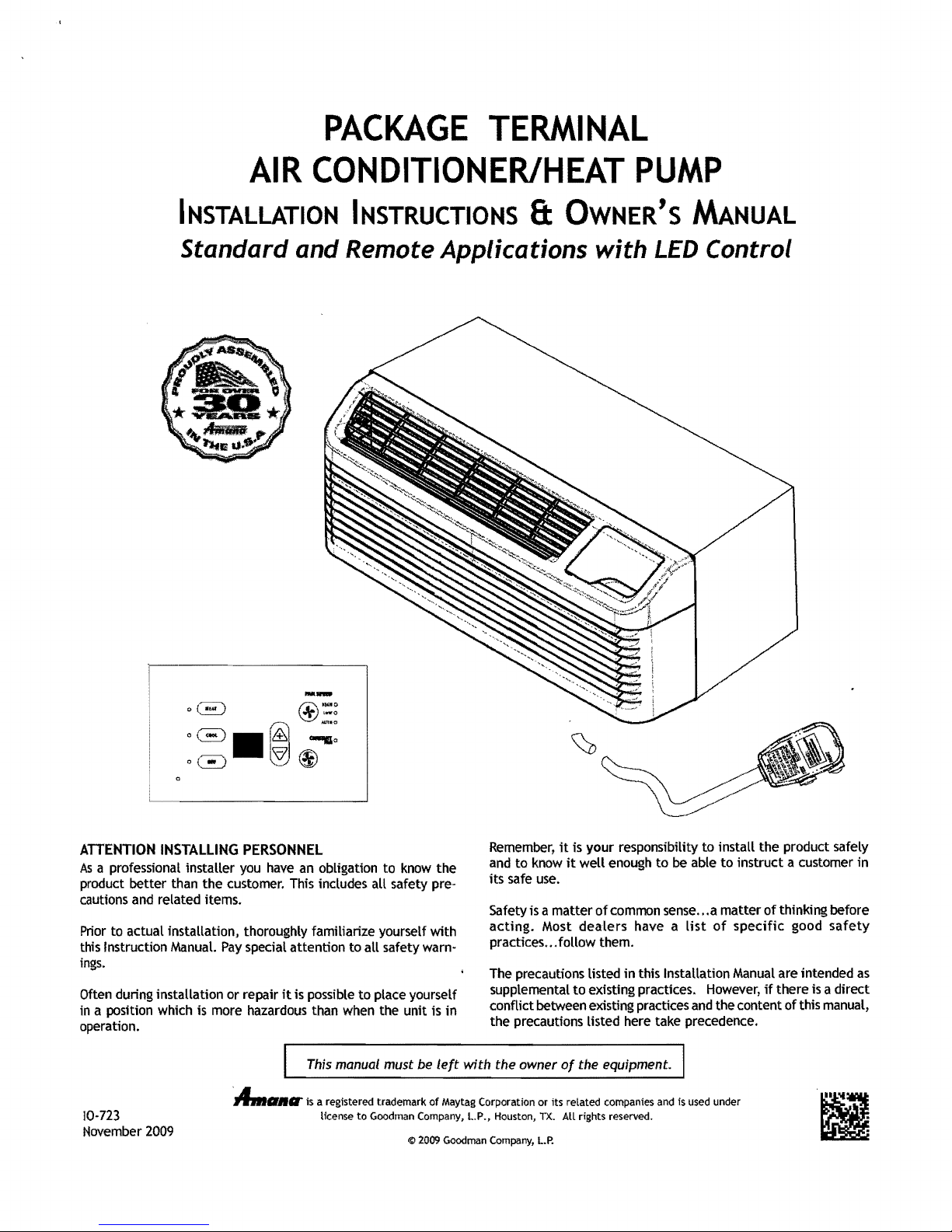
PACKAGE
TERMINAL
AIR
CONDITIONER/HEAT
PUMP
INSTALLATION
INSTRUCTIONS
& OWNER'S MANUAL
Standard and Remote Applications
with
LED
Control
ATTENTION
INSTALLING
PERSONNEL
/ls a professional installer
you
have an obligation to
know
the
product better than
the
customer. This includes
aU
safety pre-
cautions and related items.
Prior
to
actual installation, thoroughly familiarize yourself with
this Instruction Manual.
Pay
special attention to
aU
safety warn-
ings.
Often during installation or repair
it
is possible to place yourself
in
a position which is more hazardous than when the unit is in
operation.
Remember,
it
is your responsibility to install
the
product safely
and
to
know
it
well enough
to
be able
to
instruct a customer
in
its safe use.
Safety is a matter
of
common sense
...a matter
of thinking before
acting.
Most
dealers
have a list
of
specific
good
safety
practices ... follow them.
The precautions listed
in
this Installation Manual
are
intended as
supplemental
to
existing practices.
However,
if
there
is
a direct
conflict between existing practices and
the
content of this manual,
the
precautions listed here take precedence.
This manual must
be
left
with
the owner
Of
the equipment.
:A..
..
II' is a registered trademark
of
May
tag Corporation or its related companies and is used under
license
to
Goodman Company.
L.
P .• Houston,
TX.
All
rights reserved.
November 2009
© 2009 Goodman Company,
L.P.
10-723
Contents
Unit
Features
Installation
..................................................
Instructions
.....................................
2
Wiring ••••••••••••••••••••••••••••••••••••••••••••••••••••••••••• 7
IMPORTANT NOTE
Read
this manual
which must
The precautions listed
supplemental
conflict
manual, the precautions listed here take precedence.
5
be
between existing practices
A
AS A SAFETY
TO
THE SERVICER
and
familiarize yourself
adhered to before attempting
in
this Installation Manual are intended
to
existing practices. However, ifthere is a
RECOGNIZE
and
THIS
with
the content
SYMBOL
PRECAUTION.
the specific items
to
service this unit.
direct
of
as
this
Operating
Maintenance
Obtaining
Normal
Configuration
Configuration
Diagnostic
Diagnostic
IMPORTANT NOTE TO THE OWNER
This manual is
HVAC
sibility
service procedures
person.
IMPORTANT
Your warranty
Read
Keep
find
Instructions
and
Service ••.........................................
Operating
Settings........................
Chart.....
Maintenance
Codes...
to
be
technicians only. Goodman does not
for
property damage
NOTES:
certificate
the
warranty carefully and note
the warranty
it,
if
necessary.
.......................................
Cleaning
Sounds
••••••••
used by qualified, professionally trained
or
certificate
................ ................
and
Conditions
...................................
8:
Status
Report
................
or
personal
services performed by
is also supplied
in
a safe place,
.............
.............
..............
.................
assume
any respon-
injury
for
an
with
the
what
is covered.
so
unqualified
you can
Before using this manual, check the serial plate for
proper model identification.
12
14
14
14
15
16
17
improper
unit.
8
GOODMAN
DAMAGE ARISING FROM IMPROPER SERVICE OR SERVICE PROCEDURES.
IF
RESPONSIBILITY FOR ANY PERSONAL INJURY OR PROPERTY DAMAGE WHICH
MAY RESULT.
SERVICE HEATING AND AIR CONDITIONING EQUIPMENT.
WILL
YOU INSTALL OR PERFORM SERVICE ON THIS UNIT, YOU ASSUME
MANY
AWARNING
NOT BE RESPONSIBLE FOR ANY INJURY OR PROPERTY
JURISDICTIONS REQUIRE A LICENSE
AWARNING
HIGH
VOLTAGE
DISCONNECT
INSTALLING
BE
PRESENT.
DAMAGE,
ALL
POWER
THIS
UNIT.
FAILURE
PERSONAL
BEFORE
MULTIPLE
TO
DO
INJURY
OR
POWER
SO
MAY
DEATH.
SERVICING
SOURCES
CAUSE
PROPERTY
OR
UNIT FEATURES
This
unit
has
many features which are
on conventional
these features
•
LCDI
or
and
the
cords
that
trical
circuit
less. In the event
reset button located on
as
cord
PT
AC
units. The servicer must be
in
order
to
properly service
AFCI
Power Cords - Underwriters Laboratories
National Electric Code (NEe) now require power
sense
current leakage and can open
to
the
unit
that
part
of
the normal troubleshooting procedure.
different
the
on units rated
unit
does not operate, check the
or
near the head
at
TO
INSTALL
OR
than those found
familiar
unit.
250 volts
of
the
the
power
with
elec·
or
THE
INSTALLATION
MUST
BE
NICIANS
Due
right
ONLY.
to policy
is
reserved to
PERFORMED
AND
SERVICING
BY
QUAUFIED,
of
continual product improvement, the
change
OF
THIS
EXPERIENCED
specifications and design
without notice.
EQUIPMENT
TECH-
LCOI
• Automatic 3-minute compressor
2
pressor cycles
• Automatic 2
ture
faUs
reverse cycle heat is shut
turned on.
to
off,
nd
stage
4'F
below
power
it
will
electric
Cord
lockout -After
not restart
heat -If
the
set
point
off
and
the
the com·
for
three minutes.
the room tempera·
temperature, the
electric
strip heat is
• Automatic freeze
protection
- Whenever power is
sup-
plied
to
the
unit
and
the master switch is
in
the
ON
posi-
tion, automatic freeze protection is active.
If
the
unit
senses
temperature below
40°F,
the fan motor
and
elec-
tric
strip heat are turned on. Freeze protection
can
be
turned
off,
if
required.
• Random restart delay -
To
help eliminate power
surges
after a power outage, the
unit
is equipped
with
a two
to
four minute random restart delay feature. Whenever the
unit
is plugged in with the master switch turned
on
and
the mode switch set in the cool or heat mode, a random
restart
will
occur. A random restart condition can be
avoided by setting the mode switch
in
the fan only or
off
poSition before applying power
to
the unit.
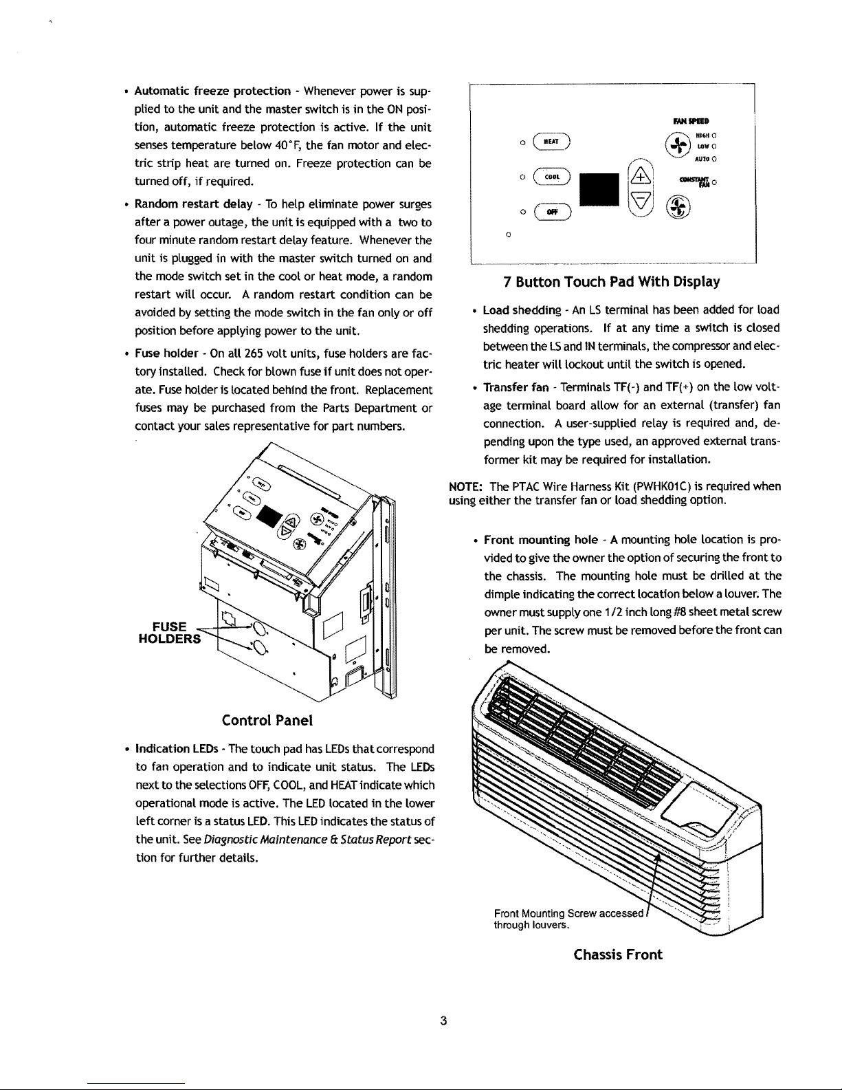
•
Fuse
holder -
On
aU
265
volt
units, fuse holders are fac-
tory installed. Check for blown fuse
if
unit
does not oper-
ate.
Fuse
holder is located behind the front. Replacement
fuses may
be
purchased from the Parts Department
or
contact your
sales
representative
for
part numbers.
FUSE
HOLDERS
Control Panel
• Indication
LEOs
-The touch
pad
has
LEOs
that
correspond
to
fan operation and
to
indicate
unit
status. The
LEOs
next
to
the selections
OFF,
COOL,
and
HEAT
indicate which
operational mode is active. The
LED
located
in
the lower
left
corner is a status
LED.
This
LED
indicates the status
of
the
unit.
See
Diagnostic
Maintenance
Ii
Status
Report
sec-
tion
for
further details.
r::w
H16HO
o~
~
LOWQ
...
-"
AUloQ
1&1
-.0
®®
o
7 Button Touch Pad With Display
• Load shedding -
An
LS
terminal
has
been
added
for
load
shedding operations.
If
at
any time a switch is closed
between the
LS
and
IN
terminals, the compressor
and
elec-
tric
heater
will
lockout
until
the switch is opened.
• Transfer fan - Terminals TF(-) and TF(+)
on
the low volt-
age
terminal board allow for
an
external (transfer) fan
connection. A user-supplied relay is required and, depending upon the
type
used,
an
approved external trans-
former
kit
may
be
required
for
installation.
NOTE:
The
PTAC
Wire
Harness
Kit
(PWHK01C)
is required when
using either the transfer fan
or
load shedding option.
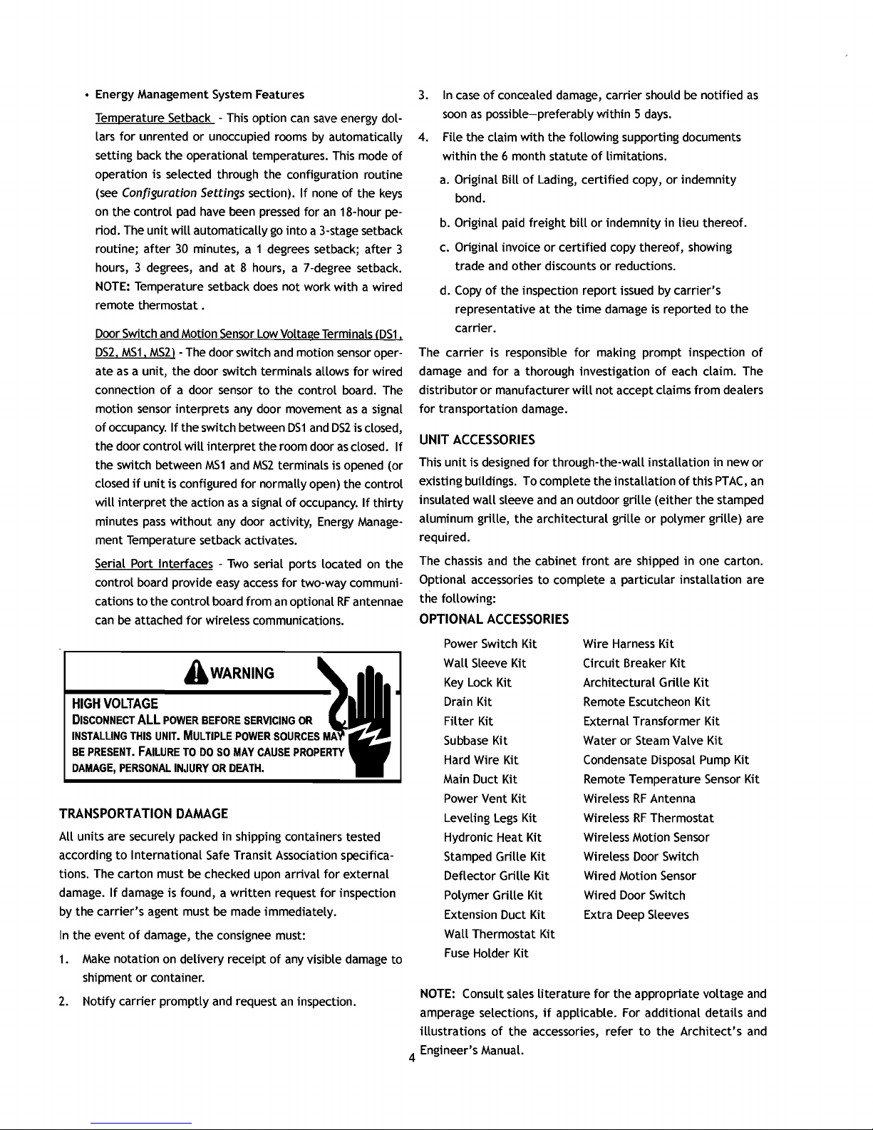
•
Front
mounting hole - A mounting hole location is pro-
vided
to
give the owner the option
of
securing the
front
to
the
chassis.
The mounting hole must be drilled
at
the
dimple indicating the correct location below a louver. The
owner must supply one
1/2
inch long #8 sheet metal screw
per unit. The screw must be removed before the
front
can
be
removed.
Front Mounting Screw accessed
through louvers.
Chassis Front
3
• Energy Management System Features
This
option
can
save
Temperature Setback lars
for
unrented or unoccupied rooms
energy dol-
by
automatically
setting back the operational temperatures. This mode
operation is selected through the configuration routine
(see
Configuration Settings section).
on
the control
riod. The
routine; after
hours, 3 degrees,
NOTE:
pad
have been
unit
will
automatically
30
minutes, a 1 degrees setback; after 3
and
at 8 hours, a 7-degree setback.
Temperature setback
does
If
none
of
pressed
for
go
into
a 3-stage setback
an
18-hour
not work with a wired
the
remote thermostat.
Door
Switch
and
Motion
Sensor
Low
Voltage Terminals
DS2,
MS1,
MS2) -The
as
a unit, the door switch terminals allows for wired
ate
connection
motion
of
occupancy.
of
sensor
the door control
the switch between
if
closed
will
minutes
unit
interpret the action
pass
door switch
a door
sensor
interprets
If
the switch between
will
interpret the room door
MS1
and
and
motion
to
the control board. The
any
door movement
DS1
and
MS2
terminals is opened (or
sensor
as
DS2
as
a signal
is closed,
closed.
is configured for normally open) the control
as
without
a signal
any
door activity,
of
occupancy.
Energy
If
Manage-
ment Temperature setback activates.
Serial Port Interfaces -
control board provide
cations to the control board from
can
be
attached for wireless communications.
Two
serial ports located
easy
access
an
on
for two-way communi-
optional
RF
antennae
AWARNING
HIGH VOLTAGE
DISCONNECT
INSTALLING
BE
PRESENT.
DAMAGE,
TRANSPORTATION DAMAGE
All units are securely packed in shipping containers tested
according
tions. The carton must
damage.
by
the carrier's agent must
In
the event
1.
Make
shipment or container.
2.
Notify carrier promptly
ALL
POWER
BEFORE
THIS
UNIT.
MULTIPLE
FAILURE
PERSONAL
to
International
If
damage is found, a
TO
DO
SO
IN.IURY
OR
Safe
be
checked upon arrival for external
be
of
damage, the consignee must:
notation
on
delivery receipt
and
SERVICING
POWER
MAY
DEATH.
SOURCES
CAUSE
OR
PROPERTY
Transit Association specifica-
written
request for inspection
made immediately.
of
any
visible damage to
request
an
inspection.
3.
4.
of
a.
keys
pe-
b.
c. Original invoice
d.
(DS1
,
oper-
The carrier is responsible for making prompt inspection
damage
distributor
for transportation damage.
UNIT
If
This
existing buHdings. To complete the installation
thirty
insulated wall sleeve
aluminum grille, the architectural grille or polymer grille) are
required.
The
the
Optional accessories to complete a particular installation are
the following:
OPTIONAL
NOTE:
amperage selections,
illustrations
4 Engineer's Manual.
In
case
of
soon
concealed damage, carrier should
as
possible-preferably within 5
days.
be
notified
File the claim with the following supporting documents
within the 6 month statute
Original Bill
of
Lading, certified copy,
of
limitations.
or
indemnity
bond.
Original paid freight
and
trade
Copy
other discounts or reductions.
of
the inspection report issued
representative
bill
or indemnity in lieu thereof.
or
certified copy thereof, showing
by
carrier's
at
the time damage is reported to the
carrier.
and
for
a thorough investigation
or
manufacturer
ACCESSORIES
unit
is designed for through-the-wall installation in new or
chassis
and
the cabinet
ACCESSORIES
will
not accept claims from dealers
and
an
outdoor grille (either the stamped
front
Power Switch Kit Wire
of
are shipped
Harness
Kit
each claim. The
of
this
PTAC,
in
one carton.
Wall Sleeve Kit Circuit Breaker Kit
Key
Lock Kit
Architectural Grille Kit
Drain Kit Remote Escutcheon Kit
Filter Kit External Transformer Kit
Subbase
Hard Wire Kit Condensate Disposal
Main Duct Kit Remote Temperature
Power Vent Kit Wireless
Leveling
Hydronic Heat Kit Wireless Motion
Kit Water or Steam Valve Kit
Pump
Sensor
RF
Antenna
Legs
Kit Wireless
RF
Thermostat
Sensor
Stamped Grille Kit Wireless Door Switch
Deflector Grille Kit Wired Motion
Sensor
Polymer Grille Kit Wired Door Switch
Extension Duct Kit Extra
Deep
Sleeves
Wall Thermostat Kit
Fuse
Holder Kit
Consult sales literature for the appropriate voltage
if
applicable. For additional details
of
the accessories, refer
to
the Architect's
as
of
an
Kit
Kit
and
and
and
INSTALLATION
INSTRUCTIONS
To
ensure
that
the unit operates safely and efficiently,
it
must
be installed, operated and maintained according to these instal·
lation and operating instructions and all local codes and ordi·
nances or,
in
their absence, with the latest edition of
the
National Electric Code. The proper installation of this unit
is
described
in
the
following sections. Following the steps
in
the
order presented should ensure proper installation.
A
WARNING
HIGH
VOLTAGE
DISCONNECT
ALL
POWER BEFORE SERVICING.
MULTIPLE POWER SOURCES MAY
BE
PRESENT. FAILURE
TO
DO
SO
MAY
CAUSE PROPERTY DAMAGE, PERSONAL
INJURY OR DEATH.
Do
NOT SERVICE THIS UNIT WITHOUT FIRST
ENSURING THAT:
THE
ELECTRICAL ACCESSORIES ARE INSTALLED
ONLY
IN THE
PRE-DRILLED MOUNTING HOLES.
THE
ELECTRICAL WIRING IS NOT INSTALLED AND DOES NOT HANG
BELOW
THE PRE-DRILLED MOUNTING HOLE
OR
LIE IN THE UNIT
BASE PAN.
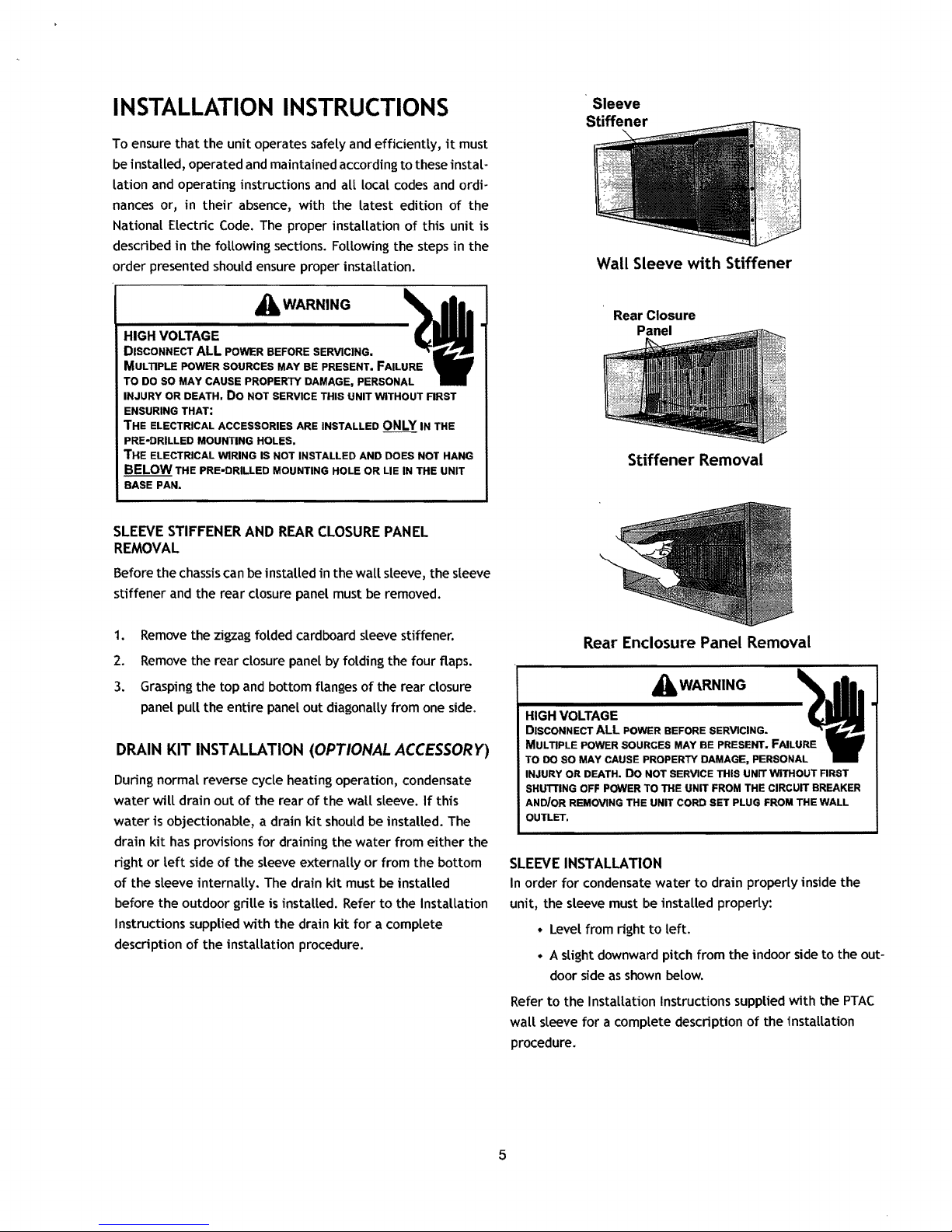
SLEEVE
STIFFENER
AND
REAR
CLOSURE
PANEL
REMOVAL
Before
the
chassis can
be
installed
in
the
wall sleeve, the sleeve
stiffener and the rear closure panel must
be
removed.
1.
Remove
the zigzag folded cardboard sleeve stiffener.
2.
Remove
the rear closure panel
by
folding the four flaps.
3.
Grasping the top and bottom flanges of the rear closure
panel pull
the
entire panel out diagonally from one side.
DRAIN
KIT
INSTALLATION
(OPTIONAL
ACCESSORy)
During
normal reverse cycle heating operation, condensate
water will drain out of
the
rear of
the
wall sleeve.
If
this
water is objectionable, a drain kit should be installed. The
drain kit has provisions for draining
the
water from either the
right or left side of the sleeve externally
or
from
the
bottom
of the sleeve internally. The drain kit must
be
installed
before
the
outdoor grille
is
installed. Refer
to
the Installation
Instructions supplied with
the
drain kit for a complete
description of
the
installation procedure.
Wall Sleeve
with
Stiffener
Stiffener Removal
Rear Enclosure Panel Removal
A
WARNING
HIGH
VOLTAGE
DISCONNECT
ALL
POWER BEFORE SERVICING.
MULTIPLE POWER SOURCES MAY
BE
PRESENT. FAILURE
TO
DO
SO MAY CAUSE PROPERTY DAMAGE, PERSONAL
INJURY OR DEATH.
Do
NOT SERVICE THIS
UNrr
WITHOUT ARST
SHUTTING
OFF
POWER TO THE
UNrr
FROM THE CIRCUIT BREAKER
ANDloR
REMOVING THE UNIT CORD SET PLUG FROM THE
wALL
OUTLET.
SLEEVE
INSTALLATION
In
order for condensate water
to
drain properly inside
the
unit, the sleeve must be installed properly:
•
Level
from
right
to
left.
• A slight downward pitch from the indoor side to
the
out-
door side as shown
below.
Refer
to
the
Installation Instructions supplied with the
PTAC
wall sleeve for a complete description of the installation
procedure.
5

Outside
_______
Wall
Level
JI
-\
1/4
Bubble
Tilt
Outside
To
Proper Sleeve
OUTDOOR
An
outside grille must
unit
be
installed before installing the
tion Instructions supplied
complete description
This
a Polymer Grille Kit (Model
(Model
grille or
check with your
chassis
An
improper outdoor grille
capacity, increase energy
possibly void the warranty.
FRONT
1.
GRILLE
be
installed to direct
operation
model requires either a Stamped Grille Kit (Model
and
also
protect the outdoor coil. The grille must
with
of
the installation procedure.
PGK)
AGK--B).
using
should
When
replacing
a specialized grille in a new installation, please
sales
representative
be
used
with
the non-standard specialized grille.
can
usage
REMOVAL
Grasp
the cabinet front.
Tilt
chassis.
the outdoor grille
or
an
decrease cooling
and
Refer
an
Architectural Grille Kit
old
chassis
to
determine
shorten compressor
air
flow for proper
to
the Installa-
kit
with
an
if
or
for
SGK--B),
existing
the new
heating
life
and
a
Cabinet Front Removal View 2
Front Mounting Screw accessed
through louvers.
Cabinet Front Removal View 1
2.
Pull the bottom
until the retaining clips disengage.
cured
with a screw,
follow front removal procedure.
of
the cabinet front away from the
remove front mounting
NOTE:
If
front is
screw,
chassis
se-
then
3.
Lift
to
CHASSIS
1.
Remove
Front
2.
Insert the
6
Front Mounting Screw
the cabinet front
reinstall the cabinet front.
INSTALLATION
the cabinet front from the
Removal.
chassis
Chassis
off
the
into
the wall sleeve.
Installation View 1
chassis.
Wall Sleeve
Reverse
chassis
this procedure
as
described in

3. Slide the
flanges contact the
(3
chassis
Screws
on
each
into
the
front
wall
edge
sleeve
until
of
the
wall
Wall Sleeve
the
chassis
sleeve.
TO
AVOID
ELECTRICAL SHOCK,
PROPERTY
A CAUTION
DAMAGE,
DO
NOT
PERSONAL
USE
AN
EXTENSION
INJURY
OR
CORD
DEATH
WITH
DUE
THIS
TO
UNIT.
iC':~~-
~.--
Outside
Wall
Chassis Installation View 2
4. Secure the
each side
the
in
a plastic
IMPORTANT
1. The
pressor. These grommets are factory set and require no adjustment.
If
a standard subbase is used, be sure
2.
cover is removed before
3.
On
the subbase cover extension
4.
Check the indoor and outdoor grilles
flow. The
trees,
the
unit,
rapidly. This could damage the compressor
the
WIRING
of
chassis
NOTES:
unit
is equipped
230Y,
30A
unit
or
other
unit.
If
the
air
warranty_
chassis
to
the
wall
sleeve using three screws on
the chassis
and
the
bag
attached
units installed
to
ensure a proper seal between
wall
sleeve. The screws are supplied
to
the power cord.
with
a rubber grommet mounted com-
the
right hand subbase
the
chassis is installed
with
an
existing subbase, use
in
kit.
for
obstructions
must be located where curtains, furniture,
objects do not block the
air is obstructed
and/or
air
flow
deflected back
conditioner compressor may cycle on and
or
possibly void
A WARNING
the sleeve.
to
to
and
from
into
the
A CAUTION
To
AVOID
THE
RISK
OF
USE
ONLY
COPPER
PROPERTY
CONDUCTORS.
A CAUTION
To
AVOID THE RISK OF PROPERTY DAMAGE, PERSONAL INJURY OR
FIRE,
00
NOT INSTALL WITH POWER CORD STRETCHED OR UNDER A
MA
STRAIN AS THIS
CONNECTION.
To
AVOID
MUST
BE
Cord connection
units.
All
265-volt units must be hard wired using the hard
kit
or
make use
subbase.
2301208Vand 115V units are equipped
cords and can open the
unit
the
air
near the head
does
shooting procedure.
...---------A---------------.
off
THIS
AIR
CONDITIONER
UFE
SUPPORT
THE
FAILURE
THE
FAILURE
HEAT
IN
THE
PERSONS
OR
PRECAUTIONS
OCCURRENCE.
Y CREATE A LOOSE PLUG/RECEPTACLE
A CAUTION
THE
RISK
OF
PROPERLY
not
of
FOR
OF
THIS
OF
AN
CONDITIONED
ANIMALS.
MUST
PERSONAL
POLARIZED
to a wall
of
the
electrical
operate, check the reset button located on
the power cord
..
IS
NOT
PERSONS
OR
PRODUCT.
UNATTENDED
SPACE
BE
TAKEN
DAMAGE,
socket is
INJURY,
AND
GROUNDED.
PERSONAL
WIRING
not
permitted
plug-in receptacle
with
circuit
to
the
as
part
of
WARNING
MEANT
TO
PROVIDE
ANIMALS
AIR
CAUSING
TO
WARN
CONDmONER
UNATTENDED
WHO
ARE
OVERHEATING
OFF
OR
GUARD
INJURY
OR
FIRE,
TO
THE
UNIT
for
265-volt
wire
in
the standard
LCDI
or
AFCI
power
unit.
In
the
event
the normal trouble-
UNABLE
MAY
COOUNG
TO
REACT
RESULT
OR
DEATH
AGAINST
IN
EXTREME
OF
SUCH
TO
AN
or
OR
HIGH VOLTAGE
DISCONNECT
MULTIPLE POWER SOURCES MAY BE PRESENT. FAILURE
TO
DO so MAY CAUSE PROPERTY DAMAGE, PERSONAL
INJURY
Do
NOT SERVICE THIS UNIT WITHOUT FIRST SHUTIING OFF
POWER TO
REMOVING THE UNIT CORD SET PLUG
OR
ALL
POWER BEFORE SERVICING.
DEATH.
THE
UNIT
FROM
THE CIRCUIT BREAKER AND/OR
FROM
THE WALL OUTLET.
THE
PTAC
WIRE
See PTAC
HARNESS
Wire Harness Kit Installation Instructions
KIT
wire orientation and location
HEATERLESS
If
a heaterless
UNITS
unit
is ordered,
adding supplemental heat. Refer
with
the
kit
for
supplied
tion
procedures. All 2081230
with a 15
Amp power cord.
a complete description
7
(PWHK01C)
for
low
voltage wiring.
field
provisions must be made
to
the
Installation Instructions
of
volt
heaterless units are shipped
for
proper
for
the installa-
VOLTAGE
Once
Voltage must
Table
MEASUREMENTS
the
unit
is properly wired, measure the
fall
within the voltage utilization range given
2.
unit
supply voltage.
in
Operating Voltage
Unit Voltage
Rating Minimum
230/208 197
265
115
Voltage Utilization Range
Maximum
253
238
103.5
292
126.5
Table 2 - Operating Voltage
OPERATING INSTRUCTIONS
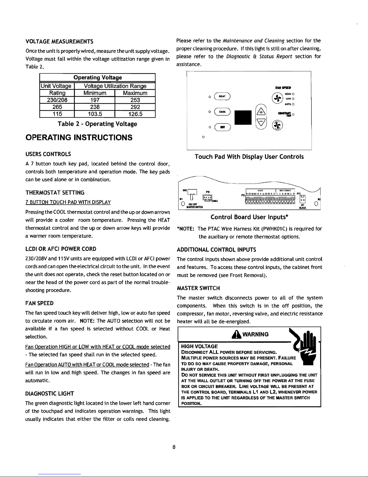
USERS
CONTROLS
A 7 button touch key pad, located behind the control door,
controls both temperature and operation mode.
can
be
used
alone or in combination.
The
key
pads
Please refer
proper cleaning procedure.
please refer
assistance.
to
to
o
Touch
the Maintenance and Cleaning section for the
the Diagnostic
Pad
With Display User Controls
If
this light is
still
8:
Status Report section for
"\
ffi
~
~I~
on
after
Q
"1<"0
~
LOWO
••
CllllS'll'fAo
cleaning,
'00
THERMOSTAT
7 BUnON
Pressing
will
provide a cooler room temperature.
thermostat control and the up
a warmer room temperature.
LCDI
OR
230/208Vand 115V units are equipped
cords and
the unit does not operate, check the reset button located
near the head
shooting procedure.
FAN
SPEED
The fan speed touch key
to circulate room air.
available
selection.
Fan
Operation
The
selected fan
Fan
Operation
will
run
automatic.
DIAGNOSTIC
The
green diagnostic
of
the touch pad and indicates operation warnings. This
usually indicates
SETTING
TOUCH
the
AFCI
can
if
in
PAD
WITH
DISPLAY
COOL
thermostat control and the up
or
down arrow
POWER
open the electrical
of
a fan speed is selected
HIGH
AUTO
low and high speed. The changes
CORD
the power cord
will
deliver high, low
NOTE:
or
LOW
with
speed
shall run
with
HEAT
circuit
as
part
The
AUTO
HEAT
in
the selected speed.
or
COOL
LIGHT
light
that
located
either
the
in
the lower
filter
or
down arrows
Pressing
with
LCDI
to
the unit.
of
the normal trouble-
selection
without
or
COOL
mode selected -The fan
or coils need cleaning.
the
keys
will
provide
or
AFCI
In
the event
or
auto fan speed
will
COOL
or
mode selected
in
fan
speed
left
hand corner
HEAT
power
on
or
not
be
Heat
are
light
Control Board User Inputs·
*NOTE: The
ADDITIONAL
The control inputs shown above provide additional
and features. To
must
be
MASTER
The master switch disconnects power
components.
compressor, fan motor, reversing valve,
heater
HIGH VOLTAGE
DISCONNECT
MULTIPLE POWER SOURCES MAY BE PRESENT. FAILURE
TO DO SO MAY CAUSE PROPERTY DAMAGE, PERSONAL
INJURY OR DEATH.
Do NOT SERVICE THIS UNIT WITHOUT FIRST UNPLUGGING THE UNIT
AT
THE WALL OUTLET OR TURNING OFF THE POWER
BOX OR CIRCUIT BREAKER.
THE CONTROL BOARD, TERMINALS L 1 AND
IS APPLIED TO THE UNIT REGARDLESS OF THE MASTER SWITCH
POSITION.
PTAC
Wire
Harness
the
auxiliary or remote thermostat options.
CONTROL
access
these control inputs, the cabinet
removed (see Front Removal).
Kit
INPUTS
(PWHK01C)
SWITCH
When
will
this switch is
all
be
de-energized.
A
ALL
POWER BEFORE SERVICING.
LINE
WARNING
in
VOLTAGE WILL
is required
unit
to
all
of
the system
the
off
position, the
and
electric
AT
THE FUSE
BE
L2,
PRESENT
WHENEVER POWER
resistance
for
control
front
AT
8

REMOTE
CONTROL
INPUTS
The
C,
R,
GL,
W2,
YIW1,
6/0,
and
GH
terminals provide control
inputs for a "manufacturer-approved" remote wall mounted
thermostat. The
"6"
terminal
can
be
configured
to
become
"0"
if
needed
see
Configuration Settings
For
remote control thermo-
stat operation, refer
to
the Remote Thermostat Operation
section.
FRONT
DESK
CONTROL
(FD1, FD2,
EH,
IN)
The
FD1 t FD2,
EH
and
IN
terminals provide control inputs
for
a
front
desk switch. Shorting
across
the
FD1
and
FD2
terminals
will
disable unit operation. The only control function which
will
remain active when these terminaLs are shorted is freeze protection.
Any
switch which
will
produce a short circuit
across
these
two
terminals can
be
used
as a front
desk switch. The contact
resistance
of
the Switch, when closed, must
be
less
than
200
ohms
for
the front desk feature
to
operate properly. Table 3
shows
the maximum wire length
and
corresponding
gage
size
for
installation
of a front
desk switch. The following figure
shows
a
wiring schematic for connecting the
front
desk switch
to
the
unit.
If
the
unit
is configured
for
wired unrented setback energy
management
(see
Configuration Settings section c2),
EH
and
IN
terminals are
used
instead
of
FD1
and
FD2.
If
EH
and
IN
are
shorted, the unit
will
go
into
setback temperatures
for
cooLing
and heating
as
configured in c3
and
c4
(see
Configuration
Settings).
Unit operation
will
be
disabled.
"Fd"
(see
Diagnostic
Codes)
will
appear on the
dispLay.
This allows the room to quickLy
recover
to
a comfortable temperature when the room is occu-
pied.
Table 3 - Maximum Wire Length
for
Front
Desk Switch
~
o
IAT
BLACK
FRONT
DESK
SWTCH
Front
Desk
Switch Wiring Schematic
No holes are permitted in chassis basepan
or
wallsleeve when routing low voltage wire. Route the
low voltage wires through the indention on the front
of
the basepan.
Low Voltage Wires Routing
VENT
CONTROL
The vent controL allows outside
air
to
be
drawn into the
conditioned area. This outside
air
can provide ventiLation when
the blower is operating, but
it
will
increase the heating
or
cooling
Load
and
operating costs.
To obtain
access
to
the vent control:
1.
Remove
the cabinet front
(see
Front
RemovaL).
2.
Remove
the shipping screw
(if
installed) from the vent
door.
3.
Remove
the
Label
(if
present) from over the vent control
Lever
on
the
left
side
of
the
chassis.
Remove
the vent door
shipping
screw.
9

4.
Rotate
the vent control lever
damper.
Vent
Control
Lever
to
either
open
or
Vent
Control
Lever
Vent
Control
close
the
Use
the following procedure
air flow:
1.
Remove
2.
Position the front
Discharge
3.
Remove
grille to the cabinet front.
the front cabinet
Air
Flow
the four
Location
to
change the angle
(see
so
that the backside
(4)
screws
which
of
4 Screws
Front
Removal).
is
accessible.
secure
the discharge air
of
the discharge
,'
,'I
'1
........
,:'
I,
,:'
.:'
,-
..........
"
r:,
'
.........
Vent Vent
Open Closed
Vent
Door
Lever
Positions
Hydronic Heat Installations
To
avoid the risk
prolonged shut down periods, the vent door must
when the outdoor temperature might
AIR
DISCHARGE
The
discharge grille
or
40 0 angle.
of
freezing the steam or water coil during
fall
below freezing.
GRILLE
can
be
adjusted to expel air
15%
Discharge'
Air
be
at
either a
left
closed
15
Discharge
4. Rotate the grille
5.
Reinstall the screws securing the discharge air grille to the
cabinet front. Reinstall the cabinet front
REMOTE
To
operate this
thermostat, configure the control
thermostat. Enter configuration mode
Code
in the remote mode, the
inputs (terminal strip positions
shown
configuration
control touchpad
0
ration
unit
the
NOTE:
random restart feature
active
THERMOSTAT
This
unit
thermostats. For further information
for
use
For best performance results, the thermostat should
approximately five
inside wall in
Air
Flow
Grille
Removal
180 0 clockwise.
THERMOSTAT
unit
with a "manufacturer-approved" remote
to
be
operated
C1
and
L5
(see
Configuration Settings in back
unit
will
only respond
GL
(or
GH),
in
"Control
and
at
In
remote mode, the 3-minute compressor time delay, the
(see
Board
User
Inputs" illustration).
C1
with option code
will
no
longer accept inputs other than configu-
diagnostics modes. The room occupant must operate
the remote mounted thermostat.
and
the freeze protection feature are all
Unit Features section).
L5
has
LOCATION
is designed
with
this unit, contact your sales representative.
an
area
to
be
operated
feet
above the floor
with
good
with
remote wall mounted
on
thermostats approved
on
air circulation.
on
the unit.
by
the remote
then select option
of
manual).
to
the thermostat
W2,
Y /W1,
been
selected, the
a vibration free,
NOTE:
be
located
When
and
Once
B*
Discharge
Grille
Orientation
Options
10
 Loading...