

Page 1
OT18-60A OUTDOOR THERMOSTAT
A
INSTALLATION INSTRUCTIONS
ATTENTION INSTALLING PERSONNEL
As a professional installer you have an obligation to know the
product better than the customer. This includes all safety precautions and related items.
Prior to actual installation, thoroughly familiarize yourself with
this Instruction Manual. Pay special attention to all safety warnings. Often during installation or repair it is possible to place
yourself in a position which is more hazardous than when the
unit is in operation.
Remember, it is your responsibility to install the product safely
and to know it well enough to be able to instruct a customer in
its safe use.
Safety is a matter of common sense...a matter of thinking before acting. Most dealers have a list of specific good safety
practices...follow them.
The precautions listed in this Installation Manual are intended
as supplemental to existing practices. However, if there is a
direct conflict between existing practices and the content of
this manual, the precautions listed here take precedence.
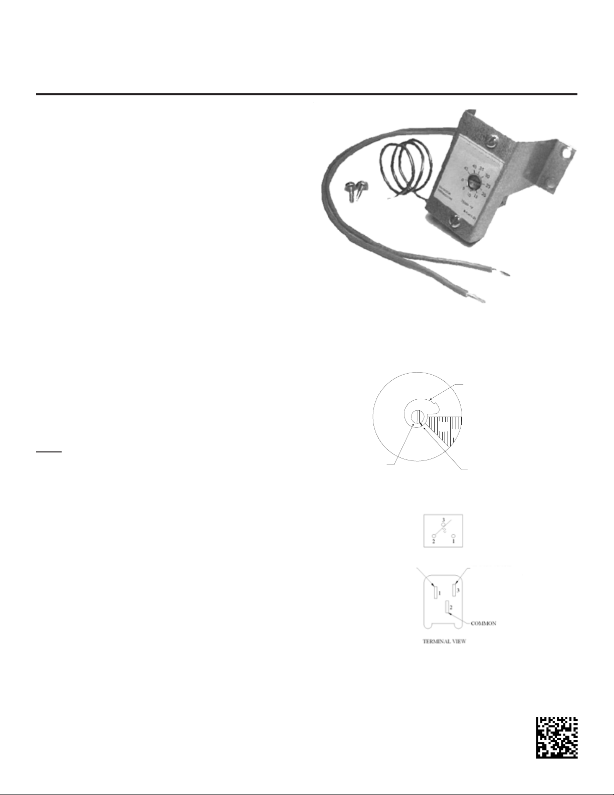
DESCRIPTION
This single pole double throw thermostat device with adjustable 0° to 45° temperature range is employed in conjunction
with the room thermostat to control the electric heaters that
have been added to cooling and heat pump products. This kit
includes an Outdoor Thermostat, three wires, mounting bracket,
(3) wire caps, and (2) self-drilling screws.
Note: If the outdoor ambient temperature is below 0° F (-18°
C) with 50% or higher Relative Humidity, an Outdoor Thermostat must be installed and set at (0º F) on the dial. Failure to
comply wth this requirement may result in damage to the product which may not be covered by the manufacturer’s warranty.
See Figures 12 and 15 for wiring connections.
The schematic and the terminal view of this device is shown in
Figure 2:
When used as an outdoor thermostat to control increments of
electric heat, connections will be made to terminals 2 and 1.
As temperature rises above the set point contacts 2 to 1 will
open thus preventing the controlled increment of supplemental
heat from operating. As outdoor temperature falls below the
set point contacts 2 to 1 will close allowing the controlled increment of heat to operate. See Figures 10, 11, 13, and 14 for
wiring connections.
Use the wires supplied for Outdoor Thermostat connections. If
the installation is with an All Fuel kit, refer to the Installation
Instructions supplied with the AFE18 All Fuel kit for wiring connections.
INSTALLATION
The outdoor thermostat is designed to be installed in the space
allocated in the control box of the cooling and heat pump units.
OT18-60
Thermo stat
315º
Set Point
djustment
Screw
THERMOSTAT CAM
Normally Open
Contacts 2-1
Close On
Temperature Fall
PART # B13708-67
DEAD
DIAL
Figure 1
Figure 2
Dial
COLD
WARM (Turn Counterclockwi se)
45º
Set Point
Indicator
Mark
(Shown @ Oº F)
Normally Closed
Contacts 2-3
Open On
Temperature Fall
(Turn Clockwise)
IO-510E
10/2013
Page 2
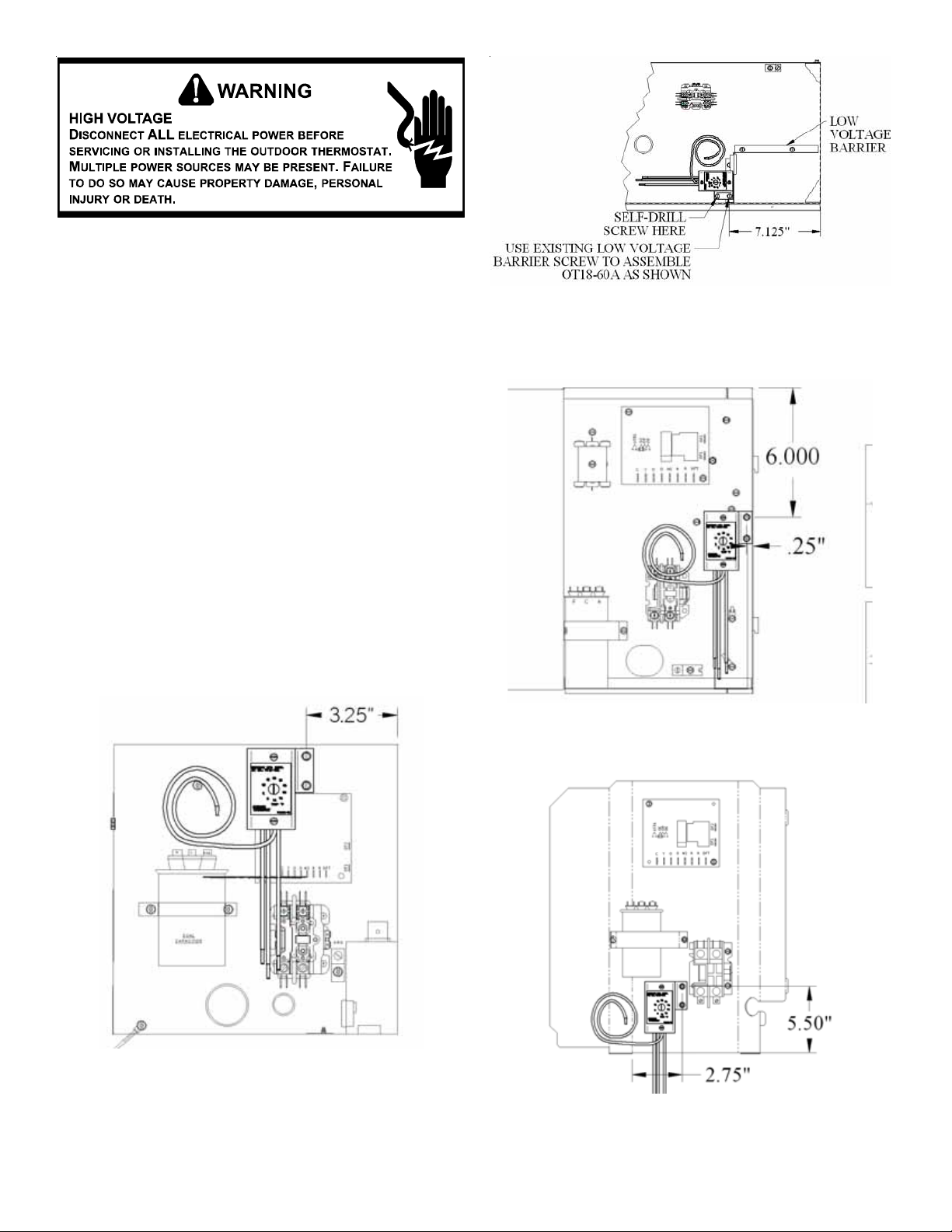
1. Remove the sheet metal screws securing the unit control
box cover.
2. Install the OT18-60A Outside Thermostat using the supplied bracket and self-drilling screws (see Figures 3 through
9.). NOTE: Early split, packaged cooling and heat pump
units, refer to Figures 3 through 6. AS*, D*, GS* and SS*
split cooling and heat pump units, refer to Figures 7 and
8. AP*, GP*, DP* packaged cooling and heat pump unit s,
refer to Figure 9.
3. Wire the thermostat per Figures 10, 11, 12, 13, 14, and
15.
4. Route the capillary away from live terminals to prevent
electrical shorts.
NOTE: Outdoor Thermostat copper capillary will remain
inside of the control box on early models. On AS*, D*,
GS*, SS*, AP*, GP* and DP* models, the capillary will
extend outside the control box.
5. Set installed thermostat(s) to the proper outdoor temperature. Insert a screwdriver in slot of thermostat dial (Figure 1). Turn set point indicator as shown in figure to desired temperature setting on label (counterclockwise for
WARM, clockwise for COLD).
6. Reinstall the control box cover.
EARLY
PACKAGE SYSTEM COOLING
AND HEAT PUMP
Figure 4
GOODMAN® BRAND
DAIKIN D***SN
AMANA® BRAND AN* MODELS
SPLIT SYSTEM HEAT PUMP
Figure 3
AMANA® BRAND
REMOTE HEAT PUMP
Figure 5
AMANA® BRAND
DAIKIN D***SA, D***TC
REMOTE HEAT PUMP
Figure 6
2
Page 3
TEST
1991
C
90
K2
A60
30
O R
DEF.
CONTROL
CONTACTOR
.180
XFMR
°
L1
L2
T2T1
K1
DF2
O
DFTW2Y
RC
DF1
OT18
GOODMAN MFG. CORP.
KIT NO.: OT18-60A
USE LINE ON CAM TO SELECT TEMPERATURE
OUTDOOR
THERMOSTAT
45
0
40
5
TEMP ºF
35
10
0140K00041P
30
15
20
25
POWER
ALERT
TRIP
COMFORT
ALERT
MODULE
Y
C
R
CAP
CONTACTOR
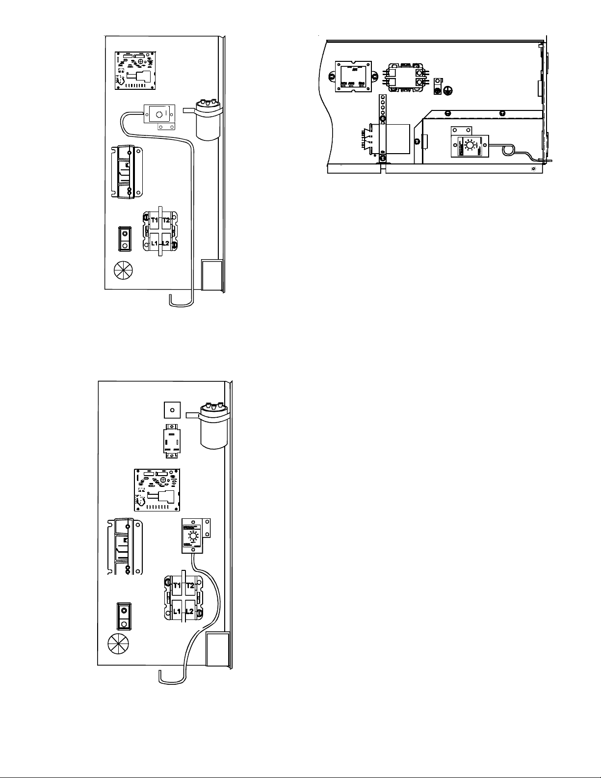
ANX*, ANZ*, ASC*, ASH*, ASX*, ASZ*, GSC*,
GSH*,SSX*, SSZ, DX*, DZ*
SERIES SMALL BOX SPLIT SYSTEM COOLING AND HEAT
PUMPS
Figure 7
TIME
DELAY
CAP
OT18
APC*, APH*, GPC*, GPH*, DP*C*, DP*H*
SERIES PACKAGED SYSTEM
COOLING AND HEAT PUMPS
Figure 9
4
FAN
RELAY
2 5
1 3
CAP
TEST
K1
1991
C
O
O R
DEF.
DF2
DFTW2Y
RC
DF1
OT18
POWER
ALERT
TRIP
COMFORT
ALERT
MODULE
90
K2
A60
30
CONTROL
Y
C
R
CONTACTOR
ASX*, ASZ*, DX**SA*, DZ**SA*SERIES LARGE BOX
SPLIT SYSTEM COOLING AND HEAT PUMPS
Figure 8
3
Page 4

SPLIT SYSTEM WIRING DIAGRAM - SINGLE STAGE ELECTRIC HEAT
10 KW & BELOW
SEE NO TE 4
SEE
NOTE
3
OUTDOOR UNIT
W2COYR
B
W
O
L
U
E
Y
H
R
E
I
A
L
N
T
L
E
G
O
E
W
R
E
D
R
TYPICAL H/P
ROOM THERMOSTAT
C W1 G
O
Y
R E
Y
O
W
SEE NOTE 1
#18 GA. 7 WIRE
R
G
BR
INDOOR UNIT
R
R
RED
G
G
GREEN
W2
W
WHITE
Figure 10
BL
21
R
BL
SEE NOTE 4
TYPICAL H/P
ROOM THERMOSTAT
O R E
C
Y
W2
#18 GA 6 WIRE
SEE NOTE 3
G
W1
R
(OPTIONAL)
OUTDOOR THERMOSTAT
CLOSE ON TEMPERATURE FALL
SPLIT SYSTEM WIRING DIAGRAM - TWO-STAGE ELECTRIC HEAT
ABOVE 10 KW
SEE
NOTE
3
OUTDOOR UNIT
YR
W2CO
W
O
B
L
U
E
Y
R
H
E
A
I
L
T
N
L
E
G
O
E
W
R
E
D
Y
O
BL
W
W
BR
BL
SEE NOTE #2
#18 GA. 6 WIRE NEEDED WHEN OT IS USED
BL
C
BLUE
Figure 11
SEE NOTE 1
#18 GA. 8 WIRE
INDOOR UNIT
R
R
G
RRED
G
G
W2
W
W3
BR
GREEN
WHITE
BROWN
C
BL
SEE NOTE #2
SEE
NOTE
5
NOTES:
1) "O" AND "E" USED ON HEAT PUMPS ONLY.
2) TERMINAL BLOCK MARKINGS ARE FOR AMANA®
AIR HANDLERS
3) "R", "O" AND "W2" CONNECTIONS REQUIRED ON
HEAT PUMPS ONLY.
4) "R" CONNECTION REQUIRED ON AMANA® AC UNITS
WITH COMFORT ALERT MODULE.
R
OUTDOOR THERMOSTAT
CLOSE ON TEMPERATURE FALL
21
BL
#18 GA. 6 WIRE
FOR HEAT PUMPS
SEE NOTE 3
5) CONNECT WIRE FROM TERMINAL #2 OF
OUTDOOR THERMOSTAT TO THE WHITE
WIRE ON THE INDOOR UNIT IF A SINGLE
STAGE INDOOR THERMOSTAT IS USED.
BL
Wiring is subject to change. Always refer to the wiring diagram on the unit for the most up-to-date wiring.
4
BLUE
COLOR CODES
R --RED
Y --YELLOW
BL-BLUE
BR-BROWN
O --ORANGE
W -WHITE
G --GREEN
Page 5

N
N
SPLIT SYSTEM WIRING DIAGRAM - HEAT PUMPS ONLY!
ABOVE 10 kW
TWO-STAGE ELECTRIC HEAT
Figure 12
HEAT PUMP
W2
B
R
I
R
R
TYPICAL H/P
ROOM THERM OSTAT
C
R
#18 GA. 8 WIRE
INDO OR UNIT
R
RED
R
Y
G
G
G
GREEN
O
BL
W
Y
#18 GA. 5 WIRE
BA
BR
BR
W
BL
SEE NOTE #1
W
BR
BL
W2
W3
C
WHITE
BROW N
BLUE
BLR
OUTDOOR THERMOSTAT #1
CLOSE ON TEMPERATURE FALL
R
BL
OUTDOOR
THERMOSTAT #2
(IF USED, SEE
NOTE 2)
For outdoor temperatures below 0° F with 50% or higher relative humidity,set outdoor
thermostat at 0° F
OTE 1: TERMINAL BLOCK MARKINGS ARE FOR AMANA® BRAND & DAIKIN (DV**PTC) AIRHANDLERS.
.
OTE 2: CONNECT OT18 #2 BETWEEN W2 OF THERMOSTAT AND BROWN WIRE ON INDOOR UNIT IF USED.
Wiring is subject to change. Always refer to the wiring diagram on the unit for the most up-to-date wiring.
5
Page 6

PACKAGE SYSTEM WIRING DIAGRAM - SINGLE STAGE ELECTRIC HEAT
ABOVE 10 KW
TYPICAL H/P
ROOM THERMOSTAT
YOCW1GRE
SEE NOTE 1
#18 GAUGE 7 WIRE
PACKAGE UNIT
Figure 13
R
Y
G
O
BR
R
BL
BL
R
Y
G
O
W
BL
12
OUTDOOR THERMOSTAT
CLOSE ON TEM PERATURE FALL
PACKAGE SYSTEM WIRING DIAGRAM - TWO-STAGE ELECTRIC HEAT
ABOVE 10 KW
TYPICAL H/P
ROOM THERMOSTAT
W2 C RYO W1G E
SEE NOTE 1
#18 GAUGE 8 WIRE
PACKAGE UNITS
R
Y
G
RED
YELLOW
GREEN
ORANGE
WHITE
BLUE
Figure 14
RED
R
YELLOW
Y
G
GREEN
SEE
NOTE 2
W
O
BR
R
BL
O
W
BR
BL
ORANGE
WHITE
BROWN
BLUE
12
OUTDOOR THERMOSTAT
CLOSE ON TEMPERATURE FALL
NOTES:
1) "O" AND "E" USED ON HEAT PUMPS ONLY.
2) IF SINGLE STAGE INDOOR THERMOSTAT IS USED, CONNECT WIRE FROM TERMINAL #1
TO THE WHITE WIRE ON PACKAGE UNITS.
LOW VOLTAGE
JUNCTION BOX
Color Codes
R - Red
Y - Yellow
BL - Blue
BR - Brown
O - Orange
W - White
G - Green
Wiring is subject to change. Always refer to the wiring diagram on the unit for the most up-to-date wiring.
6
Page 7

PACKAGE SYSTEM WIRING DIAGRAM - HEAT PUMPS ONLY!
ABOVE 10 kW
TWO-STAGE ELECTRIC HEAT
TYPICAL H/P
ROOM THERMOSTAT
W2 C RYO W1G E
OUTDOOR THERMOSTAT #2
(IF USED, SEE NOTE 1)
R
BL
W
12
Y
3
BL
12
OUTDOOR THERMOSTAT #1
CLOSE ON TEMPERATURE FALL
#18 GAUGE 8 WIRE
PACKAGE HEAT PUMP
R
Y
G
O
BR
BL
RED
R
YELLOW
Y
G
GREEN
ORANGE
O
W
WHITE
BROWN
BR
BL
BLUE
LOW VOLTAGE
JUNCTION BOX
Figure 15
For outdoor temperature s belo w 0° F with 50% or higher relativ e hu mi dity,set outdoor
thermostat at 0° F
NOTE 1: OT18 #2 CAN BE CONNECTED BETWEEN W2 OF THERMOSTAT AND BROWN WIRE IF DESIRED.
.
COLOR CODES
R --RED
Y --YELLOW
BL-BLUE
BR-BROWN
O --ORANGE
W -WHITE
G --GREEN
Wiring is subject to change. Always refer to the wiring diagram on the unit for the most up-to-date wiring.
7
Page 8

NOTE: SPECIFICATIONS AND PERFORMANCE DATA LISTED HEREIN ARE SUBJECT TO CHANGE WITHOUT NOTICE
Quality Makes the Difference!
All of our systems are designed and manufactured with the same high quality standards regardless of size or
efficiency . We have designed these unit s to significantly reduce the most frequent causes of product failure.
They are simple to service and forgiving to operate. We use quality materials and components. Finally , every
unit is run tested before it leaves the factory . That’ s why we know. . .There’s No Better Quality.
Visit our website at www.daikincomfort.com, www.goodmanmfg.com or www.amana-hac.com for information on:
• Products
• Warranties
• Customer Services
• Parts
• Contractor Programs and Training
• Financing Options
5151 San Felipe, Suite 500, Houston, TX 77056
© 2003-2006, 2013 Goodman Manufacturing Company, L.P.
is a registered trademark of Maytag Corporation or its related companies and is used under license. All rights reserved.
8
 Loading...