

Page 1

*MEC96
TABLE OF CONTENTS
PFLOW
U
/ H
ORIZONTAL
GAS F
T
URNACE
WO-STAGE
(Type FSP CATEGORY IV Direct
or Non Direct Vent Air Furnace)
These furnaces comply with requirements embodied in the American National Standard / National Standard of Canada ANSI Z21.47·CSA-2.3
Gas Fired Central Furnaces.
Installer:
Affix all manuals
adjacent to the unit.
s a professional installer you have an obligation to know
A
the product better than the customer. This includes all safety
precautions and related items.
Prior to actual installation, thoroughly familiarize yourself
with this Instruction Manual. Pay special attention to all
safety warnings. Often during installation or repair it is
possible to place yourself in a position which is more
hazardous than when the unit is in operation.
Remember, it is your responsibility to install the product
safely and to know it well enough to be able to instruct a
customer in its safe use.
Safety is a matter of common sense...a matter of thinking
before acting. Most dealers have a list of specific good
safety practices...follow them.
The precautions listed in this Installation Manual are intended
as supplemental to existing practices. However, if there is
a direct conflict between existing practices and the content
of this manual, the precautions listed here take precedence.
RECOGNIZE THIS SYMBOL
AS A SAFETY PRECAUTION.
SAFETY CONSIDERATIONS .................................... 2
HIPPING INSPECTION ............................................ 4
S
LECTROSTATIC DISCHARGE (ESD) PRECAUTIONS ................... 4
E
T
O THE INSTALLER .............................................. 5
PRODUCT DESCRIPTION ......................................... 5
EATURES ....................................................... 5
F
PRODUCT APPLICATION ......................................... 5
LOCATION REQUIREMENTS & CONSIDERATIONS ........... 6
LEARANCES AND ACCESSIBILITY ................................... 7
C
EXISTING FURNACE REMOVAL ..................................... 8
HERMOSTAT LOCATION .......................................... 8
T
C
OMBUSTION & VENTILATION AIR REQUIREMENTS .................. 9
INSTALLATION POSITIONS ...................................... 9
ORIZONTAL APPLICATIONS & CONSIDERATIONS ..................... 9
H
URNACE SUSPENSION ..........................................10
F
RONT COVER PRESSURE SWITCH TUBE LOCATION ................10
F
D
RAIN TRAP AND LINES ......................................... 10
HORIZONTAL FURNACE LEVELING ................................ 10
ALTERNATE ELECTRICAL AND GAS LINE CONNECTIONS ............. 10
DRAIN PAN ....................................................10
FREEZE PROTECTION ............................................10
PROPANE GAS/HIGH ALTITUDE INSTALLATIONS .......... 10
VENT/FLUE PIPE & COMBUSTION AIR PIPE .................11
UAL CERTIFICATION: NON-DIRECT/DIRECT VENT ................ 11
D
MATERIALS AND JOINING METHODS .............................. 11
PROPER VENT/FLUE AND COMBUSTION AIR PIPING PRACTICES ..... 12
TERMINATION LOCATIONS ........................................12
ANADIAN VENTING REQUIREMENTS ..............................13
C
STANDARD FURNACE CONNECTIONS .............................. 13
VENT/FLUE PIPE .............................................. 13
NON-DIRECT VENT (SINGLE PIPE) PIPING ........................15
VENT/INTAKE TERMINATIONS FOR INSTALLATION
MULTIPLE DIRECT VENT FURNACES ........................18
OF
CONCENTRIC VENT TERMINATION .................................18
SIDE WALL VENT KIT ..........................................18
CONDENSATE DRAIN LINES & DRAIN TRAP .................18
G
ENERAL DRAIN INFORMATION ...................................18
FIELD SUPPLIED DRAIN ......................................... 19
UPFLOW MODEL INSTALLED VERTICALLY ..........................19
DRAIN EXITING RIGHT SIDE ..................................... 19
DRAIN EXITING LEFT SIDE ...................................... 20
UPFLOW MODEL INSTALLED HORIZONTALLY
RIGHT SIDE DOWN ..................................... 20
WITH
UPFLOW MODEL INSTALLED HORIZONTALLY
LEFT SIDE DOWN ...................................... 20
WITH
*NOTE: Please contact your distributor or our website for
the applicable Specification Sheet referred to in this manual.
5151 San Felipe Suite 500
Houston, TX 77056
IOG-2011F
04/2016
www.goodmanmfg.com • www.amana-hac.com
© 2014 - 2016 Goodman Manufacturing Company, L.P.
is a registered trademark of Maytag Corporation or its related companies and is used under license. All rights reserved.
Page 2
ELECTRICAL CONNECTIONS ...................................21
W
IRING HARNESS ...............................................21
115 V
OLT LINE CONNECTIONS ..................................21
JUNCTION BOX RELOCATION ..................................... 21
OLT THERMOSTAT WIRING ..................................22
24 V
S
INGLE-STAGE HEATING THERMOSTAT APPLICATION ................23
OSSIL FUEL APPLICATIONS ......................................23
F
T
WINNING .....................................................23
115 VOLT LINE CONNECTION OF ACCESSORIES
(HUMIDIFIER AND ELECTRONIC AIR CLEANER) ..................23
GAS SUPPLY AND PIPING .......................................24
H
IGH ALTITUDE DERATE.........................................24
ROPANE GAS CONVERSION .....................................24
P
G
AS PIPING CONNECTIONS ...................................... 25
PROPANE GAS TANKS AND PIPING ................................26
CIRCULATING AIR & FILTERS ..................................27
D
UCT WORK - AIR FLOW ....................................... 27
C
HECKING DUCT STATIC ......................................... 27
OTTOM RETURN AIR OPENING [UPFLOW MODELS] ..............28
B
F
ILTERS - READ THIS SECTION BEFORE INSTALLING
THE RETURN AIR DUCT WORK ................................28
PRIGHT INSTALLATIONS ......................................... 29
U
H
ORIZONTAL INSTALLATIONS ......................................30
STARTUP PROCEDURE & ADJUSTMENT ......................30
D
RAIN TRAP PRIMING ........................................... 30
FURNACE OPERATION ........................................... 30
GAS SUPPLY PRESSURE MEASUREMENT ........................... 31
GAS MANIFOLD PRESSURE MEASUREMENT AND ADJUSTMENT ....... 32
GAS INPUT RATE MEASUREMENT (NATURAL GAS ONLY)........... 32
TEMPERATURE RISE .............................................33
CIRCULATOR BLOWER SPEEDS ...................................33
DIP SWITCH SETTINGS ......................................... 34
BLOWER HEAT OFF DELAY TIMINGS .............................40
NORMAL SEQUENCE OF OPERATION .........................40
P
OWER UP ....................................................40
H
EATING MODE ................................................40
COOLING MODE ................................................41
AN ONLY MODE ..............................................41
F
OPERATIONAL CHECKS .........................................41
SAFETY CIRCUIT DESCRIPTION ...............................41
I
NTEGRATED CONTROL MODULE .................................41
RIMARY LIMIT ................................................. 41
P
A
UXILIARY LIMIT ................................................41
ROLLOUT LIMIT ................................................42
RESSURE SWITCHES ............................................ 42
P
F
LAME SENSOR ................................................42
T
ROUBLESHOOTING ............................................. 42
E
LECTROSTATIC DISCHARGE (ESD) PRECAUTIONS ..................42
C
HECKING FLAME SENSOR ...................................... 42
LIMIT FAULT CODES ............................................ 42
IAGNOSTIC CHART ............................................. 43
D
F
AULT RECALL ................................................. 43
ESETTING FROM LOCKOUT .....................................44
R
MAINTENANCE ...................................................44
A
NNUAL INSPECTION ............................................ 44
FILTERS ........................................................ 44
BURNERS ...................................................... 45
INDUCED DRAFT AND CIRCULATOR BLOWERS ......................45
CONDENSATE TRAP AND DRAIN SYSTEM (QUALIFIED SERVICER ONLY)45
FLAME SENSOR (QUALIFIED SERVICER ONLY) .................... 45
FLUE PASSAGES (QUALIFIED SERVICER ONLY) .................... 45
BEFORE LEAVING AN INSTALLATION .........................45
REPAIR AND REPLACEMENT PARTS ...........................46
TROUBLESHOOTING CHART...................................47
WIRING DIAGRAM ...............................................49
SPECIAL INSTRUCTIONS FOR PRODUCTS INSTALLED
IN THE STATE OF MASSACHUSETTS ..................50
S
AFETY
Adhere to the following warnings and cautions when installing,
adjusting, altering, servicing, or operating the furnace. To
ensure proper installation and operation, thoroughly read this
manual for specifics pertaining to the installation and application of this product.
C
ONSIDERATIONS
WARNING
G
OODMAN
DAMAGE ARISING FROM IMPROPER SERVICE OR SERVICE PROCEDURES
F YOU INSTALL OR PERFORM SERVICE ON THIS UNIT, YOU ASSUME
I
RESPONSIBILITY FOR ANY PERSONAL INJURY OR PROPERTY DAMAGE
WHICH MAY RESULT
INSTALL OR SERVICE HEATING AND AIR CONDITIONING EQUIPMENT
WILL NOT BE RESPONSIBLE FOR ANY INJURY OR PROPERTY
. M
ANY JURISDICTIONS REQUIRE A LICENSE TO
.
.
This furnace is manufactured for use with natural gas. It may
be field converted to operate on L.P. gas by using the appropriate L.P. conversion kit listed in the PROPANE GAS/HIGH ALTITUDE INSTALLATIONS section of this manual
Install this furnace only in a location and position as specified in LOCATION REQUIREMENTS & CONSIDERATIONS section and
INSTALLATION POSITIONS section of this manual.
Provide adequate combustion and ventilation air to the furnace as specified in COMBUSTION & VENTILATION AIR REQUIRE-
MENTS section of this manual.
2
Page 3
Combustion products must be discharged to the outdoors.
Connect this furnace to an approved vent system only, as
specified in VENT/FLUE PIPE & COMBUSTION AIR PIPE section of this manual.
Never test for gas leaks with an open flame. Use a commercially available soap solution made specifically for the detection of leaks to check all connections, as specified in
GAS
SUPPLY AND PIPING section of this manual.
Always install a furnace to operate within the furnace’s intended temperature-rise range with a duct system which has
external static pressure within the allowable range, as specified on the furnace rating plate and
OPERATIONAL CHECKS
section of these instructions.
When a furnace is installed so that supply ducts carry air
circulated by the furnace to areas outside the space containing the furnace, the return air shall also be handled by duct(s)
sealed to the furnace casing and terminating outside the
space containing the furnace.
CAUTION
FROZEN AND BURST WATER PIPE HAZARD
F
AILURE TO PROTECT AGAINST THE RISK OF FREEZING MAY RESULT IN
PROPERTY DAMAGE
S
PECIAL PRECAUTIONS
AREA WHICH MAY DROP BELOW FREEZING
OPERATION OR DAMAGE TO EQUIPMENT
ENVIRONMENT HAS THE POTENTIAL OF FREEZING, THE DRAIN TRAP AND
DRAIN LINE MUST BE PROTECTED
HEATERS, ELECTRIC HEAT TAPE AND/OR
RECOMMENDED FOR THESE INSTALLATIONS
.
MUST BE
MADE IF INSTALLING FURNACE IN AN
. T
HIS CAN CAUS E IMPROPER
. IF
THE FURNACE
. THE
USE OF ACCESSORY DRAIN TRAP
RV
ANTIFREEZE IS
.
A gas-fired furnace for installation in a residential garage
must be installed as specified in the
LOCATION REQUIRE-
MENTS AND CONSIDERATIONS section of this manual.
This furnace may be used as a construction site heater only
if certain conditions are met. These conditions are listed in
the PRODUCT APPLICATION section of this manual.
WARNING
IF
THE INFORMATION IN THESE INSTRUCTIONS IS NOT FOLLOWED
EXACTLY, A FIRE OR EXPLOSION MAY RESULT CAUSING PROPERTY
DAMAGE
,
PERSONAL INJURY OR LOSS OF LIFE
DO
NOT STORE OR USE GASOLINE OR OTHER FLAMMABLE VAPORS AND
LIQUIDS IN THE VICINITY OF THIS OR ANY OTHER APPLIANCE
.
.
WHAT TO DO IF YOU SMELL GAS:
D
O NOT TRY TO LIGHT ANY APPLIANCE
D
O NOT TOUCH ANY ELECTRICAL SWITCH; DO NOT USE ANY PHONE
IN YOUR BUILDING
I
MMEDIATELY CALL YOUR GAS SUPPLIER FROM A NEIGHBOR’S
PHONE
. F
I
F YOU CANNOT REACH YOUR GAS SUPPLIER, CALL THE FIRE
DEPARTMENT
I
NSTALLATION AND SERVICE MUST BE PERFORMED BY A QUALIFIED
INSTALLER, SERVICE AGENCY OR THE GAS SUPPLIER
.
OLLOW THE GAS SUPPLIER’S INSTRUCTIONS
.
.
.
.
WARNING
T
HIS PRODUCT CONTAINS OR PRODUCES A CHEMICAL OR CHEMICALS
WHICH MAY CAUSE SERIOUS ILLNESS OR DEATH AND WHICH ARE
KNOWN TO THE STATE OF CALIFORNIA TO CAUSE CANCER, BIRTH
DEFECTS OR OTHER REPRODUCTIVE HARM
.
WARNING
H
EATING UNIT SHOULD NOT BE UTILIZED WITHOUT REASONABLE
ROUTINE, INSPECTION, MAINTENANCE AND SUPERVISION
BUILDING IN WHICH ANY SUCH DEVICE IS LOCATED WILL BE VACANT
CARE SHOULD BE TAKEN THAT SUCH DEVICE IS ROUTINELY INSPECTED
MAINTAINED AND MONITORED. IN THE EVENT THAT THE BUILDING
MAYBE EXPOSED TO FREEZING TEMPERATURES AND WILL BE VACANT
ALL WATER-BEARING PIPES SHOULD BE DRAINED, THE BUILDING SHOULD
BE PROPERLY WINTERIZED, AND THE WATER SOURCE CLOSED. IN THE
EVENT THAT THE BUILDING MAY BE EXPOSED TO FREEZING
TEMPERATURES AND WILL BE VACANT, ANY HYDRONIC COIL UNITS
SHOULD BE DRAINED AS WELL AND, IN SUCH CASE, ALTERNATIVE HEAT
SOURCES SHOULD BE UTILIZED
.
. IF
THE
,
,
,
,
WARNING
WARNING
TO
PREVENT PERSONAL INJURY OR DEATH DUE TO IMPROPER
INSTALLATION, ADJUSTMENT, ALTERATION, SERVICE OR MAINTENANCE
REFER TO THIS MANUAL
INFORMATION, CONSU LT A QUALIFIED INSTALLER, SERVICER AGENCY OR
THE GAS SUPPLIER
. FOR
ADDITIONAL ASSISTANCE OR
.
TO
PREVENT POSSIBLE PROPERTY DAMAGE, PERSONAL INJURY OR
DEATH DUE TO ELECTRICAL SHOCK, THE FURNACE MUST BE LOCATED TO
PROTECT THE ELECTRICAL COMPONENTS FROM WATER
,
Drain trap must be primed at time of installation. Trap is
.
internally partitioned; add water to both inlet ports until water appears at both sides of the outlet opening. Failure to
prime trap at time of installation may have a negative effect on combustion quality and pressure switch action.
3
Page 4
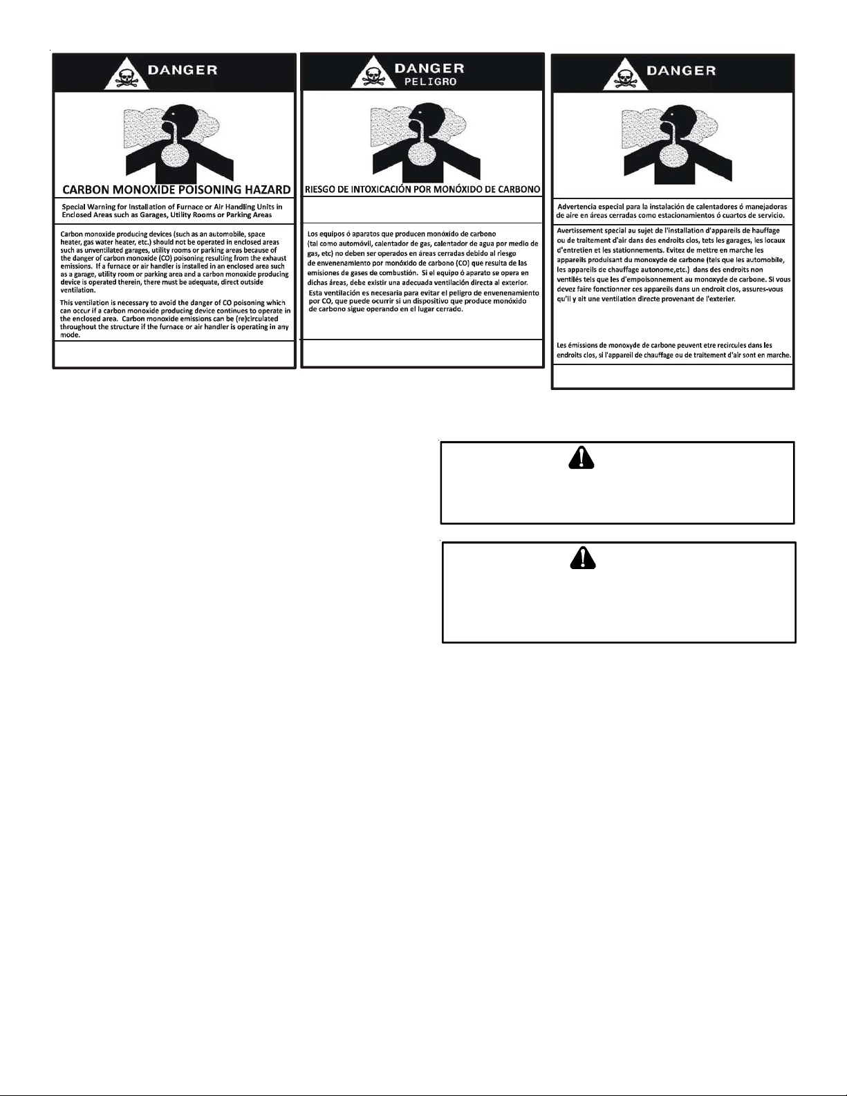
Advertencia especial para la instalación de calentadores ó manejadoras
de aire en áreas cerradas com o estacionamient os ó cuartos de ser vicio.
RISQUE D'EMPOISONNEMENT AU
MONOXYDE DE CARBONE
Cette ventilation est nécessaire pour éviter le danger d'intoxication
au CO po uvant surveni r si un appare il produisant du monoxyde
de carbon e conti nue de fonctionner au sei n de la zon e confi née.
Le monoxyde de
des
dommag es pe rmanents au cerve au et meme la mor t.
carbone peut causer des maladies graves telles que
CO can cause serious illness including perma nent brain
damage or death.
B10259-216
Las emis ione s de monóxido de carbono pueden circular a través
del aparat o cuando se opera en cualquier modo.
El monóx ido de carbono pu ede causar enferme dades severas
como daño cerebral p ermanente ó m uerte.
B10259-216
SHIPPING I NSPECTION
All units are securely packed in shipping containers tested according to International Safe Transit Association specifications. The
carton must be checked upon arrival for external damage. If damage is found, a request for inspection by carrier’s agent must be
made in writing immediately.
S
HOULD OVERHEATING OCCUR OR THE GAS SUPPLY FAIL TO SHUT OFF
TURN OFF THE MANUAL GAS SHUTOFF VALVE EXTERNAL TO THE
FURNACE BEFORE TURNING OFF THE ELECTRICAL SUPPLY
The furnace must be carefully inspected on arrival for damage and
bolts or screws which may have come loose in transit. In the event
of damage the consignee should:
1. Make a notation on delivery receipt of any visible damage to
shipment or container.
2. Notify carrier promptly and request an inspection.
3. With concealed damage, carrier must be notified as soon as
possible - preferably within five days.
P
OSSIBLE PROPERTY DAMAGE, PERSONAL INJURY OR DEATH DUE TO
FIRE, EXPLOSION, SMOKE, SOOT, CONDENSATION, ELECTRICAL SHOCK
OR CARBO N MONOXIDE MAY RESULT FROM IMPROPER INSTALLATION
REPAIR OPERATION, OR MAINTENANCE OF THIS PRODUCT
4. File the claim with the following support documents within a
nine month statute of limitations.
• Original or certified copy of the Bill of Lading, or indemnity bond.
• Original paid freight bill or indemnity in lieu thereof.
• Original or certified copy of the invoice, showing trade and other discounts or reductions.
• Copy of the inspection report issued by carrier’s representative at the time damage is reported to carrier.
WARNING
WARNING
B10259-216
,
.
,
.
The carrier is responsible for making prompt inspection of damage and for a thorough investigation of each claim. The distributor or
manufacturer will not accept claims from dealers for transportation damage.
ELECTROSTATIC DISCHARGE (ESD) PRECAUTIONS
NOTE: Discharge your body’s static electricity before touching unit. An electrostatic discharge can adversely affect electrical
components.
Use the following precautions during furnace installation and servicing to protect the integrated control module from damage. By
putting the furnace, the control, and the person at the same electrostatic potential, these steps will help avoid exposing the
integrated control module to electrostatic discharge. This procedure is applicable to both installed and non-installed (ungrounded)
furnaces.
1. Disconnect all power to the furnace. Do not touch the integrated control module or any wire connected to the control prior to
discharging your body’s electrostatic charge to ground.
2. Firmly touch a clean, unpainted, metal surface of the furnaces near the control. Any tools held in a person’s hand during
grounding will be discharged.
4
Page 5
3. Service integrated control module or connecting wiring following the discharge process in step 2. Use caution not to recharge
your body with static electricity; (i.e., do not move or shuffle your feet, do not touch ungrounded objects, etc.). If you come
in contact with an ungrounded object, repeat step 2 before touching control or wires.
4. Discharge your body to ground before removing a new control from its container. Follow steps 1 through 3 if installing the
control on a furnace. Return any old or new controls to their containers before touching any ungrounded object.
TO THE INSTALLER
Before installing this unit, please read this manual thoroughly to
familiarize yourself with specific items which must be adhered to,
including but not limited to: unit maximum external static pressure, gas pressures, BTU input rating, proper electrical connections, circulating air temperature rise, minimum or maximum CFM,
and motor speed connections.
P
RODUCT DESCRIPTION
TO
PREVENT PROPERTY DAMAGE, PERSONAL INJURY OR DEATH DUE TO
FIRE, DO NOT INSTALL THIS FURNACE IN A MOBILE HOME, TRAILER, OR
RECREATIONAL VEHICLE
WARNING
.
FEATURES
The *MEC96 furnace may be installed upflow or horizontally with left or right side down. The *MEC96 two-stage gas furnace
features a multi-speed ECM indoor fan motor, two heating inputs (W1 & W2), two cooling inputs (YLO & Y) and a two stage
gas valve. A single stage heating thermostat may also be used in conjunction with timed transition to high fire by the furnace
integrated control board.
P
RODUCT APPLICATION
This furnace is primarily designed for residential home-heating applications. It is NOT designed or certified for use in mobile homes,
trailers or recreational vehicles. Neither is it designed or certified for outdoor applications. The furnace must be installed indoors
(i.e., attic space, crawl space, or garage area provided the garage area is enclosed with an operating door).
This furnace can be used in the following non-industrial commercial applications:
Schools, Office buildings, Churches, Retail stores, Nursing homes, Hotels/motels, Common or office areas
In such applications, the furnace must be installed with the following stipulations:
• It must be installed per the installation instructions provided and per local and national codes.
• It must be installed indoors in a building constructed on site.
• It must be part of a ducted system and not used in a free air delivery application.
• It must not be used as a “make-up” air unit.
• It must be installed as a two-pipe system for combustion air.
• All other warranty exclusions and restrictions apply This furnace is an ETL dual-certified appliance and is appropriate for use
with natural or propane gas (NOTE: If using propane, a propane conversion kit is required).
Dual certification means that the combustion air inlet pipe is optional and the furnace can be vented as a:
Non-direct vent (single pipe) central forced air furnace in which combustion air is taken from the installation area or from air
ducted from the outside or,
Direct vent (dual pipe) central forced air furnace in which all combustion air supplied directly to the furnace burners through
a special air intake system outlined in these instructions.
This furnace may be used as a construction site heater ONLY if all of the following conditions are met:
• The vent system is permanently installed per these installation instructions.
• A room thermostat is used to control the furnace. Fixed jumpers that provide continuous heating CANNOT be used and can
cause long term equipment damage. Bi-metal thermostats, or any thermostat affected by vibration must not be used
during construction.
• Return air ducts are provided and sealed to the furnace.
• A return air temperature range between 60ºF (16ºC) and 80ºF (27ºC) is maintained.
• Air filters are installed in the system and replaced daily during construction and upon completion of construction.
• The input rate and temperature rise are set per the furnace rating plate.
• The furnace must be installed as a two pipe system, using 100% outside air for combustion during construction.
5
Page 6
• The furnace heat exchanger, components, duct system, air filters and evaporator coils are thoroughly cleaned following final
construction clean up by a qualified person.
• All furnace operating conditions (including ignition, input rate, temperature rise and venting) are verified by a qualified
person according to these installation instructions.
• Furnace doors must be in place on the furnace while the furnace is operating in any mode.
• Damage or repairs due to failure to comply with these requirements are not covered under the warranty.
NOTE: The Commonwealth of Massachusetts requires that the following additional requirements must also be met:
• Gas furnaces must be installed by a licensed plumber or gas fitter.
• A T-handle gas cock must be used.
• If the unit is to be installed in an attic, the passageway to and the service area around the unit must have flooring.
To ensure proper furnace operation, install, operate and maintain the furnace in accordance with these installation and
operation instructions, all local building codes and ordinances. In their absence, follow the latest edition of the National Fuel Gas
Code (NFPA 54/ANSI Z223.1), and/or CAN/CSA B149.1-15 Installation Codes, local plumbing or waste water codes, and other
applicable codes.
A copy of the National Fuel Gas Code (NFPA 54/ANSI Z223.1) can be obtained from any of the following:
American National Standards Institute National Fire Protection Association CSA International
25 West 43rd Street, 4th Floor 1 Batterymarch Park 8501 East Pleasant Valley
New York, NY 10036 Quincy, MA 02169-7471 Independence, OH 44131
The rated heating capacity of the furnace should be greater than or equal to the total heat loss of the area to be heated. The total
heat loss should be calculated by an approved method or in accordance with “ASHRAE Guide” or “Manual J-Load Calculations”
published by the Air Conditioning Contractors of America.
A copy of the CAN/CSA B149.1-15 Installation Codes can also be obtained from:
CSA International
178 Rexdale Boulevard
Etobicoke, Ontario, Canada M9W 1R3
L
OCATION REQUIREMENTS
& C
ONSIDERATIONS
Follow the instructions listed below and the guidelines provided in the Combustion and Ventilation Air Requirements section when
selecting a furnace location.
WARNING
TO
PREVENT POSSIBLE EQUIPMENT DAMAGE, PROPERTY DAMAGE
PERSONAL INJURY OR DEATH, THE FOLLOWING BULLET POINTS MUST BE
OBSERVED WHEN INSTALLING THIS UNIT
.
,
P
OSSIBLE PROPERTY DAMAGE, PERSONAL INJURY OR DEATH DUE TO
FIRE, EXPLOSION, SMOKE, SOOT, CONDENSATION, ELECTRICAL SHOCK
OR CARBO N MONOXIDE MAY RESULT FROM IMPROPER INSTALLATION
REPAIR OPERATION, OR MAINTENANCE OF THIS PRODUCT
WARNING
,
.
• Centrally locate the furnace with respect to the proposed or existing air distribution system.
• Ensure the temperature of the return air entering the furnace is between 55°F and 100°F when the furnace is heating.
• Provide provisions for venting combustion products outdoors through a proper venting system. Special consideration
should be given to vent/flue pipe routing and combustion air intake pipe when applicable. Refer to Vent/Flue Pipe and
Combustion Air Pipe -Termination Locations for appropriate termination locations and to determine if the piping system
from furnace to termination can be accomplished within the guidelines given. NOTE: The length of flue and/or combustion
air piping can be a limiting factor in the location of the furnace.
• Locate the furnace so condensate flows downwards to the drain. Do not locate the furnace or its condensate drainage
system in any area subject to below freezing temperatures without proper freeze protection. Refer to Condensate Drain
Lines and Trap for further details.
• Ensure adequate combustion air is available for the furnace. Improper or insufficient combustion air can expose building
occupants to gas combustion products that could include carbon monoxide. Refer to Combustion and Ventilation Air
Requirements.
• Set the furnace on a level floor to enable proper condensate drainage. If the floor becomes wet or damp at times, place the
furnace above the floor on a concrete base sized approximately 1-1/2" larger than the base of the furnace. Refer to the
Horizontal Applications and Considerations for leveling of horizontal furnaces.
• Ensure upflow or horizontal furnaces are not installed directly on carpeting, or any other combustible material. The only
combustible material allowed is wood.
6
Page 7
• Exposure to contaminated combustion air will result in safety and performance-related problems. Do not install the furnace
where the combustion air is exposed to the following substances:
permanent wave solutions chlorinated waxes or cleaners chlorine-based
carbon tetrachloride water softening chemicals swimming pool chemicals
deicing salts or chemicals halogen type refrigerants
cleaning solutions (such as perchloroethylene) printing inks
paint removers varnishes hydrochloric acid
cements and glues antistatic fabric softeners for clothes dryers
• Seal off a non-direct vent furnace if it is installed near an area frequently contaminated by any of the above substances. This
protects the non-direct vent furnace from airborne contaminants. To ensure that the enclosed non-direct vent furnace has
an adequate supply of combustion air, vent from a nearby uncontaminated room or from outdoors. Refer to the Combustion
and Ventilation Air Requirements for details.
• If the furnace is used in connection with a cooling coil unit, install the furnace upstream or in parallel with the cooling coil
unit. Premature heat exchanger failure will result if the cooling unit is placed ahead of the furnace.
For vertical applications, the minimum cooling coil width shall not be less than furnace width minus 1”.
For upflow applications, the front of the coil and furnace must face the same direction.
• If the furnace is installed in a residential garage, position the furnace so that the burners and ignition source are located not
less than 18 inches (457 mm) above the floor. Protect the furnace from physical damage by vehicles.
• If the furnace is installed horizontally, ensure the access doors are not on the “up/top” or “down/bottom” side of the
furnace.
• Do not connect this furnace to a chimney flue that serves a separate appliance designed to burn solid fuel.
CLEARANCES AND ACCESSIBILITY
NOTES:
• For servicing or cleaning, a 24” front clearance is required.
• Unit connections (electrical, flue and drain) may necessitate greater clearances than the minimum clearances listed
above.
• In all cases, accessibility clearance must take precedence over clearances from the enclosure where accessibility
clearances are greater.
Installations must adhere to the clearances to combustible materials to which this furnace has been design certified. The minimum
clearance information for this furnace is provided on the unit’s
clearance label. These clearances must be permanently maintained.
Clearances must also accommodate an installation’s gas, electrical, and drain trap and drain line connections. If the alternate
combustion air intake or vent/flue connections are used additional
clearance must be provided to accommodate these connections.
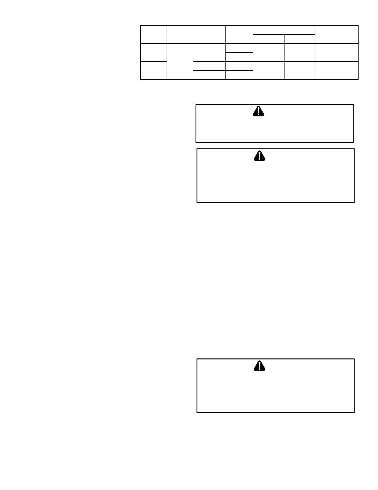
*MEC96 MINIMUM CLEARANCES TO COMBUSTIBLE MATERIALS
(INCHE S)
POSITION* SIDE S REA R FRONT BOTTOM FLUE TOP
Upflow 0" 0" 3" C 0" 1"
Ho rizon tal 6" 0" 3" C 0" 6"
C = If placed on combustible floor, floor MUST be wood only .
Refer to Vent/Flue Pipe and Combustion Air Pipe for details.
NOTE: In addition to the required clearances to combustible materials, a minimum of 24 inches service clearance must be available
in front of the unit.
TOP
TOP
BOTTOM
BOTTOM
Figure 1
A furnace installed in a confined space (i.e., a closet or utility room) must have two ventilation openings with a total minimum free
area of 0.25 square inches per 1,000 BTU/hr of furnace input rating. Refer to Specification Sheet applicable to your model for
minimum clearances to combustible surfaces. One of the ventilation openings must be within 12 inches of the top; the other opening
must be within 12 inches of the bottom of the confined space. In a typical construction, the clearance between the door and door
frame is usually adequate to satisfy this ventilation requirement.
7
Page 8

EXISTING FURNACE REMOVAL
NOTE: When an existing furnace is removed from a venting system serving other appliances, the venting system may be too large to
properly vent the remaining attached appliances.
The following vent testing procedure is reproduced from the American National Standard/National Standard of Canada for Gas-
Fired Central Furnaces ANSI Z21.47, CSA-2.3 latest edition Section 1.23.1.
The following steps shall be followed with each appliance connected to the venting system placed in operation, while any other
appliances connected to the venting system are not in operation:
1. Seal any unused openings in the venting system.
2. Inspect the venting system for proper size and horizontal pitch, as required by the National Fuel Gas Code, ANSI Z223.1
or the Natural Gas and Propane Installation Code, CSA B149.1-15 and these instructions. Determine that there is no
blockage or restriction, leakage, corrosion and other deficiencies which could cause an unsafe condition.
3. As far as practical, close all building doors and windows and all doors between the space in which the appliance(s)
connected to the venting system are located and other spaces of the building.
4. Close fireplace dampers.
5. Turn on clothes dryers and any appliance not connected to the venting system. Turn on any exhaust fans, such as range
hoods and bathroom exhausts, so they shall operate at maximum speed. Do not operate a summer exhaust fan.
6. Follow the lighting instructions. Place the appliance being inspected in operation. Adjust thermostat so appliance shall
operate continuously.
7. Test for spillage from draft hood appliances at the draft hood relief opening after 5 minutes of main burner operation.
Use the flame of a match or candle.
8. If improper venting is observed during any of the above tests, the venting system must be corrected in accordance
with the National Fuel Gas Code ANSI Z223.1/NFPA 54 and/or National Gas and Propane Installation Code CSA B149.1-15.
9. After it has been determined that each appliance connected to the venting system properly vents when tested as
outlined above, return doors, windows, exhaust fans, fireplace dampers and any other gas burning appliance to their
previous conditions of use.
If resizing is required on any portion of the venting system, use the appropriate table in Appendix G in the latest edition of the
National Fuel Gas Code ANSI Z223.1 and/or CSA B149.1-15 Installation Codes.
THERMOSTAT LOCATION
The thermostat should be placed approximately five feet from the floor on a vibration-free, inside wall in an area having good air
circulation. Do not install the thermostat where it may be influenced by any of the following:
• Drafts, or dead spots behind doors, in corners, or under cabinets.
• Hot or cold air from registers.
• Radiant heat from the sun.
• Light fixtures or other appliances.
• Radiant heat from a fireplace.
• Concealed hot or cold water pipes, or chimneys.
• Unconditioned areas behind the thermostat, such as an outside wall.
Consult the instructions packaged with the thermostat for mounting instructions and further precautions.
8
Page 9
C
OMBUSTION
Improved construction and additional insulation in buildings have
reduced heat loss by reducing air infiltration and escape around
doors and windows. These changes have helped in reducing heating/cooling costs but have created a problem supplying combus-
& V
ENTILATION AIR REQUIREMENTS
WARNING
TO
AVOID PROPERTY DAMAGE, PERSONAL INJURY OR DEATH
SUFFICIENT FRESH AIR FOR PROPER COMBUSTION AND VENTILATION OF
FLUE GASES MUST BE SUPPLIED
SUPPLIED INTO THE FURNACE AREA
. M
OST HOMES REQUIRE OUTSIDE AIR BE
.
,
tion and ventilation air for gas fired and other fuel burning appliances. Appliances that pull air out of the house (clothes dryers,
exhaust fans, fireplaces, etc.) increase the problem by starving appliances for air.
House depressurization can cause back drafting or improper combustion of gas-fired appliances, thereby exposing building occupants to gas combustion products that could include carbon monoxide.
If this furnace is to be installed in the same space with other gas appliances, such as a water heater, ensure there is an adequate
supply of combustion and ventilation air for the other appliances. Refer to the latest edition of the National Fuel Gas Code NFPA
54/ANSI Z223.1 or CAN/CSA B149.1-15 Installation Codes or applicable provisions of the local building codes for determining the
combustion air requirements for the appliances.
Most homes will require outside air be supplied to the furnace area by means of ventilation grilles or ducts connecting directly to
the outdoors or spaces open to the outdoors such as attics or crawl spaces.
I
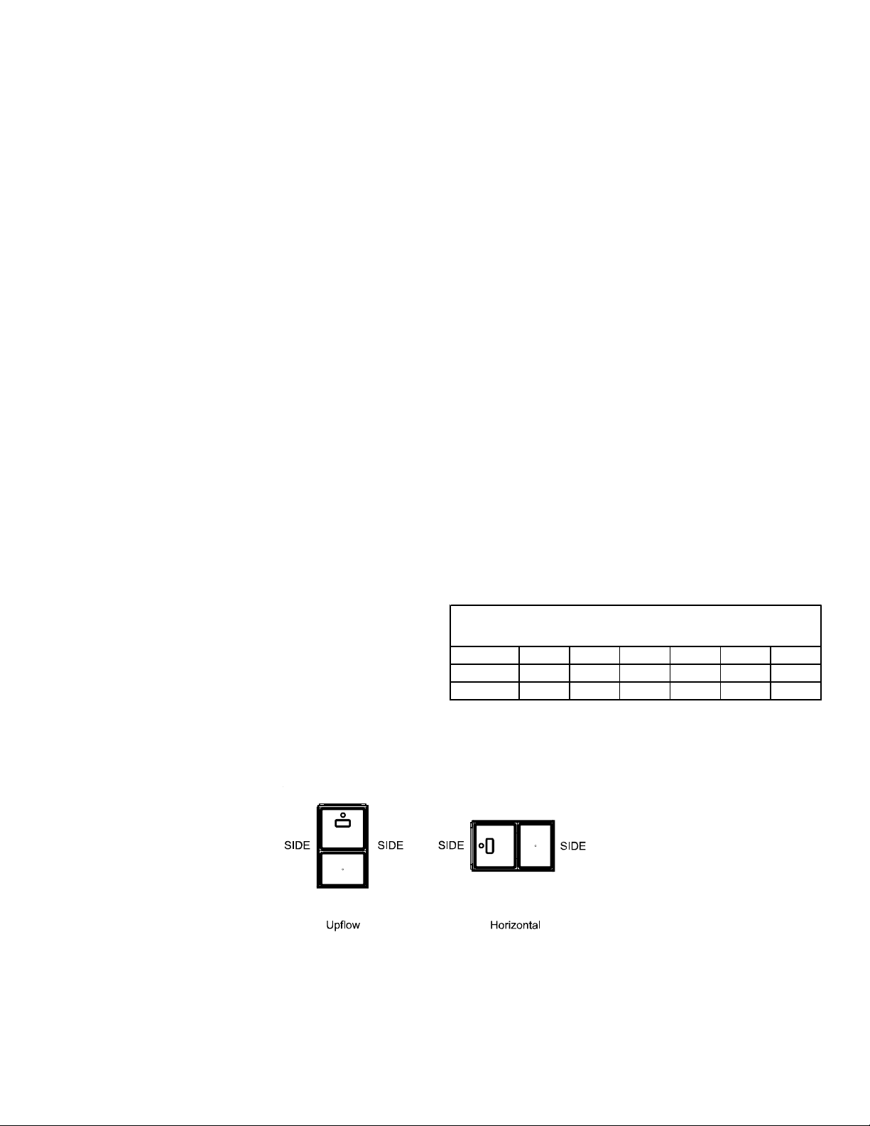
NSTALLATION POSITIONS
Figure 2A Figure 2B Figure 2C
Recommended Installation Positions
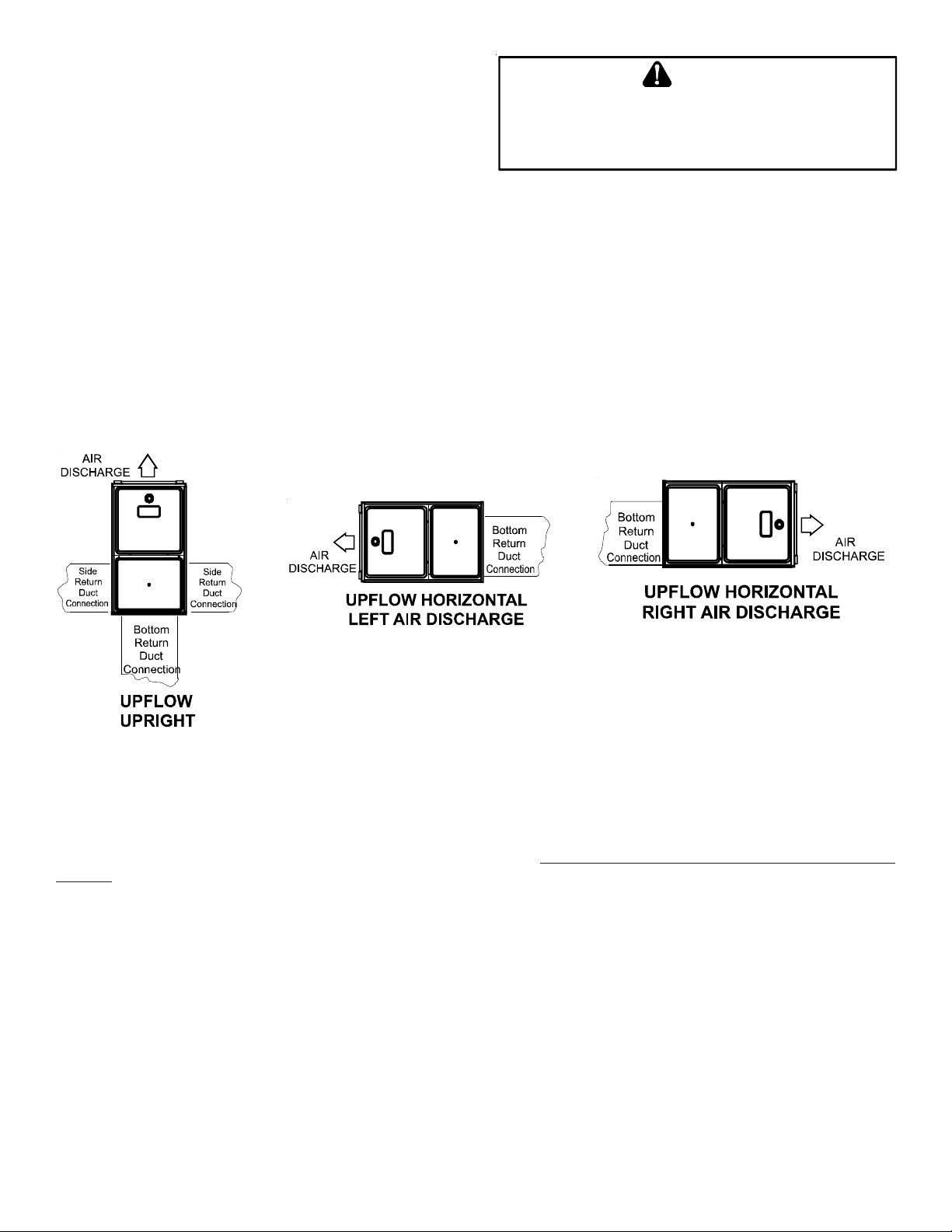
*MEC96 models may be installed upflow or horizontally with left or right side down. Do not install this furnace on its back. For
upright upflow furnaces, return air ductwork may be attached to the side panel(s) and/or basepan. For horizontal upflow
furnaces, return air ductwork must be attached to the basepan. NOTE: Ductwork must never be attached to the back of the
furnace. Contact your distributor for proper airflow requirements and number of required ductwork connections. Refer to
“Recommended Installation Positions” figure for appropriate installation positions, ductwork connections, and resulting airflow
arrangements.
9
Page 10
H
ORIZONTAL APPLICATIONS
& C
ONSIDERATIONS
When installing a furnace horizontally, additional consideration must be given to the following:
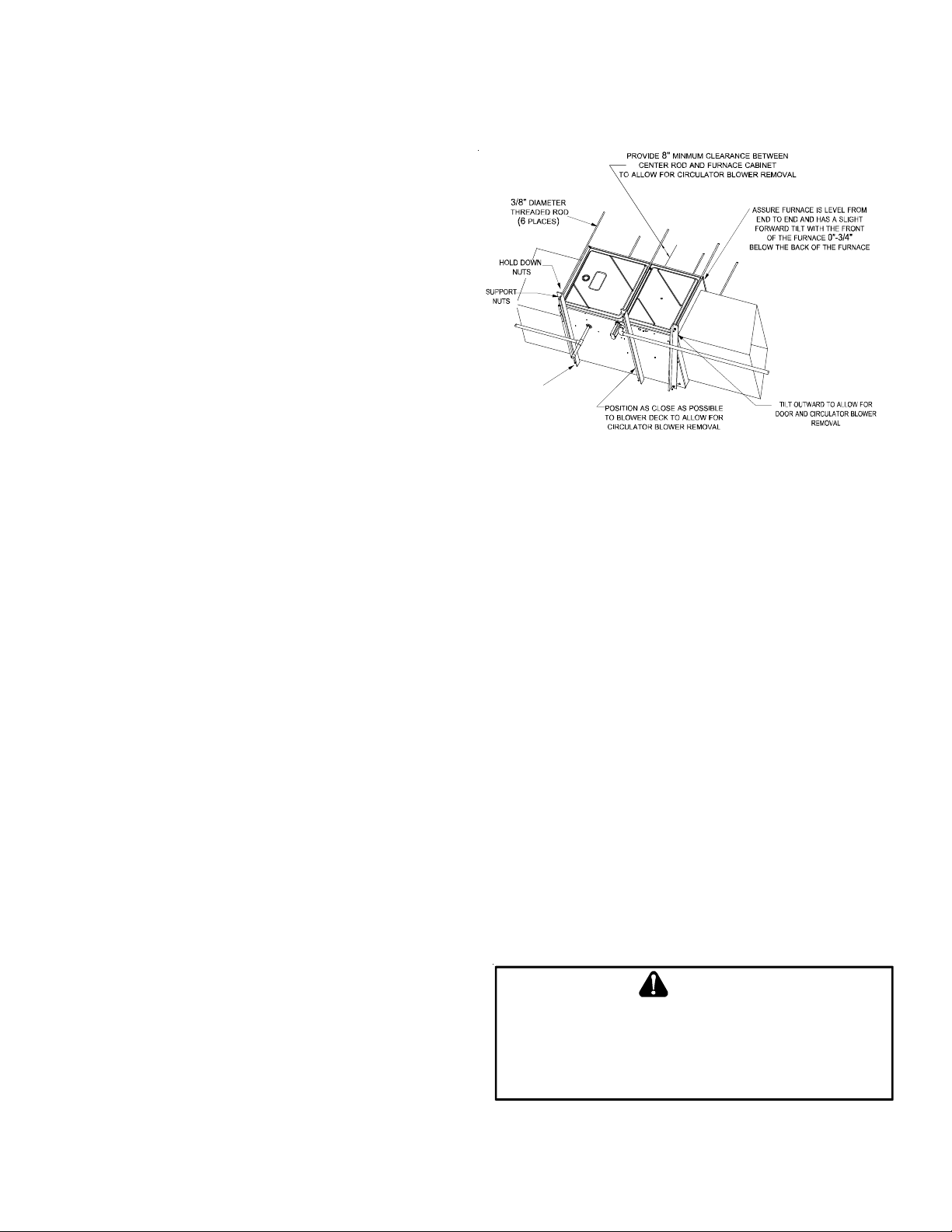
FURNACE S USPENSION
If suspending the furnace from rafters or joists, use 3/8" threaded
rod and 2”x2”x1/8” angle iron as shown in the following diagram. The length of rod will depend on the application and the
clearances necessary.
If the furnace is installed in a crawl space it must be suspended
from the floor joist or supported by a concrete pad. Never install
the furnace on the ground or allow it to be exposed to water.
FRONT COVER PRESSURE SWITCH TUBE LOCATION
When a furnace is installed horizontally with left side down,
the front cover pressure switch tube must be re-locaed to he
lower port of the collector box cover.
1. Remove tubefrom front cover pressure switch and collector
box cover.
2. Remove rubber plug from bottom collector box port and
install on top of collector box port.
3. Locate 24’’ x 1/4’’ tube in bag assembly.
4. Install one end on front cover pressure switch.
5. Route tube to lower port on collector box cover and cut off excess tubing.
2" 2" 3/8"
XX
(3
ANGLE IRON
PLACES
)
Figure 2
DRAIN TRAP AND LINES
In horizontal applications the condensate drain trap is secured to the furnace side panel, suspending it below the furnace. A minimum
clearance of 5.5” below the furnace must be provided for the drain trap. Additionally, the appropriate downward piping slope must be
maintained from the drain trap to the drain location. Refer to Condensate Drain Trap and Lines for further details. If the drain trap and
drain line will be exposed to temperatures near or below freezing, adequate measures must be taken to prevent condensate from
freezing.
HORIZONTAL FURNACE LEVELING
Leveling ensures proper condensate drainage from the heat exchanger. For proper flue pipe drainage, the furnace must be level
lengthwise from end to end. The furnace should have a slight tilt from back to front with the access doors downhill from the
back panel approximately 1/2 to 3/4 inches. The slight tilt allows the heat exchanger condensate, generated in the recuperator
coil, to flow forward to the recuperator coil front cover.
ALTERNATE ELECTRICAL AND GAS LINE CONNECTIONS
This furnace has provisions allowing for electrical and gas line connections through either side panel. In horizontal applications the
connections can be made either through the “top” or “bottom” of the furnace.
DRAIN PAN
A drain pan must be provided if the furnace is installed above a
conditioned area. The drain pan must cover the entire area under
the furnace (and air conditioning coil if applicable).
WARNING
FREEZE PROTECTION
P
Refer to Horizontal Applications and Conditions - Drain Trap and
Lines.
P
ROPANE GAS/HIGH ALTITUDE INSTALLATIONS
OSSIBLE PROPERTY DAMAGE, PERSONAL INJURY OR DEATH MAY
OCCUR IF THE CORRECT CONVERSION KITS ARE NOT INSTALLED
APPROPRIATE KITS MUST BE APPLIED TO ENSURE SAFE AND PROPER
FURNACE OPERATION
QUALIFIED INSTALLER OR SERVICE AGENCY
. ALL
CONVERSIONS MUST BE PERFORMED BY A
.
. THE
This furnace is shipped from the factory configured for natural gas
at standard altitude. Propane gas installations require an orifice and spring change to compensate for the energy content difference
between natural and propane gas.
10
Page 11
High altitude installations may require both
a pressure switch and an orifice/spring
GAS A LTITUDE KIT ORIFICE
change. These changes are necessary to
compensate for the natural reduction in the
density of both the gas fuel and the combustion air at higher altitude. For furnaces being converted to LP gas, it is strongly rec-
NATURAL
0 - 7000
PROPANE
ommended that a LPLP03 kit also be installed. The use of this kit will prevent
the furnace from firing when the LP gas
supply pressure is too low to support
*supports both Honeywell a nd White-Rodgers 2-stage valves
(1) FOR USE WITH ALL MODELS EXCEPT *MEC960302BN**
(2) FOR USE WITH ONLY *MEC960302BN** MODEL
proper combustion.
For installations above 7000 feet, please refer to the furnace
Specification Sheets for required kit(s).
Contact the distributor for a tabular listing of appropriate
MANIFOLD PRESSURE
HIGH STAGE LOW STAGE
NONE 3.5" w.c. 1.9" w.c. NONE
LPM-08* (1) 1.25MM (1)
LPM-30* (2) #57 (2)
#45 (1)
#50 (2)
10.0" w.c. 6.0" w .c. NONE
WARNING
F
AILURE TO FOLLOW THESE INSTRUCTIONS CAN RESULT IN BODILY
INJURY OR DEATH
GIVEN IN THIS SECTION
. C
AREFULLY READ AND FOLLOW ALL INSTRUCTIONS
.
PRESSURE
SWITCH CHAN GE
manufacturer’s kits for propane gas and/or high altitude installations. The indicated kits must be used to insure safe and proper
furnace operation. All conversions must be performed by a qualified installer, or service agency.
V
ENT/FLUE PIPE
& C
OMBUSTION AIR PIPE
A condensing gas furnace achieves its high level of efficiency by
U
PON COMPLETION OF THE FURNACE INSTALLATION, CAREFULLY
INSPECT THE ENTIRE FLUE SYSTEM BOTH INSIDE AND OUTSIDE OF THE
FURNACE TO ASSURE IT IS PROPERLY SEALED
SYSTEM CAN RESULT IN SERIOUS PERSONAL INJURY OR DEATH DUE TO
EXPOSURE TO FLUE PRODUCTS, INCLUDING CARBO N MONOXIDE
WARNING
. L
EAKS IN THE FLUE
.
extracting almost all of the heat from the products of combustion
and cooling them to the point where condensation takes place.
Because of the relatively low flue gas temperature and water condensation requirements, PVC or ABS is typically used as venting
material.
In addition to PVC and ABS pipe and fittings, Innoflue® by Centrotherm Eco Systems and PolyPro® by M&G Duravent are also
approved vent and combustion air materials for installations in the U.S.A. and Canada. Manufacturers Installation instructions for these products must be followed. These products have specific instructions for installing, joining and terminating.
Do not mix materials or components of one manufacturer with materials or components of another manufacturer.
All furnaces are built with 2" vent / intake pipe and connectors. For furnaces requiring installation of 3" pipe, the transition
from 2" to 3" should be done as close to the furnace as practically possible.
This furnace must not be connected to Type B, BW, or L vent or vent connector, and must not be vented into any portion of a factory
built or masonry chimney except when used as a pathway for PVC as described later in this section. Never common vent this appliance
with another appliance or use a vent which is used by a solid fuel appliance. Do not use commercially available “no hub connectors”
other than those shipped with this product.
It is the responsibility of the installer to follow the manufacturers’ recommendations and to verify that all vent/flue piping and
connectors are compatible with furnace flue products. Additionally, it is the responsibility of the installer to ensure that all piping and
connections possess adequate structural integrity and support to prevent flue pipe separation, shifting, or sagging during furnace
operation.
DUAL CERTIFICATION: NON-DIRECT/DIRECT VENT
This furnace is dual certified and may be installed as a non-direct
vent (single pipe) or direct vent (dual pipe) appliance. A non-direct
vent installation requires only a vent/flue pipe, while a direct vent
installation requires both a vent/flue pipe and a combustion air
intake pipe. Refer to the appropriate section for details concerning piping size, length, number of elbows, furnace connections,
and terminations.
TO
AVOID BODILY INJURY, FIRE OR EXPLOSION, SOLVENT CEMENTS
MUST BE KEPT AWAY FROM ALL IGNITION SOURCES (I.E
FLAMES, AND EXCESSIVE HEAT) AS THEY ARE COMBUSTIBLE LIQUIDS
VOID BREATHING CEMENT VAPORS OR CONTACT WITH SKIN AND/OR
A
EYES
.
WARNING
.,
SPARKS, OPEN
.
MATERIALS AND JOINING METHODS
Two-three-inch nominal diameter PVC Schedule 40 pipe meeting ASTM D1785, PVC primer meeting ASTM F656, and PVC
solvent cement meeting ASTM D2564 specifications must be used. Fittings must be DWV type fittings meeting ASTM D2665
and ASTM D3311. Carefully follow the manufacturer’s instructions for cutting, cleaning, and solvent cementing of PVC.
11
Page 12
The use of Schedule 40 PVC cellular core DWV meeting ASTM F891-1 or ABS cellular core (Foam Core) plastic pipe is also
acceptable as a flue/vent and intake pipe material. PVC primer meeting ASTM F656 and PVC solvent cement meeting ASTM
D2564 specifications must be used. Fittings must be DWV type fittings meeting ASTM D2665 and ASTM D3311. Carefully
follow the manufactures instructions for cutting, cleaning and solvent cementing of PVC.
For Canadian Installations; field supplied PVC venting materials must be UL S636 listed.
As an alternative to PVC pipe, primer, solvent cement, and fittings, ABS materials which are in compliance with the following
specifications may be used. Two-or-three-inch ABS Schedule 40 pipe must meet ASTM D1527 and, if used in Canada, must be CSA
listed. Solvent cement for ABS to ABS joints must meet ASTM D2235 and, if used in Canada, must be CSA listed. The solvent cement
for the PVC to ABS transition joint must meet ASTM D3138. Fittings must be DWV type fittings meeting ASTM D2661 and ASTM D3311
and, if used in Canada, must be CSA listed. Carefully follow the manufacturers’ instructions for cutting, cleaning, and solvent
cementing PVC and/or ABS.
All 90° elbows must be medium radius (1/4 bend DWV) or long radius (Long sweep 1/4 bend DWV) types conforming to ASTM D3311.
A medium radius (1/4 bend DWV) elbow measures 3 1/16” minimum from the plane of one opening to the center line of the other
opening for 2” diameter pipe, and 4 9/16” minimum for 3” pipe.
PROPER VENT/FLUE AND COMBUSTION AIR PIPING PRACTICES
Adhere to these instructions to ensure safe and proper furnace performance. The length, diameter, and number of elbows of the vent/
flue pipe and combustion air pipe (when applicable) affects the performance of the furnace and must be carefully sized. All piping
must be installed in accordance with local codes and these instructions.
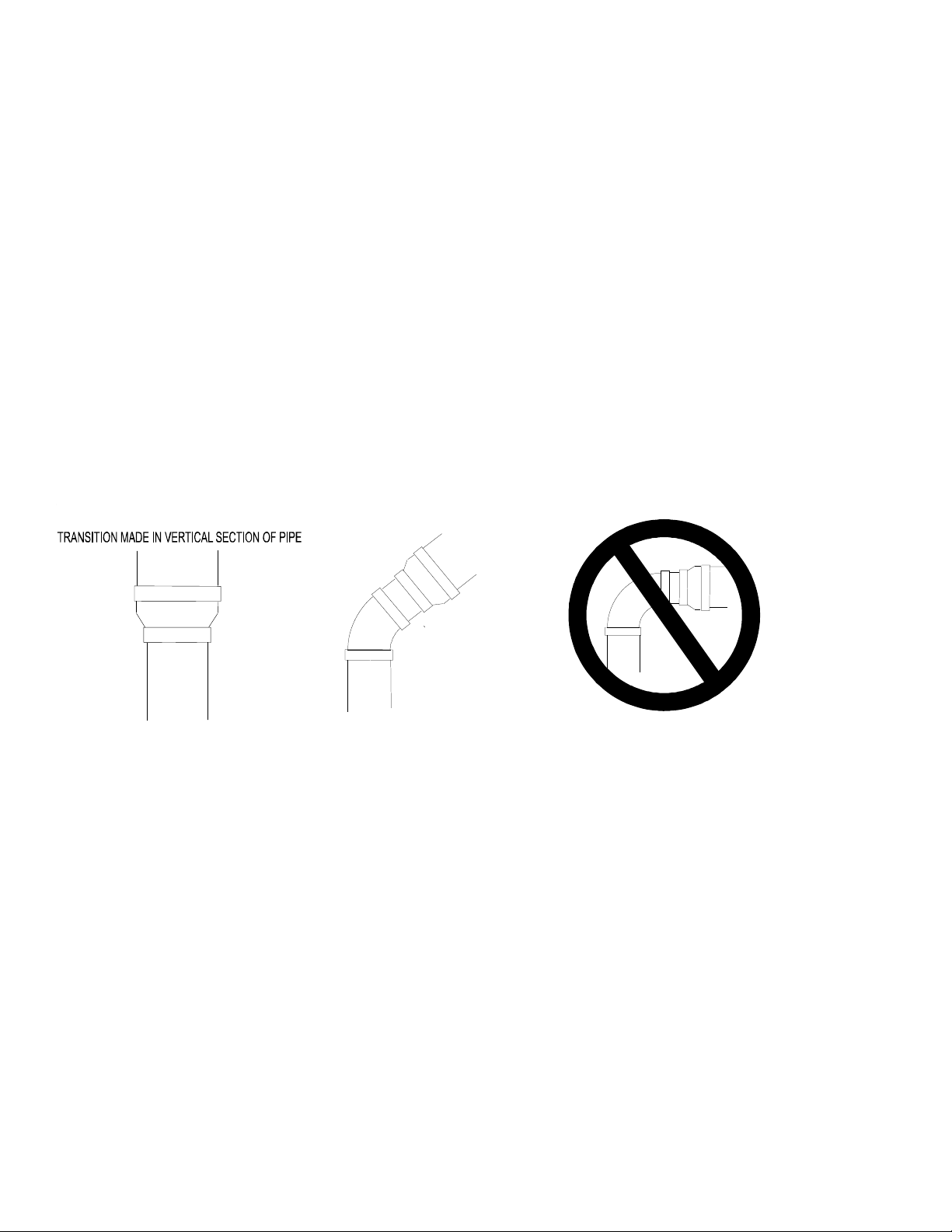
Some models require the use of 3” pipe. Do not transition from a 2” to 3” pipe in a horizontal section of pipe as this may
create a water trap.
PREFERRED
ACCEPTABLE
NO TRANSITION ON
HORIZONTAL PLANE,
THIS CREATES A
WATER TRAP AND
TRANSITION NO LESS
THAN 45 DEGREES TO
HORIZONTAL PLANE TO
AVOID CREATING A WATER
TRAP IN VENT PIPING.
Figure 4 Figure 5 Figure 6
RESTRICTS FLUE
GASES
Piping must be adequately secured and supported to prohibit sagging, joint separation, and/or detachment from the furnace.
Horizontal runs of vent/flue piping must be supported every three to five feet and must maintain a 1/4 inch per foot downward slope,
back towards the furnace, to properly return condensate to the furnace’s drain system. Allowances should be made for minor
expansion and contraction due to temperature variations. For this reason, particular care must be taken to secure piping when a long
run is followed by a short offset of less than 40 inches.
Precautions should be taken to prevent condensate from freezing inside the vent/flue pipe and/or at the vent/flue pipe termination.
All vent/flue piping exposed to freezing temperatures below 35°F for extended periods of time must be insulated with 1/2” thick
closed cell foam. Also all vent/flue piping exposed outdoors in excess of the terminations shown in this manual (or in unheated areas)
must be insulated with 1/2” thick closed cell foam. Inspect piping for leaks prior to installing insulation.
TERMINATION LOCATIONS
NOTE: Refer to Location Requirements and Considerations for combustion air contaminant restrictions.
The following bullets and diagram describe the restrictions concerning the appropriate location of vent/flue pipe and combustion air
intake pipe (when applicable) terminations. Refer to Non-Direct Vent (Single Pipe) Piping and Direct Vent (Dual Pipe) Piping located
in this section for specific details on termination construction.
• All terminations (flue and/or intake) must be located at least 12 inches above ground level or the anticipated snow level.
• Vent terminations (non-direct and direct vent) must terminate at least 3 feet above any forced air inlet located within 10
feet.
NOTE: This provision does not apply to the combustion air intake termination of a direct vent application.
12
Page 13
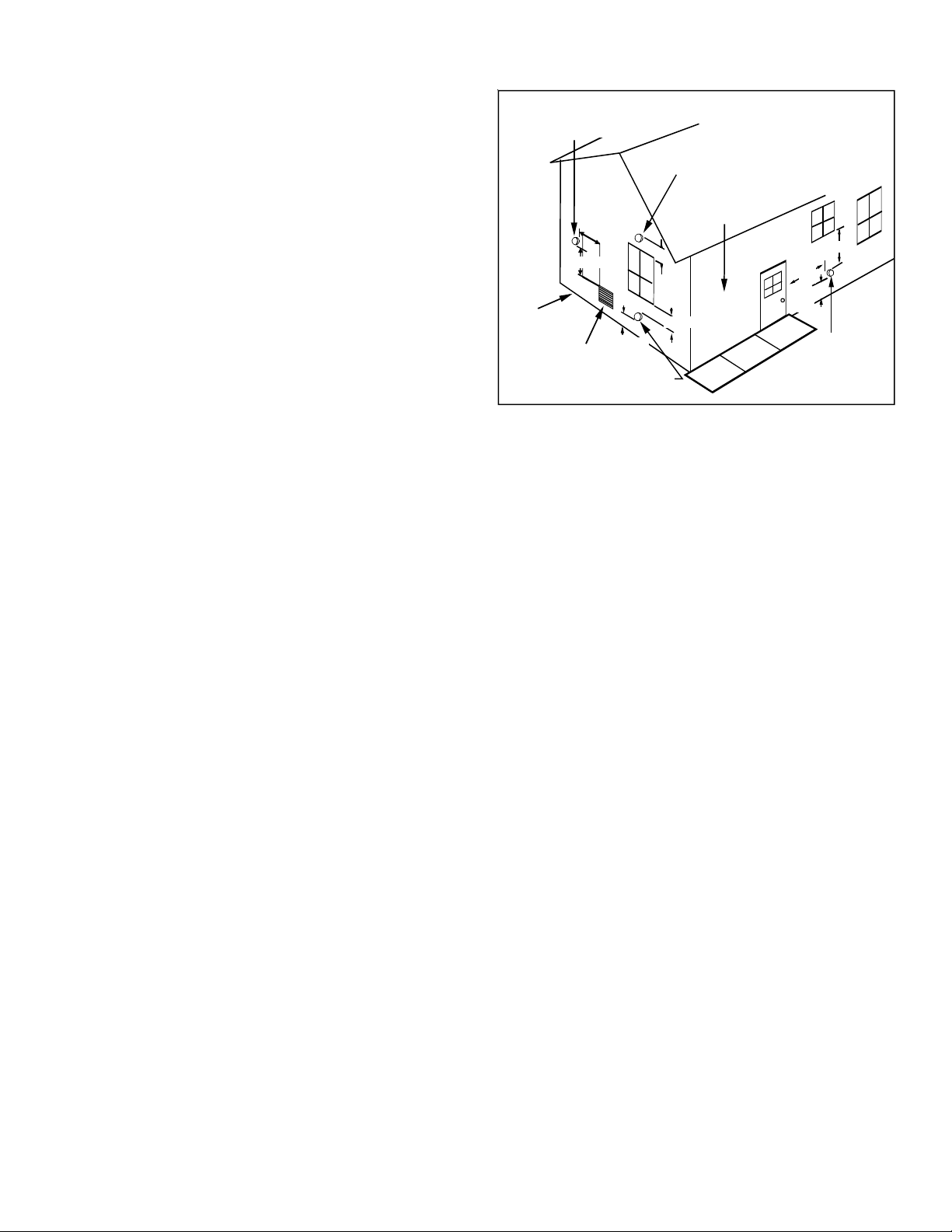
• The vent termination of a non-direct vent application must
terminate at least 4 feet below, 4 feet horizontally from, or 1
foot above any door, window, or gravity air inlet into any
building.
• The vent termination of a direct vent application must
terminate at least 12 inches from any opening through which
Non-Direct Vent
&
Direct Vent
Vent/Flue Terminations
Non-Direct Vent
Vent/Flue Termination
flue gases may enter a building (door, window, or gravity air
inlet).
• The vent termination of vent pipe run vertically through a
roof must terminate at least 12 inches above the roof line (or
the anticipated snow level) and be at least 12 inches from
any vertical wall (including any anticipated snow build up).
• A vent termination shall not terminate over public walkways
or over an area where condensate or vapor could create a
nuisance or hazard or could be detrimental to the operation
of regulators, relief valves, or other equipment.
• The combustion air intake termination of a direct vent
application should not terminate in an area which is frequently
Grade or Highest
Anticipated
Snow Leve l
3' min.
Forced Air
Inlet
<10'
12" min.
Direct Vent
Vent/Flue Termination
12"
12" min.
No Terminations
Above Walkway
4' min.
4'
min.
12"
min.
Non-Direct Vent
Vent/Flue Termination
dusty or dirty.
NOTE: In Canada, the current edition of CAN/CSA B149.1-15
Vent Termination Clearances
Figure 7
takes precedence over the preceding termination description.
CANADIAN VENTING REQUIREMENTS
All installations in Canada must conform to the requirements of CAN/CSA B149.1-15 code. All vent system
components,including primer and cement, must be listed to ULC S636. The certified pipe and fittings should be clearly
marked with the
ULC standard “S636”. The primer and cement used must be of the same manufacturer as the vent system. For Royal
Pipe System 636; use GVS-65 Primer (Purple) and GVS-65 PVC Solvent Cement. For IPEX System 636, use PVC/CPVC
Primer, Purple or clear. Use PVC Solvent Cement (Gray). For Canadian installations, ABS may be used as a combustion air
pipe only. ABS is not an approved vent material in Canada. If ABS is used as a combustion air pipe, it must be CSA
certified. Always follow the manufacturer’s instructions in the use of primer and cement. Do not use primer and cement
around potential sources of ignition. Do not use primer or cement beyond its expiration date. The safe operation, as
defined by ULC S636, of the vent system is based on following these installation instructions, the vent system
manufacturer’s installation instructions, and proper use of primer and cement. It is recommended under this standard,
that the vent system be checked once a year by qualified service personnel. All fire stops and roof flashings used with
this system must be UL listed. Acceptability under CAN/CSA B149.1-15 is dependent upon full compliance with all installation instructions. Consult the authority having jurisdiction (gas inspection authority, municipal building department, fire
department, etc.) before installation to determine the need to obtain a permit. *IPEX System 636™ is a trademark of
IPEX Inc. Carefully follow the pipe manufacturers’ instructions for cutting, cleaning, and solvent cementing PVC and/or
ABS. The vent can be run through an existing unused chimney provided the space between the vent pipe and the chimney
is insulated and closed with a weather-tight, corrosion-resistant flashing.
STANDARD FURNACE CONNECTIONS
It is the responsibility of the installer to ensure that the piping connections to the furnace are secure, airtight, and adequately
supported.
VENT/FLUE P IPE
The vent pipe outlet is sized to accept 2” pipe. Secure vent/flue pipe directly into the furnace fitting with the appropriate glue.
Alternately, a small section of 2" pipe may be glued in the furnace socket and a rubber coupling installed to allow removal for
future service. Combustion Air and Vent piping should be routed in a manner to avoid contact with refrigerant lines, metering
devices, condensate drain lines, etc. If necessary, clearances may be increased by creating an offset using two 45 degree
elbows. This joint can be rotated on the fitting to establish maximum clearance between refrigerant lines, metering devices,
and condensate drain lines, etc. This joint is the equivalent of one 90 deg. elbow when considering elbow count. (Figure 8A)
NOTE: For non-direct vent installations, a minimum of one 90° elbow should be installed on the combustion air intake
coupling to guard against inadvertent blockage.
13
Page 14
DIRECT V ENT I NSTALLATIONS
On upflow units secure the combustion air intake pipe to the air intake coupling by
using a take apart rubber coupling supplied with the furnace or a plastic coupling.
Also, the intake coupling may be inverted to allow the intake pipe to be glued
directly to it. After inverting the coupling, secure it to the furnace top with
screws. On counterflow units secure the combustion air intake pipe to the air intake
coupling using the rubber coupling and worm gear hose clamps provided with the unit.
The counterflow rubber coupling allows service removal of air intake piping internal to
the furnace blower compartment. The combustion air intake pipe can also be secured
directly to the counterflow unit air intake pipe coupling.
COMBUSTION AIR INTAKE OPTION: The RF000142 coupling can be secured directly to the furnace intake coupling if condensation is a concern. If the RF000142
is used on the combustion air inlet, it must be installed with the arrow pointing
up. It should be noted, the combustion air will actually be moving in a direction
opposite of the arrow on the RF000142 coupling. It must have a field supplied,
trapped drain tube free-draining to proper condensate disposal location. A
loop in the drain tube can serve as a trap. The unused RF000142 drain fitting
should be capped. (Figure 8B)
NON-DIRECT V ENT I NSTALLATIONS
A minimum of one 90° elbow should be installed on the combustion air intake “coupling” to guard against inadvertent blockage.
V
E
N
T
45 DEGREE
LONG-SWEEP
ELBOWS
Increased Clearance Configuration
Figure 8A
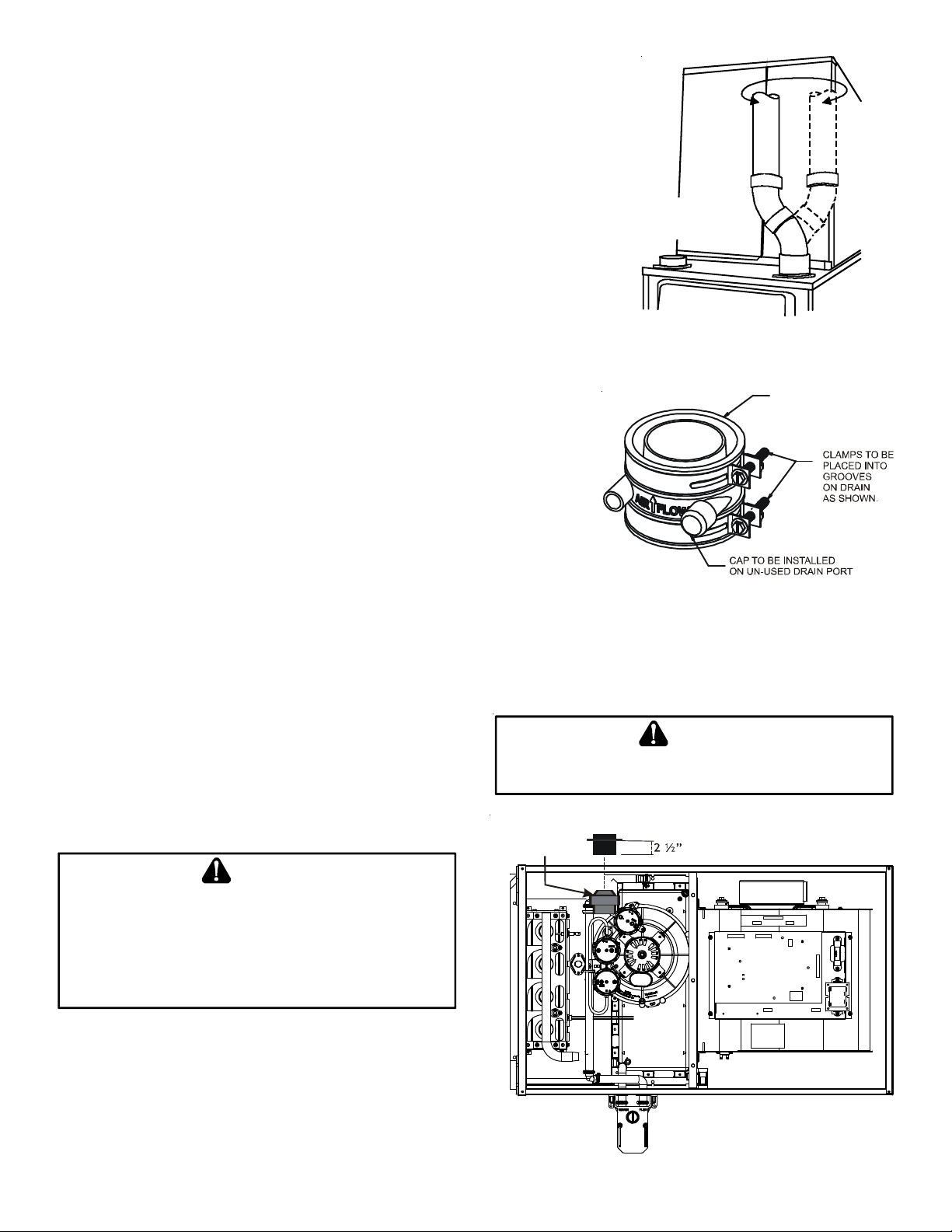
VENT-DRAIN
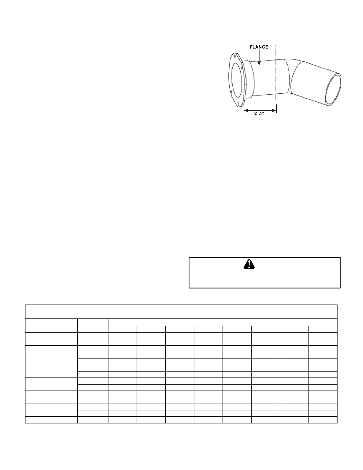
ALTERNATE VENT/FLUE LOCATION
The alternate vent/flue location is the large hole directly in line with the induced
draft blower outlet. To use the alternate vent/flue location refer to the following
steps and the “Alternate Vent/Flue Location” figure.
NOTE: In the horizontal left installation position, a means of condensate collection must be provided to keep vent pipe
condensate from entering the draft inducer housing. If the vent drain elbow is eliminated from the installation, an RF000142
kit must be used.
1. Remove the four screws from the vent pipe flange on top
the furnace.
2. Remove the internal elbow and vent pipe
3. Cut 2 1/2" from the flange .
4. Remove plastic plug in line with the inducer outlet
E
DGES OF SHEET METAL HOLES MAY BE SHARP
PRECAUTION WHEN REMOVING HOLE PLUGS
5. Install cut end of the flanged section and connect to inducer
with rubber coupling supplied with furnace.
6. Install screws removed in step 1 securing flange to cabinet.
R 000142F
Insert flange. Cut 2 ½” long.
WARNING
THE
RUBBER ELBOW IS NOT DESIGNED TO SUPPORT A LOAD
RUBBER ELBOW IS MOUNTED EXTERNALLY TO THE FURNACE CABINET
EXTREME CARE MUST BE TAKEN TO ADEQUATELY SUPPORT FIELD
SUPPLIED VENT/FLUE PIPING, AS DAMAGE CAN RESULT IN LEAKS
CAUSING BODILY INJURY OR DEATH DUE TO EXPOSURE TO FLUE GASES
INCLUDING CARBON MONOXIDE
. W
HEN THE
,
-
,
The RF000142 Coupling
Figure 8B
WARNING
. USE
GLOVES AS A
.
ALTERNATE COMBUSTION AIR PROVISION
(Upflow / Horizontal models only)
When using the alternate venting location, either in a horizontal left side down installation or a vertical installation using down – venting, an alternate combustion air opening can
Figure 9
14
Page 15
be used. A locating dimple is located on the right side of the furnace cabinet. The locating dimple is 1 7/8" measured from
the front edge of the cabinet in line with the knock out. To use the alternate combustion air location:
1. Remove screws and combustion air flange from cabinet.
2. Insert cabinet plug in unused combustion air hole.
3. Drill a pilot hole at the cabinet dimple (size dictated by knockout tool
used).
4. Use a knockout tool to create a 3" diameter hole
5. Install combustion air flange and secure with screws removed in step one.
E
R
E
H
T
U
C
NON-DIRECT VENT (SINGLE PIPE) PIPING
Non-direct vent installations require only a vent/flue pipe. The vent pipe can be run
horizontally with an exit through the side of the building or run vertically with an
exit through the roof of the building. The vent can also be run through an existing
unused chimney; however, it must extend a minimum of 12 inches above the top of
the chimney. The space between the vent pipe and the chimney must be closed with a weather-tight, corrosion-resistant flashing.
Although non-direct vent installations do not require a combustion air intake pipe, a minimum of one 90° elbow should be attached to
the furnace’s combustion air intake if: an upright installation uses the standard intake location, or a horizontal installation uses the
alternate air intake location. This elbow will guard against inadvertent blockage of the air intake.
VENT/FLUE PIPE LENGTHS AND DIAMETERS
For installations at or above 7,000 feet altitude, use 3” venting. Refer to the following table for applicable length, elbows, and
pipe diameter for construction of the vent/flue pipe system of a non-direct vent installation. In addition to the vent/flue pipe, a
single 90° elbow should be secured to the combustion air intake to prevent inadvertent blockage. The tee used in the vent/flue
termination must be included when determining the number of elbows in the piping system.
Vent/Flue Pipe Cuts
Figure 10
1. Maximum allowable limits listed on individual lengths for inlet and flue and NOT a combination.
2. Minimum requirement for each vent pipe if five (5) feet in length and one elbow/tee.
3. Tee used in the vent/flue termination must be included when determining the number of elbows in the piping system.
4. 2 1/2” or 3” diameter pipe can be used in place of 2” diameter
pipe.
5. Increased Clearance Configuration using (2) 45 deg. Long Sweep
elbows should be considered equivalent to one 90 deg. elbow.
BE
SURE NOT TO DAMAGE INTERNAL WIRING OR OTHER COMPONENTS
WHEN REINSTALLING COUPLING AND SCREWS
CAUTION
.
6. One 90° elbow should be secured to the combustion air intake
connection.
*M EC 96 D ir ect V e n t (2 - P ip e) and N o n-Di re ct V e nt (1- P ip e )
M ax imu m A llow ab le L ength of Vent/F lue P ipe
Un it Inpu t (Btu )
*M EC960302BN **
*M EC960402BN **
*M EC960603BN **
*M EC960803BN **
*M EC960804CN **
*M EC961004CN **
*M EC961005CN **
*M EC961205DN ** 3 185 178 171 164 157 150 143 136
Pipe Size
(4)
(in .)
2or 2 1/210095908580757065
3 168 161 154 147 140 133 126 119
2
^
or 2 1/2
2 or 2 1/26055504540353025
2 or 2 1/26055504540353025
2 or 2 1/24540353025201510
2 or 2 1/24540353025201510
^
3 143 136 129 122 115 108 101 94
3 113106999285787164
3 120 113 106 99 92 85 78 71
3 103 96 89 82 75 67 60 53
3 151 144 137 130 123 116 109 102
12345678
50 45 40 35 30 25 20 15
Number of Elbows
(6)
(3) (5 )
For installations at 7,000 or above use 3" venting
^ *M EC960603BN - add 45' of 2" pipe for up flow
15
Page 16
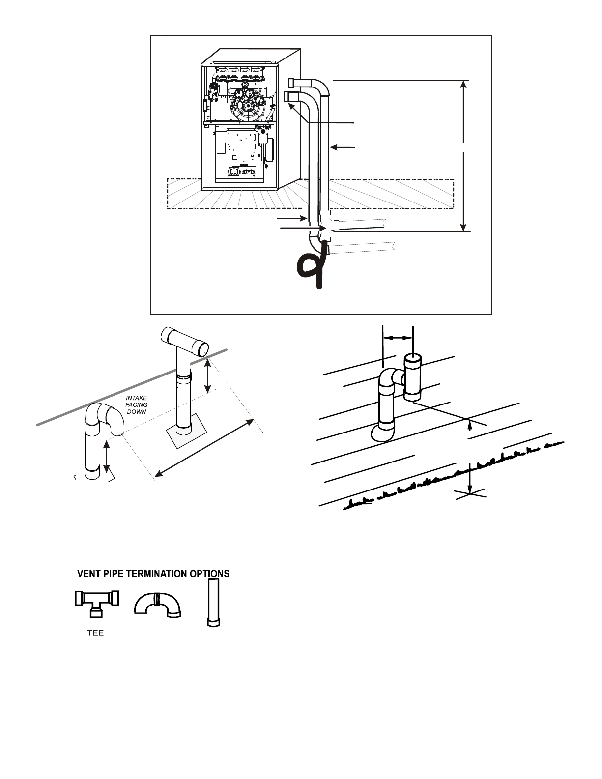
DOWN VENTING UPFLOW MODEL FURNACES ONLY
Use alternate vent
& combination air locations
Figure 11
COMBUSTION AIR INTAKE
(OPTIONAL)
*Not required for
single pipe installation
E
N
I
L
F
O
O
R
Combustion Air Pipe
Field Supplied
Drain Tee on Vent Pipe
e
c
a
p
s
l
w
a
r
C
/
t
n
e
m
e
s
a
B
All piping and fittings must be joined per material manufacturer’s specifications
to prevent separation and flue gas leaks.
Condensate t rapped
to prevent flue gas from escaping
and routed to field supplied
condensate disposal
TEE (OPTIONAL)
12” MIN
HEIGHT DIFFERENCE
BETWEEN
INTAKE AND VENT
Ven t Pip e
r
o
o
l
F
Both Pipes Te rminated
Outside Structure
1/4” per foot min. slope
12" MIN.
VENT/FLUE TEE (
6’ MAX.
OPTIONAL)
or
45° ELBOW
TURNED DOWN or
90° ELBOW TURNED
DOWN
12” MIN TO ROOF OR HIGHEST
ANTICIPATED SNOW LEVEL
Figure 12
ELBOWS
Figure 13
.
X
A
M
”
6
9
STRAIGHT
.
N
I
M
”
3
-
12" M IN. ABOVE
HIGHEST ANTICIPATED
SNOW LEVEL
Horizontal Termination (Single Pipe)
Above Highest Anticipated Snow
Level
Figure 14
16
Page 17

VENT/FLUE PIPE TERMINATIONS
NOTE: If either a 90 degree or 45 degree elbow is used for termination, it must be pointed downward.
The vent/flue pipe may terminate vertically, as through a roof, or horizontally, as through an outside wall.
Vertical vent/flue pipe terminations should be as shown in the following figure. Refer to Vent/Flue Pipe and Combustion Air Pipe -
Termination Locations for details concerning location restrictions. The penetration of the vent through the roof must be sealed tight
with proper flashing such as is used with a plastic plumbing vent.
Horizontal vent/flue pipe terminations should be as shown in the following figure. Refer to Vent/Flue Pipe and Combustion Air Pipe.
To secure the pipe passing through the wall and prohibit damage to piping connections, a coupling should be installed on either side
of the wall and solvent cemented to a length of pipe connecting the two couplings. The length of pipe should be the wall thickness plus
the depth of the socket fittings to be installed on the inside and outside of the wall. The wall penetration should be sealed with
silicone caulking material.
NOTE: Terminate both pipes in the same pressure zone (same side of roof, no major obstacles between pipes, etc.).
DIRECT VENT (DUAL PIPE) PIPING
Direct vent installations require both a combustion air intake and a vent/flue pipe. The pipes may be run horizontally and exit
through the side of the building or run vertically and exit through the roof of the building. The pipes may be run through an existing
unused chimney; however, they must extend a minimum of 12 inches above the top of the chimney. The space between the pipes
and the chimney must be closed with a weather tight, corrosion resistant flashing. Both the combustion air intake and a vent/flue
pipe terminations must be in the same atmospheric pressure zone. Refer to Vent/Flue and Combustion Air Pipe - Termination
Locations or Concentric Vent Termination for specific details on termination construction. For details concerning connection of pipes
to the furnace, refer to the Vent/Flue Pipe and Combustion Pipe - Standard Furnace Connections or Alternate Furnace Connections.
The number of elbows tabulated represents the number of elbows and/or tees in each (Vent/Flue & Combustion Air Intake) pipe.
Elbows and/or tees used in the terminations must be included when determining the number of elbows in the piping systems.
If the combustion air intake pipe is to be installed above a finished ceiling or other area where dripping of condensate will be
objectionable, insulation of the combustion air pipe may be required. Use 1/2” thick closed cell foam insulation such as Armaflex™
or Insultube™ where required.
VENT/FLUE AND COMBUSTION AIR PIPE TERMINATIONS
The vent/flue and combustion air pipes may terminate vertically, as through a roof, or horizontally, as through an outside wall.
Vertical pipe terminations should be as shown in the following figure. Refer to Vent/Flue Pipe and Combustion Pipe - Termination
Locations for details concerning location restrictions. The penetrations through the roof must be sealed tight with proper flashing
such as is used with a plastic plumbing vent.
Vent & Combustion Air Intake Measurements for Standard
Horizontal Terminations (Dual Pipe)
Center to center = 10” min / 24” max. Vertical separation: 0”
- 24”
10”- 24”
Vent termination from wall = 8” min / 12” max.
Combustion air intake from wall = 6” max.
Vent and intake clearance to ground
or anticipated snow level = 12” min.
6” MAX
4” MIN
VENT/INTAKE TERMINATIONS FOR INSTALLATION OF MULTIPLE
DIRECT VENT FURNACES
If more than one direct vent furnace is to be installed vertically
through a common roof top, maintain the same minimum clearances between the exhaust vent and air intake terminations of
adjacent units as with the exhaust vent and air intake terminations of a single unit.
90º OR 45°
ELBOW
12" MIN. TO GRADE OR
HIGHEST ANTICIPATED
SNOW LEVEL
17
Standard Horizontal Terminations (Dual Pipe)
Figure 15
Page 18

If more than one direct vent furnace is to be installed horizontally through a common side wall, maintain the clearances as in the
following figure. Always terminate all exhaust vent outlets at the same elevation and always terminate all air intakes at the same
elevation.
CONCENTRIC VENT TERMINATION
Refer to the directions provided with the Concentric Vent Kit (CVENT) for installation specifications.
SIDE WALL VENT KIT
This kit is to be used with 2” or 3” direct vent systems. The vent kit must terminate outside the structure and may be installed with
the intake and exhaust pipes located side-by-side or with one pipe above the other. These kits are NOT intended for use with single
pipe (non-direct vent) installations.
90°
ELBOWS
90°
ELBOWS
3” - 24”
1 2" MIN. ABOVE
HIGHEST ANTICIPATED
SNOW LEVE L
Combustion Air Intake may also be snorkeled to obtain 12” min ground
clearance.
Alternate Horizontal Vent Termination (Dual Pipe)
Figure 16
Refer to the directions furnished with the Side Wall Vent Kit (p/n
0170K00000S or 0170K00001S) for installation specifications.
C
ONDENSATE DRAIN LINES
& D
RAIN TRAP
A condensing gas furnace achieves its high level of efficiency by
extracting heat from the products of combustion to the point where
condensation takes place. The condensate must be collected in
the furnace drain trap and routed to an appropriate drain location in compliance with local and national codes.
Follow the bullets listed below when installing the drain system.
Refer to the following sections for specific details concerning furnace drain trap installation and drain hose hook ups.
• The drain trap supplied with the furnace must be used.
• The drain trap must be primed at time of installation.
• The drain line between furnace and drain location must
meet local and national codes.
• The drain line between furnace and drain location must
maintain a 1/4 inch per foot downward slope toward the
drain.
• Do not trap the drain line in any other location than at the
drain trap supplied with the furnace.
3”-24” BETWEEN PIPES
12" MIN. ABOVE
HIGHEST AN TICIPATED
SNOW LEVEL
Alternate Vent Termination Above Anticipated Snow Level
(Dual Pipe)
Figure 17
3”MIN
24”MAX
12” MIN SEPARATION
3” MIN
12” MIN TO GRADE OR HIGHEST
ANTICIPATED SNOW LEVEL
Termination of Multiple Direct Vent Furnaces
Figure 18
18
Page 19

• If the drain line is routed through an area which may see
temperatures near or below freezing, precautions must be taken
to prevent condensate from freezing within the drain line.
• If an air conditioning coil is installed with the furnace, a common
Horizontal Installation
drain may be used. An open tee must be installed in the drain
line,
to relieve positive air pressure from the coil’s plenum. This
is necessary to prohibit any interference with the function of the
furnace’s drain trap.
Vertical Installation
GENERAL DRAIN INFORMATION
All furnace models come with a factory installed drain trap. For vertical installations, the trap will remain in the factory position. All
furnace models installed horizontally require the trap to be relocated.
Many drain hoses have a built–in grommet which will provide a cabinet seal when installed. See instructions below for your
model and installation position. NOTE: Both sides of the drain trap must be primed prior to initial furnace start up
Side Wall Vent Kit
Figure 19
FIELD SUPPLIED D RAIN
Drain the furnace and air conditioning coil if applicable, in compliance with code requirements. In horizontal installations, a
field installed rubber coupling will allow the drain trap to be removed for cleaning. The drain trap must be primed before
initial furnace start up. When an air conditioning coil drain is connected to the field supplied furnace drain, it must be vented
with an open tee installed at a height no higher than the bottom of the furnace collector box to prevent air conditioning
condensate from backing up into the furnace if the common drain
became blocked.
UPFLOW MODEL INSTALLED VERTICALLY
The trap and factory installed hoses remain as shipped. The furnace drain may exit either the right or left side of the furnace
cabinet. Both sides of the cabinet have two .875” diameter holes
which can be used interchangeably for drain and low voltage wiring purposes. If a higher drain exit is needed, a .875” diameter
hole may be added in the area shown in Figure 21. Any unused
cabinet opening must be sealed. Do not allow drain hose to sag or
trap water.
Acceptable
area for
drain hole.
Side Cut-Out
12”
3”
Right side shown.
Figure 21
#1
#2
3
#
#11
#5
#8
#10
100 Degree
Elbow
Coupling
#4
#7
#9
6
#
DRAIN EXITING RIGHT SIDE
1. Locate and Install the 45º pipe / hose drain coupling from the
outside of the cabinet (barbed end goes in the cabinet) through
hole in the right side of the cabinet and secure with two field
supplied #8 self-tapping screws (see Figure 22).
19
Figure 20
NOTE: Hoses are model specific
and not all hoses will be shipped with all models.
Page 20

2. Locate the long drain hose #3 and cut at line “A” .
3. Install large end of hose #3 to trap outlet and secure with 1.25"
clamp.
4. Install smaller end of hose #3 on 45º elbow and secure with 1" clamp.
5. Refer to Field Supplied Drain section for instructions on field supplied
/ installed drain on outlet of furnace trap.
DRAIN EXITING LEFT SIDE
1. Install the 45 degree pipe / hose drain coupling from the outside of
Hose #1
Hose #2
the cabinet (barbed end goes in the cabinet) through the hole in
the left side of the cabinet and secure with two field supplied #8
self-tapping screws (see Figure 22).
2. Locate the long drain hose #3 and cut at “B” line for a 17.5" cabinet;
cut at line “C” for a 21" cabinet; do not cut for a “D” width cabinet.
3. Install large end of hose #3 to trap outlet and secure with 1.25"
clamp.
4. Install smaller end of hose #3 on 45º elbow and secure with 1" clamp.
45 degree
barb-pipe
adapter
45 degree
barb-pipe
adapter
5. Refer to Field Supplied Drain section for instructions on field supplied
/ installed drain on outlet of furnace trap.
UPFLOW MODEL INSTALLED HORIZONTALLY WITH RIGHT SIDE DOWN
(SEE FIGURE 23)
Installer selects right or left side drain
and installs this hose accordingly.
Figure 22
Minimum 5 ½” clearance is required for the drain trap beneath the
furnace.
1. Remove the clamps from both ends of the drain hoses.
2. Remove the two screws holding the drain trap to the blower
deck.
3. Remove the trap and two hoses from the blower deck
4. Remove the two plugs from the right side of the cabinet and
install them in the blower deck.
5. (Draining the Vent Elbow) Locate hose #2 (factory installed) and
cut 1" away from the 45 degree bend, discard the 45
degree section. Insert hose #2 from outside the cabinet through
the cabinet drain hole nearest the top. Secure it to the
barbed fitting in the elbow with a red clamp.
Hose #11
Hose #2
6. (Draining the Collector Box) Install the non-grommet end of
hose #11 from outside the cabinet in the bottom drain
Figure 23
hole. Install on collector box and secure with a silver clamp.
7. Use two silver clamps and secure the hoses to drain trap. The trap outlet faces the front of the furnace. Secure the
trap to the cabinet using two screws removed in step 2 by inserting the two screws through the large set of holes in
the top mounting tabs of the trap into the two predrilled holes in the side of the cabinet.
8. Refer to Field Supplied Drain section for instructions on field supplied / installed drain on outlet of furnace trap.
UPFLOW MODEL INSTALLED HORIZONTALLY WITH LEFT SIDE DOWN (SEE FIGURE 24)
Minimum 5 ½” clearance is required for the drain trap beneath the furnace.
*Also see Front Cover Pressure Switch Tube Location on
page 10
1. Remove the clamps from the two drain tubes on the trap.
2. Remove the two screws holding the drain trap to the blower deck.
3. Remove the trap and hoses from the blower deck .
4. Remove the two plugs from the left side of the cabinetand install them in the blower deck.
5. (Draining the Vent Elbow) Locate hose #6. Measuring from the non-grommet end; cut off and discard 1 ½” for
a “D” width cabinet, 5" for a “C” width cabinet, 8 ½” for a “B” width cabinet.
6. Remove the rubber plug from vent – drain elbow side port. Place hose #6 on the vent – drain elbow side port and
secure with a silver clamp .
20
Page 21

7. Unused vent-drain elbow drip leg port must be sealed
to prevent flue gases from escaping. Insert the rubber
plug removed in Step 6 into the unused elbow drain
port; Inserting a blunt tool such as a 3/16" Allen wrench
into the center of the rubber plug will stretch the plug
and allow complete insertion.
8. Locate hose #5 and cut 3" from the non-grommet end.
Discard the section without the grommet.
9. Insert the cut end of tube #5 through the lower cabinet
drain hole.
10. Connect hose #6 & hose #5 using 100º elbow and secure
with two red clamps.
11. (Draining the Collector Box) Remove cap from left side
collector box drain port (bottom in horizontal left position)
and install it on the right side (top) collector box drain port.
12. Install the non-grommet end of hose #11 from outside
the cabinet in the upper drain hole. Install on collector box
and secure with a silver clamp.
13. Use two silver clamps and secure the hoses to drain trap.
The trap outlet faces the front of the furnace. Secure
the trap to the cabinet using two screws removed in
step 2 by inserting the two screws through the large set
of holes in the top mounting tabs of the trap into the
two predrilled holes in the side of the cabinet.
14.Refer to Field Supplied Drain section for instructioins on
field supplied / installed drain on outlet of furnace trap.
WARNING
HIGH VOLTAGE !
TO
AVOID THE RISK OF ELECTRICAL SHOCK, WIRING TO
THE UNIT MUST BE POLARIZED AND GROUNDED
.
WARNING
HIGH VOLTAGE !
TO
AVOID PERSONAL INJURY OR DEATH DUE TO
ELECTRICAL SHOCK, DISCONNECT ELECTRICAL POWER
BEFORE SERVICING OR CHANGING ANY ELECTRICAL
WIRING
.
CAUTION
L
ABEL ALL WIRES PRIOR TO DISCONNECTION WHEN SERVICING
CONTROLS
OPERATION
. W
IRING ERRORS CAN CAUSE IMPROPER AND DANGEROUS
. V
ERIFY PROPER OPERATION AFTER SERVICING
.
UPFLOW MODEL INSTALLED HORIZONTALLY WITH LEFT SIDE
DOWN-ALTERNATE (SEE FIGURE 25)
*Also see Front Cover Pressure Swith Tube Location on page 10
1. (Draining the RF000142 Coupling) Locate hose #2 (factory
installed). Cut off and discard the 45°radius end.
2. Install 90°radius end of hose #2 on RF000142 drain outlet and
secure with a red clamp.
3. Insert coupling in hose #2 and secure with a red clamp.
4. Locate hose #5 and cut 3" from the non-grommet end. Discard the
section without the grommet.
5. Insert the cut end of tube #5 through the lower cabinet drain hole.
6. Insert 100 degree elbow in the cut end of hose #5.
7. Locate hose #6. Using red clamps, connect between the coupling and
100 degree elbow, cutting off excess tubing.
8. (Draining the Collector Box) Remove cap from left side collector box
drain port (bottom in horizontal left position)
and install it on right side (top) collector box drain port.
9. Install the non-grommet end of hose #11 from outside the cabinet in
the upper drain hole. Install on collector box
and secure with a silver clamp.
10. Use two silver clamps and secure the hoses to drain trap. The trap outlet faces the front of the furnace. Secure the
trap to the cabinet using two screws removed in step 2 by
inserting the two screws through the large set of holes in
the top mounting tabs of the trap into the two predrilled
holes in the side of the cabinet.
Hose #6
Hose #5
R 000142F
Hose #11
Figure 24
Insert flange. Cut 2 ½” long.
Figure 25
WARNING
E
DGES OF SHEET METAL HOLES MAY BE SHARP
PRECAUTION WHEN REMOVING HOLE PLUGS
. USE
.
GLOVES AS A
21
Page 22

E
LECTRICAL CONNECTIONS
WARNING
WIRING HARNESS
The wiring harness is an integral part of this furnace. Wires are
color coded for identification purposes. Refer to the wiring dia-
TO
DISCONNECT ELECTRICAL POWER BEFORE INSTALLING OR SERVICING THIS
UNIT
gram for wire routings. If any of the original wire as supplied
with the furnace must be replaced, it must be replaced with
wiring material having a temperature rating of at least 105° C.
Any replacement wiring must be a copper conductor.
115 VOLT LINE CONNECTIONS
Before proceeding with electrical connections, ensure that the
supply voltage, frequency, and phase correspond to that speci-
HIGH VOLTAGE !
TO
AVOID THE RISK OF INJURY, ELECTRICAL SHOCK OR
DEATH, THE FURNACE MUST BE ELECTRICALLY
GROUNDED IN ACCORDANCE WITH LOCAL CODES OR IN
THEIR ABSENCE, WITH THE LATEST EDITION OF THE
ATIONAL ELECTRIC CODE
N
fied on the unit rating plate. Power supply to the furnace must
be NEC Class 1, and must comply with all applicable codes. The
furnace must be electrically grounded in accordance with local
codes or, in their absence, with the latest edition of The National
Electric Code, ANSI NFPA 70 and/or The Canadian Electric Code
CSA C22.1.
Use a separate fused branch electrical circuit containing properly
TO
FURNACE MUST BE ELECTRICALLY GROUNDED IN ACCORDANCE WITH
LOCAL CODES OR, IN THEIR ABSENCE, WITH THE LATEST EDITION OF THE
ATIONAL ELECTRICAL CODE
N
sized wire, and fuse or circuit breaker. The fuse or circuit breaker
must be sized in accordance with the maximum overcurrent protection specified on the unit rating plate. An electrical disconnect must be provided at the furnace location.
W
IRE ROUTING MUST NOT INTERFERE WITH CIRCULATOR BLOWER
OPERATION, FILTER REMOVAL OR ROUTINE MAINTENANCE
Connect hot, neutral, and ground wires as shown in the wiring
diagram located on the unit’s blower door. For direct vent applications,
the cabinet opening to the junction box must be sealed air tight using
either an UL approved bushing such as Heyco Liquid Tight or by applying
non-reactive UL approved sealant to bushing.
PREVENT PERSONAL INJURY OR DEATH DUE TO ELECTRIC SHOCK
.
WARNING
.
WARNING
AVOID THE RISK OF INJURY, ELECTRICAL SHOCK OR DEATH, THE
.
IMPORTANT NOTE
.
Insert flange. Cut 2 ½” long.
R 000142F
,
Line polarity must be observed when making field connections. Line voltage connections can be made through either the right or left side panel.
The furnace is shipped configured for a left side electrical connection with
the junction box located inside the burner compartment. To make electrical connections through the opposite side of the furnace, the junction box
must be relocated to the other side of the burner compartment prior to
making electrical connections. To relocate the junction box, follow the
steps shown below.
NOTE: Wire routing must not to interfere with circulator blower operation,
filter removal, or routine maintenance.
Figure 25
JUNCTION BOX RELOCATION
Line voltage connections can be made through either the right or left side panel. The furnace is shipped configured for a left
side electrical connection. To make electrical connections through the opposite side of the furnace, the junction box must be
relocated to the left side prior to making electrical connections. To relocate the junction box, perform the following steps.
1. Remove the burner compartment door.
2. Remove and save the two screws securing the junction box to the side panel.
3. Relocate junction box and associated plugs and grommets to opposite side panel. Secure with screws removed in step 2.
To ensure proper unit grounding, the ground wire should run from the furnace ground screw located inside the furnace junction box
all the way back to the electrical panel. NOTE: Do not use gas piping as an electrical ground. To confirm proper unit grounding,
turn off the electrical power and perform the following check.
1. Measure resistance between the neutral (white) connection and one of the burners.
2. Resistance should measure 10 ohms or less.
22
Page 23

This furnace is equipped with a blower door interlock switch which
interrupts unit voltage when the blower door is opened for servicing. Do not defeat this switch.
24 VOLT THERMOSTAT WIRING
Low voltage connections can be made through either the right or
left side panel. Thermostat wiring entrance holes are located in
the blower compartment. The following figure shows connections
for a “heat/cool system”.
This furnace is equipped with a 40 VA transformer to facilitate use
with most cooling equipment. Consult the wiring diagram, located on the blower compartment door, for further details of 115
Volt and 24 Volt wiring.
As shipped, the furnace S1-1 switch is OFF; S1-2 switch is ON.
This is the correct position to use a single stage heating
thermostat with auto timing transition to high fire.
SINGLE-STAGE HEATING THERMOSTAT APPLICATION
A single-stage thermostat with only one heating stage may be
used to control this furnace. The application of a single-stage
thermostat offers a timed transition from low to high fire.
The furnace will run on low stage for a fixed period of time
before stepping up to high stage to satisfy the thermostat’s
call for heat. The delay period prior to stepping up can be set
at either a fixed 10 or 20 minute time delay or a load based
variable time between 1 and 12 minutes (AUTO mode). If the
AUTO mode is selected, the control averages the cycle times of
the previous three cycles and uses the average to determine
the time to transition from low stage to high stage.
FOSSIL FUEL APPLICATIONS
This furnace can be used in conjunction with a heat pump in a
fossil fuel application. A fossil fuel application refers to a combined gas furnace and heat pump installation which uses an outdoor temperature sensor to determine the most cost efficient means
of heating (heat pump or gas furnace).
WARNING
HIGH VOLTAGE !
TO
AVOID THE RISK OF ELECTRICAL SHOCK, WIRING TO
THE UNIT MUST BE POLARIZED AND GROUNDED
.
WARNING
HIGH VOLTAGE !
TO
AVOID PERSONAL INJURY OR DEATH DUE TO
ELECTRICAL SHOCK, DISCONNECT ELECTRICAL POWER
BEFORE SERVICING OR CHANGING ANY ELECTRICAL
WIRING
.
CAUTION
L
ABEL ALL WIRES PRIOR TO DISCONNECTION WHEN SERVICING
CONTROLS
OPERATION
. W
IRING ERRORS CAN CAUSE IMPROPER AND DANGEROUS
. V
ERIFY PROPER OPERATION AFTER SERVICING
.
WARNING
E
DGES OF SHEET METAL HOLES MAY BE SHARP
PRECAUTION WHEN REMOVING HOLE PLUGS
Humidifier 1.0 Amp maximum at 120 VAC
Electronic Air Cleaner 1.0 Amp maximum at 120 VAC
. USE
.
GLOVES AS A
WARNING
HIGH VOLTAGE !
TO
AVOID PERSONAL INJURY OR DEATH DUE TO
ELECTRICAL SHOCK, DISCONNECT ELECTRICAL POWER
BEFORE SERVICING OR CHANGING ANY ELECTRICAL
WIRING
.
A heat pump thermostat with three stages of heat is required to
properly use a two-stage furnace in conjunction with a heat pump. Refer to the fossil fuel kit installation instructions for additional
thermostat requirements.
Strictly follow the wiring guidelines in the fossil fuel kit installation instructions. All furnace connections must be made to the furnace
two-stage integrated control module and the “FURNACE” terminal strip
on the fossil fuel control board.
TWINNING
Using the “TWIN” terminals and proper wiring enables two *MEC96
furnaces of the same model and size to be twinned. Twinning allows
simultaneous operation of two furnaces and forces the indoor blower
motors of each furnace to operate synchronously into a common duct
Room
Thermostat
Y2
Y
W
Furnace 1
Ylo
Y
W
Furnace 2
Ylo
Y
W
system. Using the twinning function will require only field installed
wiring with no external kits or parts.
· The staging DIP switches and speed tap DIP switches must be
set the same on both furnaces.
23
W2
W2
R
G
C
R
G
C
W2
R
G
C
Page 24

115 VOLT LINE CONNECTION OF ACCESSORIES (HUMIDIFIER AND
ELECTRONIC AIR CLEANER)
The furnace integrated control module is equipped with line voltage accessory terminals for controlling power to an optional fieldsupplied humidifier and/or electronic air cleaner.
The accessory load specifications are noted in the chart at right:
CAUTION
TO
PREVENT UNRELIABLE OPERATION OR EQUIPMENT DAMAGE, THE
INLET GAS SUPPLY PRESSURE MUST BE AS SPECIFIED ON THE UNIT
RATING PLATE WITH ALL OTHER HOUSEHOLD GAS FIRED APPLIANCES
OPERATING
.
Y C
Remote Conden sing Unit
(Single-Stage Cooling)
R
Furnace
R
Integrated
Control
Module
Y C
Remote Condensing Unit
(Single-Stage Cooling)
R
Furnace
R
Integrated
Control
Module
Y2
Y
Y2
Remote Condensing Unit
(Two-S tage Cooling)
W1 W2
W1 W2
Furnace
Integrated
Control
Module
Thermostat - Single -Stage Heating
with Single-Stage Cooling
NOTE: To apply a single-stage Heating
Thermostat, the thermostat selector
switch on the Integrated Control Module
must be set on single-stage.
Thermostat - Two-Stage Heating
with Single-Stage Cooling
Figure 27
Thermostat - Two-Stage Heating with
Two-Stage Cooling
Thermostat Wiring Diagrams
Figure 28
Figure 26
Turn OFF power to the furnace before installing any accessories. Follow the humidifier or air cleaner manufacturers’ instructions for
locating, mounting, grounding, and controlling these accessories. Accessory wiring connections are to be made through the 1/4"
quick connect terminals provided on the furnace integrated control module. The humidifier and electronic air cleaner hot terminals
are identified as HUM and EAC. The humidifier and electronic air cleaner neutral terminals are identified as NEUTRAL. All field wiring
must conform to applicable codes. Connections should be made as shown.
If it is necessary for the installer to supply additional line voltage wiring to the inside of the furnace, the wiring must conform to all
local codes, and have a minimum temperature rating of 105°C. All line voltage wire splices must be made inside the furnace junction
box.
S1
DIP
Switch
Numbe r
1, 2
3, 4
Purp os e
Heat
Staging /
Dela y
Blower
Hea t Off
Del ay
Function
Auto 1 OFF* 2 ON*
10 Minutes 1 ON 2 OFF
20 Min utes 1 ON 2 ON
2 Stage 1 OFF 2 OFF
90 Se cond s 3 OFF 4 OFF
120 Se cond s 3 OFF 4 ON
150 Se cond s 3 ON* 4 OFF *
180 Se cond s 3 ON* 4 ON
The integrated control module humidifier terminal (HUM) is energized with 115 volts whenever the induced draft blower is energized. The integrated control module electronic air cleaner terminal
(EAC) is energized with 115 volts whenever the circulator blower is
energized. This terminal can also be used to provide 115 volt
power to a humidifier transformer. The remaining primary transformer wire would be connected to the Line N on the control
board.
GAS S
UPPLY AND PIPING
DIP
Switch
Group
* = Fa ctory Posi tion
The furnace rating plate includes the approved furnace gas input
rating and gas types. The furnace must be equipped to operate on the type of gas applied. This includes any conversion kits required
for alternate fuels and/or high altitude.
Inlet gas supply pressures must be maintained within the ranges specified in the adjacent table. The supply pressure must be
constant and available with all other household gas fired appliances operating. The minimum gas supply pressure must be maintained
to prevent unreliable ignition. The maximum must not be exceeded to prevent unit overfiring.
24
Page 25

HIGH ALTITUDE DERATE
When this furnace is installed at high altitude, the appropriate High Altitude orifice kit must be applied. This is required due to the
natural reduction in the density of both the gas fuel and combustion air as altitude increases. The kit will provide the proper design
certified input rate within the specified altitude range.
High altitude kits are purchased according to the installation altitude and usage of either natural or propane gas. Consult the furnace
Specification Sheet for appropriate kits.
Do not derate the furnace by adjusting the manifold pressure to a lower pressure than specified on the furnace rating plate. The
combination of the lower air density and a lower manifold pressure will prohibit the burner orifice from drawing the proper amount of
air into the burner. This may cause incomplete combustion, flashback, and possible yellow tipping.
In some areas the gas supplier may artificially derate the gas in an effort to compensate for the effects of altitude. If the gas is
artificially derated, the appropriate orifice size must be determined based upon the BTU/ft3 content of the derated gas and the
altitude. Refer to the National Fuel Gas Code, NFPA 54/ANSI Z223.1, and information provided by the gas supplier to determine the
proper orifice size.
A different pressure switch may be required at high altitude re-
3
gardless of the BTU/ft
content of the fuel used. Consult the
furnace Specification Sheet for pressure switch.
Humidifier 1.0 Amp maximum at 120 VAC
Electronic Air Cleaner 1.0 Amp maximum at 120 VAC
PROPANE GAS CONVERSION
This unit is configured for natural gas, but may be converted for
use with L.P. gas. Refer to the section on PROPANE GAS/HIGH
ALTITUDE INSTALLATIONS for L.P. kit selection.
Consult the furnace Specification Sheet for a listing of appropriate kits. The indicated kits must be used to insure safe and
proper furnace operation. All conversions must be performed by a
qualified installer, or service agency.
GAS VALVE
This unit is equipped with a 24 volt gas valve controlled during furnace operation by the
integrated control module. As shipped, the valve is configured for natural gas. The valve
is field convertible for use with propane gas by replacing the regulator spring with a propane
gas spring from an appropriate manufacturer’s propane gas conversion kit. Taps for measuring the gas supply pressure and manifold pressure are provided on the valve.
The gas valve has a manual ON/OFF control located on the valve itself. This control may be
set only to the “ON” or “OFF” position. Refer to the lighting instructions label or Startup
Procedure & Adjustment for use of this control during start up and shut down periods.
HIGH VOLTAGE !
TO
AVOID PERSONAL INJURY OR DEATH DUE TO
ELECTRICAL SHOCK, DISCONNECT ELECTRICAL POWER
BEFORE SERVICING OR CHANGING ANY ELECTRICAL
WIRING
.
WARNING
GAS PIPING CONNECTIONS
The gas piping supplying the furnace must be properly sized based on the gas flow required,
specific gravity of the gas, and length of the run. The gas line installation must comply with
local codes, or in their absence, with the latest edition of the National Fuel Gas Code, NFPA
54/ANSI Z223.1.
To connect the furnace to the building’s gas piping, the installer
must supply a ground joint union, drip leg, manual shutoff valve,
and line and fittings to connect to gas valve. In some cases, the
installer may also need to supply a transition piece from 1/2" pipe
to a larger pipe size.
The following stipulations apply when connecting gas piping. Refer
to Gas Piping Connections figure for typical gas line connections to
the furnace.
• Gas piping must be supported external to the furnace cabinet
so that the weight of the gas line does not distort the burner
rack, manifold or gas valve.
TO
AVOID POSSIBLE UNSATISFACTORY OPERATION OF EQUIPMENT
DAMAGE DUE TO UNDERFIRING OR EQUIPMENT, USE THE PROPER SIZE
OF NATURAL/PROPANE GAS PIPING NEEDED WHEN RUNNING PIPE FROM
THE METER/TANK TO THE FURNACE
INLET GAS SUPPLY PRESSURE
Natural Gas Minimum: 4.5" w.c. Maximum: 10.0" w.c.
Propane Gas Minimum: 11.0" w.c. Maximum: 13.0" w.c.
25
Accessories - Accessories Wiring
Figure 29
WARNING
.
Page 26

• Use black iron or steel pipe and fittings for building piping.
Where possible, use new pipe that is properly chamfered,
reamed, and free of burrs and chips. If old pipe is used, be
sure it is clean and free of rust, scale, burrs, chips, and old
pipe joint compound.
• Use pipe joint compound on male threads ONLY. Always use
pipe joint compound (pipe dope) that is APPROVED FOR ALL
P
OSSIBLE PROPERTY DAMAGE, PERSONAL INJURY OR DEATH MAY
OCCUR IF THE CORRECT CONVERSION KITS ARE NOT INSTALLED
APPROPRIATE KITS MUST BE APPLIED TO ENSURE SAFE AND PROPER
FURNACE OPERATION
QUALIFIED INSTALLER OR SERVICE AGENCY
. ALL
WARNING
. THE
CONVERSIONS MUST BE PERFORMED BY A
.
GASSES. DO NOT apply compound to the first two threads.
• Use ground joint unions.
• Install a drip leg to trap dirt and moisture before it can enter the gas valve. The drip leg must be a minimum of three inches
long.
• Install a 1/8" NPT pipe plug fitting, accessible for test gage connection, immediately upstream of the gas supply connection to
the furnace.
• Always use a back-up wrench when making the connection to the gas valve to keep it from turning. The orientation of the gas
valve on the manifold must be maintained as shipped from the factory. Maximum torque for the gas valve connection is 375
in-lbs; excessive over-tightening may damage the gas valve.
• Install a manual shutoff valve between the gas meter and unit within six feet of the unit. If a union is installed, the union must
be downstream of the manual shutoff valve, between the shutoff valve and the furnace.
• Tighten all joints securely.
• Connect the furnace to the building piping by one of the following methods:
– Rigid metallic pipe and fittings.
– Semi-rigid metallic tubing and metallic fittings. Aluminum alloy tubing must not be used in exterior locations. In order to
seal the grommet cabinet penetration, rigid pipe must be used to reach the outside of the cabinet. A semi-rigid connector
to the gas piping may be used from there.
• Use listed gas appliance connectors in accordance with their instructions. Connectors must be fully in the same room as the
furnace.
• Protect connectors and semirigid tubing against physical and thermal damage when installed. Ensure aluminum-alloy tubing
and connectors are coated to protect against external corrosion when in contact with masonry, plaster, or insulation, or
subjected to repeated wetting by liquids such as water (except rain water), detergents, or sewage.
The gas piping may enter the left or right side of the furnace
cabinet. The installer must supply rigid pipe long enough to reach
the outside of the cabinet to seal the grommet cabinet penetration.
A semi-rigid connector to the gas piping can be used outside the
cabinet per local codes. 1/2” NPT pipe and fittings are required.
For models with an “L” shaped manifold, a 4 1/2” long nipple is
required. For models with a hook shaped manifold, a 2” long
nipple is required.
A semi-rigid connector to the gas piping can be used outside
the cabinet per local codes. From the elbow, the length of pipe
and the fittings required will vary by the side chosen, location
of union and cabinet width. The union may be placed inside or
outside of the cabinet.
GAS PIPING CHECKS
Before placing unit in operation, leak test the unit and gas connections.
Length of Nominal Black Pipe Size
Pipe in Feet 1/2" 3/4" 1" 1 1/4" 1 1/2"
10 132 278 520 1050 1600
20 92 190 350 730 1100
30 73 152 285 590 980
40 63 130 245 500 760
50 56 115 215 440 670
60 50 105 195 400 610
70 46 96 180 370 560
80 43 90 170 350 530
90 40 84 160 320 490
100 38 79 150 305 460
(Pressure 0.5 psig or less and pressure drop of 0.3" W.C.; Based on
0.60 Specific Gravity Gas)
BTUH Furnace Input
CFH =
Heating Value of Gas (BTU/Cubic Foot)
Natural Gas Capacity of Pipe
In Cubic Feet of Gas Per Hour (CFH)
Check for leaks using an approved chloride-free soap and water solution, an electronic combustible gas detector, or other approved
testing methods.
NOTE: Never exceed specified pressures for testing. Higher pressure may damage the gas valve and cause subsequent overfiring,
resulting in heat exchanger failure.
26
Page 27

Disconnect this unit and shutoff valve from the gas supply piping system before pressure testing the supply piping system with
pressures in excess of 1/2 psig (3.48 kPa).
Isolate this unit from the gas supply piping system by closing its external manual gas shutoff valve before pressure testing supply
piping system with test pressures equal to or less than 1/2 psig (3.48 kPA).
PROPANE GAS TANKS AND PIPING
A gas detecting warning system is the only reliable way to detect a propane gas leak. Rust can reduce the level of odorant in propane
gas. Do not rely on your sense of smell. Contact a local propane gas supplier about installing a gas detecting warning system. If the
presence of gas is suspected, follow the instructions listed in the Safety Considerations section of this manual.
All propane gas equipment must conform to the safety standards of the National Board of Fire Underwriters, NBFU Manual 58.
For satisfactory operation, propane gas pressure must be 10” WC at the furnace manifold with all gas appliances in operation.
Maintaining proper gas pressure depends on three main factors:
1. Vaporization rate, depending on temperature of the liquid,
and “wetted surface” area of the container or containers.
2. Proper pressure regulation. (Two-stage regulation is
N
recommended for both cost and efficiency).
3. Pressure drop in lines between regulators, and between
second stage regulator and the appliance. Pipe size will
EVER ALLOW THE PRODUCTS OF COMBUSTION, INCLUDING CARBO N
MONOXIDE, TO ENTER THE RETURN DUCT WORK OR CIRCULATION AIR
SUPPLY
.
depend on length of pipe run and total load of all appliances.
Complete information regarding tank sizing for vaporization, recommended regulator settings, and pipe sizing is available from most
regulator manufacturers and propane gas suppliers.
WARNING
Since propane gas will quickly dissolve white lead and most standard commercial compounds, special pipe dope must be used.
Always use a pipe thread sealant approved for all gases.
Alternate
Gas Line
Location
Manifold
Burners
Manual Shut Off Valve
(upstream from
ground joint
pipe union)
Refer to the this illustration for typical propane gas installations
and piping.
C
IRCULATING AIR
& F
DUCT WORK - AIR FLOW
ILTERS
Gas Valve
*Ground
Joint
Pip e
Union
*Ground
Joint
Pip e
Union
Drip Leg
Duct systems and register sizes must be properly designed for
the CFM and external static pressure rating of the furnace. Design the ductwork in accordance with the recommended methods of “Air Conditioning Contractors of America” Manual D.
Grommet
in Standard
Gas Line
Hole
Install the duct system in accordance with Standards of the National Board of Fire Underwriters for the Installation of Air Conditioning, Warm Air Heating and Ventilating Systems. Pamphlets
No. 90A and 90B.
A closed return duct system must be used, with the return duct
connected to the furnace. NOTE: Ductwork must never be at-
*NOTE: Union may be inside furnace cabinet where allowed by local codes.
UPFLOW
Figure 30
Gas Connections
tached to the back of the furnace. For upflow installations requiring 1800 CFM or more, use either two side returns or bottom
return or a combination of side /bottom. Flexible joints may be used for supply and return connections to reduce noise transmission.
To prevent the blower from interfering with combustion air or draft when a central return is used, a connecting duct must be installed
between the unit and the utility room wall. Never use a room, closet, or alcove as a return air chamber.
CHECKING DUCT STATIC
Refer to your furnace rating plate for the maximum ESP (external duct static) rating.
Total external static refers to everything external to the furnace cabinet. Cooling coils, filters, ducts, grilles, registers
must all be considered when reading your total external static
pressure. The supply duct pressure must be read between the
TO
AVOID THE POSSIBILITY OF EXPLOSION OR FIRE, NEVER USE A MATCH
OR OPEN FLAME TO TEST FOR LEAKS
27
WARNING
.
Page 28

furnace and the cooling coil. This reading is usually taken by removing the “A” shaped block off plate from the end on the
coil; drilling a test hole in it and reinstalling the block off plate. Take a duct static reading at the test hole. Tape up the test
hole after your test is complete. The negative pressure must be read between the filter and the furnace blower.
Too much external static pressure will result in insufficient air
that can cause excessive temperature rise. This can cause limit
switch tripping and heat exchanger failure.
To determine total external duct static pressure, proceed as
follows;
1. With clean filters in the furnace, use a draft gauge (inclined manometer) to measure the static pressure of the
return duct at the inlet of the furnace. (Negative Pressure)
2. Measure the static pressure of the supply duct. (Positive
Pressure)
IF
THE GAS FURNACE IS INSTALLED IN A BASEMENT, AN EXCAVATED
AREA OR CONFINED SPACE, IT IS STRONGLY RECOMMENDED TO
CONTACT A PROPANE SUPPLIER TO INSTALL A GAS DETECTING WARNING
DEVICE IN CASE OF A GAS LEAK
S
INCE PROPANE GAS IS HEAVIER THAN AIR, ANY LEAKING GAS CAN
•
SETTLE IN ANY LOW AREAS OR CONFINED SPACES
•
ROPANE GAS ODORANT MAY FADE, MAKING THE GAS UNDETECTABLE
P
EXCEPT WITH A WARNING DEVICE
WARNING
.
.
.
3. The difference between the two numbers is .4” w.c.
Example:
static reading from return duct = -.1" w.c.
First Stage
Regulator
5 to 15 PSIG
(20 PSIG M ax.)
Continuous
11" W.C.
static reading from supply duct = .3" w.c.
total external static pressure on this system = .4" w.c.
200 PSIG
Maximum
Second Stage
Regulator
NOTE: Both readings may be taken simultaneously and read directly
on the manometer if so desired. If an air conditioner coil or Electronic Air Cleaner is used in conjunction with the furnace, the readings must also include theses components, as shown in the following
drawing.
4. Consult proper tables for the quantity of air.
Propane Gas Installation (Typ.)
Figure 31
If the total external static pressure exceeds the maximum listed on
the furnace rating plate, check for closed dampers, registers, undersized and/or oversized poorly laid out duct work.
The temperature rise of the furnace must be within the temperature rise range listed on the furnace rating plate.
BOTTOM RETURN AIR OPENING [UPFLOW MODELS]
The bottom return air opening on upflow models utilizes a “lance and cut” method
to remove sheet metal from the duct opening in the base pan. To remove, simply
press out the lanced sections by hand to expose the metal strips retaining the
sheet metal over the duct opening. Using tin snips, cut the metal strips and
remove the sheet metal covering the duct opening. In the corners of the opening, cut the sheet metal along the scribe lines to free the duct flanges. Using the
scribe line along the duct flange as a guide, unfold the duct flanges around the
perimeter of the opening using a pair of seamer pliers or seamer tongs.
NOTE: Airflow area will be reduced by approximately 18% if duct flanges are not
unfolded. This could cause performance issues and noise issues.
When the furnace is used in connection with a cooling unit, the furnace should be
installed in parallel with or on the upstream side of the cooling unit to avoid
condensation in the heating element. With a parallel flow arrangement, the
dampers or other means used to control the flow of air must be adequate to
prevent chilled air from entering the furnace and, if manually operated, must be
equipped with means to prevent operation of either unit unless the damper is in
the full heat or cool position.
When the furnace is installed without a cooling coil, it is recommended that a
removable access panel be provided in the outlet air duct. This opening shall be
accessible when the furnace is installed and shall be of such a size that the heat
Checking Static Pressure
(80% Furnace Shown, 90% Similar)
Figure 32
exchanger can be viewed for visual light inspection or such that a sampling probe
can be inserted into the airstream. The access panel must be made to prevent air leaks when the furnace is in operation.
28
Page 29

When the furnace is heating, the temperature of the return air entering the furnace must be between 55°F and 100°F.
FILTERS - READ THIS SECTION BEFORE INSTALLING THE RETURN AIR DUCT WORK
Filters must be used with this furnace. Discuss filter maintenance with the building owner. Filters do not ship with this furnace, but
must be provided, sized and installed externally by the installer. Filters must comply with UL900 or CAN/ULCS111 standards. Damage
or repairs due to the installation of the furnace without filters is not covered under the warranty.
On upflow units, guide dimples locate the side return cutout locations. Use a straight edge to scribe lines connecting the dimples. Cut
out the opening on these lines. NOTE: An undersized opening will cause reduced airflow.
Refer to the following table to determine filter area requirements.
Change filters before occupants take ownership of a new home!
UPRIGHT INSTALLATIONS
Depending on the installation and/or customer preference, differing filter arrangements can be applied. Filters can be installed in the
central return register or a side panel external filter rack kit (upflows). As an alternative a media air filter or electronic air cleaner can
be used as the requested filter. Consider installing an air cleaner with deep-pleated media filter at the time of furnace
installation. A deep-pleated filter with a MERV rating of 8 (minimum) will often provide better filtration to protect equipment and the air distribution system than a standard 1" filter and often has lower static pressure loss than a 1" filter. Also
a deep-pleated filter will typically require less frequent replacement intervals. Avoid using highly restrictive 1" filters which
produce static pressure loss greater than .25" W.C. In some installations the minimum filter size required will not lend itself
to a filter installation on the side of the furnace. The installation of a centrally installed air cleaner cabinet or a return duct
filter installation may offer more practicality.
Clean Comfort™ brand MERV 11 air cleaners have 5¼” media
filters and are available in the following configurations.
Consult your distributor for information on our complete line
of IAQ Clean Comfort™ products.
The figure at right shows possible filter locations.
E
DGES OF SHEET METAL HOLES MAY BE SHARP
PRECAUTION WHEN REMOVING SHEET METAL FROM RETURN AIR
OPENINGS
.
HORIZONTAL INSTALLATIONS
Filters must be installed in either the central return register or in the return air duct work.
S
TARTUP PROCEDURE
& A
DJUSTMENT
Furnace must have a 115 VAC power supply properly connected and
grounded. Proper polarity must be maintained for correct operation. In
addition to the following start-up and adjustment items, refer to further
CUT USING TI N SNIP S
information in Operational Checks section.
DRAIN TRAP PRIMING
The drain trap MUST be primed prior to furnace startup. To prime, fill
both sides of the drain trap with water. This ensures proper furnace
drainage upon startup and prohibits the possibility of flue gases escaping
through the drain system.
FURNACE OPERATION
Purge gas lines of air prior to startup. Be sure not purge lines into an
enclosed burner compartment.
CUT FOUR CORNERS
AFTER REMOVING S HEET
METAL
WARNING
. USE
GLOVES AS A
PRESS OUT BY HAND
SCRIBE LINES OUTLINING
DUCT FLANGES
Check for leaks using an approved chloride-free soap and water solution,
an electronic combustible gas detector, or other approved method. Verify
that all required kits (propane gas, high altitude, etc.) have been appropriately installed.
FURNACE STARTUP
1. Close the manual gas shutoff valve external to the furnace.
2. Turn off the electrical power to the furnace.
29
Duct Flange Cut Outs
Figure 33
Page 30

3. Set the room thermostat to the lowest possible setting.
4. Remove the burner compartment door.
NOTE: This furnace is equipped with an ignition device which
automatically lights the burner. Do not try to light the burner by
hand.
5. Move the furnace gas valve manual control to the OFF position.
TO
PREVENT UNRELIABLE OPERATION OR EQUIPMENT DAMAGE, THE
INLET GAS SUPPLY PRESSURE MUST BE AS SPECIFIED ON THE UNIT
RATING PLATE WITH ALL OTHER HOUSEHOLD GAS FIRED APPLIANCES
OPERATING
.
CAUTION
6. Wait five minutes then smell for gas. Be sure check near the
floor as some types of gas are heavier than air.
7. If you smell gas after five minutes, immediately follow the Safety Considerations on page 2 of this manual. If you do not smell
gas after five minutes, move the furnace gas valve manual control to the ON position.
8. Replace the burner compartment door.
9. Open the manual gas shutoff valve external to the furnace.
10. Turn on the electrical power to the furnace.
11. Adjust the thermostat to a setting above room temperature.
12. After the burners are lit, set the thermostat to desired temperature.
FURNACE SHUTDOWN
1. Set the thermostat to the lowest setting.
The integrated control will close the gas valve and extinguish flame. Following a 15 second delay, the induced draft blower will
be de-energized. The circulator blower will shut off after the time delay expires (selectable 90, 120, 150, 180 seconds).
2. Remove the burner compartment door and move the furnace gas valve manual control to the OFF position.
3. Close the manual gas shutoff valve external to the furnace.
4. Replace the burner compartment door.
GAS SUPPLY PRESSURE MEASUREMENT
GAS PRESSURE TEST
The line pressure supplied to the gas valve must be within the
range specified below. The supply pressure can be measured at
the gas valve inlet pressure tap or at a hose fitting installed in the
gas piping drip leg. The supply pressure must be measured with
the burners operating. To measure the gas supply pressure, use
the following procedure.
1. Turn OFF gas to furnace at the manual gas shutoff valve
external to the furnace.
2. Connect a calibrated water manometer (or appropriate gas
pressure gauge) at either the gas valve inlet pressure tap or
the gas piping drip leg. See White-Rodgers 36J54 gas valve
figure for location of inlet pressure tap.
Air Cleaner Installation
Location
Si de or b otto m re turn 1200 CFM 16 in X 20 i n x 5¼" AM11-1620-5
Si de or b otto m re turn 1600 CFM 16 in X 25 i n x 5¼" AM11-1625-5
Si de or b otto m re turn 1600 CFM 20 in X 20 i n x 5¼" AM11-2020-5
Si de or b otto m re turn 2000 CFM 20 in X 25 i n x 5¼" AM11-2025-5
Si de retu rn
(for 2 s epa ra te retu rns )
Si de re turn (Right a ngl e) 2000 CFM 20 i n X 25 in x 5¼" AM11-2025-5RA AM11-5RA
Bo ttom return (pl a tfo rm) 2000 CFM 20 i n X 25 i n x 5¼" AM11-2832-5PP
Bo ttom return (pl a tfo rm) 2000 CFM 20 i n X 25 i n x 5¼" AM11-2843-5PP
Maximum
Heat ing Airflow
2 X 1600 CFM 2, 16 in X 25 in x 5¼" AM11-3225-5 AM11-3225
Filter Sizing Chart
Model Minimum Recommended Filter Size^
*MEC960302BN* 1 - 16 X 25 Side or Bottom
*MEC960402BN* 1 - 16 X 25 Side or Bottom
*MEC960603BN* 1 - 16 X 25 Side or Bottom
*MEC960803BN* 1 - 16 X 25 Side or Bottom
*MEC960804CN* 1 - 16 X 25 Side or Bottom
*MEC961004CN* 1 - 16 X 25 Side or Bottom
*MEC961005CN* 1 - 20 X 25 Bottom / 2 - 16 X 25 Side Return
*MEC961205DN* 1 - 20 X 25 Bottom / 2 - 16 X 25 Side Return
^ Larger filters may be used, filters may also be centrally located
Filter (Media)
Dimensions
Part Number
Air Cleaner
Family
AM11-5
AM11-5PP
30
Page 31

AM11-5
Family
AM11-5RA
Family
AM11-5PP
Family
NOTE: If measuring gas pressure at the drip leg, a field-supplied hose barb fitting must be installed prior to making the hose
connection. If using the inlet pressure tap on the White-Rodgers 36J54 gas valve, then use the 36G/J Valve Pressure Check Kit, Par t
No. 0151K00000S.
3. Turn ON the gas supply and operate the furnace and all other gas
consuming appliances on the same gas supply line.
4. Measure furnace gas supply pressure with burners firing. Supply pressure
must be within the range specified in the Inlet Gas Supply Pressure
table.
If supply pressure differs from table, make the necessary adjustments to
pressure regulator, gas piping size, etc., and/or consult with local gas utility.
CENTRAL
RETURN
GRILLE
EXTERNAL FILTER
FILTER
SIDE RETURN
RACK KIT
(EITHER SIDE)
AIR FLOW
5. Turn OFF gas to furnace at the manual shutoff valve and disconnect
manometer. Reinstall plug before turning on gas to furnace.
6. Turn OFF any unnecessary gas appliances stated in step 3.
GAS MANIFOLD PRESSURE MEASUREMENT AND ADJUSTMENT
FILTER
Only small variations in gas pressure should be made by adjusting the gas
valve pressure regulator. The manifold pressure must be measured with the
burners operating. To measure and adjust the manifold pressure, use the
following procedure.
1. Turn OFF gas to furnace at the manual gas shutoff valve external to the
Figure 34
furnace.
2. Turn off all electrical power to the system.
3. Outlet pressure tap connections:
White-Rodgers 36J54 valve: Back outlet pressure test screw (inlet/outlet pressure tap) out one turn (counterclockwise, not
more than one turn).
4. Attach a hose and manometer to the outlet pressure tap (White-Rodgers valve).
5. Turn ON the gas supply.
6. Turn on power and close thermostat “R” and “W1” contacts to provide a call for low stage heat.
7. Measure the gas manifold pressure with burners firing. Adjust manifold pressure using the Manifold Gas Pressure table shown
below.
8. Remove regulator cover screw from the low (LO) outlet pressure regulator adjust tower and turn screw clockwise to increase
pressure or counterclockwise to decrease pressure. Replace regulator cover screw.
9. Close thermostat “R”, “W1” and “W2” contacts to provide a call for high stage heat.
10. Remove regulator cover screw from the high (HI) outlet pressure regulator adjust tower and turn screw clockwise to increase
pressure or counterclockwise to decrease pressure. Replace regulator cover screw.
11. Turn off all electrical power and gas supply to the system.
12. Remove the manometer hose from the hose barb fitting or outlet pressure tap.
13. Replace outlet pressure tap:
White-Rodgers 36J54 valve: Turn outlet pressure test screw in to seal pressure port (clockwise, 7 in-lb minimum).
14. Turn on electrical power and gas supply to the system.
15. Close thermostat contacts “R” and “W1/W2” to energize the valve.
31
Page 32

Using a leak detection solution or soap suds, check for leaks at outlet pressure tap plug (Honeywell valve) or screw (White-Rodgers
valve). Bubbles forming indicate a leak. SHUT OFF GAS AND REPAIR ALL LEAKS IMMEDIATELY!
NOTE: For gas to gas conversion, consult your dealer for appropriate conversion.
GAS INPUT RATE MEASUREMENT (NATURAL GAS ONLY)
The actual gas input rate to the furnace must never be greater than that specified on the unit rating plate. To measure natural gas
input using the gas meter, use the following procedure.
1. Turn OFF the gas supply to all other gas-burning appliances except the furnace.
e
r
t
e
n
o
m
a
M
e
s
o
H
Pressure Boss
Outlet
High Fire Regulator
Adjust
Regulator
Vent
INLET OUTLET
Open to
Atmosphere
o
a
C
T
m
e
r
Low Fire
Regulator
Adjust
x
i
o
a
i
l
C
i
a
l
n
M
(
l
)
Gas Valve On/Off
Selector Switch
White-Rodgers Model 36J54 (Two-Stage)
Inlet
Pressure
Boss
t
r
e
e
m
o
n
a
M
n
/
O
O
f
i
g
H
T
e
r
h
i
c
t
w
S
f
o
F
h
m
i
i
C
e
l
r
i
)
I
n
a
H
l
(
Common
Terminal(C)
White-Rodgers Model 36J54 Connected to Manometer
Figure 34B
2. While the furnace is operating at high fire rate, time and record one complete revolution of the gas meter dial measuring the
smallest quantity, usually the dial that indicates 1/2 cu. ft. per revolution. You will use this number to calculate the
quantity of gas in cubic ft. if the furnace would consume if it ran steadily for one hour (3600 seconds).
3. If the 1/2 cu. ft. dial was used, multiply your number x 2.
EXAMPLE: If it took 23 seconds to complete one revolution of the 1/2 ft. dial (23 x 2 = 46).
This tells us that at this rate, it would take 46 seconds to consume one cu. ft. of gas. 3600 / 46 = 78.
This tells us that in one hour, the furnace would consume 78 cu. ft. of gas.
The typical value range for 1 cu. ft. of natural gas is around 1000 BTU. Check with your gas utility, if possible. In this
example, the furnace is consuming 78,000 BTUH.
NOTE: The final manifold pressure cannot vary by more than ± 0.3” w.c. for Natural and + 0.5” for LP from the specified
setting. Consult your local gas supplier if additional input rate adjustment is required.
4. Turn ON gas to and relight all other appliances turned off in step
1. Be certain that all appliances are functioning properly and
that all pilot burners are operating.
TEMPERATURE RISE
Natural Gas Mi nimum: 4.5" w.c. Maximum: 10.0" w.c.
Propane Gas Minimum: 11.0" w.c. Maximum: 13.0" w.c.
INLET GAS SUP PLY PRESSURE
Temperature rise must be within the range specified on the unit
rating plate. An incorrect temperature rise may result in condensing in or overheating of the heat exchanger. An airflow and
temperature rise table is provided in the Specification Sheet applicable to your model. Determine and adjust temperature rise as
follows:
1. Operate furnace with burners firing for approximately ten minutes. Ensure all registers are open and all duct dampers are in
their final (fully or partially open) position.
2. Place thermometers in the return and supply ducts as close to the furnace as possible. Thermometers must not be influenced
by radiant heat by being able to “see” the heat exchanger.
3. Subtract the return air temperature from the supply air temperature to determine the air temperature rise. Allow adequate
time for thermometer readings to stabilize.
32
Page 33

CIRCULATOR BLOWER SPEEDS
.
This furnace is equipped with a multi-speed ECM motor. Two wiring harnesses connect the motor to the integrated control
board and furnace power supply. The line voltage (115 VAC) power supply to the motor is constant and not switched by the
control board. Motor operation is also dependent on a pulsing D.C. signal on one
of the four speed taps on the motor. The airflow tables for heating and cooling
speeds show the relationship between airflow (CFM) and external static pressure
for each size furnace.
Circulator Blower Speed Facts
Gas Line
Gas
Shutoff
Valve
1. Motor speed Tap wiring must remain in factory position on the control board
and motor.
2. There are 4 speed Tap wires to the motor T1, T2, T3, T4.
3. There are 5 speeds available, depending on DIP switch settings and found in
air flow table for each size furnace.
4. Heating input (W1/ W2) always has priority over all other thermostat input.
5. Cooling input (YLo/ Y) has priority over continuous fan input.
6. Continuous fan input (G) has lowest priority.
*The blower speed wiring connections must remain in factory position.
1. Refer to the air flow table for your specific model furnace
2. If a cooling or heat pump condensing unit is being used in conjunction
with this furnace, the three DIP switches in S2 are used to select
the proper cooling speeds to match the outdoor unit size.
Typical CFM requirements are 400 CFM / Ton.
3. Heating speeds are selected by S3 DIP switches 1 and
2.
TO
1. Turn OFF power to the furnace.
2. Select the cooling blower speeds that match the installation requirements from the airflow table in this manual or
PREVENT UNRELIABLE OPERATION OR EQUIPMENT DAMAGE, THE
GAS MANIFOLD PRESSURE MUST BE AS SPECIFIED ON THE UNIT RATING
PLATE
. O
NLY MINOR ADJUSTMENTS SHOULD BE MADE BY ADJUSTING
THE GAS VALVE PRESSURE REGULATOR
the Service Manual, If factory cooling speeds do not match
the installation requirements, the dip switch settings must be
changed from factory position
3. Turn ON power to furnace.
4. Verify proper temperature rise in heat modes and CFM in cool-
Natural Low Stage 1.6 - 2.2" w .c. 1.9" w .c.
Propane Low Stage 5.7 - 6.3" w .c. 6.0" w .c.
ing modes
Gas Line
To Furnace
Open To
Atmosphere
Drip Leg Cap
With Fitting
Manometer Hose
Manometer
Measuring Inlet Gas Pressure (Alt.
Method)
Figure 35
CAUTION
.
Manifold Gas Pressure
Gas
High Stage 3.2 - 3.8" w .c. 3.5" w .c.
High Stage 9.7 - 10.3" w .c
Range Nom inal
10.0" w .c.
BLOWER HEAT OFF DELAY TIMINGS
The integrated control module provides a selectable heat off delay function. The heat off delay period may be set to 90, 120, 150, 180
seconds using the DIP switches provided on the control module. The delay is factory shipped at 150 seconds but may be changed to suit
the installation requirements and/or homeowner preference. Refer to the following figures for switch positions and corresponding
delay times.
N
ORMAL SEQUENCE OF OPERATION
POWER UP
• When power is supplied, the control will energize the Red LED, microcomputer runs its self-check routine.
• The control will check the status of the gas valve circuitry.
• Line polarity is checked.
• The control then enters standby waiting for a call for heat or cool.
• The Furnace status LED will display a slow green flash signaling standby mode.
33
Page 34

DIP SWITCH SETTINGS
COOLING
DIP SWITCH SETTING
Switch Bank 2 CFM CFM CFM CFM CFM CFM CFM CFM
Switch 1 2 3
**OFF OFF OFF
ON OFF OFF
ON ON OFF
OFF ON ON
ON OFF ON
ON ON ON
Static
G
Ylo
Y
Ylo
Y
Ylo
Y
Ylo
Y
Ylo
Y
Ylo
Y
0.1 0.2 0.3 0.4 0.5 0.6 0.7 0.8
870 658 548 469 413 349 293 N/A
874 697 612 533 470 414 361 303
1146 1097 1049 1002 941 895 846 787
874 697 612 533 470 414 361 303
928 868 810 743 670 614 560 505
928 868 810 743 670 614 560 505
1146 1097 1049 1002 941 895 846 787
874 697 612 533 470 414 361 303
1146 1097 1049 1002 941 895 846 787
885 821 755 684 621 557 508 461
1146 1097 1049 1002 941 895 846 787
885 821 755 684 621 557 508 461
874 697 612 533 470 414 361 303
*MEC960302BN
HEATING
DIP SWITCH SETTING
Switch Bank 3
Sw itch 1 2
**OFF OFF
ON OFF
ON ON
OFF ON
Static
W1
W2
W1
W2
W1
W2
W1
W2
**Factory De fault
0.1
CFM Rise CFM Rise CFM Rise CFM Rise CFM Rise CFM CFM CFM
870 21 658 28 548 34 469 40 413 45 349 293 N/A
885 30 821 32 755 35 684 39 621 43 557 508 461
874 21 697 27 612 31 533 35 470 40 414 361 303
885 30 821 32 755 35 684 39 621 43 557 508 461
874 21 697 27 612 31 533 35 470 40 414 361 303
928 29 868 31 810 33 743 36 670 40 614 560 505
928 20 868 22 810 23 743 25 670 28 614 560 505
1146 23 1097 24 1049 25 1002 27 941 28 895 846 787
0.2 0.3 0.4 0.5
0.6 0.7 0.8
34
Page 35

DIP SWITCH SETTINGS
COOLING
DIP SWITCH SETTING
Switch Bank 2 CFM CFM CFM CFM CFM CFM CFM CFM
Switch 1 2 3
**OFF OFF OFF
ON OFF OFF
ON ON OFF
OFF OFF ON
OFF ON ON
ON OFF ON
Static
G
Ylo
Y
Ylo
Y
Ylo
Y
Ylo
Y
Ylo
Y
Ylo
Y
0.10.20.30.40.50.60.70.8
847 694 611 535 471 415 357 313
856 667 546 466 413 357 302 N/A
1143 1095 1046 996 946 890 834 778
856 667 546 466 413 357 302 N/A
960 898 840 780 711 659 596 547
960 898 840 780 711 659 596 547
1143 1095 1046 996 946 890 834 778
960 898 840 780 711 659 596 547
989 932 882 819 773 695 650 586
856 667 546 466 413 357 302 N/A
1143 1095 1046 996 946 890 834 778
989 932 882 819 773 695 650 586
1143 1095 1046 996 946 890 834 778
*MEC960402BN
HEATING
DIP SWITCH SETTING
Switch Bank 3
Switch 1 2 CFM Rise CFM Rise CFM Rise CFM Rise CFM Rise CFM CFM CFM
**OFF OFF
ON OFF
ON ON
OFF ON
Static
W1
W2
W1
W2
W1
W2
W1
W2
847 29 694 36 611 41 535 47 471 53 415 357 313
989 36 932 38 882 40 819 43 773 46 695 650 586
856 29 667 37 546 46 466 53 413 N/A 357 302
989 36 932 38 882 40 819 43 773 46 695 650 586
856 29 667 37 546 46 466 53 413 N/A 357 302
960 37 898 40 840 42 780 46 711 50 659 596 547
960 26 898 28 840 30 780 32 711 35 659 596 547
1143 31 1095 32 1046 34 996 36 946 38 890 834 778
0.40.1 0.2 0.3
0.5
0.6 0.7 0.8
**Factory Default
N/A
N/A
35
Page 36

DIP SWITCH SETTINGS
COOLING
DIP SWITCH SETTING
Switch Bank 2 CFM CFM CFM CFM CFM CFM CFM CFM
Switch 1 2 3
**OFF OFF OFF
ON OFF OFF
ON ON OFF
OFF OFF ON
OFF ON ON
Static
G
Ylo
Y
Ylo
Y
Ylo
Y
Ylo
Y
Ylo
Y
0.1 0.2 0.3 0.4 0.5 0.6 0.7 0.8
894 846 780 720 660 603 554 505
782 629 547 469 396 333 N/A N/A
1236 1189 1149 1101 1066 1017 969 928
782 629 547 469 396 333 N/A N/A
1149 1104 1057 1017 963 918 865 822
1149 1104 1057 1017 963 918 865 822
1236 1189 1149 1101 1066 1017 969 928
1149 1104 1057 1017 963 918 865 822
1328 1287 1249 1215 1170 1131 1085 1046
782 629 547 469 396 333 N/A N/A
1236 1189 1149 1101 1066 1017 969 928
*MEC960603BN
HEATING
DIP SWITCH SETTING
Switch Bank 3
Switch 1 2 CFM Rise CFM Rise CFM Rise CFM Rise CFM Rise CFM CFM CFM
**OFF OFF
ON OFF
ON ON
OFF ON
Static
W1
W2
W1
W2
W1
W2
W1
W2
0.1 0.2
894 41 846 44 780 47 720 51 660 56 603 554 505
1328 40 1287 41 1249 42 1215 43 1170 45 1131 1085 1046
782 47 629 59 547 N/A 469 N/A 396 N/A N/A N/A N/A
1328 40 1287 41 1249 42 1215 43 1170 45 1131 1085 1046
782 47 629 59 547 N/A 469 N/A 396 N/A N/A N/A N/A
1149 46 1104 48 1057 50 1017 52 963 55 918 865 822
1149 32 1104 33 1057 35 1017 36 963 38 918 865 822
1236 43 1189 44 1149 46 1101 48 1066 50 1017 969 928
0.3 0.4 0.5
0.6 0.7 0.8
36
Page 37

DIP SWITCH SETTINGS
COOLING
DIP SWITCH SETTING
Switch Bank 2 CFM CFM CFM CFM CFM CFM CFM CFM
Switch 1 2 3
**OFF OFF OFF
ON OFF OFF
ON ON OFF
OFF ON OFF
OFF OFF ON
OFF ON ON
Static
G
Ylo
Y
Ylo
Y
Ylo
Y
Ylo
Y
Ylo
Y
Ylo
Y
0.1 0.2 0.3 0.4 0.5 0.6 0.7 0.8
1221 1172 1128 1087 1049 1005 959 922
750 644 569 507 442 388 328 N/A
1111 1068 1025 984 941 885 N/A 801
750 644 569 507 442 388 328 N/A
894 842 784 726 682 618 562 519
894 842 784 726 682 618 562 519
1111 1068 1025 984 941 885 N/A 801
894 842 784 726 682 618 562 519
1221 1172 1128 1087 1049 1005 959 922
894 842 784 726 682 618 562 519
1311 1293 1249 1203 1172 1122 1088 1041
750 644 569 507 442 388 328 N/A
1111 1068 1025 984 941 885 N/A 801
*MEC960803BN
HEATING
DIP SWITCH SETTING
Switch Bank 3
Switch 1 2 CFM Rise CFM Rise CFM Rise CFM Rise CFM Rise CFM CFM CFM
**OFF OFF
ON OFF*
ON ON*
OFF ON
Static
W1
W2
W1
W2
W1
W2
W1
W2
0.1
1221 40 1172 42 1128 44 1087 45 1049 47 1005 959 922
1311 54 1293 54 1249 56 1203 58 1172 60 1122 1088 1041
750 66 644 N/A 569 N/A 507 N/A 442 N/A 388 328 N/A
1311 54 1293 54 1249 56 1203 58 1172 60 1122 1088 1041
750 66 644 N/A 569 N/A 507 N/A 442 N/A 388 328 N/A
894 N/A 842 N/A 784 N/A 726 N/A 682 N/A 618 562 519
894 55 842 59 784 63 726 68 682 N/A 618 562 519
1111 63 1068 66 1025 69 984 72 941 75 885 N/A 801
0.2 0.3 0.4 0.5
0.6 0.7 0.8
*NOT RECOMMENDED
**Factory Default
37
Page 38

DIP SWITCH SETTINGS
COOLING
DIP SWITCH SETTING
Switch Bank 2 CFM CFM CFM CFM CFM CFM CFM CFM
Switch 1 2 3
Ylo
**OFF OFF OFF
Ylo
ON ON OFF
Ylo
OFF ON OFF
Ylo
OFF OFF ON
Ylo
OFF ON ON
0.10.20.30.40.50.60.70.8
G
1281 1220 1152 1096 1031 978 914 856
1408 1337 1279 1218 1167 1112 1062 999
Y
1727 1691 1642 1600 1545 1504 1449 1410
1185 1121 1058 992 933 868 808 750
Y
1727 1691 1642 1600 1545 1504 1449 1410
1185 1121 1058 992 933 868 808 750
Y
1281 1220 1152 1096 1031 978 914 856
1185 1121 1058 992 933 868 808 750
Y
1839 1790 1757 1699 1665 1615 1568 1527
1408 1337 1279 1218 1167 1112 1062 999
Y
1727 1691 1642 1600 1545 1504 1449 1410
*MEC960804CN
HEATING
DIP SWITCH SETTING
Switch Bank 3
Switch 1 2 CFM Rise CFM Rise CFM Rise CFM Rise CFM Rise CFM CFM CFM
**OFF OFF
ON OFF
ON ON*
OFF ON
Static
W1
W2
W1
W2
W1
W2
W1
W2
0.10.20.30.40.5
1281 38 1220 40 1152 43 1096 45 1031 48 978 914 856
1839 38 1790 39 1757 40 1699 41 1665 42 1615 1568 1527
1408 35 1337 37 1279 39 1218 40 1167 42 1112 1062 999
1839 38 1790 39 1757 40 1699 41 1665 42 1615 1568 1527
1408 35 1337 37 1279 39 1218 40 1167 42 1112 1062 999
1185 N/A 1121 N/A 1058 N/A 992 N/A 933 N/A 868 808 750
1185 42 1121 44 1058 47 992 50 933 53 868 808 519
1727 41 1691 42 1642 43 1600 44 1545 46 1504 1449 1410
0.6 0.7 0.8
*NOT RECOMMENDED
38
Page 39

DIP SWITCH SETTINGS
COOLING
DIP SWITCH SETTING
Switch Bank 2 CFM CFM CFM CFM CFM CFM CFM CFM
Switch 1 2 3
Ylo
**OFF OFF OFF
Ylo
ON OFF OFF
Ylo
ON ON OFF
Ylo
OFF ON OFF
Ylo
OFF OFF ON
Ylo
OFF ON ON
0.10.20.30.40.50.60.70.8
G
1522 1464 1402 1338 1280 1230 1167 1101
1004 890 805 710 620 553 474 406
Y
1772 1713 1662 1609 1540 1498 1452 1399
1004 890 805 710 620 553 474 406
Y
1312 1235 1170 1101 1037 962 880 820
1312 1235 1170 1101 1037 962 880 820
Y
1772 1713 1662 1609 1540 1498 1452 1399
1312 1235 1170 1101 1037 962 880 820
Y
1522 1464 1402 1338 1280 1230 1167 1101
1312 1235 1170 1101 1037 962 880 820
Y
1861 1803 1749 1698 1653 1594 1549 1504
1004 890 805 710 620 553 474 406
Y
1772 1713 1662 1609 1540 1498 1452 1399
*MEC961004CN
HEATING
DIP SWITCH SETTING
Switch Bank 3
Switch 1 2 CFM Rise CFM Rise CFM Rise CFM Rise CFM Rise CFM CFM CFM
**OFF OFF
ON OFF
ON ON*
OFF ON
Static
W1
W2
W1
W2
W1
W2
W1
W2
0.1 0.2 0.3 0.4 0.5 0.6 0.7 0.8
1522 40 1464 42 1402 44 1338 46 1280 48 1230 1167 1101
1861 47 1803 49 1749 50 1698 52 1653 53 1594 1549 1504
1004 61 890 69 805 N/A 710 N/A 620 N/A 553 474 406
1861 47 1803 49 1749 50 1698 52 1653 53 1594 1549 1504
1004 61 890 69 805 N/A 710 N/A 620 N/A 553 474 406
1312 67 1235 N/A 1170 N/A 1101 N/A 1037 N/A 962 880 820
1312 47 1235 50 1170 53 1101 56 1037 59 962 880 820
1772 50 1713 51 1662 53 1609 55 1540 57 1498 1452 1399
*NOT RECOMMENDED
**Factory Default
39
Page 40

DIP SWITCH SETTINGS
COOLING
DIP SWITCH SETTING
Switch Bank 2 CFM CFM CFM CFM CFM CFM CFM CFM
Switch 1 2 3
Ylo
**OFF OFF OFF
ON ON OFF
OFF OFF ON
OFF ON ON
ON OFF ON
Y
Ylo
Y
Ylo
Y
Ylo
Y
Ylo
Y
0.10.20.30.40.50.60.70.8
G
1283 1219 1162 1101 1036 974 917 864
1438 1366 1309 1254 1163 1133 1077 1013
2008 1963 1964 1916 1876 1839 1801 1759
1384 1324 1271 1204 1145 1088 1029 985
2008 1963 1964 1916 1876 1839 1801 1759
1384 1324 1271 1204 1145 1088 1029 985
1811 1772 1733 1690 1644 1590 1551 1492
1438 1366 1309 1254 1163 1133 1077 1013
2008 1963 1964 1916 1876 1839 1801 1759
1811 1772 1733 1690 1644 1590 1551 1492
2008 1963 1964 1916 1876 1839 1801 1759
*MEC961005CN
HEATING
DIP SWITCH SETTING
Switch Bank 3
Switch 1 2 CFM Rise CFM Rise CFM Rise CFM Rise CFM Rise CFM CFM CFM
**OFF OFF
ON OFF
ON ON*
OFF ON
Static
W1
W2
W1
W2
W1
W2
W1
W2
0.1 0.2 0.3 0.4 0.5 0.6 0.7 0.8
1283 48 1219 51 1162 53 1101 56 1036 59 974 917 864
1811 49 1772 50 1733 51 1690 52 1644 54 1590 1551 1492
1438 43 1366 45 1309 47 1254 49 1163 53 1133 1077 1013
1811 49 1772 50 1733 51 1690 52 1644 54 1590 1551 1492
1438 43 1366 45 1309 47 1254 49 1163 53 1133 1077 1013
1384 64 1324 N/A 1271 N/A 1204 N/A 1145 N/A 1088 1029 985
1384 44 1324 47 1271 48 1204 51 1145 54 1088 1029 985
2008 44 1963 45 1964 45 1916 46 1876 47 1839 1801 1759
*NOT RECOMMENDED
**Factory Default
40
Page 41

DIP SWITCH SETTINGS
COOLING
DIP SWITCH SETTING
Switch Bank 2 CFM CFM CFM CFM CFM CFM CFM CFM
Switch 1 2 3
Ylo
**OFF OFF OFF
Ylo
ON OFF OFF
Ylo
ON ON OFF
Ylo
OFF ON OFF
Ylo
OFF OFF ON
Ylo
OFF ON ON
0.1 0.2 0.3 0.4 0.5 0.6 0.7 0.8
G
1796 1753 1697 1645 1589 1536 1478 1425
1106 1017 946 855 764 681 605 N/A
Y
1683 1628 1565 1511 1445 1387 1340 1276
1106 1017 946 855 764 681 605 N/A
Y
1399 1327 1259 1185 1118 1051 980 913
1399 1327 1259 1185 1118 1051 980 913
Y
1683 1628 1565 1511 1445 1387 1340 1276
1399 1327 1259 1185 1118 1051 980 913
Y
1796 1753 1697 1645 1589 1536 1478 1425
1399 1327 1259 1185 1118 1051 980 913
Y
2211 2162 2122 2076 2029 1986 1984 1942
1106 1017 946 855 764 681 605 N/A
Y
1683 1628 1565 1511 1445 1387 1340 1276
*MEC961205DN
HEATING
DIP SWITCH SETTING
Switch Bank 3
Switch 1 2 CFM Rise CFM Rise CFM Rise CFM Rise CFM Rise CFM CFM CFM
**OFF OFF
ON OFF
ON ON*
OFF ON
Static
W1
W2
W1
W2
W1
W2
W1
W2
0.1 0.2
1796 41 1753 42 1697 44 1645 45 1589 47 1536 1478 1425
2211 48 2162 49 2122 50 2076 51 2029 52 1986 1984 1942
1106 67 1017 73 946 N/A 855 N/A 764 N/A 681 605 N/A
2211 48 2162 49 2122 50 2076 51 2029 52 1986 1984 1942
1106 67 1017 73 946 N/A 855 N/A 764 N/A 681 605 N/A
1399 75 1327 N/A 1259 N/A 1185 N/A 1118 N/A 1051 980 913
1399 53 1327 56 1259 59 1185 62 1118 66 1051 980 913
1683 63 1628 65 1565 67 1511 70 1445 73 1387 1340 1276
0.3 0.4 0.5
0.6 0.7 0.8
*NOT RECOMMENDED
**Factory Default
41
Page 42

HEATING MODE
Call for 1st Stage Heat Only:
• On a call for first stage heat, the thermostat contacts close signaling the control module.
• The microcomputer runs its self-check routine.
• The Amber LED will display a slow flash signaling normal
heat operation.
• The control module checks the high limit (and/or auxiliary
limit) switch(es) for normally closed contacts.
• The control checks the low pressure switch for a shorted
condition
• The gas valve relay status is checked for proper operation.
Once the low pressure switch is detected open, the inducer
blower is energized at high speed and the humidifier is
enabled.
• The low pressure switch is checked for closure.
• Once the low pressure switch is closed, the pre-purge
period begins. The inducer will be energized at high speed
for the pre-purge period.
• Following the completion of pre-purge, the inducer
switches to low speed and the igniter warm up period
begins.
• After completion of the igniter warm up period:
a. Trial for ignition begins.
b. The first stage of the gas valve is energized.
• The igniter is de-energized when flame is sensed or at
the conclusion of the ignition activation period (IAP),
whichever comes first.
• When flame is sensed, the delay to heat on period begins
TO
TURN
timing.
• After the delay to heat on period, the circulator fan is energized at the low heat speed.
• The EAC contact is energized with the circulator.
Temperature Rise Measurement
Figure 36
WARNING
AVOID PERSONAL INJURY OR DEATH DUE TO ELECTRICAL SHOCK
OFF
POWER TO THE FURNACE BEFORE CHANGING SPEED TAPS
SUPPLY
AIR
RETURN
AIR
,
.
Call for 2nd Stage After First Stage:
• The inducer motor goes to high speed.
• The pressure switches are checked for closure. Closure of the second stage pressure switch will energize the high
fire stage of the gas valve.
• The high speed circulator output is energized.
NOTE: A call for 2
nd
stage without a call for 1st stage will be ignored, and a three amber flash code will be displayed
on the LED. This error code will only be stored in memory once during a single power cycle.
2nd Stage Satisfied, First Stage Still Calling:
• When the second stage of the thermostat is satisfied, the inducer blower is reduced to low speed which deenergizes the second stage of the gas valve.
• After the high heat off delay expires, the circulator is reduced to low heat speed.
• Note: A call for second stage without a call for first stage will be ignored.
COOLING MODE
Low stage cooling Mode sequence:
• On a call for lo cool, the YLO and G thermostat contacts close signaling the control module.
• The LED will display a “GREEN”1 flash
• The compressor and condenser fan are energized. The compressor is connected to the YLO terminal of the control
module.
• The circulator fan is energized at lo cool speed after a cool on delay. The electronic air cleaner will also be energized.
42
Page 43

• After the thermostat is satisfied, the compressor is de-
p
energized and the 45 second fan off delay period begins.
• Following the 45 second cool mode fan off delay period, the
cool circulator and air cleaner relay are de-energized.
Single cooling stage thermostat or 2
nd
stage cooling Mode sequence:
• On a call for cool, the Y and G thermostat contacts close
signaling the control module.
• The LED will display a “GREEN”2 flash
DIP
Switch
Grou
SI 3, 4
* = Fa ctory Pos i tion
DIP
Switch
Number
Purpose
Blower
Hea t Off
Delay
Function
90 Seconds 3 OFF 4 OFF
120 Seconds 3 OFF 4 ON
150 Seconds 3 ON* 4 OFF*
180 Se conds 3 ON* 4 ON
• The compressor and condenser fan are energized. The circulator
fan is energized at cool speed after a cool on delay. The electronic air cleaner will also be energized.
• After the thermostat is satisfied, the compressor is de-energized and the fan off delay period begins.
• Following the 45 second fan off delay period, the cool circulator and air cleaner relay are de-energized.
Note: If a call for both YLO and Y are present, Y will have priority.
FAN ONLY MODE
MANUAL FAN ON:
• Call for continuous fan (24 volts on the furnace “G” terminal.)
• The LED will display rapid “GREEN”.
• The circulator blower is energized at low heat speed and the electronic air cleaner is also energized after the fan on
delay period has expired.
O
PERATIONAL CHECKS
The burner flames should be inspected with the burner compartment door installed. Flames should be stable, quiet, soft, and blue
(dust may cause orange tips but they must not be yellow). Flames should extend directly outward from the burners without curling,
floating, or lifting off. Flames must not impinge on the sides of the heat exchanger firing tubes.
S
AFETY CIRCUIT DESCRIPTION
A number of safety circuits are employed to ensure safe and proper furnace operation. These circuits serve to control any potential
safety hazards and serve as inputs in the monitoring and diagnosis of abnormal function. These circuits are continuously monitored
during furnace operation by the integrated control module.
INTEGRATED CONTROL MODULE
The integrated control module is an electronic device which, if a potential safety concern is detected, will take the necessary
precautions and provide diagnostic information through an LED.
PRIMARY LIMIT
The primary limit control is located on the partition panel and monitors heat exchanger compartment temperatures. It is a normallyclosed (electrically), automatic reset, temperature-activated sensor. The limit guards against overheating as a result of insufficient
conditioned air passing over the heat exchanger.
AUXILIARY LIMIT
The auxiliary limit controls are located on or near the circulator blower and monitors blower compartment temperatures. They are
a normally-closed (electrically), manual-reset sensors. These limits guard against overheating as a result of insufficient conditioned
air passing over the heat exchanger.
ROLLOUT LIMIT
The rollout limit controls are mounted on the burner/manifold assembly and monitor the burner flame. They are normally-closed
(electrically), manual-reset sensors. These limits guard against burner flames not being properly drawn into the heat exchanger.
PRESSURE SWITCHES
The pressure switches are normally-open (closed during operation) negative air pressure-activated switches. They monitor the
airflow (combustion air and flue products) through the heat exchanger via pressure taps located on the induced draft blower and the
coil front cover. These switches guard against insufficient airflow (combustion air and flue products) through the heat exchanger
and/or blocked condensate drain conditions.
43
Page 44

FLAME SENSOR
The flame sensor is a probe mounted to the burner/manifold assembly which uses the principle of flame rectification to determine the
presence or absence of flame.
T
ROUBLESHOOTING
ELECTROSTATIC DISCHARGE (ESD) PRECAUTIONS
NOTE: Discharge body’s static electricity before touching unit. An electrostatic discharge can adversely affect electrical components.
Use the following precautions during furnace installation and servicing to protect the integrated control module from damage. By
putting the furnace, the control, and the person at the same electrostatic potential, these steps will help avoid exposing the integrated control module to electrostatic discharge. This procedure is applicable to both installed and uninstalled (ungrounded) furnaces.
1. Disconnect all power to the furnace. Do not touch the integrated control module or any wire connected to the control prior to
discharging your body’s electrostatic charge to ground.
2. Firmly touch a clean, unpainted, metal surface of the furnace away from the control. Any tools held in a person’s hand during
grounding will be discharged.
3. Service integrated control module or connecting wiring following the discharge process in step 2. Use caution not to recharge
your body with static electricity; (i.e., do not move or shuffle your feet, do not touch ungrounded objects, etc.). If you come
in contact with an ungrounded object, repeat step 2 before touching control or wires.
4. Discharge your body to ground before removing a new control from its container. Follow steps 1 through 3 if installing the
control on a furnace. Return any old or new controls to their containers before touching any ungrounded object.
CHECKING FLAME SENSOR
Flame current can be measured in two ways:
1. Putting a D.C. microamp meter in series with the flame rod
2. Putting a D.C. volt meter across the two solder pads in the flame current section of the control board.
1 D.C. volt = 1 microamp. See Figure 37.
LIMIT FAULT CODES
If the control detects the high limit circuit open, the RED LED will flash FOUR times and energize the inducer and indoor
blower.
If the limit circuit opens five times within a single call for heat, the furnace will go into lockout for one hour. The RED LED will
display a FOUR flash code during this time. The control board can be reset by cycling 115 volt power to the furnace.
If the limit circuit opens and does not close within five minutes, the control assumes the blower has failed the RED LED will
flash ELEVEN times.
If the limit circuit opens and does not close within fifteen minutes, the control assumes the manual rollout or fuse has opened
and the RED LED will flash FIVE times. The control will enter a one hour lockout and the inducer will run continuously.
In an open limit condition the red LED will flash as described above but the error code will not be stored in memory until the
limit resets or until 15 minutes has elapsed. So if the limit resets in less than 5 minutes a four flash code will be stored. If the
limit resets in more than 5 but less than 15 minutes, an eleven flash code will be stored. If the limit is still open after 15
minutes, a five flash code will be stored.
DIAGNOSTIC CHART
Refer to the Troubleshooting Chart in the back of this manual for assistance in determining the source of unit operational problems.
External Lockout
- A control lockout resulting from an external fault sensed by the control, such as an unsuccessful recycle or retry
period, or a limit trip. Once in External Lockout, the control will shut down for a period of one hour before
attempting another trial for ignition.
Internal Lockout
- A failure internal to the control board.
44
Page 45

FAULT RECALL
Retrieving Fault Codes
To retrieve fault codes, push and release the “LAST ERROR” button for more than 1/5 second and less than 5 seconds (the
LED will indicate this period by solid GREEN for 1/5 second to 5 seconds). The LED will flash up to five stored fault codes,
beginning with the most recent. If there are no fault codes in memory, the LED will flash two green flashes. The control will
flash the most recent error first and the oldest error last. If multiple faults exist there will be 2 seconds between codes. Solid
LED error codes will not be displayed.
Fault Code Reset
To clear the fault code memory, push and hold the “LAST ERROR” button for more than 5 seconds and less than 10 seconds
(the LED will indicate this period by RAPID GREEN FLASH for 5 seconds to 10 seconds). The LED will flash three green flashes
when the memory has been cleared.
The ignition control is equipped with a momentary push button switch that can be used to display on the diagnostic LED the
last five faults detected by the control. The control must be in Standby Mode (no thermostat inputs) to use the feature.
Depress the push button switch for approximately 2 seconds. Release the switch when the LED is turned off. The diagnostic
LED will then display the flash codes associated with the last five detected faults. The order of display is the most recent fault
to the least recent fault.
RESETTING FROM LOCKOUT
Furnace lockout results when a furnace is unable to achieve ignition after three attempts during a single call for heat. It is
characterized by a non-functioning furnace and a one flash diagnostic LED code. If the furnace is in “lockout”, it can be reset
in any of the following ways.
1. Automatic reset. The integrated control module will automatically reset itself and attempt to resume normal operations
following a one hour lockout period.
2. Manual power interruption. Interrupt 115 volt power to the furnace for 1 - 20 seconds.
3. Manual thermostat cycle. Lower the thermostat so that there is no longer a call for heat then reset to previous
setting. Interrupt thermostat signal to the furnace for 1 - 20 seconds.
NOTE: If the condition which originally caused the lockout still exists, the control will return to lockout. Refer to the Troubleshooting
Chart for aid in determining the cause.
M
AINTENANCE
ANNUAL INSPECTION
The furnace should be inspected by a qualified installer, or service agency at least
once per year. This check should be performed at the beginning of the heating
season. This will ensure that all furnace components are in proper working order
and that the heating system functions appropriately. Pay particular attention to the
following items. Repair or service as necessary.
• Flue pipe system. Check for blockage and/or leakage. Check the outside
termination and the connections at and internal to the furnace.
• Heat exchanger. Check for corrosion and/or buildup within the heat exchanger
passageways.
• Burners. Check for proper ignition, burner flame, and flame sense.
• Drainage system. Check for blockage and/or leakage. Check hose connections
at and internal to furnace.
• Wiring. Check electrical connections for tightness and/or corrosion. Check
wires for damage.
• Filters.
Flame Current
Solder Pads
Figure 37
45
Page 46

FILTERS
FILTER MAINTENANCE
Improper filter maintenance is the most common cause of inadequate heating or cooling performance. Filters should be cleaned
(permanent) or replaced (disposable) every two months or as required. When replacing a filter, it must be replaced with a filter of the
same type and size.
FILTER REMOVAL
Depending on the installation, differing filter arrangements can be applied. Filters can be installed in either the central return
register or a side panel external filter rack (upflow only). A media air filter or electronic air cleaner can be used as an alternate filter.
Follow the filter sizes given in the Recommended Minimum Filter size table to ensure proper unit performance.
To remove filters from an external filter rack in an upright upflow installation, follow the directions provided with external filter rack
kit.
HORIZONTAL UNIT FILTER REMOVAL
FILTERS IN HORIZONTAL INSTALLATIONS ARE LOCATED IN THE CENTRAL RETURN REGISTER OR THE DUCTWORK NEAR THE FURNACE.
To remove:
1. Turn OFF electrical power to furnace.
2. Remove filter(s) from the central return register or ductwork.
3. Replace filter(s) by reversing the procedure for removal.
4. Turn ON electrical power to furnace.
MEDIA AIR FILTER OR ELECTRONIC AIR CLEANER REMOVAL
Follow the manufacturer’s directions for service.
BURNERS
Visually inspect the burner flames periodically during the heating season. Turn on the
furnace at the thermostat and allow several minutes for flames to stabilize, since any
dislodged dust will alter the flames normal appearance. Flames should be stable, quiet,
soft, and blue (dust may cause orange tips but they must not be yellow). They should
extend directly outward from the burners without curling, floating, or lifting off. Flames
must not impinge on the sides of the heat exchanger firing tubes.
46
Burner Flame
Figure 38
Page 47

INDUCED DRAFT AND CIRCULATOR BLOWERS
The bearings in the induced draft blower and circulator blower motors are permanently lubricated by the manufacturer. No further
lubrication is required. Check motor windings for accumulation of
dust which may cause overheating. Clean as necessary.
CONDENSATE TRAP AND DRAIN SYSTEM (QUALIFIED SERVICER ONLY)
CAUTION
TO
ENSURE PROPER UNIT PERFORMANCE, ADHERE TO THE FILTER SIZES
GIVEN IN THE RECOMMENDED MINIMUM FILTER SIZE TABLE OR
PECIFICATION SHEET APPLICABLE TO YOUR MODEL
S
.
Annually inspect the drain tubes, drain trap, and field-supplied drain
line for proper condensate drainage. Check drain system for hose
connection tightness, blockage, and leaks. Clean or repair as necessary.
FLAME SENSOR (QUALIFIED SERVICER ONLY)
HIGH VOLTAGE !
TO
AVOID PERSONAL INJURY OR DEATH DUE TO
ELECTRICAL SHOCK, DISCONNECT ELECTRICAL POWER
BEFORE
PERFORMING ANY SERVICE OR MAINTENANCE
WARNING
.
Under some conditions, the fuel or air supply can create a nearly
invisible coating on the flame sensor. This coating acts as an insulator causing a drop in the flame sense signal. If the flame sense
signal drops too low the furnace will not sense flame and will lock out. The flame sensor should be carefully cleaned by a qualified
servicer using emery cloth or steel wool. Following cleaning, the flame sense signal should be as indicated in the Specifications Sheet.
FLUE PASSAGES (QUALIFIED SERVICER ONLY)
The heat exchanger flue passageways should be inspected at the
beginning of each heating season.
B
EFORE LEAVING AN INSTALLATION
• Cycle the furnace with the thermostat at least three times.
Verify cooling and fan only operation.
• Review the Owner’s Manual with the homeowner and discuss
proper furnace operation and maintenance.
TO
AVOID ELECTRICAL SHOCK, INJURY OR DEATH
DISCONNECT ELECTRICAL POWER BEFORE PERFORMING ANY
MAINTENANCE
HANDLE WITH CARE
WITH BARE FINGERS, ROUGH HANDLING OR VIBRATION
COULD DAMAGE THE IGNITER RESULTING IN PREMATURE
FAILURE
HANDLE THE IGNITER
. IF
YOU MUST HANDLE THE IGNITER
. T
OUCHING THE IGNITER ELEMENT
. O
NLY A QUALIFIED SERVICER SHOULD EVER
.
WARNING
,
,
• Leave literature packet near furnace.
WARNING
R
EPAIR AND REPLACEMENT PARTS
• When ordering any of the listed functional parts, be sure to
provide the furnace model, manufacturing, and serial numbers
with the order.
HIGH VOLTAGE !
TO
AVOID PERSONAL INJURY OR DEATH DUE TO
ELECTRICAL SHOCK, DISCONNECT ELECTRICAL POWER
BEFORE
PERFORMING ANY SERVICE OR MAINTENANCE
.
• Although only functional parts are shown in the parts list, all
sheet metal parts, doors, etc. may be ordered by description.
• Parts are available from your distributor.
Functional Parts List-
Gas Valve Blower Motor
Gas Manifold Blower Wheel
Natural Gas Orifice Blower Mounting Bracket
Propane Gas Orifice Blower Cutoff
Igniter Blower Housing
Flame Sensor Transformer
Rollout Limit Switch Heat Exchanger with
Primary Limit Switch Recuperator Coil
Auxiliary Limit Switch Coil Front Cover
Pressure Switch Integrated Control Module
Induced Draft Blower Transformer
Door Switch
47
Page 48

THIS PAGE INTENTIONALLY LEFT BLANK
48
Page 49

T
ROUBLESHOOTING
Symptoms
•Furnace fails to operate
•Control board LED is off
C
HART
Green
LED Code
•None •None •None
Amber
LED Code
LED Cod e
Red
Fault Description Check Cautions
•Defective disconnect switch
•defective door switch • No
115 volt powe r •No 24 volt
power
•Determine cause and restore
proper high and low volt power
supply
•Confirm electrically safe
condition before
proceeding with repairs
•Furnace is waiting for a
call
•Furnace fan only is
running
•Normal operation with
low stage call for cooling
(Ylo & G)
•Normal operation with
high or single stage call
for cooling (Y & G)
•Normal operation with
low stage call for heat
(W1)
•Normal operation with
high or single stage call
for heat
•Furnace does not
operate, three Amber
flashes on control board
•Furnace does not
operate, four Amber
flashes on control board
•Sol id ON •Non e •None
•Rapid Flash •None •None
•One
repe ating
flash
•Two
repe ating
flashes
•None
•None
•None
•None
•None •None
•None •None
•One
repe ating
flash
•Two
repe ating
flashes
•Thre e
repe ating
flashes
•Fou r
repe ating
flashes
•None
•None
•None •W2 call present without W1
•None
•Furnace is not receiving a
call
•Furnace i s rece ivi ng a cal l for
fan (24 volts on G terminal
•Normal operation with low
stage call for cooling (Ylo & G)
•Normal operation with high
or single stage call for cooling
(Y & G)
•Normal operation with low
stage call for heat (W1)
•Normal operation with high
or single stage call for heat
•Ylo or Y call present without
G
•None Re quired
•None Re quired
•None Re quired
•None Re quired
•None Re quired
•None Re quired
•Faulty thermostat or
thermostat wiring or
improperly connected
thermostat wires
•Faulty thermostat or
thermostat wiring or
improperly connected
thermostat wires
•Confirm electrically safe
condition before
proceeding with work
•Confirm electrically safe
condition before
proceeding with work
•Confirm electrically safe
condition before
proceeding with work
•Confirm electrically safe
condition before
proceeding with work
•Confirm electrically safe
condition before
proceeding with work
•Confirm electrically safe
condition before
proceeding with work
•Confirm electrically safe
condition before
proceeding with repairs
•Confirm electrically safe
condition before
proceeding with repairs
•Furnace does not
operate, rapid Amber
flashes on control board
•Furnace does not
operate, one Red flash
on control board
•Furnace does not
operate, two Red
flashes on control board,
possible inducer
operation
•Furnace does not
operate, three Red
flashes on control board
•None •Rapid •None •Low flame se nse current
•None •None
•None •None
•None •None
•One
repeati ng
flash
•Two
repeati ng
flashes
•Thre e
repeati ng
flashes
•Flame sensed when no
flame should be present
•Pressure swi tch stuck closed
•Low fire pressure switch
stuck open
49
•Dirty / coated flame rod, poor
flame, improper gas pressure,
poor flame sense wire or
conn ecti ons
•Gas valve stuck open,
im prope r wi ring to gas valve,
shorted flame rod or wire
•Faulty pressure switch,
pressure switch wires shorted,
control board inducer relay
stuck closed
•Faulty pressure switch,
pressure switch or tubing or
wiring / connection, control
board inducer relay failed, vent
pipe restriction / excessive
elbows or length
•Clean flame rod with
steel wool. Confirm
electrically safe condition
before proceeding with
repai rs
•Confi rm electri cal and
gas safe conditions
before proceeding with
repai rs
•Confirm electrically safe
condition before
proceeding with repairs
•Confirm electrically safe
condition before
proceeding with repairs
Page 50

T
ROUBLESHOOTING
Symptoms
C
Associated
Green
LED Code
LED Code
HART
Amber
2
LED Code
Red
LED Code
Fault Description Check Cautions
•Furnace does not
operate, four Red
flashes on control board
•Furnace does not
operate, five Red
flashes on control board
•Furnace does not
operate, six Red flashes
on control board
•Furnace does not
operate, seven Red
flashes on control board
•Furnace does not
operate, eight Red
flashes on control board
•Furnace does not
operate, nine Red
flashes on control board
•None •None
•None •None
•None •None
•None •None
•None •None
•None •None
•Four
repe ating
flashes
•Five
repe ating
flashes
•Six
repe ating
flashes
•Seven
repe ating
flashes
•Eight
repe ating
flashes
•Ni ne
repe ating
flashes
•Open limit circuit, main
limit, aux limit, or roll out
switch
•Limit & rollout circuit open
for 15 minutes. Open control
board fuse or rollout swi tch
•Pressure switch cycling
lockout, pressure switch has
opened 5 times in the same
heating cycle
•Lockout - excessive retries
from flame not being proven
during trial for ignition
• Lockout - exce ssiv e recycles
from flame proving being lost
after being proven
•Improper grounding or
reve rse pol arity
•Temperature rise, duct static,
gas pressure, burner alignment,
orifice plate position, wiring to
all limits
•Control board fuse,
Temperature rise, duct static,
gas pressure, burner alignment,
orifice plate position, wiring to
all limits
•Excessive venting restriction,
leaking pressure switch tubing
•Gas pressure, gas valve, front
cover pressure switch, flame
rod
•Gas pressure, gas valve, front
cover pressure switch, flame
rod
•115 vo lt h ot & ne utral su ppl y
to furnace reve rsed, hot wire
(door switch & L1 on control
board) must read 115 volts to
ground & neutral. Neutral wire
should measure 0 volts to
ground
•Confirm electrically safe
conditi on before
proceeding with repairs
•Confirm electrically safe
conditi on before
proceeding with repairs
•Confirm electrically safe
conditi on before
proceeding with repairs
•Confirm electrical and
gas safe conditions
before proceeding with
repai rs
•Confirm electrical and
gas safe conditions
before proceeding with
repai rs
•Confirm electrically safe
conditi on before
proceeding with repairs
•Furnace does not
operate, ten Red flashes
on control board
•Furnace does not
operate, eleven Red
flashes on control board,
inducer runni ng
•Furnace does not
operate, twelve Red
flashes on control board
•Furnace does not
operate, control board
Red LED on solid
•Furnace does not
operate, control board
Red LED rapid flash
•Furnace does not
operate, control board
Red LED with three
double flashes
•Ten
•None •None
•None •None
•None •None
•None •None •Solid ON •Control board internal fault •Replace control board
•None •None •Rapid Flash •Twinning error •Correct twinning wiring
•None •None
repe ating
flashes
•Ele ven
repe ating
flashes
•Twe lve
repe ating
flashes
•Thre e
double
flashes
•Gas valve current detected
with no cal l for heat
•Open limit switch circuit for
more than 5 minutes
•Control board igniter relay
not energizing igniter
•Second stage pressure
switch stuck open
•Verify gas valve is not
receiving voltage from an
electrical short. If valve wiring
is correct replace control board
•Re-set main power and check
indoor blower operation
•Replace control board
•Verify pressure switch
function & tubing, verify
inducer operating and pulling
enough vacuum to engage
switch
•Confirm electrical and
gas safe conditions
before proceeding with
repai rs
•Confirm electrically safe
conditi on before
proceeding with repairs
•Confirm electrically safe
conditi on before
proceeding with repairs
•Confirm electrically safe
conditi on before
proceeding with repairs
•Confirm electrically safe
conditi on before
proceeding with repairs
•Confirm electrically safe
conditi on before
proceeding with repairs
50
Page 51

power sources may be present. Failure to do so may cause property
damage, personal injury or death.
W
IRING
GRD
GN
D
IAGRAM
HIGH VOLTAGE!
Disconnect ALL power before servicing or installing this unit. Multiple
JUNCTION BOX
S
U
R
E
R
E
T
E
W
R
W
B
O
I
L
D
I
S
T
W
C
H
O
T
GY
PU
OR
C
E
U
R
F
A
S
E
N
I
R
G
T
I
BR
YL
C
2
1
2
C
O
RD
WH
H
(
W
L
O
F
W
I
R
E
S
U
R
E
R
E
S
P
I
S
T
W
C
H
T
I
R
C
U
I
N
N
E
C
T
O
R
HI
3
2
C
G
A
S
T
O
T
W
E
1
PM
A
S
L
V
A
G
E
V
I
T
R
O
E
D
G
)
E
R
S
N
U
M
R
A
A
L
E
(
S
N
L
C
O
R
O
T
T
k
B
0
3
BL
O
R
E
U
T
P
T
E
R
S
A
L
C
R
T
M
I
N
T
O
I
3
H
W
2
R
D
1
K
B
A
E
R
R
P
C
U
R
B
WH
L
B
O
BK
RD
BL
RD
OR
S
3
S
2
S
T
N
M
O
M
M
R
T
R
W
P
C
A
E
M
O
A
O
U
T
R
I
A
A
U
L
X
I
C
T
O
I
I
M
L
RD
BK
T2
EAC-H
T4
COM
T3
T1
1
H
C
O
N
OR
PU
G
Y
O
N
B
R
U
O
T
L
L
R
O
T
S
E
I
N
G
S
L
N
C
O
E
T
R
A
N
U
U
k
B
D
T
0
4
PK
R
Y
A
M
I
O
L
N
T
E
E
N
T
E
T
S
E
R
Y
L
N
O
T
R
BK
BK
B
K
X-FMR
HUM
N
L
E
I
L1
CIRC-H
BL
GY
A
D
G
I
N
C
O
I
S
T
W
C
E
.
C
M
I
O
F
C
U
W
S
R
F
U
Y
C
L
E
T
R
R
E
C
E
S
A
L
O
B
L
R
U
E
R
D
N
I
/
W
R
1
2
C
S
L
.
S
A
4
3
2
1
BLOWER
A
O
N
R
M
L
E
A
S
K
L
O
C
S
S
H
T
C
I
T
E
E
S
D
K
C
O
L
E
S
)
E
I
R
C
S
L
Y
E
L
D
A
O
P
H
R
O
F
L
W
R
E
F
E
S
E
R
U
S
U
C
E
R
PU
YL
G
2
R
W
I
ECM MTR
HARNESS
WH
G
RD
Q
E
D
R
F
L
U
O
H
D
N
I
/
D
E
K
C
U
T
D
E
T
C
E
T
U
O
)
Y
T
I
R
T
E
A
A
I
L
U
R
T
W
S
I
R
O
R
R
E
N
T
I
C
W
E
N
Y
C
N
E
U
D
B
E
R
P
E
E
R
C
U
E
E
H
C
'
E
S
D
L
Y
O
L
Y
.
N
K
B
D
R
R
O
L
B
5
4
3
2
1
CIRCULATOR
D
D
E
L
E
R
H
E
O
S
D
C
L
A
F
A
T
D
E
S
=
Y
N
I
E
N
O
0
R
1
1
2
2
3
4
5
5
6
6
7
7
8
8
9
9
0
1
1
1
1
1
1
2
1
3
T
T
=
D
P
I
A
M
L
S
A
F
H
=
A
F
L
E
R
P
=
H
S
L
A
F
S
E
S
=
T
1
3
H
A
F
S
L
S
E
P
E
O
E
=
P
S
O
E
H
S
L
A
F
4
=
O
P
H
A
F
E
S
L
S
E
E
R
P
=
H
S
L
A
F
S
E
T
X
E
=
S
E
H
S
L
A
F
E
=
X
S
T
E
H
F
S
L
A
S
H
A
F
E
L
S
G
+
R
O
=
S
G
E
A
H
A
F
S
L
0
S
1
H
A
F
L
M
L
=
I
E
S
G
S
H
A
I
E
L
=
S
F
2
E
H
S
E
L
B
A
L
U
D
O
F
R
,
O
R
V
R
G
E
L
A
N
R
R
G
I
N
E
N
N
W
I
O
R
R
N
E
W
E
N
D
S
H
N
S
E
E
H
T
C
S
T
W
R
S
I
E
U
S
S
U
S
S
E
A
R
S
G
T
P
E
E
R
R
O
D
I
N
/
N
R
R
E
E
C
U
T
T
N
M
C
S
L
I
H
I
W
I
E
N
P
O
L
L
/
N
O
R
O
U
T
C
H
T
C
I
U
W
S
S
E
R
S
U
(
T
O
K
C
O
L
A
L
N
R
E
T
U
(
O
K
L
C
L
A
O
N
R
E
N
G
R
I
O
D
R
N
U
S
T
I
N
S
R
E
E
V
C
H
O
T
N
W
I
F
W
L
O
E
H
P
C
O
T
W
S
I
-
N
T
O
L
I
A
R
E
R
L
Y
I
F
A
E
A
G
T
2
P
N
S
D
=
S
T
U
C
K
O
N
P
E
S
P
E
G
T
O
A
-
S
Y
L
B
E
M
S
S
A
OR
C
O
N
C
GY
F
R
C
O
R
N
O
V
E
T
I
S
T
W
U
R
E
C
S
S
P
R
E
L
I
M
I
T
N
O
O
L
)
H
OR
YL
R
I
E
F
H
I
H
G
S
S
R
E
P
I
S
T
W
BK
U
R
E
C
H
OR
WH
S
C
O
D
I
N
N
E
C
PU
1
T
O
A
M
F
E
L
S
E
N
S
R
O
BL
CHASSIS GROUND
W
S
D
I
C
O
B
O
R
E
F
N
R
I
I
W
U
M
S
T
P
R
O
L
A
G
R
O
U
T
1
V
A
5
C
6
/
/
1
Ø
C
R
U
V
R
R
O
E
:
N
N
R
G
I
A
N
N
E
C
P
T
O
W
S
E
E
G
V
I
N
C
R
I
U
T
T
O
N
G
I
B
E
P
P
R
O
E
L
R
Z
A
E
I
D
N
D
D
N
E
D
.
D
R
O
O
S
I
H
T
W
C
U
N
J
PU
D
I
N
D
U
C
E
T
D
R
A
F
L
B
O
W
E
R
G
N
D
PU
YL
WH
WH
WH
A
R
U
T
E
N
L
PK
WH
WH
5 CIRCUIT CONNECTOR
RD
BK
GN
BR
1
0
1
4
7
2
5
1
8
1
PK
2
6
1
9
3
BR
OR
A
3
2
V
4
F
S
E
U
24
VAC
GY
OR
TRANSFORMER
40 VA
BK
WH
G
N
D
B
D
E
M
L
H
A
R
E
A
F
S
K
C
E
H
C
T
N
E
S
R
O
R
R
L
0
1
2
3
4
G
0
1
2
W
L
D
P
O
=
I
A
R
R
O
N
=
H
S
L
A
F
1
1
S
N
=
2
H
A
F
S
L
S
E
C
W
S
L
A
=
S
E
H
F
3
Y
=
S
E
H
S
L
A
F
4
P
N
E
L
H
E
S
R
D
L
A
E
F
N
S
O
=
Y
T
D
E
S
A
D
M
R
I
=
A
P
R
N
O
S
L
1
=
H
A
O
F
N
O
L
=
S
N
E
H
S
L
A
F
2
E
G
C
A
S
T
O
A
R
RD
VAC
C
F
M
T
R
L
2
P
R
C
T
A
M
W
O
O
GN
GN
I
N
E
L
INTEGRATED CONTROL MODULE
T
H
U
-
U
O
M
H
U
M
C
E
A
I
N
N
D
I
I
G
N
F
S
I
N
E
L
F
U
S
3
E
A
H
T
(
OR
BR
PK
115
BK
WH
WH
O
B
W
L
C
O
P
M
D
O
O
R
(
O
N
P
E
O
O
D
R
E
D
O
M
L
E
A
E
N
S
S
E
U
C
N
O
T
I
A
R
E
P
O
L
A
H
W
E
A
T
E
G
A
T
(
S
M
O
A
I
T
A
E
R
L
P
O
L
F
O
R
A
S
G
D
T
2
N
H
T
W
T
P
I
R
E
E
S
N
H
T
N
N
W
R
T
E
E
I
S
T
N
T
H
O
I
N
S
W
E
E
E
D
O
D
N
A
Y
B
W
N
O
T
I
A
R
E
P
O
L
O
N
I
E
O
R
L
P
A
A
T
L
O
E
O
G
T
C
A
S
(
O
I
T
A
O
R
L
P
R
E
A
M
I
N
S
G
R
O
L
O
/
L
E
R
24V THERMOSTAT CONNECTIONS N.E.C. CLASS 2 WIRE
1
Y
W
1
W
2
T
2
Y
M
G
O
U
M
H
E
D
C
T
O
R
T
O
M
I
C
R
BK
E
G
T
N
I
BK
N
O
T
:
E
S
H
E
T
E
S
.
1
F
N
U
A
M
.
2
W
H
E
S
E
R
R
T
A
S
W
I
W
H
O
P
R
R
T
I
W
)
1
N
W
H
E
N
O
G
O
G
T
H
I
T
W
I
Y
O
L
N
W
T
A
S
N
.
Y
A
I
N
F
O
3
M
E
N
T
B
T
S
M
U
H
T
C
H
A
N
V
G
I
N
E
N
C
D
O
U
N
)
E
M
U
T
N
.
I
4
U
A
N
L
O
D
O
C
T
R
E
.
5
D
E
E
P
R
S
(
N
O
E
T
H
T
E
N
R
O
F
L
L
A
C
H
I
T
H
T
E
A
1
W
L
,
O
Y
L
L
A
C
C
L
A
L
F
O
L
A
R
A
L
C
N
F
G
(
R
O
F
L
L
H
A
C
)
G
+
R
I
G
O
H
F
L
L
H
A
T
C
I
Y
+
(
G
C
N
E
O
L
G
I
O
5
O
T
D
+
C
V
O
L
H
(
U
A
C
O
(
S
1
P
2
S
P
O
C
I
R
O
G
H
I
H
E
R
P
(
6
H
L
I
V
L
M
V
H
M
C
V
M
G
N
D
R
T
(
9
O
D
T
T
E
R
N
C
A
O
O
R
P
I
O
N
C
A
R
T
I
T
A
A
T
P
E
S
C
S
'
R
E
R
A
U
C
T
E
.
N
R
C
G
V
I
I
N
A
I
L
O
G
E
R
H
I
T
F
M
A
T
R
C
L
E
E
E
I
P
D
A
E
R
P
U
A
M
R
T
T
E
E
T
O
C
R
S
.
L
O
Y
N
E
A
R
P
N
M
E
E
B
S
T
C
O
L
D
A
.
E
C
S
6
T
F
A
S
L
E
H
T
L
A
L
M
R
C
I
H
O
T
W
F
S
S
M
O
R
S
T
T
A
I
N
P
U
T
O
C
R
O
L
C
P
K
P
N
I
B
B
R
R
W
H
W
B
L
U
B
L
R
G
Y
G
D
R
E
R
Y
L
Y
E
L
O
O
R
R
P
P
U
U
R
G
N
G
B
K
B
L
A
)
H
G
)
0140F02058-A
T
G
N
D
1
P
O
P
L
N
0
Z
H
P
O
E
W
E
N
T
E
P
R
O
T
N
G
L
E
R
.
Y
X
B
N
O
C
O
T
I
O
D
O
N
I
I
R
A
C
I
R
C
A
U
T
L
W
R
L
B
E
H
F
I
U
D
I
M
I
C
E
E
L
R
O
T
N
A
E
C
I
A
R
L
N
E
D
H
I
I
D
W
R
L
B
O
L
H
O
S
U
T
A
R
F
E
R
I
T
N
G
I
O
S
N
S
E
E
A
M
L
F
V
5
1
1
)
V
2
4
)
1
1
X
U
A
T
S
E
E
T
R
O
R
O
T
L
N
S
)
2
1
N
)
2
(
N
O
E
R
I
F
H
C
S
W
I
.
S
T
S
)
)
(
7
)
(
1
)
(
8
C
)
(
4
D
G
N
)
N
I
C
I
R
C
B
M
L
E
L
U
D
O
N
O
R
O
O
M
T
H
E
A
E
R
C
I
L
D
F
E
E
I
P
I
R
P
A
S
W
P
E
S
U
E
U
A
P
B
R
L
E
S
T
R
I
N
A
T
G
T
O
A
F
G
N
Y
U
R
T
N
L
D
O
T
S
O
M
,
U
S
L
A
T
H
E
A
R
T
N
O
S
2
S
)
E
O
D
S
:
K
N
W
O
H
I
T
E
E
SWITCH (TEMP.)
A
Y
D
W
L
O
SWITCH (PRESS.)
A
N
G
E
R
P
E
L
E
E
N
C
K
INTEGRAT ED CONTROL
PLUG CONNECTION
LOW VOLTAGE(24V)
LOW VOLTAGEFIELD
HI V OLTA GE(115V)
HI VOLT AGEFIELD
O
C
/
5
1
V
A
1
Ø
H
Z
/
0
6
Y
I
T
W
L
H
U
P
P
R
W
S
O
E
E
R
C
U
R
N
T
V
R
E
E
T
R
O
WARNING:DISCONNECT
POWER BEFORE
SERVICING . WIRING
TO UN IT MUST BE
PROPERLY POLARIZED
AND GROUNDED.
S
U
R
P
O
I
C
T
D
R
R
O
R
I
C
R
C
E
R
C
A
4
T
C
A
A
R
L
I
Y
I
O
C
M
A
N
M
I
L
N
O
N
O
R
F
S
E
R
P
T
W
S
I
R
O
O
D
I
R
A
O
A
U
R
T
L
W
R
L
T
R
M
S
O
E
N
M
T
E
W
D
I
L
E
D
C
W
T
E
A
L
S
E
D
N
D
A
R
E
C
T
E
N
D
C
O
E
N
EQUIPMENT GND
FIELD SPLICE
O
C
I
N
T
D
P
L
Y
W
D
N
E
V
C
I
N
D
C
I
S
D
G
N
G
N
N
E
U
N
E
U
T
N
E
U
T
N
E
R
U
T
N
E
R
U
T
U
N
E
A
V
0
R
A
N
O
S
R
F
T
O
U
A
R
E
M
I
L
T
M
L
I
I
C
W
L
O
F
S
W
I
T
C
L
R
A
E
U
S
E
N
T
T
O
R
C
I
O
C
T
E
R
V
U
S
E
R
H
C
N
G
7
.
0
T
A
T
A
U
M
A
S
R
P
T
F
E
H
T
H
I
T
R
I
N
W
H
I
I
T
U
C
.
5
0
1
$
C
O
N
R
F
O
S
E
A
T
L
O
I
S
E
H
W
I
L
FIELD GND
E
C
I
E
V
H
I
T
E
O
N
N
E
C
T
D
R
A
T
L
R
A
L
R
A
L
L
A
A
L
R
A
T
L
M
E
R
M
I
R
P
T
E
S
R
T
N
C
T
O
I
E
I
R
P
R
E
H
O
L
L
O
R
T
S
L
O
M
P
C
H
I
S
G
A
E
L
V
A
V
D
S
.
P
M
A
S
T
B
U
E
U
R
N
A
C
E
A
M
G
T
E
R
E
S
C
O
P
P
M
O
T
N
.
E
R
E
T
E
N
C
S
N
A
N
T
D
IGNITER
OVERCURRENT
PROT. DEVICE
JUNCTI ON
TERMINAL
INTERNAL TO
INTEGRATED CONTROL MODULE
R
Y
A
L
O
S
S
T
U
D
S
E
A
L
I
E
R
.
C
.
,
T
Y
B
Wiring is subject to change. Always refer to the wiring diagram on the unit for the most up-to-date wiring.
51
Page 52

SPECIAL INSTRUCTIONS FOR PRODUCTS INSTALLED
THE STATE OF MASSACHUSETTS
IN
For all side wall horizontally vented gas fueled equipment installed in every dwelling, building or structure used in whole or
in part for residential purposes, including those owned or operated by the Commonwealth and where the side wall exhaust
vent termination is less than seven (7) feet above finished grade
in the area of the venting, including but not limited to decks
and porches, the following requirements shall be satisfied:
VENT/FLUE
TEE
1. INSTALLATION OF CARBON MONOXIDE DETECTORS. At the
time of installation of the side wall horizontal vented gas
fueled equipment, the installing plumber or gasfitter shall
observe that a hard wired carbon monoxide detector with
an alarm and battery back-up is installed on the floor level
COMBUSTION
AIR INTAKE.
DISTANCE BETWEEN
COMBUSTION AIR
INTAKE AND GRADE
DISTANCE BETWEEN
VENT AND GRADE
where the gas equipment is to be installed. In addition, the
installing plumber or gasfitter shall observe that a battery
operated or hard wired carbon monoxide detector with an
alarm is installed on each additional level of the dwelling,
building or structure served by the side wall horizontal
vented gas fueled equipment. It shall be the responsibility
of the property owner to secure the services of qualified licensed professionals for the installation of hard wired carbon
monoxide detectors
a. In the event that the side wall horizontally vented gas fueled equipment is installed in a crawl space or an attic, the hard
wired carbon monoxide detector with alarm and battery back-up may be installed on the next adjacent floor level.
b. In the event that the requirements of this subdivision can not be met at the time of completion of installation, the owner
shall have a period of thirty (30) days to comply with the above requirements; provided, however, that during said thirty (30)
day period, a battery operated carbon monoxide detector with an alarm shall be installed.
2. APPROVED CARBON MONOXIDE DETECTORS. Each carbon monoxide detector as required in accordance with the above
provisions shall comply with NFPA 720 and be ANSI/UL 2034 listed and IAS certified.
3. SIGNAGE. A metal or plastic identification plate shall be permanently mounted to the exterior of the building at a minimum
height of eight (8) feet above grade directly in line with the exhaust vent terminal for the horizontally vented gas fueled
heating appliance or equipment. The sign shall read, in print size no less than one-half (1/2) inch in size, “GAS VENT DIRECTLY
BELOW. KEEP CLEAR OF ALL OBSTRUCTIONS”.
4. INSPECTION. The state or local gas inspector of the side wall horizontally vented gas fueled equipment shall not approve the
installation unless, upon inspection, the inspector observes carbon monoxide detectors and signage installed in accordance
with the provisions of 248 CMR 5.08(2)(a)1 through 4.
EXEMPTIONS
The following equipment is exempt from 248 CMR 5.08(2)(a)1 through 4:
1. The equipment listed in Chapter 10 entitled “Equipment Not Required To Be Vented” in the most current edition of NFPA 54
as adopted by the Board; and
2. Product Approved side wall horizontally vented gas fueled equipment installed in a room or structure separate from the
dwelling, building or structure used in whole or in part for residential purposes.
(c) MANUFACTURER REQUIREMENTS - GAS EQUIPMENT VENTING SYSTEM PROVIDED. When the manufacturer of Product Approved
side wall horizontally vented gas equipment provides a venting system design or venting system components with the
equipment, the instructions provided by the manufacturer for installation of the equipment and the venting system shall
include:
3. Detailed instructions for the installation of the venting system design or the venting system components; and
4. A complete parts list for the venting system design or venting system.
(d) MANUFACTURER REQUIREMENTS - GAS EQUIPMENT VENTING SYSTEM NOT PROVIDED. When the manufacturer of a Product
Approved side wall horizontally vented gas fueled equipment does not provide the parts for venting the flue gases, but
identifies “special venting systems”, the following requirements shall be satisfied by the manufacturer:
5. The referenced “special venting system” instructions shall be included with the appliance or equipment installation instructions;
and
6. The “special venting systems” shall be Product Approved by the Board, and the instructions for that system shall include a
parts list and detailed installation instructions.
(e) A copy of all installation instructions for all Product Approved side wall horizontally vented gas fueled equipment, all venting
instructions, all parts lists for venting instructions, and/or all venting design instructions shall remain with the appliance or
equipment at the completion of the installation.
52
 Loading...