

Goodman MBE Series, MBE1200, MBE1600, MBE2000, MBR0800 Installation Instructions Manual
...Page 1

MBE/MBR
BLOWER CABINET
INSTALLATION INSTRUCTIONS
THIS PRODUCT CONTAINS ELECTRONIC COMPONENTS WHICH REQUIRE A
DEFINITE GROUND. PROVISIONS ARE MADE FOR CONNECTION OF THE
GROUND. A DEDICATED GROUND FROM THE MAIN POWER SUPPLY OR
AN EARTH GROUND MUST BE PROVIDED.
INTRODUCTION
This booklet contains the installation and operating instructions for your modular blower cabinet. All warnings and precautions within this booklet must be observed. Improper installation can result in unsatisfactory operation or dangerous
conditions and void the warranty. Read this booklet and any
instructions packaged with accessories prior to installation.
Give this booklet to the user and explain its provisions. The
user should retain this booklet for future reference.
CHECKING PRODUCT RECEIVED
Upon receiving the unit, inspect it for damage from shipment.
Claims for damage, either shipping or concealed, should be
filed immediately with the shipping company. Check the unit
model number, specifications, electrical characteristics and
accessories to determine if they are correct. In the event an
incorrect unit is shipped, it must be returned to the supplier
and must NOT be installed. The manufacturer assumes no
responsibility for installation of incorrectly shipped units.
REPLACEMENT PARTS
ORDERING P ARTS
When reporting shortages or damages, or ordering repair parts,
give the complete unit model and serial numbers as stamped
on the unit’s nameplate.
Replacement parts for this appliance are available through your
contractor or local distributor. For the location of your nearest
distributor, consult the white business pages, the yellow page
section of the local telephone book or contact:
SERVICE PARTS DEPARTMENT
GOODMAN MANUFACTURING COMPANY, L.P.
5151 SAN FELIPE, SUITE 500
HOUSTON, TEXAS 77056
(713) 861 – 2500
IMPORTANT SAFETY INSTRUCTIONS
RECOGNIZE SAFETY SYMBOLS, WORDS, AND LABELS
The following symbols and labels are used throughout this
manual to indicate immediate or potential hazards. It is the
owner’s responsibility to read and comply with all safety information and instructions accompanying these symbols. Failure to heed safety information increases the risk of property
damage, product damage, personal injury or death.
Goodman Manufacturing Company, L.P. © 2004-2009
5151 San Felipe, Suite 500, Houston, TX 77056
www.goodmanmfg.com -or- www.amana-hac.com
P/N: IO-239E Date: July 2009
HIGH VOLTAGE!
Disconnect ALL power before servicing.
Multiple power sources may be present.
Failure to do so may cause property damage,
personal injury or death.
Inst a llation and r e pa i r o f th is u n it shoul d be performe d
by individuals meeting the requirements of an
ONLY
“entry level technician” as specified by the Air
Conditioning, Heating, and Refrigeration Institute
(AHRI). Attempting to install or repair this unit without
such ba ckground ma y r es u l t i n p r od uc t dama g e ,
personal injury or death.
CARBON M O NOXIDE POISONING HAZARD
Special Warning for Installation of Furnace or Air Handling Units in
Enclosed Areas such as Garages, Utility Rooms or Parking Areas
Carbon monoxide producing devices (such as an automobile, space
heater, gas water heater, etc.) should not be operated in enclosed areas
such as unventilated garages, utility rooms or parking areas because of
the danger of carbon monoxide (CO) poisoning resulting from the exhaust
emissions. If a furnace or air handler is installed in an enclosed area such
as a garage, utility room or parking area and a carbon monoxide producing
device is operated therein, there must be adequate, direct outside
ventilation.
This ventilation is necessary to avoid the danger of CO poisoning which
can occur if a carbon monoxide producing device continues to operate in
the enclosed area. Carbon monoxide emissions can be (re)circulated
throughout the structure if the furnace or air handler is operating in any
mode.
CO can cause serious illness including permanent brain damage or death.
B10259-216
-
GENERAL INFORMATION
The MBR/MBE Blower Cabinets are used in combination with
a cased evaporator coil. This combination of blower and coil
functions as the indoor part of a split air-conditioning system,
and may be matched with a remote condensing or heat pump
unit. The blower cabinet can also function as an electric furnace when used with an electric heater.
NOTE: The electric heating elements for electric furnace installation are not shipped with the cabinet and are field-installed.
Page 2

Contents
INTRODUCTION ............................................................................................................................................1
CHECKING PRODUCT RECEIVED ..............................................................................................................1
REPLACEMENT PARTS ................................................................................................................................1
ORDERING PARTS......................................................................................................................................................................... 1
IMPORTANT SAFETY INSTRUCTIONS.......................................................................................................1
RECOGNIZE SAFETY SYMBOLS, WORDS, AND LABELS............................................................................................................ 1
GENERAL INFORMATION ............................................................................................................................1
CLEARANCES AND ACCESSIBILITY ............................................................................................................................................ 3
INSULA TION .................................................................................................................................................................................. 3
INSTALLATION INSTRUCTIONS ..................................................................................................................3
BLOWER WITH CASED EVAPORA TOR COIL INSTALLA TION ..................................................................................................... 3
UPFLOW INSTALLA TION .............................................................................................................................................................. 3
COUNTERFLOW INST ALLATION .................................................................................................................................................. 3
HORIZONTAL INSTALLA TION ....................................................................................................................................................... 4
ELECTRICAL CONNECTIONS .....................................................................................................................4
HIGH VOLT AGE WIRING ................................................................................................................................................................ 4
LOW VOL TAGE WIRING................................................................................................................................................................ 5
MISCELLANEOUS ELECTRICAL ................................................................................................................................................... 5
THERMOST AT CONNECTIONS ..................................................................................................................................................... 5
MBE MOTOR ................................................................................................................................................................................. 5
MOTOR SPEED ADJUSTMENT ..................................................................................................................................................... 5
DIPSWITCH FUNCTIONS .............................................................................................................................................................. 5
CF M DE LI VER Y .............................................................................................................................................................................. 5
THERMOSTA T “FAN ONL Y” MODE ............................................................................................................................................... 6
CFM TRIM ADJUST ....................................................................................................................................................................... 6
HUMIDITY CONTROL ..................................................................................................................................................................... 6
TWO STAGE HEA TING................................................................................................................................................................... 6
THERMOSTA T WIRING.................................................................................................................................................................. 6
MBR MOTOR ................................................................................................................................................................................. 6
BLOWER PERFORMANCE DAT A .................................................................................................................................................. 6
SINGLE STAGE COOLING WITH SINGLE OR TWO STAGE HEATING ...................................................9
HEAT PUMP WITH SINGLE OR TWO-STAGE HEATING (OPTIONS FOR EMERGENCY HEAT) ........10
TWO-STAGE COOLING WITH CONVENTIONAL TWO-STAGE THERMOSTA T....................................13
HEAT PUMP WITH SINGLE OR TWO STAGE HEATING WITH CONVENTIONAL THERMOSTAT
(OPTIONS FOR EMERGENCY HEAT) .................................................................................................15
2 SPEED HEAT PUMP WITH SINGLE OR TWO-STAGE HEATING
(OPTIONS FOR EMERGENCY HEAT) WITH CONVENTIONAL TWO-STAGE THERMOSTAT.......17
TWO STAGE COOLING WITH CONVENTIONAL TWO STAGE THERMOSTAT
(ENCLOSED WITH ADD ON 1N006 DIODES) ......................................................................................20
TSTWK01 KIT REQUIRED ..........................................................................................................................20
ENCODED TWO STAGE COOLING WITH GMC THERMOSTAT PART #CHET18-60 TSTWKO1 KIT
REQUIRED..............................................................................................................................................21
TROUBLESHOOTING ENCODED TWO STAGE COOLING THERMOSTATS OPTIONS ....................22
2
Page 3

Systems should be properly sized by heat gain and loss calculations made according to methods of the Air Conditioning
Contractors Association (ACCA) or equivalent. It is the
contractor’s responsibility to ensure the system has adequate
capacity to heat or cool the conditioned space.
CLEARANCES AND ACCESSIBILITY
The unit can be positioned for upflow, counterflow, horizontal
right or horizontal left operation. Zero clearance is allowed on
all sides for combustible materials. Thirty-six inches should be
allotted on the door side for maintenance and service.
To reduce risk of rusting, do not install the unit blower directly
on the ground or on a floor that is likely to be wet. In such
environments, the unit must be elevated by use of a sturdy,
nonporous material.
INSULATION
To ensure efficient operation, review the following precautions.
• If the unit is located in an area with high ambient temperature and/or high humidity, the air handler may be
subject to nuisance sweating of the casing. On these
installations, a wrap of 2” fiberglass insulation with a
vapor barrier is recommended.
• The factory recommends insulating the duct running
through any unconditioned spaces.
To reduce operating sound and vibration transmission use flexible canvas duct connections at the cabinet.
INSTALLATION INSTRUCTIONS
3. Attach supply ductwork. Seal connections between unit
and ductwork as required to reduce/eliminate air leakage.
4. Make electrical connections as specified in “Electrical”
section of this manual.
w
o
l
F
r
i
A
Figure 2 - Upflow Application
COUNTERFLOW INST ALLATION
For counterflow installations, the evaporator coil cabinet must
sit on top of the blower cabinet (Figure 3). NOTE: All panels
should be in place when installing the unit.
BLOWER WITH CASED EVAPORATOR COIL
INST ALLATION
TOP CABINET
BOTTOM CABINET
Figure 1
Secure the coil and blower together with the two connector
plates and screws supplied in the blower bag assembly. Use
one connector plate and six screws on each side of the unit.
If accessory electric heat is to be added, install now per the
instructions shipped with the heater kit.
UPFLOW INST ALLA TION
For upflow installations, the blower cabinet must sit on top of
the coil cabinet (Figure 2). NOTE: All panels should be in
place before installing the cabinet.
1. Place the blower and coil cabinet assembly upright on
the return duct or duct opening. Ensure that there is
ample support for the cabinet assembly and all attached
ductwork.
2. Connect refrigerant and condensate drain connections per
the evaporator coil installation instructions. Ensure refrigerant and drain lines do not interfere with service access to the unit.
w
o
l
F
r
i
A
figure 3 - Counterflow Application
NOTE: Supply ductwork for counterflow applications, must be
Class I. However, if combustible ductwork is used, sheet metal
protection is required.
1. Place the blower and coil cabinet assembly supply outlet
on the supply duct or duct opening. Ensure there is ample
support for the unit and all attached ductwork.
2. Connect refrigerant and condensate drain connections per
the evaporator coil installation instructions. Ensure refrigerant and drain lines do not interfere with service access to the unit.
3. Attach return ductwork. Seal connections between unit
and ductwork as required to reduce/eliminate air leakage.
4. Make electrical connections as specified in “Electrical”
section of this manual.
3
Page 4

HORIZONT AL INST ALLATION
For horizontal installations, the coil cabinet must be upstream
of the blower cabinet (Figures 5 and 6). NOTE: All panels
should be in place when installing the unit.
1. Set the unit near its final installation place. The unit must
be supported along the entire length of the unit. Rubber
isolation pads may be used to reduce sound and vibration
transmission. Ensure there is ample support for the unit
and all attached ductwork.
Blower Cabinet
Air Flow
Support
FIGURE 5 - Attic Installation
Rods
Air Flow
Support
FRONT VIEW
FOR OPTIONAL
SAFETY GND USE
MOUNTING BOLTS
SIDE VIEW
FEMALE CONNECTION S
FIGURE 4 - MBE Motor Orientation
Electrical Connections
Consult the local power company and local codes before installing this unit. All wiring must be in accordance with the
National Electrical Code as well as all local codes. Knockouts
have been provided on side and top of the cabinet for the installation of the electrical conduit. If the knockouts on the cabinet
sides are used for electrical conduit, an adapter ring must be
used in order to meet UL1995 safety requirements. Use Minimum Circuit Ampacity and type of wire to determine proper
wire size. The unit MUST be properly grounded. A ground lug
is provided in the unit.
Check all factory connections before connecting electrical power
to unit to ensure none were loosened or disconnected during
shipping and handling.
FIGURE 6 - Hanging Installation
2. If installed above a finished ceiling or living space, be sure
to put a secondary drain pan under the entire unit, and
pipe the drain separately from the main condensate drain.
3. Connect refrigerant and condensate drain connections per
the coil section installation instructions. Ensure refrigerant and drain lines do not interfere with service access to
the unit.
4. Attach return and supply ductwork. Seal connections.
5. Make electrical connections as specified in “Electrical”
section of this manual.
MBE Only: Counterflow and Horizontal Applications
Loosen motor mount and rotate motor (See Figure 4). Be sure
motor is oriented with the female connections on the casing
pointing down. If the motor is not oriented with the connections pointing down, water will collect in the motor and cause
premature failure.
NOTE: After rotating motor, tighten motor mount to secure
motor. Be sure that the gap between the motor and the insulation is the same as it was before loosening the motor mount.
This will ensure that the blower wheel is properly spaced inside the blower housing.
TO PREVENT PERSONAL INJURY OR DEATH DUE TO ELECTRICAL SHOCK ,
DISCONNECT THE ELECTRICAL POWER BEFORE ELECTRICALLY CONNECTING
THE UNIT.
TO AVOID THE RISK OF PROPERTY DAMA GE, PER SON AL INJURY OR FIRE
USE ONLY COPPER CONDUCTORS.
CAUTION
TO AVOID THE RISK OF PERSONAL INJURY, WIRING TO THE UNIT MUST BE
PROPERLY POLARIZED AND GROUNDED.
WARNING
ALL WI RING MU S T COMPLY WITH APPLI CABLE LOCAL AND NATIONAL C O DES.
TYPE AND LOCATION OF FUSED DISCONNECT SWITCH(ES) MUST COMPLY
WITH ALL APPLICABLE CODES AND PROVIDE OVERCURRENT PROTECTION AS
SHOWN ON THE NAMEPLATE.
HIGH VOL T AGE WIRING
If heater kits will not be installed, remove the proper size knockout for the electrical conduit connection. Connect electrical
conduit to the unit using two washers to make an approved
connection.
The power supply wires must be connected to the red and
black power wiring. Two wire nuts are provided in the bag
assembly for this connection. Wrap the wire nuts with electri-
4
Page 5

cal tape. (Insulated crimp type connectors, field supplied, may
be substituted for the wire nuts and electrical tape provided
proper size connectors are used.) A ground wire MUST be
connected to the ground lug inside the unit.
LOW VOL T AGE WIRING
Low voltage wiring connections are made at the top of the cabinet. See the “Thermostat Wiring” section of this manual for
typical low voltage wiring connections. A minimum 18 AWG
wire must be used for installations up to 50 feet and 16 AWG
wire for installations over 50 feet.
MISCELLANEOUS ELECTRICAL
The unit transformer is factory connected for 240 V operation.
If unit is to operate on 208 V, disconnect the red wires from
terminal 3 of the unit transformer and connect them to terminal
2 of the unit transformer.
INSTALLER: It is important to follow these instructions when
installing the MB series of air handlers.
THERMOST AT CONNECTIONS
The following composite wiring diagrams detail various configurations in which your MB air handler can be used. Examples
include single stage cooling, two stage cooling and heat pump
with single or two stage electric heating. All these configurations can be applied with convenient connections to outdoor
thermostat applications.
The following sections will be detailed:
• Single Stage Cooling (GMC Thermostat part # CHT1860 or equivalent)
• Heat Pump (GMC Thermostat part #HPT18-60 or equivalent)
• Two Stage Cooling with Conventional Two Stage Thermostat (GMC Thermostat part #CHT90-120 or equivalent)
• Two Stage Cooling with Conventional Two Stage Thermostat (Encoded with Add-on Diodes)
• Two Stage Encoded Thermostat from Goodman Manufacturing Part #CHET18-60
Each diagram details the connections between room thermostat and MB air handlers, and the connections between the
MB air handlers and the Condensing Unit (or Heat Pump) with
optional connections to Outdoor Thermostats. For each configuration,
refer to the explanation of the proper jumper(s) to remove for
the corresponding blower speed that will result in the programmed ECM
TM
motor on MBE units.
Important: When matching the MBE air handlers to a single
stage cooling unit or heat pump, remember to connect the “Y/
Y2” thermostat connection on the Variable speed board (VSTB)
to the thermostat. Connecting “Y1” will result in first stage
cooling blower speed.
Note: The two stage configurations are illustrated to detail connections to the two capacity condensing units and heat pumps.
An equivalent thermostat can be used in place of the Goodman
thermostat part number. The GMC thermostats listed are
mercury type.
When utilizing the encoded version of a conventional two stage
cooling and heating electronic thermostat (add-on diodes), a
hard wire “C” (common of 24V secondary voltage) must be
used. This encoded version will not work with a “power robbing”
thermostat (i.e. no common connection). One TSTWK01 kit
is required for the encoded applications on MBE units.
NOTE: When using a conventional two stage thermostat for cooling
or heat pump applications with a two stage compressor, dip switch
#4 must be set to the “OFF” position on MBE units.
MBE MOTOR
This section references the operation characteristics of the
MBE model motor only. The ECM control board is factory set
with the dipswitch #4 in the “ON” position and all other
dipswitches are factory set in the “OFF” position. For most
applications, the settings are to be changed according to
the electric heat size and the outdoor unit selection.
The MBE product uses a General Electric ECM
TM
motor. This
motor provides many features not available on the traditional
PSC motor. These features include:
• Improved Efficiency
• Constant CFM
• Soft Start and Stop
• Improved Humidity Control
MOTOR SPEED ADJUSTMENT
Each ECM™ blower motor has been preprogrammed for operation at 4 distinct airflow levels when operating in Cooling/
Heat Pump mode or Electric Heat mode. These 4 distinct
levels may also be adjusted slightly lower or higher if desired.
The adjustment between levels and the trim adjustments are
made by changing the dipswitch(s) either to an "OFF" or "ON"
position.
DIPSWITCH FUNCTIONS
The MBE air handler motor has an electronic control that contains an eight (8) position dip switch. The function of these
dipswitches are shown in Table 1.
Dipswitch Number Function
1
2
3
4
5
6
7
8
Table 1
Elec tric H e a t
N/A
Indoor Thermostat
Cooling & Heat Pump CFM
CFM Trim Adjust
CFM DELIVERY
Tables 2 and 3 show the CFM output for dipswitch combina-
tions 1-2, and 5-6.
5
Page 6

Model Switch 1 Switch 2 Electric Heat CFM
OFF OFF 1200
MBE1200
ON OFF 1000
OFF ON 800
ON ON 600
OFF OFF 1600
MBE1600
ON OFF 1400
OFF ON 1200
ON ON 1000
OFF OFF 1900
MBE2000
ON OFF 1600
OFF ON 1400
ON ON 1200
Table 2
Model Switch 5 Switch 6 Coo ling/HP CFM
OFF OFF 1200
MBE1200
ON OFF 1000
OFF ON 800
ON ON 600
OFF OFF 1600
MBE1600
ON OFF 1400
OFF ON 1200
ON ON 1000
OFF OFF 2000
MBE2000
ON OFF 1800
OFF ON 1600
ON ON 1200
Table 3
THERMOST A T “FAN ONL Y” MODE
During Fan Only Operations, the CFM output is 30% of the
cooling setting.
CFM TRIM ADJUST
Minor adjustments can be made through the dip switch combination of 7-8. Table 4 shows the switch position for this feature.
NOTE: The airflow will not make the decreasing adjustment in
Electric Heat mode.
CFM Switch 7 Switch 8
+10% ON OFF
-1 5 % O FF O N
TWO ST AGE HEA TING
When using staged electric heat, cut jumper PJ4 on the control board.
THERMOST A T WIRING
Use thermostat wiring diagram Figures 7 through 37 and
those provided with the thermostat when making these connections.
NOTE: If the MBE blower is used with heat pumps, remove the
“Y1-O” production wire.
MBR MOTOR
BLOWER PERFORMANCE DAT A
SPEED
HIGH
MEDIUM
LOW
Exter nal static is for b lower @ 230 vo lts. It doe s not
includ e coi l, air filter or electric heaters .
STATIC
0.1 1240 1500 1800 2160
0.2 1170 1460 1740 2080
0.3 1120 1360 1680 1990
0.4 1060 1280 1610 1890
0.5 980 1200 1520 1790
0.6 900 1110 1430 1690
0.1 900 1380 1540 1730
0.2 850 1320 1490 1670
0.3 790 1270 1450 1590
0.4 740 1200 1400 1520
0.5 680 1140 1350 1420
0.6 605 1040 1280 1320
0.1 650 1170 1130 1520
0.2 590 1130 1100 1450
0.3 540 1080 1070 1360
0.4 500 1020 1030 1290
0.5 430 950 990 1200
0.6 330 830 930 1090
SCFM
MBR0800**-*
SCFM
MBR1200**-*
SCFM
MBR1600**-*
SCFM
MBR2000**-*
Table 4
NOTE: If no adjustment is required, dipswitches 7 & 8 should be left
in the OFF position.
HUMIDITY CONTROL
When using a Humidistat (normally closed), cut jumper PJ6
on the control board. The Humidistat will only affect cooling
airflow by adjusting the Airflow to 85%.
6
Page 7

WARNING
HIGH VOLTAGE!
DISCO NNECT ALL POWER BEFORE SERV ICING.
MULTIPLE POWER SOURCES MAY BE PRESENT. FAILURE TO DO SO
MAY CAUSE PROPERTY DAMAGE, PERSONAL INJURY OR DEATH.
ROOM THER MO ST AT
R
WY
G
#18 GA. 4 WIRES W ITH
COOLING 3 WIRES WITHOUT
MBR UNIT
CONTACT OR
COIL
R
G
W
Y
TO CONDENSING
U NIT 24V. CONNE CTIO N S
#18 GA . 2 W IR ES
RED
GREEN
WHITE
BLUE
Figure 7- Low Voltage Wiring Diagram for Cooling Unit with optional heat kit 10KW and below
ROOM THERM OSTAT
W2
YGR
W
MBR UNIT
#18 G A. 4 WIRE WITH
COOLING 3 WIRE WITHOUT
OUTDOOR
THERMO STAT
(OP T IO NA L )
#18 GA. 2 WIRES
CONTACTOR
COIL
COND EN S ING
UNI T 2 4 V. CON N EC TIO NS
#18 GA. 2 W IRES
Y
W
R
G
RED
GREEN
WHITE
BROWN
BLUE
Figure 8 - Low Voltage Wiring Diagram for Cooling Unit with optional heat kit 15KW and above
Wiring is subject to change, always refer to the wiring diagram on the unit for the most up-to-date wiring.
7
Page 8

WARNING
HIGH VOLTAGE!
DISCO NNECT ALL POWER BEFORE SERV ICING.
MULTIPLE POWER SOURCES MAY BE PRESENT. FAILURE TO DO SO
MAY CAUSE PROPERTY DAMAGE, PERSONAL INJURY OR DEATH.
MBR
SYSTEM COMPOSITE DIAGRAM
800-2000
10 KW & BELOW
HEAT PUMP
W2
O
C
YR
O
W
BL
#18 GA. 5 WIRE
OUTDOOR THERMOSTAT
(OPTIONAL) MAKE ON FALL
CONVENTIONAL
ROOM THERMOSTAT
Y
CW2GRE
O
R
Y
SEE
NOTE
G
3
W
BL
#18 GA. 6 WIRE NEEDED WHEN O T IS USED
FIGURE 9
#18 GA. 7 WIRE
MBR UNIT
RED
R
BR
GREEN
WHITE
BLUE
SYSTEM COMPOSITE DIAGRAM
NOTES
1) OUTDOOR THERMOSTAT (OT-1) SHOULD BE THE
FIRST TO CLOSE AND THE FIRST TO OPEN.
2) IF OUTDOOR THERMOSTAT IS NOT USED. TIE WHITE
AND BROWN WIRES FROM AIR HANDLER TOGETHER.
3) REMOVE WIRE WHEN USING OUTDOOR T-STAT.
#18 GA. 7 WIRE NEEDED WHEN (2) OTs ARE USED
1200-2000
ABOVE 10 KW
C
B
L
U
E
SEE NOTE 1
HEAT PUMP
O
W
H
T
E
W2
I
O
R
A
N
G
E
YR
Y
E
L
L
O
W
BL
R
E
D
R
Y
O
W
OT-1
OT-2
#18 GA. 7 WIRE NEEDED WHEN (2) OTs ARE USED
MBR
CONVENTIONAL
ROOM THERMOSTAT
YOCW2GR
SEE
NOTE
E
G
SEE
3
NOTE
W
1
EHR
3
BL
#18 GA. 5 WIRE
NOMENCLATURE
OT - OUTDOOR THERMOSTAT (OPTIONAL)
MOF - MAKE ON FALL
EHR - EMERGENCY HEAT RELA Y (OP T IONAL)
FIGURE 10
#18 GA. 7 WIRE
MBR UNIT
RED
R
GREEN
2
2
4
WHITE
BROWN
BLUE
COLOR CODES
R - RED O - ORANGE
Y - YELLOW W - WHITE
BL - BLUE PK - PINK
V - VIOLET G - GREEN
BR - BROWN
Wiring is subject to change, always refer to the wiring diagram on the unit for the most up-to-date wiring.
8
Page 9
WARNING
HIGH VOLTAGE!
MULTIPLE POWER SOURCES MAY BE PRESENT. FAILURE TO DO SO
DISCO NNECT ALL POWER BEFORE SERV ICING.
MAY CAUSE PROPERTY DAMAGE, PERSONAL INJURY OR DEATH.
SINGLE ST AGE COOLING WITH SINGLE OR TWO STAGE HEATING
ROOM
THERMOSTAT
W2
W1
RGY
C
CONDENSING
UNIT
NOTES:
1.) Y/Y2 ENABLES HI SPD FAN COOLING
2.) E/W1 ENABLES LO SPD FAN HEATING
W/W2 ENABLES HI SPD FAN HEATING
3.) OT1 PJ4 MUST BE CUT FOR THIS CONFIGURATION
4.) CUT HUM PJ6 JUMPER IF USING HUMIDISTAT
STAT OPENS ON HUMIDITY RISE
5.) DIP SWITCH #4 MUST BE IN THE "ON" POSITION
COOLING ONLY - 2 STAGE HEAT THERMOSTAT
CONDENSER
YCON
R
PLEASE REFER
TO MANUAL
FOR PROPER
DIP SWIT CH
CONFIGURATIO N.
OUTDOOR
THERMOSTAT
OTCORCE\W1 W/W2 Y1OT1 OT2
OUTDOOR
HEATPUMP
COM O W2 ED
W1
OT1
OT2
HUM
PN B1368274
(CFM)
Figure 11
THERMOSTATS
W1
HEATER
W2
IF NEEDED
W2
C R
24 VAC
SWITCH
DIP
ON
ROOM
THERMOSTAT
RGY
WC
Y1
OFF
HUMIDISTAT
Y/Y2GHUM
2nd STAGE HEATER
1st STAGE HEATER
HUMIDISTAT
(OPTIONAL)
SEE NOTE 4
CONDENSING
UNIT
NOTES:
1.) Y/Y2 ENABLES HI SPD FAN COOLING
2.) E/W1 ENABLES LO SPD FAN HEATING
E/W1 WITH OT CLOSED ENABLES HI SPD FAN HEATING
3.) OT1 PJ4 MUST BE CUT FOR THIS CONFIGURATION
4.) CUT HUM PJ6 JUMPER IF USING HUMIDISTAT
STAT OPENS ON HUMIDITY RISE
5.) DIP SWITCH #4 MUST BE IN THE "ON" POSITION
THERMOSTATS
OUTDOOR
HEATPUMP
CONDENSER
YCONR
COM O W2 ED
W1
W2
OT1
OT2
(CFM)
HUM
PN B1368274
PLEASE REFER
TO MANUAL
FOR PROPER
DIP SWIT CH
CONFIGURATION.
1st STAGE ENABLED THRU ROOM T'STAT
2nd STAGE ENABLED THRU CLOSED OT
OT2OT1 Y1W/W2E\W1 C ROOTC
W1 W2
HEATER
IF NEEDED
HUMIDISTAT
HUMGY/Y2
Y1
C R
24 VAC
SWITCH
DIP
ON
OFF
2nd STAGE HEATER
1st STAGE HEATER
HUMIDISTAT
(OPTIONAL)
SEE NOTE 4
COOLING ONLY - 2 STAGE HEAT (1st ROOM T'STAT & 2nd OT)
Figure 12
Wiring is subject to change, always refer to the wiring diagram on the unit for the most up-to-date wiring.
9
Page 10
WARNING
HIGH VOLTAGE!
DISCO NNECT ALL POWER BEFORE SERV ICING.
MULTIPLE POWER SOURCES MAY BE PRESENT. FAILURE TO DO SO
MAY CAUSE PROPERTY DAMAGE, PERSONAL INJURY OR DEATH.
CONDENSING
UNIT
NOTES:
1.) Y/Y2 ENABLES HI SPD FAN COOLING
2.) E/W1 ENABLES LO SPD FAN HEATING
W/W2 WITH OT CLOSED ENABLES HI SPD FAN HEATING
3.) OT1 PJ4 MUST BE CUT FOR THIS CONFIGURATION
OT2 PJ2 MUST BE CUT FOR THIS CONFIGURATION
4.) CUT HUM PJ6 JUMPER IF USING HUMIDISTAT
STAT OPENS ON HU MI DIT Y RIS E
5.) DIP SWITCH #4 MUST BE IN THE "ON" POSITION
1st STAGE ENABLED TH RU ROOM T'STAT
2nd STAGE ENABLED THRU ROOM T'STAT AND CLOSED OT2
COOLING ONLY - 2 STAGE HEAT (T'STAT ENABLED OT)
OUTDOOR
THERMOSTAT
R
PLEASE REFER
TO MANUAL
FOR PROPER
DIP SWITCH
CONFIGURATION.
E\W1
W/W2 O OTC OT1
HEATPUMP
CONDENSER
YCON
COM OW2W2 ED
OT1
OT2
HUM
(CFM)
Figure 13
OUTDOOR
W1
PN B1368274
ROOM
THERMOSTAT
W1
W2
C
IF NEEDED
THERMOSTATS
OT2 C RY1
W1 W2
HEATER
SWITCH
DIP
RG
CR
24 VAC
ON
Y
Y1
OFF
2nd STAGE HEATER
1st STAGE HEATER
Y/Y2G
HUMIDISTAT
HUM
HUMIDISTAT
(OPTIONAL)
SEE NOTE 4
HEAT PUMP WITH SINGLE OR TWO-STAGE HEATING (OPTIONS FOR EMERGENCY HEAT)
REMOVE
PRODUCTION
WIRE Y1-O
Wiring is subject to change, always refer to the wiring diagram on the unit for the most up-to-date wiring.
Figure 14
10
Page 11
WARNING
HIGH VOLTAGE!
MULTIPLE POWER SOURCES MAY BE PRESENT. FAILURE TO DO SO
MAY CAUSE PROPERTY DAMAGE, PERSONAL INJURY OR DEATH.
DISCO NNECT ALL POWER BEFORE SERV ICING.
REMOVE
PRODUCTION
WIRE Y1-O
Figure 15
IF NEED ED
REMOVE
PRODUCTION
WIRE Y1-O
SWITCH
ON
OFF
Wiring is subject to change, always refer to the wiring diagram on the unit for the most up-to-date wiring.
Figure 16
11
Page 12

WARNING
HIGH VOLTAGE!
DISCO NNECT ALL POWER BEFORE SERV ICING.
MULTIPLE POWER SOURCES MAY BE PRESENT. FAILURE TO DO SO
MAY CAUSE PROPERTY DAMAGE, PERSONAL INJURY OR DEATH.
REMOVE
PRODUCTION
WIRE Y1-O
R YCON O W2
3.) OT1 PJ4 AND 0T2 PJ2 MUST BE CUT
FOR THIS CONFIGURATION
Figure 17
O
R
YCON O W2
OT1
OT2
CONFIGURATION.
O
OT2W1OT1OW/W2 OTC
OUTDOOR
W2W1
W2
G
CR
24 VAC
(OPTIO NAL)
GY1RC
REMOVE
PRODUCTION
Y1
WIRE Y1-O
Wiring is subject to change, always refer to the wiring diagram on the unit for the most up-to-date wiring.
Figure 18
12
Page 13

WARNING
(
)
HIGH VOLTAGE!
MULTIPLE POWER SOURCES MAY BE PRESENT. FAILURE TO DO SO
DISCO NNECT ALL POWER BEFORE SERV ICING.
MAY CAUSE PROPERTY DAMAGE, PERSONAL INJURY OR DEATH.
TWO-ST AGE COOLING WITH CONVENTIONAL TWO-STAGE THERMOST AT
ROOM
THERMOSTAT
C
W
2-SPD
CONDENSING
C
UNIT
E
E
E
HUMIDISTAT
(OPTIONAL)
NOTES:
1.) Y1 ENABLES LO SPD FAN COOLING
Y/Y2 ENABLES HI SPD FAN COOLING
2.) E/W1 ENABLES HI SPD FAN HEATING
3.) IF OT1 PJ4 JUMPER IS CUT E/W1 ENABLES
LOW SPD FAN HEATING
4.) CUT HUM PJ6 JUMPER IF USING HUMIDISTAT
STAT OPENS ON HUMIDITY RISE
5.)DIP SWITCH #4 MUST BE IN THE “OFF” POSITION
2 SPD COOLING ONLY - WITH 1 STAGE ELECTRIC HEAT
2-SPD
CONDENSING
UNIT
C
NOTES:
1.) Y1 ENABLES LO SPD FAN COOLING
Y/Y2 ENABLES HI SPD FAN COOLING
2.) E/W1 ENABLES HI SPD FAN HEATING
3.) IF OT1 PJ4 JUMPER IS CUT E/W1 ENABLES
LOW SPD FAN HEATING
4.) CUT HUM PJ6 JUMPER IF USING HUMIDISTAT
STAT OPENS ON HUMIDITY RISE
5.)DIP SWITCH #4 MUST BE IN THE “OFF” POSITION
Y2
Y1
SEE NOTE 4
CONDENSER
YCON
COM O W2 ED
PLEASE REFER
TO MANUAL
FOR PROPER
CFM
DIP SWITCH
CONFIGURATION.
HEATPUMP
HUM
W1
THERMOSTA TS
OUTDOOR
W2
W1 W2
HEATER
S
WI
DI
P
Y1W/W2EW1 OOTC
24 VAC
O
O
HUMIDISTAT
HUMGY/Y2
Y1
1st STAGE HEATER
Figure 19
ROOM
C
\
HUMIDISTAT
(OPTIONAL)
SEE NOTE 4
THERMOSTAT
W
2 SPD COOLING ONLY - WITH 2 STAGE HEAT THERMOSTAT
Wiring is subject to change, always refer to the wiring diagram on the unit for the most up-to-date wiring.
Figure 20
13
1st STAGE HEATER
Page 14

HIGH VOLTAGE!
WARNING
C
NOTES:
1.) Y1 ENABLES LO SPD FAN COOLING
Y/Y2 ENABLES HI SPD FAN COOLING
2.) E/W1 ENABLES HI SPD FAN HEATING
3.) IF OT1 PJ4 JUMPER IS CUT E/W1 ENABLES
LOW SPD FAN HEATING
4.) CUT HUM PJ6 JUMPER IF USING HUMIDISTAT
STAT OPENS ON HUMIDITY RISE
5.)DIP SWITCH #4 MUST BE IN THE “OFF” POSITION
MULTIPLE POWER SOURCES MAY BE PRESENT. FAILURE TO DO SO
MAY CAUSE PROPERTY DAMAGE, PERSONAL INJURY OR DEATH.
2-SPD
CONDENSING
UNIT
Y2
Y1
DISCO NNECT ALL POWER BEFORE SERV ICING.
ROOM
C
\
HUMIDISTAT
(OPTIONAL)
SEE NOTE 4
THERMOSTAT
W
2 SPD COOLING ONLY - WITH 2 STAGE HEAT THERMOSTAT
2-SPD
CONDENSING
UNIT
NOTES:
1.) Y1 ENABLES LO SPD FAN COOLING
Y/Y2 ENABLES HI SPD FAN COOLING
2.) E/W1 ENABLES LOW SPD FAN HEATING
W/W2 WITH OT CLOSED ENA BLES HI SPD FAN HEATING
3.) OT1 PJ4 MUST BE CUT FOR THIS CONFIGURATION
OT2 PJ2 MUST BE CUT FOR THIS CONFIGURATION
4.) CUT HUM PJ6 JUMPER IF USING HUMIDISTAT
STAT OPENS ON HUMIDITY RISE
5.)DIP SWITCH #4 MUST BE IN THE “OFF” POSITION
Figure 21
OUTDOOR
THERMOSTAT
PLEASE REFER
TO MANUAL
FOR PROPER
DIP SWITCH
YCONR
COMW2W2 ED
(CFM)
HEATPUMP
HUM
W1
W1 W2
THERMOSTATS
OUTDOOR
ROOM
THERMOSTAT
R
C
IF NEEDED
C RY1
W1 W2
CR
HEATER
24 VAC
SWITCH
DIP
ON
1st STAGE HEATER
Y1 Y2
G
Y1
OFF
HUMIDISTAT
HUM
HUMIDISTAT
(OPTIONAL)
SEE NOTE 4
2 SPD COOLING ONLY - 2 STAGE HEAT (T'STAT ENABLED OT)
Wiring is subject to change, always refer to the wiring diagram on the unit for the most up-to-date wiring.
Figure 22
14
2nd STAGE HEATER
1st STAGE HEATER
Page 15

WARNING
HIGH VOLTAGE!
MULTIPLE POWER SOURCES MAY BE PRESENT. FAILURE TO DO SO
DISCO NNECT ALL POWER BEFORE SERV ICING.
MAY CAUSE PROPERTY DAMAGE, PERSONAL INJURY OR DEATH.
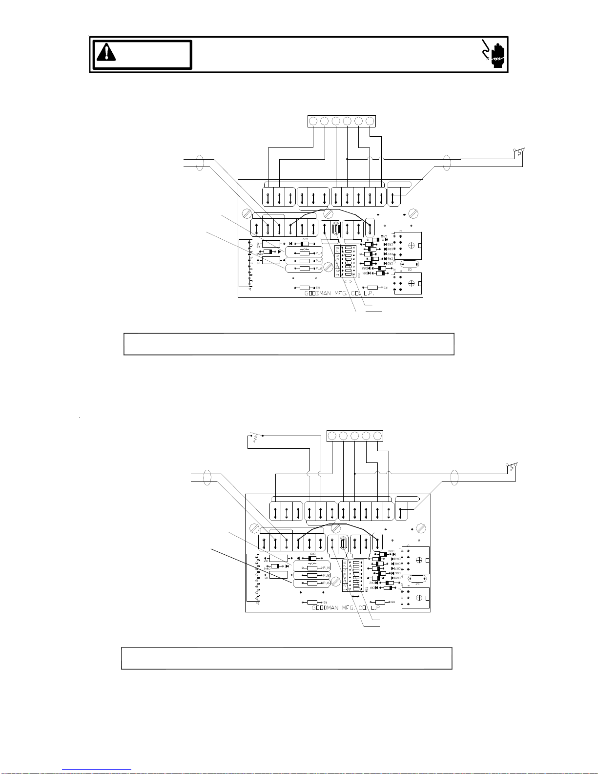
HEAT PUMP WITH SINGLE OR TWO STAGE HEATING WITH CONVENTIONAL THERMOSTAT
(OPTIONS FOR EMERGENCY HEAT)
ROOM
HEATPUMP
RYCO
W2
THERMOSTAT
W2
ECRG
O
Y
HEATPUMP
YCONR COM O W2 ED
NOTES:
1.) Y ENABLES HI SPD FAN COOLING
2.) E AND W2 ENABLE HI SPD FAN HEATING
3.) IF OT2 PJ2 JUMPER IS CUT E AND W2 ENABLE
LO SPD FAN HEATING
4.)
CUT HUM PJ6 JUMPER IF USING HUMIDISTAT
STAT OPENS ON HUMIDITY RISE
5.) DIP SWITCH #4 MUST BE IN THE "ON" POSITION
HEATPUMP - WITH 1 STG EMHT 1 STG AUX HEAT
CO
HEATPUMP
O
W2
W2 ED
YR
CONDENSER
YCON COM
YCONR
COM O W2 ED
PLEASE REFER
TO MANUAL
FOR PROPER
DIP SWITCH
(CFM)
CONFIGURATION.
THERMOSTATS
OUTDOOR
HEATPUMP
W1
W2
OT1
OT2
HUM
Figure 23
E
IF NEEDED
OT2OT1 Y1W/W2E\W1 C ROOTC
W1 W2
HEATER
SWITCH
DIP
THERMOSTAT
W2
O
C R
24 VAC
ON
ROOM
C
IF
N
EE
D
E
HUMIDISTAT
HUMIDISTAT
HUMGY/Y2
(OPTIONAL)
REMOVE
PRODUCTION
Y1
OFF
YG
R
WIRE Y1-O
HUMIDISTAT
(OPTIONAL)
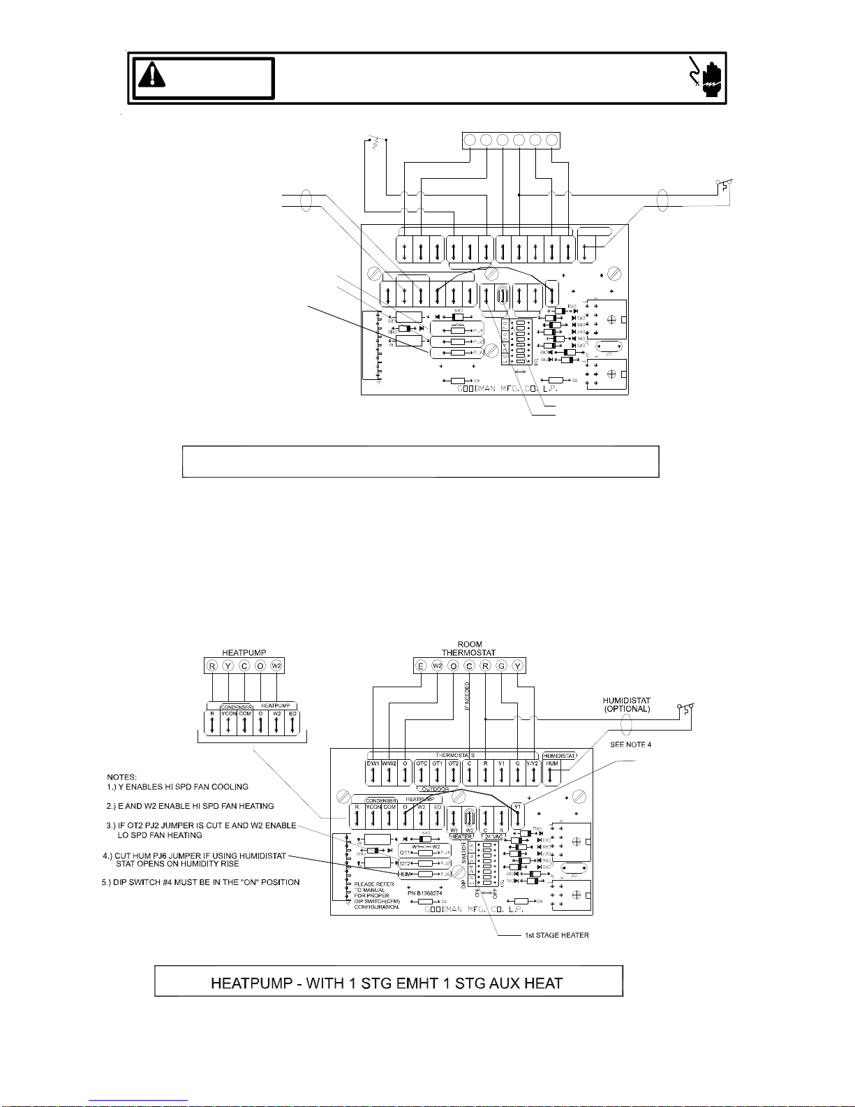
NOTES:
1.) Y ENABLES HI SPD FAN COOLING
2.)
E ENABLES LOW SPD FAN HEATING
W2 ENABLES HI SPD FAN HEA TI N G
3.) OT1 PJ4 MUST BE CUT FOR THIS CONFIGURATION
4.) CUT HUM PJ6 JUM PER IF USING HUMIDI STAT
STAT OPENS ON HUMIDITY RISE
5.) DIP SWITCH #4 MUST BE IN THE “ON” POSITION
HEATPUMP - 2 STG EMHT 1 STG AU X HEAT
Wiring is subject to change, always refer to the wiring diagram on the unit for the most up-to-date wiring.
CONDENSER
YCON COM
R
R2
CR10
R1
PLEASE REFER
TO MANUAL
FOR PR OPER
DIP SWITCH
J1
CONFIGU RATI O N.
O
W/W2E\W1
HEATPUMP
O
W2 ED
W1 W2
OT1
OT2
HUM
PN B1368274
Figure 24
15
THERMO STATS
OT1OTC
OUTDOOR
CR9
Y1RCGY/Y2OT2 HUM
HUMIDISTAT
SEE NOTE 4
REMOVE
PRODUCTION
Y1
CR
W2W1
24 VAC
S
WI
PJ4
TC
H
PJ2
PJ6
DI
P
R3
CR2
CR1
12345678
DS1
O
O
FF
N
5
1
CR11
CR3
CR8
CR7
CR6
CR5
C2
J2 J3
4
1
2nd STAGE HEATER
1st STAG E H E ATER
WIRE Y1-O
Page 16

WARNING
HIGH VOLTAGE!
DISCO NNECT ALL POWER BEFORE SERV ICING.
MULTIPLE POWER SOURCES MAY BE PRESENT. FAILURE TO DO SO
MAY CAUSE PROPERTY DAMAGE, PERSONAL INJURY OR DEATH.
HEATPUMP
W2
HEATPUMP
COM W2
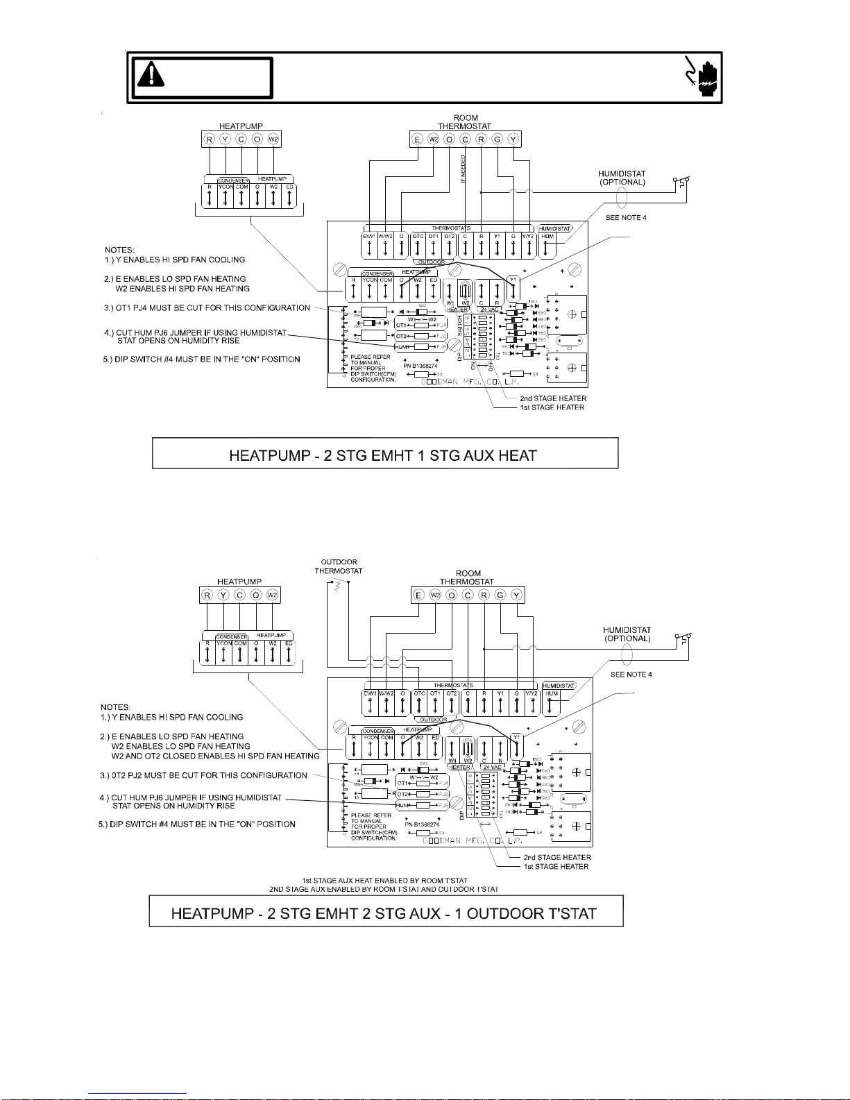
NOTES:
1.) Y ENABLES HI SPD FAN COOLING
2.) E ENABLES LO SP D FAN HEATING
W2 ENAB LES L O W SPD FAN HEATING
W2 AND OT2 CLOS ED EN A BLES HI SPD FAN H EATING
3.) OT1 PJ2 MUST BE CUT FOR THIS CONFIGURATION
4.) CUT HUM PJ6 JUMPER IF USING HUMIDISTAT
STAT OPENS ON HUMIDITY RISE
5.) DIP SWITCH #4 MUST BE IN THE "ON" POSITION
HEATPUMP - 2 STG EMHT 2 STAG AUX - 1 OUTDOOR T-STAT
OUTDOOR
THERMOSTAT
J1
O
W/W2E\W1
HEATPUM P
COM
W1 W2
OT1
OT2
HUM
PN. B1368274
Figure 25
ROOM
THERMOSTAT
W2
IF NEEDED
THERMO STATS
OT1OTC
OUTDOOR
W2
W1
W2
24 VAC
PJ4
PJ2
PJ6
DI
12345678
P
GOODMAN MFG. CO. L.P.
HUMIDISTAT
Y/Y2OT2 HUM
5
1
J2 J3
4
1
2nd STAGE HEATER
1ST STAGE HEATER
HUMIDISTAT
(OPTIONAL)
SEE NOTE 4
REMOVE
PRODUCTION
WIRE Y1-O
CONDEN SER
COM
RYCON
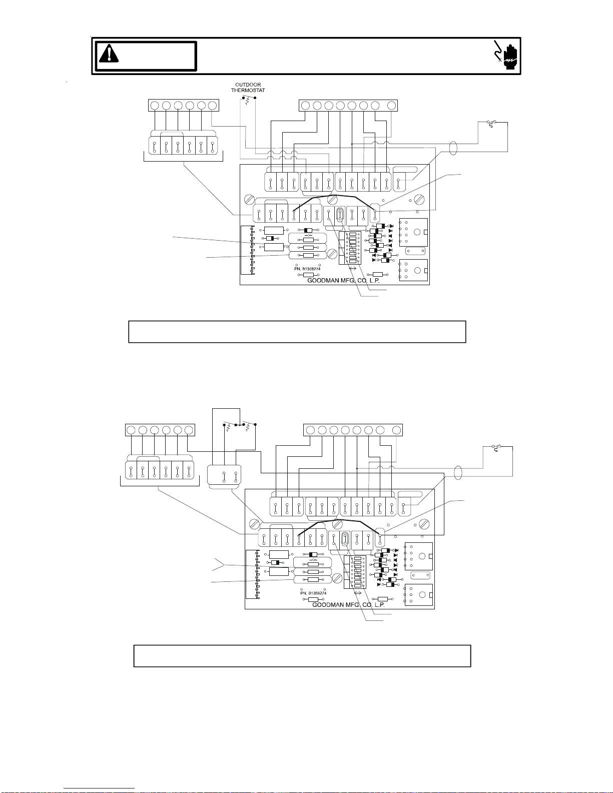
NOTES:
1.) Y ENABLES HI SPD FAN COOLING
2.)
E ENABLES LOW SPD FAN HEATING
W2 AND O T1 CLOSED ENABLES LOW SPD FAN HEATING
W2 AND O T2 CLOSED ENABLES HI SPD FAN HEATING.
3.) IF OT2 PJ4 AND OT2 PJ2 MUST BE CUT FOR THIS
CONFIGURATION
4.) CUT HUM PJ6 JUMPER IF USING HUMIDISTAT
STAT OPENS ON HUMIDITY RISE
ED
5.) DIP SWITCH #4 MUST BE IN THE “ON” POSITION
NO AUX HEAT IN HEATPUMP MODE UNT IL OUTDOO R T’STAT CLOSES
CONDENSER
RYCONCOM
J1
O
HUM
PN. B13682704
Figure 26
ROOM
THERMOSTATHEATPUMP
IF
HUMIDISTAT
(OPTIONAL)
SEE NOTE 4
RC HUM
REMOVE
PRODUCTION
ED
CR
TC
H
DS1
N
5
1
J2 J3
4
1
WIRE Y1-O
Wiring is subject to change, always refer to the wiring diagram on the unit for the most up-to-date wiring.
16
Page 17

WARNING
HIGH VOLTAGE!
DISCO NNECT ALL POWER BEFORE SERV ICING.
MULTIPLE POWER SOURCES MAY BE PRESENT. FAILURE TO DO SO
MAY CAUSE PROPERTY DAMAGE, PERSONAL INJURY OR DEATH.
OUTDOOR
THERMOSTAT
W2
THERMOSTAT
W2
ROOM
HEATPUMP
W2
COM
NOTES:
1.) Y ENABLES HI SPD FAN COOLING
2.) E ENABLES LO SPD FAN HEATING
W2 AND OT2 CLOSED ENABLES HI SPD FAN HEATING
3.) OT1 PJ4 AND OT2 PJ2 MUST BE CUT
FOR THIS CONFIGURATION
4.) CUT HUM PJ6 JUMPER IF USING HUMIDISTAT
STAT OPENS ON HUMIDITY RISE
5.) DIP SWITCH #4 MUST BE IN THE "ON" POSITION
IF NEEDED
THERMOSTATS
W/W2E\W1
COM W2
J1
OT1OTC
O
OUTDOOR
HEATPUMP
W1
W1 W2
PJ4
OT1
PJ2
OT2
PN. B1368274
PJ6
DI
P
HUM
GOODMAN MFG. CO. L.P.
W2
24 VAC
12345678
HUMIDISTAT
Y/Y2OT2 HUM
1
J2 J3
1
2nd STAGE HEATER
1ST STAGE HEATER
HUMIDISTAT
(OPTIONAL)
SEE NOTE 4
REMOVE
PRODUCTION
5
4
WIRE Y1-O
HEATPUMP - 2 STG EMHT 1 STG AUX - 1 OUTDOOR T'STAT
Figure 27
2 SPEED HEAT PUMP WITH SINGLE OR TWO-STAGE HEATING
(OPTIONS FOR EMERGENCY HEAT) WITH CONVENTIONAL TWO-STAGE THERMOSTAT
HEATPUMP
COM W2
NOTES:
1.) Y ENABLES HI SPD FAN COOLING
2.)
E ENABLES LOW SPD FAN HEATING
3.) IF OT2 PJ2 JUMBER IS CUT “E’ AND “W2”
ENABLE LOW SPD FAN HEATING
4.) CUT HUM PJ6 JUMPER IF USING HUMIDISTAT
STAT OPENS ON HUMIDITY RISE
5.) DIP SWITCH #4 MUST BE IN THE “OFF” POSITION
HEATPUMP - WITH 1 STG EMHT 1 STG AUX HEAT
Wiring is subject to change, always refer to the wiring diagram on the unit for the most up-to-date wiring.
ROOM
W2
O
W/W2E\W1
HEATPUMP
COM
W1 W2
OT1
OT2
HUM
J1
PN. B1368274
THERMOSTAT
W2
IF NEEDED
THERMOSTATS
OT1OTC
OUTDOOR
W2
W2W1
24 VAC
PJ4
PJ2
PJ6
DI
12345678
P
GOODMAN MFG. CO. L.P.
HUMIDISTAT
Y/Y2OT2 HUM
5
1
J2 J3
4
1
2nd STAGE HEATER
1st STAGE HEATER
HUMIDISTAT
(OPTIONAL)
SEE NOTE 4
REMOVE
PRODUCTION
WIRE Y1-O
Figure 28
17
Page 18

WARNING
HIGH VOLTAGE!
DISCO NNECT ALL POWER BEFORE SERV ICING.
MULTIPLE POWER SOURCES MAY BE PRESENT. FAILURE TO DO SO
MAY CAUSE PROPERTY DAMAGE, PERSONAL INJURY OR DEATH.
2 SPD HEATPUMP
W2
HEATPUMP
O
W2 ED
Y1
Y2R
CO
CONDENSER
YCON COM
R
NOTES:
1.) Y ENABLES HI SPD FAN COOLING
2.) E AND W2 ENABLE HI SPD FAN COOLING
3.) IF OT2 PJ2 JUMPER IS CU T “E” AND “W2”
ENABLE LOW SPD FAN HEATING
4.) CUT HUM PJ6 JUMPER IF USING HUMIDISTAT
STAT OPENS ON HUMIDITY RISE
5.) DIP SWITCH #4 MUST BE IN THE “OFF” POSITION
HEAT PUMP - WITH 1 STG EMHT 1 STG AUX HEAT
W/W2E\W1
CONDENSER
R
YCON
R2
CR10
R1
PLEASE REFER
TO MANUAL
FOR PROPER
DIP SWITCH
J1
CONFIGURATION.
W2
EC
THERMOSTATS
OT1OTC
O
OUTDOOR
HEATPUMP
COMOW2 ED
CR9
W1 W2
OT1
OT2
HUM
Figure 29
ROOM
THERMOSTAT
O
IF NEEDED
W1
W2
S
WI
PJ4
TC
H
PJ2
PJ6
DI
12345678
P
O
N
R3
RY2G
Y1RC G Y/Y2OT2 HUM
R
C
24 VAC
DS1
O
FF
Y1
HUMIDISTAT
Y1
1
CR11
CR3
CR8
CR7
CR6
CR5
CR2
J2 J3
CR1
1
2nd STAGE HEATER
1st STAGE HEATER
5
4
C2
HUMIDISTAT
(OPTIONAL)
SEE NOTE 4
REMOVE
PRODUCTION
WIRE Y1-O
2 SPD HEATPUMP
W2 W2
CO
CONDENSER
COMOW2 ED
RYCON
NOTES:
1.) Y ENABLES HI SPD FAN COOLING
2.)
E ENABLES LOW SPD FAN HEATING
W2 ENABLES HI SPD FAN HEATING
3.) IF OT2 PJ4 MUST BE CUT FOR THIS
CONFIGURATION
4.) CUT HUM PJ6 JUMPER IF USING HUMIDISTAT
STAT OPENS ON HUMIDITY RISE
Y1 Y1
HEATPUMP
5.) DIP SWITCH #4 MUST BE IN THE “OFF” POSITION
HEAT PUMP - 2 STG EMHT 1 STG AUX HEAT
CONDENSER
RYCON
R2
CR10
R1
PLEASE REFER
TO MANUAL
FOR PROPER
J1
DIP SWITCH
CONFIGURATION.
ECY2R RY2G
O
W/W2E\W1
HEATPUMP
O
W2 ED
COM
W1 W2
OT1
OT2
HUM
Figure 30
THERMOSTATS
OT1OTC
OUTDOOR
CR9
PJ4
PJ2
PJ6
ROOM
THERMOSTAT
O
IF NEEDED
W2W1
C
24 VAC
S
WI
TC
H
DI
12345678
P
O
N
R3
Y1RC G Y/Y2OT2 HUM
Y1
R
CR2
CR1
DS1
O
FF
1st STAGE HEATER
HUMIDISTAT
5
1
CR11
CR3
CR8
CR7
CR6
CR5
C2
J2 J3
4
1
2nd STAGE HEATER
HUMIDISTAT
(OPTIONAL)
SEE NOTE 4
REMOVE
PRODUCTION
WIRE Y1-O
Wiring is subject to change, always refer to the wiring diagram on the unit for the most up-to-date wiring.
18
Page 19
WARNING
HIGH VOLTAGE!
DISCO NNECT ALL POWER BEFORE SERV ICING.
MULTIPLE POWER SOURCES MAY BE PRESENT. FAILURE TO DO SO
MAY CAUSE PROPERTY DAMAGE, PERSONAL INJURY OR DEATH.
2-SPD HEATPUMP
Y2R
CONDENSER
COM
RYCON
NOTES:
1.) Y ENABLES HI SPD FAN COOLING
2.)
E ENABLES LOW SPD FAN HEATING
W2 ENABLES LOW SPD FAN HEATING
W2 AND OT2 CLOSED ENABLES HI SPD
FAN HEATING.
3.) IF OT2 PJ4 MUST BE CUT FOR THIS
CONFIGURATION
4.) CUT HUM PJ6 JUMPER IF USING HUMIDISTAT
STAT OPENS ON HUMIDITY RISE
HEATPUMP
O
W2 ED
Y1
W2
CO
5.) DIP SWITCH #4 MUST BE IN THE “OFF” POSITION
2ND STAGE AUX ENABLED BY ROOM T’STAT AND OUTDOOR T’STAT
HEATPUMP - 2 STG EMHT 2 STG AUX - 1 OUTD OOR T'S TAT
ROOM
THERMOSTAT
W2
E
O
C
R
IF NEEDED
THERMOSTATS
OT1OTC
O
W/W2E\W1
OUTDOOR
HEATPUMP
CONDENSER
RYCONCOMOW2 ED
CR9
W1
C
W2
R2
CR10
R1
PLEASE REFER
TO MANUAL
FOR PROPER
J1
DIP SWITCH
CONFIGURATION.
HUM
OT1
OT2
W1 W2
PJ4
PJ2
PJ6
24 VAC
S
WI
TC
H
DI
12345678
P
O
O
FF
N
R3
1ST STAGE AUX HEAT ENABLED BY ROOM T’STAT
Figure 31
Y2G
Y1
Y1
CR2
CR1
DS1
1st STAGE HEATER
HUMIDISTAT
CR11
2nd STAGE HEATER
Y1RC G Y/Y2OT2 HUM
R
HUMIDISTAT
(OPTIONAL)
SEE NOTE 4
REMOVE
PRODUCTION
WIRE Y1-O
5
1
CR3
CR8
CR7
CR6
CR5
C2
J2 J3
4
1
2 SPD HEATPUMP
W2 W2
CO
CONDENSER
COMOW2 ED
RYCON
NOTES:
1.) Y ENABLES HI SPD FAN COOLING
2.)
E ENABLES LOW SPD FAN HEATING
W2AND OT1 CLOSED ENABLES LOW SPD FAN HEATING
W2 AND OT2 CLOSED ENABLES HI SPD FAN HEATING.
3.) OT1 PJ4 AND OT2 PJ2 MUST BE CUT FOR THIS
CONFIGURATION
4.) CUT HUM PJ6 JUMPER IF USING HUMIDISTAT
STAT OPENS ON HUMIDITY RISE
Y1 Y1O
HEATPUMP
OT1
OT1 OT2OTC
OUTDOOR
5.) DIP SWITCH #4 MUST BE IN THE “OFF” POSITION
NO AUX HEAT IN HEATPUMP MODE UNTIL OUTDOOR T’STAT CLOSES
HEAT PUMP - 2 STG EMHT 2 STG AUX - 2 OUTDOOR T'STATS
OT2
CONDENSER
RYCON
R2
CR10
R1
PLEASE REFER
TO MANUAL
FOR PROPER
DIP SWITCH
J1
CONFIGURATION.
ECY2R RY2G
OTCW/W2E\W1
O
OUTDOOR
HEATPUMP
COMOW2 ED
W1 W2
OT1
OT2
HUM
Figure 32
ROOM
THERMOSTAT
THERMOSTATS
OT1
CR9
W1
S
WI
PJ4
TC
H
PJ2
PJ6
DI
P
R3
IF NE E DED
W2
12345678
O
N
Y1RC G Y/Y2OT2 HUM
Y1
R
C
24 VAC
CR2
CR1
DS1
O
FF
HUMIDISTAT
5
1
CR11
CR3
CR8
CR7
CR6
CR5
J2 J3
4
1
2nd STAGE HEATER
1st STAGE HEATER
C2
HUMIDISTAT
(OPTIONAL)
SEE NOTE 4
REMOVE
PRODUCTION
WIRE Y1-O
Wiring is subject to change, always refer to the wiring diagram on the unit for the most up-to-date wiring.
19
Page 20

WARNING
2-SPD HEATPUMP
CO
Y2R
HIGH VOLTAGE!
DISCO NNECT ALL POWER BEFORE SERV ICING.
MULTIPLE POWER SOURCES MAY BE PRESENT. FAILURE TO DO SO
MAY CAUSE PROPERTY DAMAGE, PERSONAL INJURY OR DEATH.
OUTDOOR
THERMOSTAT
W2
Y1
E
ROOM
THERMOSTAT
W2
O
Y2G
C
R
Y1
CONDENSER
RYCON
COM
HEATPUMP
O
W2 ED
IF NEEDED
HUMIDISTAT
(OPTIONAL)
SEE NOTE 4
Y1
CR2
CR1
DS1
1st STAGE HEATER
HUMIDISTAT
5
1
CR11
CR3
CR8
CR7
CR6
CR5
C2
J2 J3
4
1
2nd STAGE HEATER
REMOVE
PRODUCTION
WIRE Y1-O
NOTES:
1.) Y ENABLES HI SPD FAN COOLING
2.)
E ENABLES LOW SPD FAN HEATING
W2 AND OT2 CLOSED ENABLES HI SPD
FAN HEATING
3.) OT1 PJ4 AND OT2 PJ2 MUST BE CUT FOR THIS
CONFIGURATION
4.) CUT HUM PJ6 JUMPER IF USING HUMIDISTAT
STAT OPENS ON HUMIDITY RISE
5.) DIP SWITCH #4 MUST BE IN THE “OFF” POSITION
CONDENSER
RYCON
R2
CR10
R1
PLEASE REFER
TO MANUAL
FOR PROPER
J1
DIP SWITCH
CONFIGURATION.
THERMOSTATS
OT1OTC
O
W/W2E\W1
OUTDOOR
HEATPUMP
O
W2 ED
COM
CR9
W1 W2
PJ4
OT1
PJ2
OT2
PJ6
HUM
R3
W2W1
S
WI
TC
H
DI
P
12345678
C
24 VAC
O
O
FF
N
Y1RC G Y/Y2OT2 HUM
R
NO AUX HEAT IN HEATPUMP MODE UNTIL T’STAT CLOSES
HEATPUMP - 2 STG EMHT 1 ST G AUX - 1 OUTD OOR T'S TAT
Figure 33
TWO STAGE COOLING WITH CONVENTIONAL TWO STAGE THERMOSTAT
(ENCLOSED WITH ADD ON 1N006 DIODES)
TSTWK01 KIT REQUIRED
TO Y ON
TSTWK01 BOARD
1N4005
2 SPD REMOTE
DIODES
CONDENSING
UNIT
TO COMMON ON
24 V
230 V
TSTWK01
TRANSFORMER
TSTWK01 BOARD
TSTWK01
BOARD
ENCODED THERMOSTAT
TEST
ZD3
ZD2
ZD1
PLEASE RE FER
TO MANUAL
FOR PROPER
PN. B136 8271 REV. A
NOTES:
1.) STAT OPENS ON HUMIDITY RISE
2.) DIP SWITCH #4 MUST BE IN THE ON POSITION
DIP SWITCH
CONFIGURATION.
HEATPUMP
HUM
PN. B1368274
THERMOSTATS
PJ4
PJ2
PJ6
Y1 Y/Y2 HUM
24 VAC
CUT OT1 PJ4 FOR 2-STAGE HEAT OPERATION
CUT HUM PJ6 FOR HUMIDISTAT OPERATION
ENCODE D 2 SP D COOLING - WITH 1 OR 2-STG HEAT
HUMIDISTAT
Y1
2ND STAGE HEATER
1ST STAGE HEATER
Figure 34
Wiring is subject to change, always refer to the wiring diagram on the unit for the most up-to-date wiring.
20
HUMIDISTAT
HUMIDISTAT
(OPTIONAL)
(OPTIONAL)
SEE NOTE 1
Page 21

WARNING
R
2 SPD REMOTE
CONDENSING
UNIT
24 V
230 V
HIGH VOLTAGE!
DISCO NNECT ALL POWER BEFORE SERV ICING.
MULTIPLE POWER SOURCES MAY BE PRESENT. FAILURE TO DO SO
MAY CAUSE PROPERTY DAMAGE, PERSONAL INJURY OR DEATH.
TO Y ON
TSTWK01 BOARD
OUTDOOR
THERMOSTAT
W1
W2
TO COMMON ON
TSTWK01 BOARD
TSTWK01
BOARD
ENCODED THERMOSTAT
PN. B1368 271 REV. A
NOTES:
1.) OT2 CLOSED AND W2 DEMAND ENABLES
2.) STAT OPENS ON HUMIDITY RISE
3.) DIP SWITCH #4 MUST BE IN THE ON POSITION
OT1
OT2
HUM
OTCE\W1
OUTDOOR
W2
W1 W2
THERMOSTATS
OT1
W1
PJ4
PJ2
PJ6
Y/Y2OT2 HUM
W2
24 VAC
DI
P
2ND STAGE HEATER
1ST STAGE HEATER
CUT OT2 PJ2 FOR THIS CONFIGURATION
CUT HUM PJ6 FOR HUMIDISTAT OPERATION
HUMIDISTAT
HUMIDISTAT
(OPTIONAL)
SEE NOTE 2
TSTWK01
TRANSFORMER
ENCO D ED 2 SPD COO LI NG - WITH 1 OR 2 STG HEAT - 1 OT
Figure 35
ENCODED TWO STAGE COOLING WITH GMC THERMOSTAT PART #CHET18-60
TSTWKO1 KIT REQUIRED
TO Y ON
TSTWK01 BOARD
CHET 18-60
ENCODED
2 SPD REM O T E
CONDENSING
UNIT
24 V
Y1
Y2
TO COMMON ON
TSTWK01 BOARD
TSTWK01
BOARD
Y/Y2
YLO/Y1
C/X
THERMOSTAT
GOODMAN MFG. CO. L.P.
NOTES:
1.) STAT OPENS ON HUMIDITY RISE
2.) DIP SWITCH #4 MUST BE IN THE ON POSITION
CONDENSER
COMOW2 ED
RYCON
PLEASE REFER
TO MAN UAL
FOR PROPER
DIP SWITCH
CONFIGURATION.
THERMOSTATS
OT1OTCW/W2E\W1
OUTDOOR
HEATPUMP
W1
W1 W2
PJ4
OT1
PJ2
OT2
PJ6
HUM
GOODMAN MFG. CO. L.P.
HUMIDISTAT
Y1RC G Y/Y2OT2 H UM
Y1
R
C
W2
24 VAC
S
WI
TC
H
DI
12345678
P
O
O
FF
N
2ND STAGE HEATER
1ST STAGE HEATER
CUT OT2 PJ2 FOR 2-STAGE HEAT OPERATION
CUT HUM PJ6 FOR HUMIDISTAT OPERATION
HUMIDISTAT
(OPTIONAL)
SEE NOTE 1
TSTWK01
TRANSFORME
Wiring is subject to change, always refer to the wiring diagram on the unit for the most up-to-date wiring.
ENCODED 2 SPD COOL ING - WIT H 1 OR 2 STG HEAT
Figure 36
21
Page 22

WARNING
2 SPD REM O T E
CONDENSING
UNIT
TSTWK01
TRANSFORMER
HIGH VOLTAGE!
DISCO NNECT ALL POWER BEFORE SERV ICING.
MULTIPLE POWER SOURCES MAY BE PRESENT. FAILURE TO DO SO
MAY CAUSE PROPERTY DAMAGE, PERSONAL INJURY OR DEATH.
TO Y ON
TSTWK01 BOARD
CHET 18-60
ENCODED
Y1
Y2
TO COMMON ON
TSTWK01 BOARD
TSTWK01
BOARD
Y/Y2
YLO/Y1
C/X
THERMOSTAT
ENCODED THERMOSTAT
ZD3
ZD2
K3
Q2
GOODMAN MFG. CO. L.P.
ZD1
Q1
K1
K2
PN. B1368271 REV. A
NOTES:
1.) OT2 CLOSED AND W2 DEMAND ENABLES
2ND STG HEAT AND HI FAN
2.) STAT OPENS ON HUMIDITY RISE
3.) DIP SWITCH #4 MUST BE IN THE ON POSITION
RYCONCOM
P1
PLEASE REFER
TO MAN UAL
FOR PROPER
DIP SWITCH
J1
CONFIGURATION.
OUTDOOR
THERMOSTAT
W/W2E\W1
OUTDOOR
HEATPUMP
O
W2 ED
W1 W2
OT1
OT2
HUM
GOODMAN MFG. CO. L.P.
THERMOSTATS
OT1OTC
PJ4
PJ2
PJ6
Y1RC G Y/Y2OT2 HUM
RY1W2W1
C
24 VAC
S
WI
TC
H
DI
12345678
P
O
O
FF
N
CUT HUM PJ6 FOR HUMIDISTAT OPERATION
ENCODED 2 SPD COOLING - WITH 1 OR 2 STG HEAT - 1 OT
Figure 37
HUMIDISTAT
(OPTIONAL)
HUMIDISTAT
J2 J3
2ND STAGE HEATER
1ST STAGE HEATER
CUT OT2 PJ2 FOR THIS CONFIGURATION
SEE NOTE 2
INPUT
FROM
THERMOSTAT
POWER
TO
THERMOSTAT
Troubleshooting Encoded Two Stage Cooling Thermostats Options
T
E
S
T
TEST FUNCTION SIGNAL OUT SIGNAL FAN
INDICATION
S1 +
* S1 - *
S1 + -
S2 +
S2 -
S2 + -
S3 +
* S3 - *
* S3 + - *
R + COM
NOTES:
1.) THE TEST SPADE CAN BE CONNECTED TO ANY OTHER TEST SPADE ON EITHER BOARD.
2.) THE + LED WILL BE RED AND WILL LIGHT TO INDICATE + HALF CYCLES.
THE - LED WILL BE GREEN AND WILL LIGHT TO INDICATE - HALF CYCLES.
BOTH RED AND GREEN ILLUMINATED WILL INDICATE FULL CYCLES DENOTED BY + - .
3.) SIGNAL OUT CONDITION FOR W1 , W2 HEATER WILL BE AFFECTED BY OT1 PJ4 AND OT2 PJ2
JUMPERS AND OUTDOOR THERMOSTATS ATTACHED. THE TABLE ABOVE ASSUMES OT1 PJ4 IS
REMOVED AND OT2 PJ2 IS MADE WITH NO OUTDOOR THERMOSTATS ATTACHED.
LOW SPEED COOL
* LO SPEED COOL *
HI SPEED COOL
LO SPEED HEAT
O
LO SPEED HEAT
HI SPEED HEAT
G
N/A
N/A
24 VAC
GND
YCON +
* YCON - *
YCON + -
W1 HEATER
ED -
( FUTURE USE )
W1 HEATER
W2 HEATER
NONE
N/A
N/A
R TO T'STAT
COM TO T'STAT
Y1
* Y / Y2 HI *
Y / Y2
W / W1
O
W / W1
EM / W2
G
N/A
N/A
R
C1 , C2
* ERROR CONDITION ( DIODE ON THERMOSTAT BACKWARDS )
SEE NOTE 3
SEE NOTE 3
* ERROR CONDITION ( S3 CAN ONLY READ + )
* ERROR CONDITION ( S3 CAN ONLY READ + )
The chart above provides troubleshooting for either version of the encoded thermostat option. This provides diagnostic information for the GMC CHET18-60 or a conventional two cool / two stage heat thermostat with IN4005 diodes added as called out in
the above section.
Wiring is subject to change, always refer to the wiring diagram on the unit for the most up-to-date wiring.
22
Page 23

A test lead or jumper wire can be added from the test terminal
to any terminal on the B13682-74 or B13682-71 variable speed
terminal board and provide information through the use of the
LED lights on the B13682-71 VSTB control. Using this chart,
a technician can determine if the proper input signal is being
received by the encoded VSTB control and diagnose any problems that may be relayed to the output response of the B1368274 VSTM control.
Example:
st
The system is calling for 1
stage cooling operation. The proper
input signal from either thermostat option will cause the red “+”
LED light to illuminate when the test terminal and the “S1”
terminal are connected using a test lead or jumper wire. This
verifies proper input from the thermostat. The proper output is
a “YCON” signal to the RSG condensing unit. When a test
lead or jumper is connected between Test and YCON, the red
“+” LED will illuminate. The corresponding response from the
CKTS control will be an illuminated “LOW” LED light and 24V
applied to the Low capacity contactor through the “LOW” terminal output.
This similar procedure can be utilized on any terminal on the
VSTB controls. The chart above indicates the proper input and
LED status as well as the corresponding out signal. Each
mode of operation must be verified during the check out procedure when the units are installed. The LED light provides a
easy method to verify operation without the use of a multimeter.
23
Page 24

All of our systems are designed and manufactured with the same high quality standards regardless of size or efficiency.
We have designed these units to significantly reduce the most frequent causes of product failure. They are simple to
service and forgiving to operate. We use quality materials and components. Finally, every unit is run tested before it
leaves the factory. That’s why we know . . . There’s No Better Quality.
Visit our websites at www.goodmanmfg.com or www.amana-hac.com for information on:
Quality Makes the Difference!
• Products
• Warranties
• Customer Services
• Parts
• Contractor Programs and Training
• Financing Options
© 2004-2009 Goodman Manufacturing Company , L.P .
24
 Loading...