

Page 1
LPM-08
TWO-STAGE FURNACE, NATURAL GAS TO LP GAS CONVERSION KIT
INSTALLATION INSTRUCTIONS
ATTENTION INSTALLING PERSONNEL
As a professional installer, you have an obligation to know
the product better than the customer. This includes all safety
precautions and related items.
Prior to actual installation, thoroughly familiarize yourself with
this Instruction Manual. Pay special attention to all safety
warnings. Often during installation or repair, it is possible to
place yourself in a position which is more hazardous than
when the unit is in operation.
Remember, it is your responsibility to install the product safely
and to know it well enough to be able to instruct a customer
in its safe use.
Safety is a matter of common sense...a matter of thinking
before acting. Most dealers have a list of specic good safety
practices...follow them.
The precautions listed in this Installation Manual are intended
as supplemental to existing practices. However, if there is a
direct conict between existing practices and the content of
this manual, the precautions listed here take precedence.
RECOGNIZE THIS SYMBOL
AS A SAFETY PRECAUTION
DESCRIPTION
This natural gas to L.P. (liquid petroleum) gas conversion
kit allows White-Rodgers gas valve 36G54 (0151F00000P),
36J54 (0151M00027) or Honeywell VR9205Q (0151M00014
/ 0151M00028) to be used on L.P. gas applications.
Use the following parts list to ensure that all parts listed below
are present and in an undamaged condition. IF ANY DOUBT
EXISTS ABOUT THE CONDITIONS OF ANY COMPONENT
WITHIN THIS KIT, DO NOT USE THIS KIT AND CONTACT
YOUR SUPPLIER FOR A NEW KIT.
PARTS LIST
Part
Number
0163F00000P White-Rodgers LP Conversion Kit F92-1008 1
0163M00139 Honeywell LP Conversion Kit 50033841 1
B14933151 Conversion Label 1
B40899125 1.25mm Spud Orice Assembly 1
IO-818 LPM-08 Installation Instructions 1
0151K00000S 36G54 Pressure Check Kit Valve 1
Description Quantity
With the exception of the natural gas burner orices, all of
the fasteners and other components removed to perform
this conversion are to be reused. Any component found to
be damaged due to this conversion must be replaced with
factory authorized replacement parts before this furnace can
be put into o peration.
This furnace is equipped for two-stage heating operation.
The gas valve manifold pressure must be set with rst stage
operating at 6” +/-0.3” W.C. manifold pressure and the second
stage must be set at 10” +/-0.3” W.C. manifold pressure. The
accuracy of these pressures must be checked as shown in
steps 25 and 26 of these instructions.
The gas valve is equipped with a 3-pin polarized plug which
prevents this wiring from being installed incorrectly.
CAUTION
LabeL aLL wires prior to disconnection when servicing
controLs. wiring errors can cause improper and dangerous
operation. verify proper operation after servicing.
NOTE: Do not use power tools for any adjustments on
gas valves.
IO-818
01/2014
Page 2

CONTENTS
CARBON MONOXIDE POISONING HAZARD
B10259-216
Carbon monoxide producing devices (such as an automobile, space
heater, gas water heater, etc.) should not be operated in enclosed areas
such as unventilated garages, utility rooms or parking areas because of
the danger of carbon monoxide (CO) poisoning resulting from the exhaust
emissions. If a furnace or air handler is installed in an enclosed area such
as a garage, utility room or parking area and a carbon monoxide producing
device is operated therein, there must be adequate, direct outside
ventilation.
This ventilation is necessary to avoid the danger of CO poisoning which
can occur if a carbon monoxide producing device continues to operate in
the enclosed area. Carbon monoxide emissions can be (re)circulated
throughout the structure if the furnace or air handler is operating in any
mode.
CO can cause serious illness including permanent brain damage or death.
Special Warning for Installation of Furnaces or Air Handling Units in
Enclosed Areas such as Garages, Utility Rooms or Parking Areas
Important Information ......................................................... 2
Conversion Instructions - WR 36G54 or 36J54 Valves ...... 3
Conversion Instructions - HW VR9205Q Valve .................. 5
NOx Screen Removal ......................................................... 7
Non-Condensing Furnaces & Package Gas-Electric.......... 7
WARNING
carbon monoXide (co) can cause sever personaL
injury or death.
WARNING
The following tools and supplies are required:
• 2 – Pipe wrenches, properly sized to accommodate the
gas piping and connectors
• 1 – 7/16” box wrench or socket wrench
• 1 - 1/4” nut driver
• 1 – 3/16” at blade screwdriver
• 1 – 1/4” at blade screwdriver
• 1 – 3/16” allen wrench
• 1 – manometer to read inlet and outlet pressure of the
gas valve (Minimum range: 0”-20” W.C.)
• Pipe joint compound or pipe thread tape that is approved for use with L.P. gas
• Gas leak detection solution like a soap and water
solution. Always wipe the solution from the joints when
testing is completed.
WARNING
never use an open fLame to check for gas Leaks.
this L.p. (Liquid petroLeum) conversion kit must be
instaLLed by a quaLified service person or agency in
accordance with the manufacturer’s instructions and
aLL appLication codes and requirements of the authority
having jurisdiction. faiLure to foLLow these instructions
eXpLicitLy may cause a fire, eXpLosion or the
production of carbon monoXide (co), which
can cause property damage, personaL
injury or death. the quaLified person performing
this conversion assumes the responsibiLity for the proper
conversion of the appLiance.
Prior to performing this conversion, refer to the National Fuel
Gas Code (NFPA 54-02) or in Canada, CAN/CSA-B149.2-05
to ensure that the installation is in compliance with those
and all local codes.
IMPORTANT INFORMATION
WARNING
high voLtage!
disconnect aLL power before servicing.
muLtipLe power sources may be present. faiLure
do so may cause property damage, personaL
to
or death.
injury
2
Page 3
WHITE-RODGERS 36G54 OR 36J54
CONVERSION INSTRUCTIONS
WARNING
high voLtage!
disconnect aLL power before servicing.
muLtipLe power sources may be present. faiLure
do so may cause property damage, personaL
to
or death.
injury
CAUTION
if noX screens are present, remove as per instructions in
section “noX screen removaL.”
CAUTION
to prevent unsatisfactory furnace operation, the proper
gas conversion kit must be used for the gas vaLve. use the
white-rodgers spring kit onLy with the white-rodgers
gas vaLve.
NOTE: For low NOx models, see table of contents for
NOx screen section.
1. Turn off the gas supply to the furnace.
2. Turn off the electrical power to the furnace.
3. Remove the furnace control access panel.
4. Check for the presence of NOx screen and remove per
NOx instruction.
5. Separate the gas supply union and remove associated
downstream piping.
6. Always use a backup wrench when removing or replacing
piping to avoid any undue strains or rotation of controls.
7. Remove the wires from the gas valve.
8. Remove the 4 sheet metal screws that fasten the manifold/
gas valve assembly to the burner box.
9. Visually inspect orices for damage and drill size (marked
on face with 1.25mm) before installation. Using the 7/16”
wrench, remove all existing natural gas orices and replace with the appropriate 1.25mm L.P. gas orices contained in this kit. Tighten the orices to prevent gas leaks,
but do not overtighten. Retain the natural gas orices for
future reconversion.
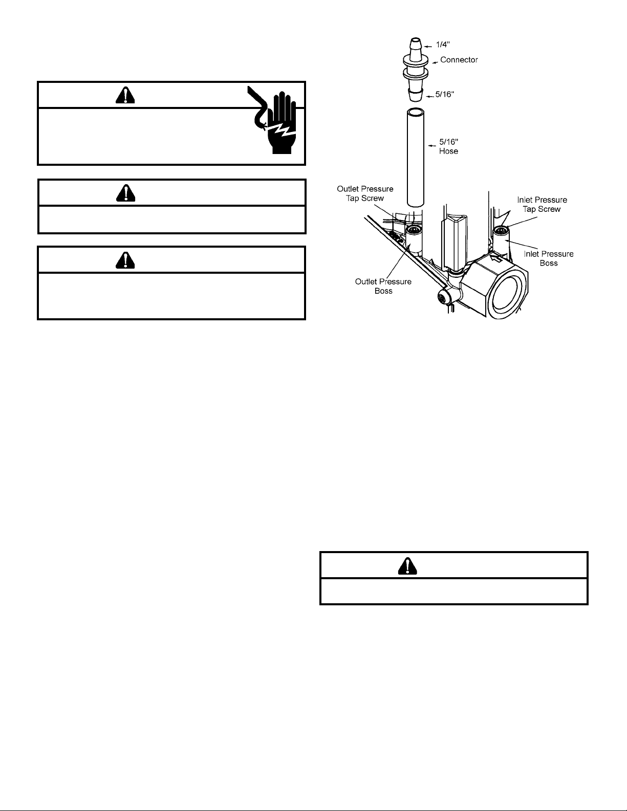
10. Install water manometer using Valve Pressure Check Kit
P/N 0151K00000S included with this kit. Using the included 3/32” hex wrench, rotate outlet pressure tap screw one
revolution counterclockwise. Attach the included 5/16”
hose to the inlet and outlet pressure boss of the valve.
Hose should overlap boss 3/8”. Connect 5/16” side of included connector to the hose on the outlet boss. Connect
1/4” side of the connector to the manometer hose. The
manometer must have a scale range of at least 0” to 20”
of water column.
11. Remove both regulator cover screws.
12. Using a 1/4” at blade screwdriver, remove both regulator
adjustment screws (beneath the cover screws).
13.Remove both Natural Gas regulator springs (color-coded
silver/plain) from regulator sleeves and retain with the
Natural Gas orices for future reconversion.
14. Insert the L.P. regulator springs (provided in the conversion kit and color-coded white) into the regulator sleeves.
15. Replace the High regulator adjustment screw and adjust
approximately 12 turns to the bottom stop.
16. Replace the Low regulator adjustment screw and adjust
approximately 8 turns.
17. Reinstall the manifold/gas valve assembly into the appliance. Rewire the gas valve.
18. Apply a liberal amount of pipe joint compound or pipe
thread tape to the threads and reassemble the piping
previously removed.
WARNING
to prevent the possibiLity of gas Leaks, the pipe joint com-
pound or pipe thread tape must be resistant to L.p. gas.
19. Turn on the gas supply.
20. Using a soap and water solution, check for leaks around
the gas valve/manifold connection.
21. Turn on the electrical supply.
22. Adjust the room thermostat to obtain a rst stage (W1
only) burner operation.
NOTE: for hybrid models, the control board dip switches
need to be set to 2 stg position to set and verify rst stage
heat. (See Installation Instructions supplied with the unit for
dip switch settings)
3
Page 4

WARNING
never use an open fLame to check for gas Leaks.
23. Using a soap and water solution, check for leaks around
the gas valve/manifold connection and the burner orices.
Repair any leaks before continuing.
24. NOTE: Any other gas-red equipment should be ON
before any adjustments are made.
After the furnace has been in operation for 15 minutes,
adjust the gas supply pressure (not manifold pressure) to
obtain a range between 11” and 13” W.C. If the gas inlet
pressure falls outside of this range, then make necessary
L.P. service regulator(s) adjustments; check piping size,
etc., and /or consult with L.P. provider.
25. With the furnace operating in its low-re (W1) condition, the
manifold pressure should be 6” W.C. ± 0.30”. If necessary,
this pressure can be adjusted using the gas valve low
regulator adjustment screw. Turn clockwise to increase
pressure and counterclockwise to decrease manifold
pressure.
26. Readjust the room thermostat to obtain a second stage
call for heat (W2). The manifold pressure for the W2
condition should be 10” W.C. ± 0.30” W.C. Adjustments
to this pressure can be made using the high regulator
adjustment screw.
27. Using the room thermostat to cycle the unit, observe a
minimum of three (3) smooth ignition cycles.
28. Turn off gas and electrical supply to the furnace, remove
the manometer hose from the pressure tap bosses, and
tighten the inlet and outlet pressure tap screws using the
3/32” Allen wrench.
29. Replace both regulator cover screws on the regulator
sleeve.
White-Rodgers 36G54 or 36J54
WARNING
attach the warning LabeL provided in the kit to the gas
vaLve where it can be readiLy seen.
attach the smaLL, round L.p. LabeLs to the top of the
reguLator cover screws.
30. IMPORTANT NOTE: Apply the conversion label (B14933-
151) provided with the conversion kit. This label must be
attached adjacent to the rating plate.
31. For hybrid models, control board switches may need to be
re-set to single stage operation depending on installers
preference of operation.
32. Reinstall the access panels.
33. Turn on the gas and electrical supply.
34. Reset all other appliances so they function normally.
White-Rodgers 36G54 or 36J54
Springs and Regulator Screws
4
Page 5

HONEYWELL VR9205Q
CONVERSION INSTRUCTIONS
WARNING
high voLtage!
disconnect aLL power before servicing.
muLtipLe power sources may be present. faiLure
do so may cause property damage, personaL
to
or death.
injury
CAUTION
if noX screens are present, remove as per instructions in
section “noX screen removaL.”
CAUTION
to prevent unsatisfactory furnace operation, the proper
gas conversion kit must be used for the gas vaLve. use the
honeyweLL spring kit onLy with the honeyweLL gas vaLve.
NOTE: For low NOx models, see table of contents for NOx
screen section.
1. Turn off the gas supply to the furnace.
2. Turn off the electrical power to the furnace.
3. Remove the furnace control access panel.
4. Check for the presence of NOx screen and remove per
NOx instruction.
5. Separate the gas supply union and remove associated
downstream piping.
6. Always use a backup wrench when removing or replacing
piping to avoid any undue strains or rotation of controls.
7. Remove the wires from the gas valve.
8. Remove the 4 sheet metal screws that fasten the manifold/
gas valve assembly to the burner box.
9. Visually inspect orices for damage and drill size (marked
on face with 1.25mm) before installation. Using the 7/16”
wrench, remove all existing natural gas orices and replace with the appropriate 1.25mm L.P. gas orices contained in this kit. Tighten the orices to prevent gas leaks,
but do not overtighten. Retain the natural gas orices for
future reconversion.
10. Remove both the inlet and outlet plugs on the gas valve,
using the 3/16” allen wrench. Install the ttings, which
accompany the manometers, into the 1/8” NPT holes of
the gas valve. Connect the manometers to the barbed
ttings.
Honeywell VR9205Q
11. Remove both regulator cover screws and retain with the
Natural Gas orices for future reconversion.
12. Using a T-25 Torx driver (L Torx tool included in kit) or 3/16”
at head screwdriver, remove both regulator adjustment
screws.
13. Remove both silver colored Natural Gas regulator springs
from the regulator sleeves and retain with the Natural Gas
orices for future reconversion.
14. Insert the L.P. regulator springs (provided in the conversion
kit and color-coded red) into the regulator sleeves.
15. Install the high regulator adjustment screw provided with
the kit by threading all the way down until lightly seated
and then back off 1 1/2 turns.
16. Install the low regulator adjustment screw provided with
the kit by threading all the way down until lightly seated
and then back off 1 1/2 turns.
17. Reinstall the manifold/gas valve assembly into the appliance. Rewire the gas valve.
WARNING
to prevent the possibiLity of gas Leaks, the pipe joint com-
pound or pipe thread tape must be resistant to L.p. gas.
18. Apply a liberal amount of pipe joint compound or pipe
thread tape to the threads and reassemble the piping
previously removed. NOTE: the pipe joint compound must
be resistant to L.P. gas.
19. Turn on the gas supply.
20. Using a soap and water solution, check for leaks around
the gas valve/manifold connection.
21. Turn on the electrical supply.
22. Adjust the room thermostat to obtain a rst stage (W1
only) burner operation.
NOTE: for hybrid models, the control board dip switches
need to be set to 2 stg position to set and verify rst stage
heat. (See Installation Instructions supplied with the unit for
dip switch settings)
5
Page 6

WARNING
WARNING
never use an open fLame to check for gas Leaks.
23. Using a soap and water solution, check for leaks around
the gas valve/manifold connection and the burner orices.
Repair any leaks before continuing.
24. NOTE: Any other gas-red equipment should be ON
before any adjustments are made.
After the furnace has been in operation for 15 minutes,
adjust the gas supply pressure (not manifold pressure) to
obtain a range between 11” and 13” W.C. If the gas inlet
pressure falls outside of this range, then make necessary
L.P. service regulator(s) adjustments; check piping size,
etc., and /or consult with local L.P. provider.
25. With the furnace operating in its low-re (W1) condition,
the manifold pressure should be 6” W.C.± 0.30”. If necessary, this pressure can be adjusted using the low regulator
adjustment screw. Turn clockwise to increase pressure
and counterclockwise to decrease manifold pressure.
26. Readjust the room thermostat to obtain a second stage call
for heat (W2). The manifold pressure for the W2 condition
should be 10” ± 0.30” W.C. Adjustments to this pressure
can be made using the high regulator adjustment screw.
27. Using the room thermostat to cycle the unit, observe a
minimum of three (3) smooth ignition cycles.
28. Turn off gas and electrical supply to the furnace. Remove
the barbed manometer ttings from the 1/8” NPT holes in
the gas valve. Seal inlet and outlet plugs removed earlier
with pipe joint compound or pipe thread tape and reinstall.
to prevent the possibiLity of gas Leaks, the pipe joint
compound must be resistant to L.p. gas.
29. Install the regulator cover screws provided with the conversion kit.
WARNING
instaLL the attention LabeL provided with the conversion
kit to the gas vaLve where it can be readiLy seen.
30. IMPORTANT NOTE: Apply the conversion label (B14933-
151) provided with the conversion kit. This label must be
attached adjacent to the rating plate.
31. For hybrid models, control board switches may need to be
re-set to single stage operation depending on installers
preference of operation.
32. Reinstall the access panels.
33. Turn on the gas and electrical supply.
34. Reset all other appliances so they function normally.
6
Page 7

NOX SCREEN REMOVAL
WARNING
aLL metaL screens must be removed from the heat eXchanger
tubes when using propane gas. faiLure to compLy with this
requirement wiLL aLso void warranty coverage.
NOTE: To prevent premature heat exchanger failure, follow the instructions below to remove all metal screen inserts
from the entrance of heat exchanger tubes during propane conversions. Not all models will have metal screen inserts.
NON-CONDENSING FURNACES AND PACKAGE GAS-ELECTRIC
1. Remove the screws securing the burner box to the partition panel. Separate burner box from unit.
2. Remove the screw(s) securing the NOx screen retention plate and remove the plate.
3. Remove and discard NOx screens.
4. Reinstall the NOx screen retention plate and burner box.
Typical NOx Screen Removal
7
Page 8

NOTE: SPECIFICATIONS AND PERFORMANCE DATA LISTED HEREIN ARE SUBJECT TO CHANGE WITHOUT NOTICE
®
Quality Makes the Difference!
All of our systems are designed and manufactured with the same high quality standards regardless of size or
efciency. We have designed these units to signicantly reduce the most frequent causes of product failure. They
are simple to service and forgiving to operate. We use quality materials and components. Finally, every unit is run
tested before it leaves the factory. That’s why we know. . .There’s No Better Quality.
Visit our website at www.daikincomfort.com, www.goodmanmfg.com or www.amana-hac.com for information on:
• Products
• Warranties
• Customer Services
• Parts
• Contractor Programs and Training
• Financing Options
5151 San Felipe, Suite 500, Houston, TX 77056
© 2014 Goodman Manufacturing Company, L.P.
is a trademark of Maytag Corporation and is used under license. All rights reserved.
8
 Loading...