

Page 1
LPM-07
NATURAL GAS TO LP GAS CONVERSION KIT
INSTALLATION INSTRUCTIONS
ATTENTION INSTALLING PERSONNEL
As a professional installer, you have an obligation to know
the product better than the customer. This includes all safety
precautions and related items.
Prior to actual installation, thoroughly familiarize yourself with
this Instruction Manual. Pay special attention to all safety
warnings. Often during installation or repair, it is possible to
place yourself in a position which is more hazardous than
when the unit is in operation.
Remember, it is your responsibility to install the product safely
and to know it well enough to be able to instruct a customer
in its safe use.
Safety is a matter of common sense...a matter of thinking
before acting. Most dealers have a list of specic good safety
practices...follow them.
The precautions listed in this Installation Manual are intended
as supplemental to existing practices. However, if there is a
direct conict between existing practices and the content of
this manual, the precautions listed here take precedence.
RECOGNIZE THIS SYMBOL
AS A SAFETY PRECAUTION
DESCRIPTION
This natural gas to L.P. gas conversion kit allows the
36G22 [B1282628, 36J22 (0151M00037)] and VR-8215
(0151M00013) series gas valves to be used on L.P. gas
applications. This conversion kit is for use on all single stage
maximum regulation valves.
Required Tools for Kit Installation
2 Pipe wrenches, properly sized to accommodate the
gas piping and connectors
1 7/16” box wrench or socket wrench
1 1/4” nut driver
1 1/4” regular (atblade) screwdriver
1 Manometers to read inlet & outlet pressure of the gas value
(minimum range: 0” - 20” W.C.)
1 3/16” Allen wrench
2 1/8” NPT hose barb
Pipe joint compound or pipe thread tape that is approved for
use with L.P. gas
Gas leak detection solution, like a soap and water solution.
Always wipe the solution from the joints when testing is
complete.
WARNING
To avoid The possibiliTy of explosion or fire, never use a
maTch or open flame To TesT for leaks.
Prior to performing this conversion refer to the National
Fuel Gas Code (ANSI Z223.1) or in Canada, CAN/CGAB149.2-M91 to ensure that the installation is in compliance
with those and all local codes.
PLEASE READ AND FOLLOW THESE INSTRUCTIONS
CAREFULLY.
WARNING
To avoid The possibiliTy of explosion or fire, never use a
maTch or open flame To TesT for leaks.
WARNING
The manufacTurer will noT be responsible for any
injury or properTy damage arising from improper service
or service procedures. This l.p. (liquid peTroleum)
conversion kiT musT be insTalled by a qualified service
person oragency in accordance wiTh The manufacTurer’s
insTrucTions and all applicable codes and requiremenTs of
The auThoriTy having jurisdicTion.
failure To follow These insTrucTions expliciTly may cause
a fire, explosion or The producTion of carbon monoxide,
which can cause properTy damage, personal injury or
deaTh.
if you insTall or perform service on This uniT, you assume
responsibiliTy
may resulT. many jurisdicTions require a license To
which
insTall
for any personal injury or properTy damage
or service heaTing and air condiTioning equipmenT.
KIT CONTENTS
Using the following parts list, ensure that all parts included
in this list are present and in an undamaged condition.
Quantity Part Number Description
1 B10259108 Conversion Label
1 B1880007 Spring Kit for White-Rodgers
36G22 & 36J22 valves
1 0163M00078 Spring Kit for Honeywell
VR8215 Value
1 B40899125 1.25mm Burner Orice
1 IO-817 Installation Instructions
1 0151K00000S Pressure Check Kit Value
IO-817
01/2014
Page 2
CONTENTS
CARBON MONOXIDE POISONING HAZARD
B10259-216
Carbon monoxide producing devices (such as an automobile, space
heater, gas water heater, etc.) should not be operated in enclosed areas
such as unventilated garages, utility rooms or parking areas because of
the danger of carbon monoxide (CO) poisoning resulting from the exhaust
emissions. If a furnace or air handler is installed in an enclosed area such
as a garage, utility room or parking area and a carbon monoxide producing
device is operated therein, there must be adequate, direct outside
ventilation.
This ventilation is necessary to avoid the danger of CO poisoning which
can occur if a carbon monoxide producing device continues to operate in
the enclosed area. Carbon monoxide emissions can be (re)circulated
throughout the structure if the furnace or air handler is operating in any
mode.
CO can cause serious illness including permanent brain damage or death.
Special Warning for Installation of Furnaces or Air Handling Units in
Enclosed Areas such as Garages, Utility Rooms or Parking Areas
Important Information ......................................................... 2
Conversion Instructions - WR 36G22 or 36J22 Valves ...... 3
Conversion Instructions - HW VR8215 Valve ..................... 5
NOx Screen Removal ......................................................... 6
Non-Condensing Furnaces & Package Gas-Electric.......... 6
IMPORTANT INFORMATION
WARNING
To avoid personal injury, properTy damage or deaTh, due
To leaking gas, conTacT your propane supplier abouT
insTalling a gas deTecTing warning device. iron oxide
(rusT) can reduce The level of odoranT in propane gas.
a gas deTecTing device is The only reliable meThod To
deTecT a propane gas leak.
WARNING
“This conversion kiT shall be insTalled by a qualified service
agency in accordance wiTh The manufacTurer’s insTrucTions
and all applicable codes and requiremenTs of The auThoriTy
having jurisdicTion. if The informaTion in These insTrucTions is
noT followed exacTly, a fire,
explosion or producTion of carbon monoxide may
resulT causing properTy damage, personal injury or loss
of life. The qualified service agency is responsible for
The proper insTallaTion of This kiT. The insTallaTion is noT
proper and compleTe unTil The operaTion of The converTed
appliance is checked as specified in The manufacTurer’s
insTrucTions supplied wiTh The kiT.”
CAUTION
To avoid The risk of properTy damage, personal injury or
fire, shuT off gas supply firsT, Then disconnecT The elec-
Trical supply before proceeding wiTh conversion.
BEFORE BEGINNING CONVERSION:
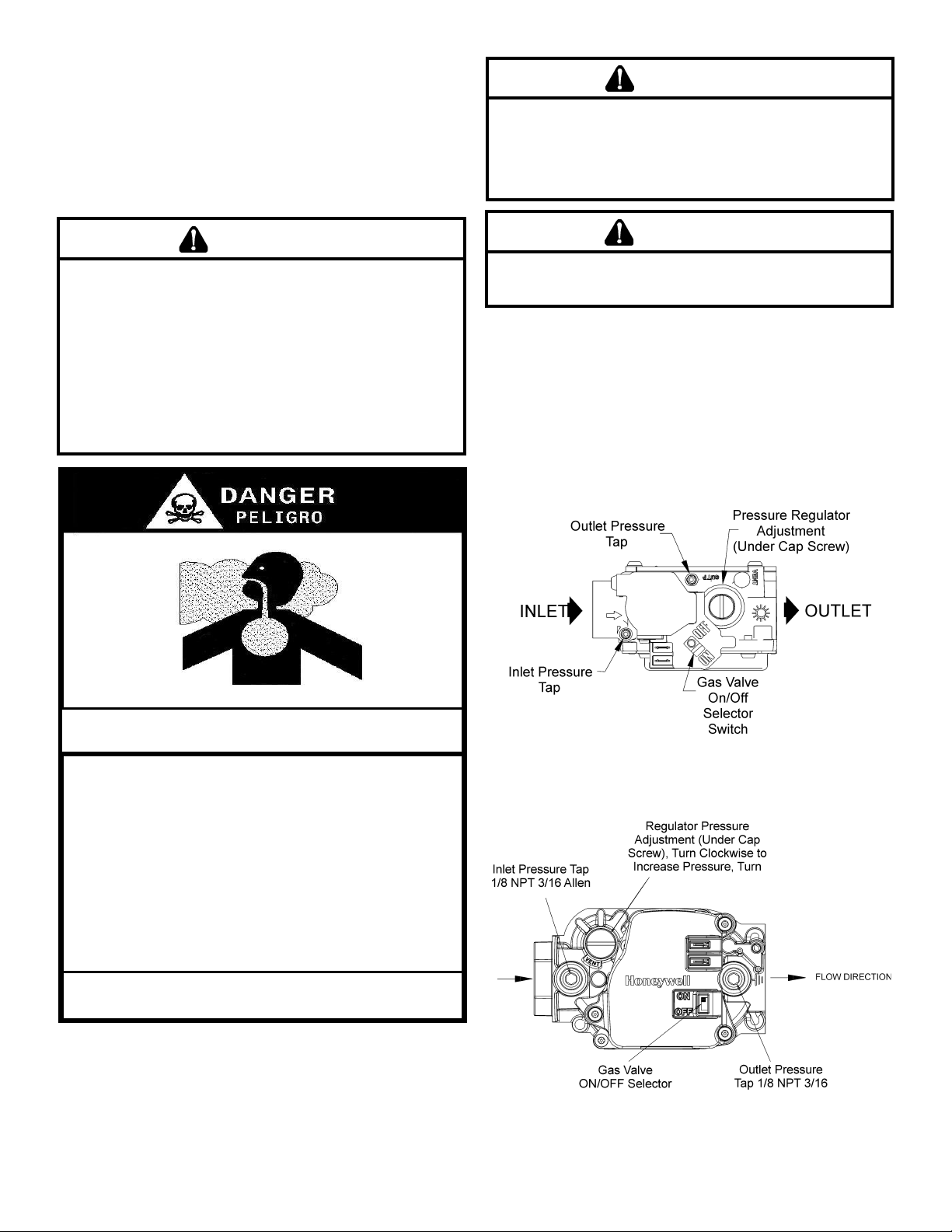
VALVE IDENTIFICATION
Before beginning conversion, the type valve you have
must be identied. Compare the gas valve presently on the
equipment to the drawing below to identify the correct valve
you are working with. Page numbers for the instructions for
that valve are below each drawing.
White-Rodgers 36G22 and 36J22
Instructions for these valves start on page 3.
Honeywell VR8215
Instructions for this valve start on page 5.
2
Page 3
WHITE-RODGERS 36G22 AND 36J22
CONVERSION INSTRUCTIONS
CAUTION
To prevenT unsaTisfacTory furnace operaTion, The
proper gas conversion kiT musT be used for The gas
valve. use The whiTe-rodgers spring kiT only wiTh The
whiTe-rodgers gas valves.
NOTE: For low NOx models, see page 6 for NOx screens.
1. Turn off gas supply to the furnace.
2. Turn off the electrical power to the furnace.
3. Remove the furnace control access panel.
4. Separate the gas supply union and remove associated
downstream piping.
NOTE: Always use a backup wrench when removing or
replacing piping to avoid any undue strains or rotation of
controls.
5. Remove the wires from the gas valve.
6. Remove the 4 sheet metal screws that fasten the manifold/
gas valve assembly to the burner box.
7. Visually inspect orices for damage and drill size (marked
on face with 1.25mm) before installation. Using the 7/16”
wrench, remove all existing natural gas orices and replace with the appropriate 1.25mm L.P. gas orices contained in this kit. Tighten the orices to prevent gas leaks,
but do not overtighten. Retain the natural gas orices for
future reconversion.
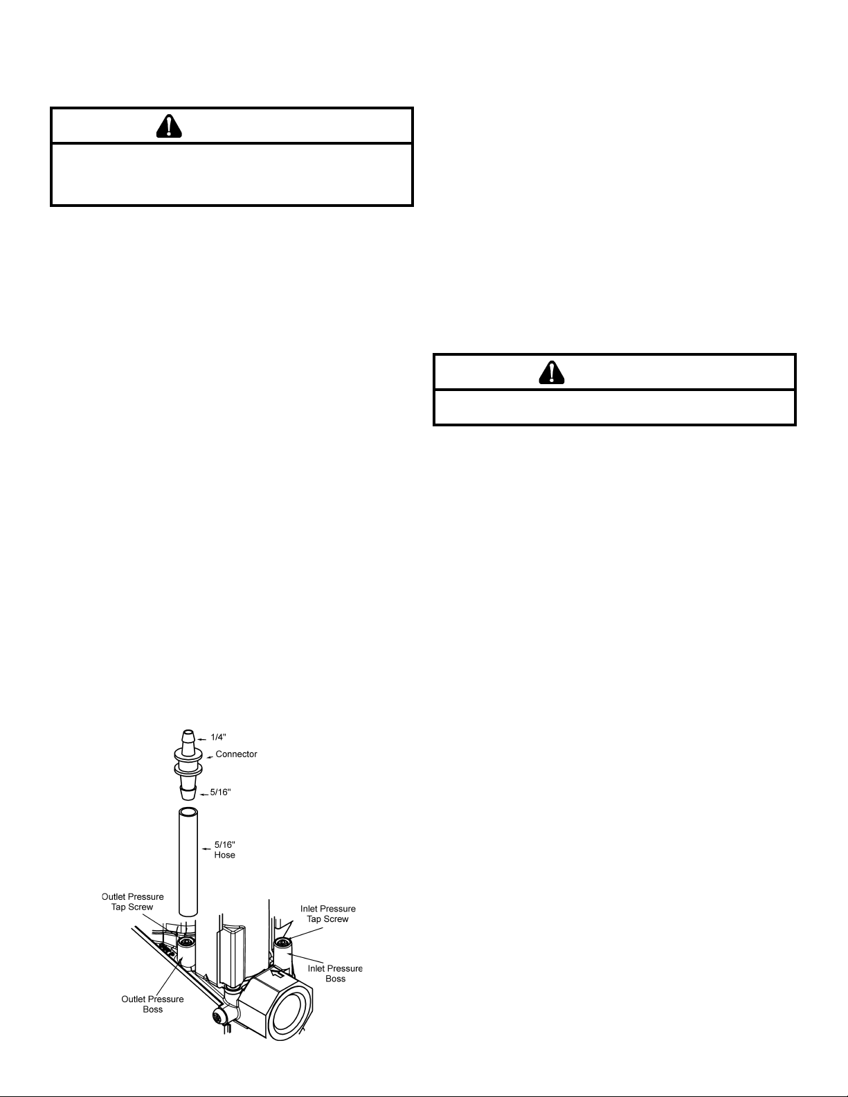
8. Install water manometer using Valve Pressure Check Kit
P/N 0151K00000S included with this kit. Using the included 3/32” hex wrench, rotate outlet pressure tap screw one
revolution counterclockwise. Attach the included 5/16”
hose to the inlet and outlet pressure boss of the valve.
Hose should overlap boss 3/8”. Connect 5/16” side of included connector to the hose on the outlet boss. Connect
1/4” side of the connector to the manometer hose. The
manometer must have a scale range of at least 0” to 20”
of water column.
9. Using a at blade screwdriver, remove the regulator cover
screw.
10. Using a at blade screwdriver, remove plastic regulator
adjustment screw located beneath the cover screw.
11. Remove the natural gas regulator spring from the regulator
sleeve.
12. Insert the kit (P/N B1880007, WR F92-0999) provided
L.P. regulator spring into the regulator sleeve.
13. Replace the regulator adjustment screw.
14. Reinstall the manifold/gas valve assembly into the appliance. Rewire the gas valve.
15. Apply a liberal amount of pipe joint compound or pipe
thread tape to the threads and reassemble the piping
previously removed. NOTE: the pipe joint compound or
pipe thread tape must be resistant to L.P. gas.
16. Turn on the gas supply and check for leaks.
WARNING
To avoid The possibiliTy of explosion or fire, never use a
maTch or open flame To TesT for leaks.
17. Turn on the electrical supply.
18. Adjust the room thermostat to allow for constant operation.
19. If you have the correct manifold pressure and the
burners do not light, there may be air trapped in the
lines. Follow these instructions:
To check for air trapped in the supply line: Verify line
pressure is in the correct range. If manifold pressure is
indicated during the ignition trial, the valve is opening and
air may be in the line.
Units with hot surface ignitors: The valve will not open
until the ignitor is at the proper temperature (glowing
brightly).
Units with spark ignition: The valve will open as soon
as the spark starts. If no manifold pressure is indicated
during the trial for ignition, please return to step 13 to
ensure the correct spring was used and to ensure the
regulator adjustment is near the bottom of the adjustment
range.
20. If gas inlet pressure falls outside the range of 11” and 13”
W.C. after the unit has been in operation for 15 minutes,
adjust the gas supply pressure (not manifold pressure),
check piping size, etc., and/or consult with local utility.
NOTE: Any other gas-red equipment should be ON
before any adjustments are made.
21. Check manifold pressure. For propane gas, the manifold
pressure must be between 9.7” and 10.3” W.C.
3
Page 4

22. Turn adjustment screw out (counterclockwise) to
decrease pressure, turn in (clockwise) to increase
pressure. Only small variations in gas ow should be
made by means of the pressure regulator adjustment.
In no case should the nal manifold pressure vary more
than plus or minus 0.3” water column from the specied
nominal pressure. Any major changes in ow should be
made by changing the size of the burner orices. The
measured input rate to the furnace must not exceed the
rating specied on the unit rating plate.
23. Reset all other appliances so they function normally.
24. Turn off gas and electrical supply to the furnace, remove
the manometer hose from the pressure tap bosses, and
tighten the inlet and outlet pressure tap screws using
the 3/32” Allen wrench (clockwise 7 in-lb minimum).
25. If regulator adjustment screw (removed in step 11) is
white, the gasket supplied with the kit must be installed
on the regulator cover screw. The gasket is not required
if the regulator adjustment screw is black.
26. Replace the regulator cover screw on the regulator
sleeve.
27. Attach the kit provided WARNING label to the gas valve
where it can be readily seen. Also attach the small
round L.P. label to the top of the regulator cover screw.
28. Turn on the gas and electrical supply, energize the
appliance and recheck for leaks.
29. Observe at least 3 ignition cycles to assure quick and
smooth ignition and burner operation.
30. Reinstall the access panels.
36G22 and 36J22 Model
CAUTION
To avoid The risk of properTy damage, personal injury
or fire, shuT off gas supply firsT, Then disconnecT The
elecTrical supply before proceeding wiTh conversion.
NOTE: Conversion instructions for the Honeywell
VR8215 gas valve begin on the following page.
4
Page 5

HONEYWELL VR8215
CONVERSION INSTRUCTIONS
CAUTION
To prevenT unsaTisfacTory furnace operaTion, The proper
gas conversion kiT musT be used for The gas valve. use The
honeywell spring kiT only wiTh The honeywell gas valve.
NOTE: For low NOx models, see page 6 for NOx screens.
1. Turn off gas supply to the furnace.
2. Turn off the electrical power to the furnace.
3. Remove the furnace control access panel.
4. Separate the gas supply union and remove associated
downstream piping.
NOTE: Always use a backup wrench when removing or
replacing piping to avoid any undue strains or rotation of
controls.
accompany the manometers into the 1/8” taped holes of
the gas valve. Connect the manometers to the barbed
ttings.
10. Using a at blade screwdriver, remove the regulator cover
screw.
11. Using a at blade screwdriver, remove plastic regulator
adjustment screw located beneath the cover screw.
12. Remove the natural gas regulator spring from the regulator
sleeve.
13. Insert the kit (P/N 0163M00078, Honeywell P/N 396221)
provided L.P. regulator spring into the regulator sleeve.
14. Replace the natural gas regulator adjustment screw with
the L.P. regulator adjustment screw included in the kit.
NOTE: The LP regulator should be adjusted near the bot-
tom of the adjustment range. DO NOT OVER-TIGHTEN.
15. Apply a liberal amount of pipe joint compound or pipe
thread tape to the threads and reassemble the piping
previously removed.
NOTE: the pipe joint compound or pipe thread tape must
be resistant to L.P. gas.
16. Turn on the gas supply and check for leaks.
WARNING
Honeywell VR8215
5. Remove the wires from the gas valve.
6. Remove the 4 sheet metal screws that fasten the manifold/
gas valve assembly to the burner box.
7. Visually inspect orices for damage and drill size (marked
on face with 1.25mm) before installation. Using the 7/16”
wrench, remove all existing natural gas orices and replace with the appropriate 1.25mm L.P. gas orices contained in this kit. Tighten the orices to prevent gas leaks,
but do not overtighten. Retain the natural gas orices for
future reconversion.
8. Reinstall the manifold/gas valve assembly into the appliance. Rewire the gas valve.
9. Remove both the inlet and outlet plugs on the gas valve,
using the 3/16” Allen wrench. Install the ttings which
To avoid The possibiliTy of explosion or fire, never use a
maTch or open flame To TesT for leaks.
17. Turn on the electrical supply.
18. Adjust the room thermostat to allow for constant operation.
19. To check for air trapped in the supply line: Verify line
pressure is in the correct range. If manifold pressure is
indicated during the ignition trial, the valve is opening and
air may be in the line.
Units with hot surface ignitors: The valve will not open
until the ignitor is at the proper temperature (glowing
brightly).
Units with spark ignition: The valve will open as soon
as the spark starts. If no manifold pressure is indicated
during the trial for ignition, please return to step 13 to
ensure the correct spring was used and to ensure the
regulator adjustment is near the bottom of the adjustment
range.
20. If gas inlet pressure falls outside the range of 11” and 13”
W.C. after the unit has been in operation for 15 minutes,
adjust the gas supply pressure (not manifold pressure),
check piping size, etc., and/or consult with local utility.
NOTE: Any other gas-red equipment should be ON
before any adjustments are made.
21. Check manifold pressure. For propane gas, the manifold
pressure must be between 9.7” and 10.3” W.C.
5
Page 6

22. Turn adjustment screw out (counterclockwise) to
decrease pressure, turn in (clockwise) to increase
pressure. Only small variations in gas ow should be
made by means of the pressure regulator adjustment.
In no case should the nal manifold pressure vary more
than plus or minus 0.3” water column from the specied
nominal pressure. Any major changes in ow should be
made by changing the size of the burner orices. The
measured input rate to the furnace must not exceed the
rating specied on the unit rating plate.
23. Reset all other appliances so they function normally.
24. Turn off the gas and electrical supply to the appliance,
remove the pressure taps at the gas valve, reinstall the
plugs using pipe joint compound or tape.
WARNING
To avoid The possibiliTy of explosion or fire, never use a
maTch or open flame To TesT for leaks.
25. Replace the regulator cover screw on the regulator
sleeve.
26. Attach the kit provided ATTENTION label to the gas
valve where it can be readily seen.
27. Turn on the gas and electrical supply, energize the
appliance and recheck for leaks.
28. Observe at least 3 ignition cycles to assure quick and
smooth ignition and burner operation.
29. Reinstall the access panels.
NON-CONDENSING FURNACES
AND PACKAGE GAS-ELECTRIC
1. Remove the screws securing the burner box to the
partition panel. Separate burner box from unit.
2. Remove the screw(s) securing the NOx screen retention
plate and remove the plate.
3. Remove and discard NOx screens.
4. Reinstall the NOx screen retention plate and burner box.
Typical NOx Screen Removal
NOx SCREEN REMOVAL
WARNING
remove all meTal screens from The heaT exchanger Tubes
when using propane gas. failure To do so may cause
properTy damage, personal injury or deaTh and will void
warranTy coverage.
NOTE: To prevent premature heat exchanger failure, follow
the instructions in the NON-CONDENSING FURNACES
AND PACAKGE GAS-ELECTRIC section to remove all
metal screen inserts from the entrance of heat exchanger
tubes during propane conversions. Not all models will have
metal screen inserts.
6
Page 7

THIS PAGE LEFT INTENTIONALLY BLANK
7
Page 8

NOTE: SPECIFICATIONS AND PERFORMANCE DATA LISTED HEREIN ARE SUBJECT TO CHANGE WITHOUT NOTICE
®
Quality Makes the Difference!
All of our systems are designed and manufactured with the same high quality standards regardless of size or
efciency. We have designed these units to signicantly reduce the most frequent causes of product failure. They
are simple to service and forgiving to operate. We use quality materials and components. Finally, every unit is run
tested before it leaves the factory. That’s why we know. . .There’s No Better Quality.
Visit our website at www.daikincomfort.com, www.goodmanmfg.com or www.amana-hac.com for information on:
• Products
• Warranties
• Customer Services
• Parts
• Contractor Programs and Training
• Financing Options
5151 San Felipe, Suite 500, Houston, TX 77056
© 2014 Goodman Manufacturing Company, L.P.
is a trademark of Maytag Corporation and is used under license. All rights reserved.
8
 Loading...