

Page 1
LPLP03
p
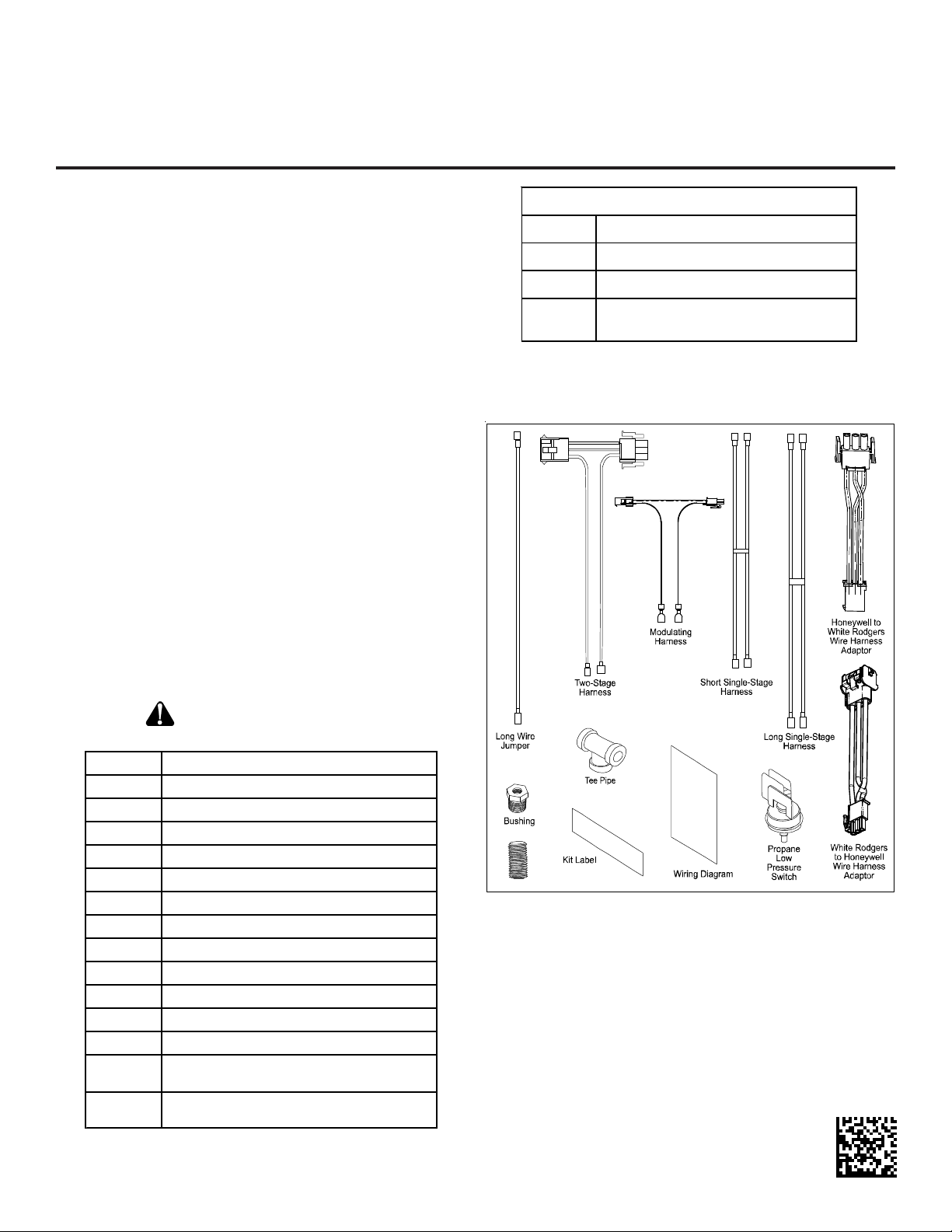
LOW PRESSURE PROPANE KIT
INSTALLATION INSTRUCTIONS
Description
This kit is designed for gas-fired units converted to propane
gas use. The Propane Low Pressure (LPLP03) Kit monitors
the gas line pressure with a pressure switch and disables the
unit gas valve if the line pressure drops below acceptable levels.
ATTENTION INSTALLING PERSONNEL
As a professional installer you have an obligation to know the
product better than the customer. This includes all safety
precautions and related items.
Prior to actual installation, thoroughly familiarize yourself with
this Instruction Manual. Pay special attention to all safety
warnings. Often during installation or repair it is possible to
place yourself in a position which is more hazardous than when
the unit is in operation.
Remember, it is your responsibility to install the product safely
and to know it well enough to be able to instruct a customer in
its safe use.
Safety is a matter of common sense...a matter of thinking before
acting. Most dealers have a list of specific good safety
practices...follow them.
The precautions listed in this Installation Manual are intended
as supplemental to existing practices. However, if there is a
direct conflict between existing practices and the content of
this manual, the precautions listed here take precedence.
Fie l d Suppl ied
1 1/2" x 1-1 / 2" Nippl e
11/2" Tee
1 90 Degree S treet E l b ow
1
NOTE:
installations. See figures inside this IO for application
needs.
1/2" P i pe (length dependent on
model and applic ation)
Field supplied parts are not required for all
1 Propane Low Pressure Switch
1 1/8" Close Nipple
1 1/ 8" Te e Pi pe
1 1/2" x 1/ 8" Bushing
1 Sho r t Singl e-Stage H arness
1 Long S i ngle - Stage Harness
1 Long Jum per Wire
1 Two-Stag e Harness
1 Modulating Wire Harness
1 Propane Low Pressure Kit Label
1Wiring Diagram
1
1
IO-775C
August 2014
RECOGNIZE THIS SYMBOL
AS A SAFETY PRECAUTION
Switch to Gas Valve Piping
Low Pressure Switch Wiring
Honeywell t o White-Ro dgers
Wire Harness Ada
White-Rodgers to Honeywell
Wire Harness Adaptor
tor
Figure 1
Page 2
CONTENTS
Important Information.......................................................... 2
Models Using White-Rodgers 36F & 36E
Gas V alves with 1/8” NPT
Inlet Pressure Port ............................................................. 3
White-Rodgers 36F & 36E V alves
Right Facing Gas Inlet............................................. 3
White-Rodgers 36F & 36E V alves
Left Facing Gas Inlet............................................... 4
White-Rodgers 36G/36J V alve
Right Facing Gas Inlet (Left Facing Similar) ............ 4
Honeywell VR82 and VR9205Q Valves
or VR9205R Modulating V alve on 90%+ models ..... 4
80% Models Using Honeywell VR82, VR92
or White-Rodgers 36G/36J gas valves...................... 4
Honeywell VR82 or VR92 V alve on 80% models ..... 5
LP Low Pressure Switch Wiring
(Single-Stage Models) ............................................. 5
LP Low Pressure Switch Wiring
(T wo-Stage Models White-Rodgers Gas V alve
and Wire Harness Connection) ............................... 5
LP Low Pressure Switch Wiring
(Two-S tage Models with White-Rodgers Gas Valve
with Honeywell Wire Harness Connection) .................. 6
90% Models Using Honeywell VR82, VR9205Q V alves or
VR9205R Modulating V alve or White-Rodgers 36G ..... 6
Short 90% Models Using Honeywell VR82, VR9205Q
V alves or VR9205R Modulating Valve or
White-Rodgers 36J V alve ............................................ 6
Troubleshooting.................................................................. 8
IMPORTANT INFORMA TION
This kit provides control over the unit gas valve by routing the
gas valve wiring through the supplied pressure switch. To enable proper fit-up, the pressure switch kit must be installed
before connecting the gas supply line to the gas valve. For
new unit installations, the kit hardware may be fitted to the gas
valve while the gas manifold is removed for LP gas orifice
conversion. For existing installations, the gas valve line must
be disconnected from the gas valve to allow fitting of kit hardware. Refer to Figures 2, 3, 4, 5 or 6 for a view of kit hardware
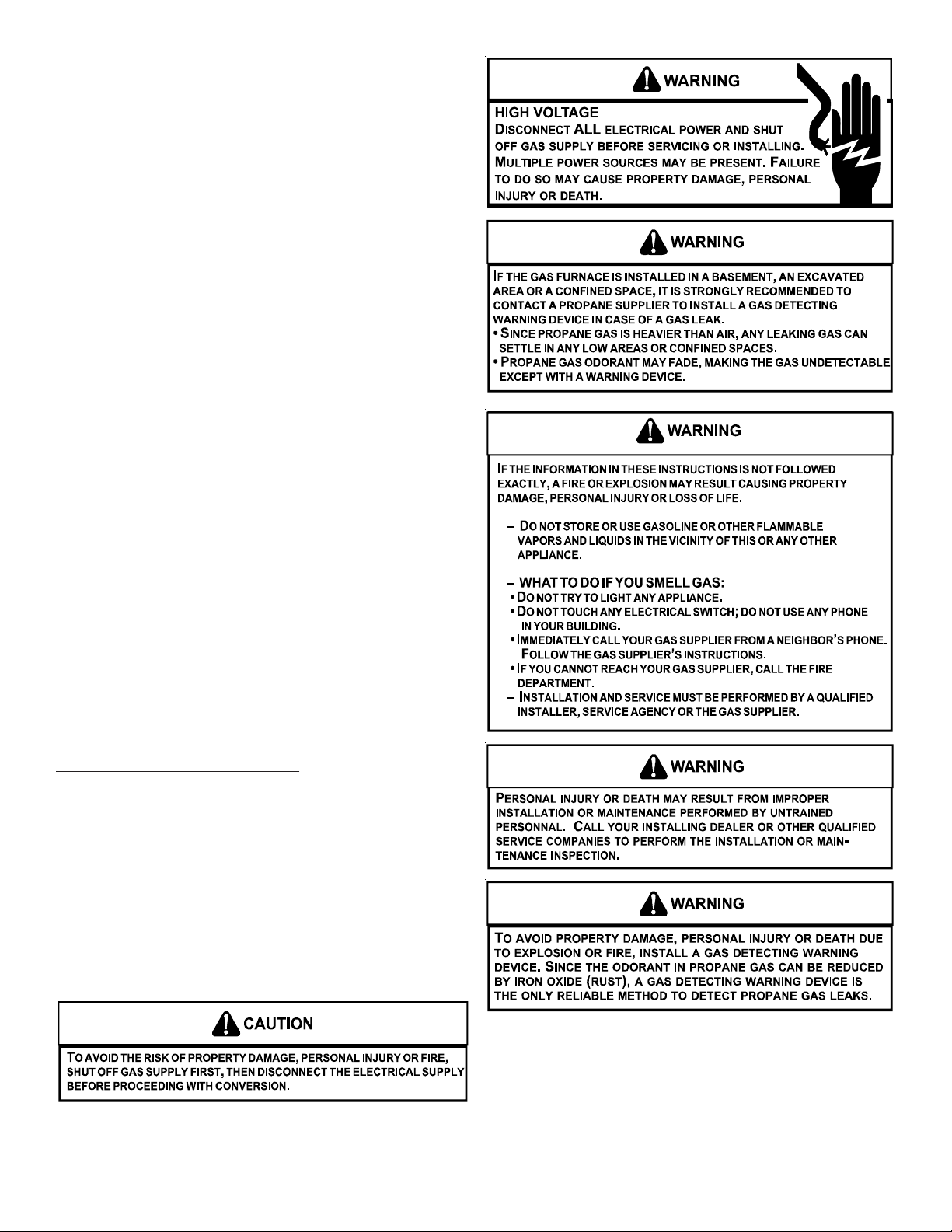
as installed in unit. Before proceeding, shut off gas supply
at manual shutoff and turn off power to unit.
Contact a local propane gas supplier
about installing a gas detecting warning device.
2
Page 3
NOTE: T o ensure proper operation, install, operate and main-
tain the unit in accordance with these installation instructions, all local building codes and ordinances. In their absence, follow the latest edition of the National Fuel Gas Code
(NFPA 54/ANSI Z223.1), and/or CAN/CSA B149.1 Installation Codes.
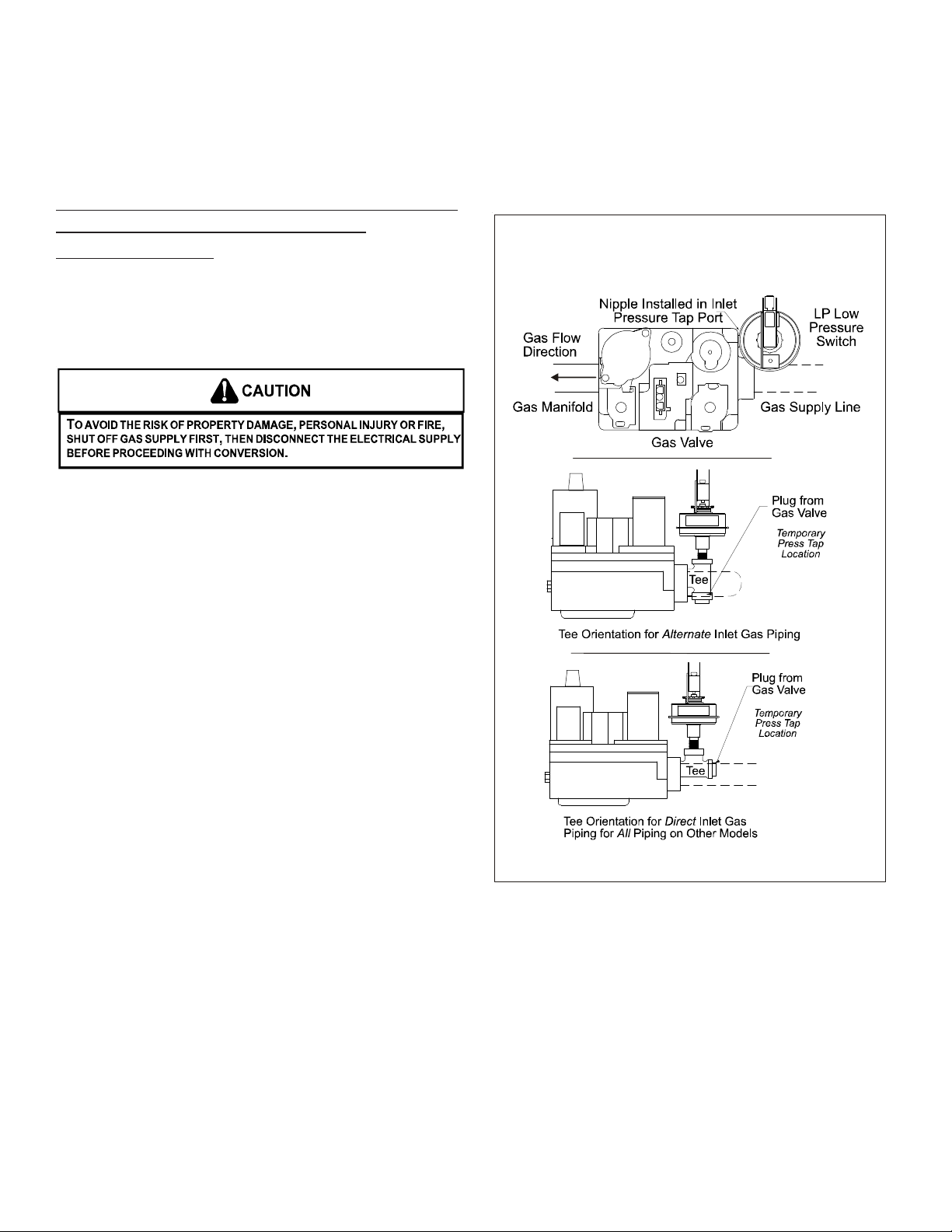
MODELS USING WHITE-RODGERS 36F & 36E
GAS V ALVES WITH 1/8” NPT INLET
PRESSURE PORT
(Alternate method on page 4 may also be used.)
NOTE: All threaded connections must be sealed with Teflon
tape or pipe dope. Pipe sealant must be approved for use
with propane gas.
1. Remove plug from the gas valve inlet pressure tap port.
Save plug.
2. Install the supplied close nipple into the open inlet pressure tap port.
3. Thread the provided tee onto free end of the nipple. Orient
the tee as shown in figure(s).
NOTE: On some models, tee orientation depends on which
side the gas supply line enters.
4. Install pressure switch into the tee.
5. Temporarily fit a field-supplied pressure tap into the remaining leg of the tee. This pressure tap will allow gas
supply line pressure measurement during installation check
out.
6. Attach the pressure tap to a manometer or pressure measurement device before opening gas supply.
7. With gas valve and manifold installed in the unit, connect
gas supply line to the gas valve.
8. Perform installation check out procedure (piping leak check,
line pressure measurement, manifold pressure adjustment,
etc.) as outlined in the unit installation instructions.
9. Turn OFF gas supply .
10. Remove field-supplied pressure tap from tee and insert plug
removed in step 1.
1 1. Turn ON gas supply and leak check inserted plug.
12. Turn OFF power to furnace. Connect jumper harness between LPLP switch and gas valve and gas valve wiring as
indicated in Figure 7 (single-stage models) or Figures 6, 8
or 9 (two-stage models).
13. Turn ON power to furnace. V erify proper unit operation.
14. Remove backing from kit label. Fold label around jumper
harness wire to indicate kit installation.
15. Adhere kit wiring diagram adjacent to existing unit wiring
diagram.
IMPORTANT NOTE: Secure all wires to avoid their contact
with any hot surfaces or moving parts.
White-Rodgers 36F Valve
White-Rodgers 36E Valve
Right Facing Gas Inlet
Figure 2
3
Page 4

White-Rodgers 36F V al ve
White-Rodgers 36E V alv e
Left Facing Gas Inlet
Figure 3
Honeywell VR82, V 9205Q Valves or
VR9205R (Mo dulating ) Valve
Used on 90%+ Models
UPFLOW
R
COUNTERFLOW
White-Rodgers 36G/36J Valve
Right Facing Gas Inlet
(Left Facing Similar)
*If there is interference with the Pressure Switch position,
rotate Pressure Switch 90 degrees.
Figure 4
Figure 5
80% MODELS USING HONEYWELL VR82,
VR9205Q OR WHITE-RODGERS 36G/36J
GAS VALVES
NOTE: All threaded connections must be sealed with Teflon
tape or pipe dope. Pipe sealant must be approved for use
with propane gas.
1. Install field-supplied 90 degree street elbow into gas valve.
2. Install field-supplied 1/2” x length required to exit wrapper
into 90 degree street elbow for left side gas outlet. Install
field supplied 1/2” x length required to exit wrapper on the
right side of the gas outlet (See Figure 6).
3. Place 1/2” tee on pipe.
4. With gas valve and manifold installed in the unit, connect
the gas supply line into 1/2” tee as required (typically opposite of gas valve side).
5. Install 1/2” x 1/8" bushing into 1/2” tee in the remaining
opening.
4
Page 5

6. Install pressure switch in bushing. Pressure switch will be
installed outside of the wrapper (see Figure 6.)
NOTE: Ensure that the switch is upright in all applications.
7. Perform installation check out procedure (piping leak check,
line pressure measurement, manifold pressure adjustment,
etc.) as outlined in the unit installation instructions.
8. Turn OFF gas supply .
9. Turn OFF power to furnace. Connect jumper harness between LPLP switch and gas valve and gas valve wiring as
indicated in Figure 7 (single-stage models - some models
may require the use of long single-stage harness) or Figures 8-1 1 (two-stage models). Some two-stage models may
require the use of long jumper wires to accommodate connection of the switch. (2nd long jumper wire can be taken
from long single stage harness.)
NOTE: Do not run wires through the gas pipe opening if
gas piping is present. Pipe could easily cause damage to
the wires.
10. Turn ON power to furnace. V erify proper unit operation.
1 1. Remove backing from kit label. Fold label around jumper
harness wire to indicate kit installation.
12. Adhere kit wiring diagram adjacent to existing unit wiring
diagram.
IMPORTANT NOTE: Secure all wires to avoid their contact
with any hot surfaces or moving parts.
Honeywell VR82 or Valves
Used on 80% Models
V 9205QR
Honeywell or White-Rodgers Gas Valves
LP Low Pressure Switch Wiring
Single-Stage Models
Gas Valve Wiring
from
Furnace Wiring
Harness
Gas Valve
Brown or Gray Wire
Single-Stage
Jumper Ha rness
White-Rodgers Valve Shown
Figure 7
White-Rodgers Gas Valve
&
Wiring Harness Connection
LP Low Pressure Switch Wiring
Two-Stage Models
Gas Valve Wiring
from
Furnace Wiring
Harness
Kit
Label
LP Low
Pressure
Switch
Figure 6
Two-Stage
Jumper Harness
Gas Valve
Figure 8
Kit
Label
LP Low
Pressure
Switch
5
Page 6

White-Rodgers Gas V alve
With Honeywell
Wiring Harness Connection
LP Low Pressure Switch Wiring
Two-Stage Models
Honeywell Gas Valv e VR9205Q
With White-Rodgers
Wiring Harness Connection
LP Low Pressure Switch Wiring
Two-Stage Models
Two-Stage
Jumper Harness
Gas Valve
Gas Valve Wiring
from
Furnace Wiring
Harness
Kit
Label
Figure 9
Honeywell Gas Valv e VR920 5Q
And
Wiring Harness Connection
LP Low Pressure Switch Wiring
Two-Stage Models
LP Low
Pressure
Switch
Two-Stage
Jumper Harness
Gas Valve Wiring
Gas Valve
from
Furnace Wiring
Harness
Kit
Label
Figure 11
LP Low
Pressure
Switch
Two-Stage
Jumper Harness
Gas Valve
Gas Valve Wiring
from
Furnace Wiring
Harness
Kit
Label
Figure 10
LP Low
Pressure
Switch
6
Page 7

SHORT 90 FURNACES USING
VR82, VR92 and 36J GAS VALVES
NOTE: All threaded connections must be sealed with
Teflon tape or pipe dope. Pipe sealant must be approved
for use with propane gas.
Gas plumbed out the r ight side
of the furnace
Gas Valve
X
Figure 13
1. Install field-supplied ½” x length required to exit wrapper , when the inlet is on left side.
2. For installing the pressure switch, in case of a right side inlet, install field-supplied ½”x 1 ½” required for “C and D” size
cabinet models. “B” cabinet models require a field supplied ½” x length sufficient enough to be clear from any interference from other components. The pressure switch can be installed within or outside the cabinet in case of right side inlet.
3. Place ½” tee on pipe.
4. With gas valve and manifold installed in the unit, connect the gas supply line into 1/2" tee as required (typically opposite
of gas valve side).
5. Install ½” x 1/8" bushing into ½” tee in the remaining opening.
6. Install pressure switch in bushing (See Figure 13).
NOTE: Ensure that the switch is upright in all applications.
7. Perform installation check out procedure (piping leak check, line pressure measurement, manifold pressure adjustment,
etc.) as outlined in the unit installation instructions.
8. Turn OFF gas supply .
9. Turn OFF power to furnace. Connect jumper harness between LPLP switch and gas valve and gas valve wiring as indicated in Figure 7 (single-stage models - some models may require the use of long single-stage harness) or Figures 8-1 1
(two-stage models). Some two-stage models may require the use of long jumper wires to accommodate connection of
the switch. (2nd long jumper wire can be taken from long single stage harness.)
NOTE: Do not run wires through the gas pipe opening if gas piping is present. Pipe could easily cause damage to the
wires.
10. Turn ON power to furnace. V erify proper unit operation.
1 1. Remove backing from kit label. Fold label around jumper harness wire to indicate kit installation.
12. Adhere kit wiring diagram adjacent to existing unit wiring diagram.
IMPORTANT NOTE: Secure all wires to avoid their contact with any hot surfaces or moving parts.
Gas plumbed out the l eft side
of the furnace
Gas Valve
X
7
Page 8

®
TROUBLESHOOTING
If the furnace fails to light after installation of the LP low pressure switch kit, proceed as follows:
Remove jumper harness
from gas valve and gas
valve wiring.
Reconnect furnace wiring
harness to gas valve.
Problem does not
involve the LP low
pressure switc h.
With gas supply on,
measure resistance
between terminals of LP
low pressure switch.
Are
switch contacts
closed?
Check jumper harness
circuits fo r continuity.
NO
Reconnect LP low
pressure switch jumper
harness.
Check gas supply
gas val ve wiring, etc.
NO NO
Is line
pressure above
9.0" w.c.?
Replace faulty LP low
pressure switch.
Reconnect jumper
harness.
Correct insufficient ga s
line pressure problem.
Reconnect jumper
harness.
Continuity
checks OK on
jumper harness?
NO
Jumper ha rness pro blem.
Reconnect jumper
harness . Chec k jump er
harness connections.
NOTE: SPECIFICATIONS AND PERFORMANCE DATA LISTED HEREIN ARE SUBJECT TO CHANGE WITHOUT NOTICE
Visit our website at www.daikincomfort.com, www.goodmanmfg.com or www.amana-hac.com for information on:
• Products • Parts • Customer Services
• Warranties • Financing Options • Contractor Programs and Training
Goodman Manufacturing Company, L.P.
5151 San Felipe, Suite 500, Houston, TX 77056
© 2012 - 2014 Goodman Manufacturing Company, L.P.
is a trademark of Maytag Corporation and is used under license. All rights reserved.
8
 Loading...