

Page 1

LAKT01 & LAKT03
LOW AMBIENT KITS
INSTALLATION INSTRUCTIONS
ATTENTION INSTALLING PERSONNEL
As a professional installer you have an obligation to know the product better than the customer. This includes all safety precautions
and related items.
Prior to actual installation, thoroughly familiarize yourself with this
Instruction Manual. Pay special attention to all safety warnings.
Often during installation or repair it is possible to place yourself in
a position which is more hazardous than when the unit is in operation.
Remember, it is your responsibility to install the product safely
and to know it well enough to be able to instruct a customer in its
safe use.
Safety is a matter of common sense...a matter of thinking before
acting. Most dealers have a list of specific good safety practices...
follow them.
The precautions listed in this Installation Manual are intended as
supplemental to existing practices. However, if there is a direct
conflict between existing practices and the content of this manual,
the precautions listed here take precedence.
DESCRIPTION
The LAKT01 and LAKT03 low ambient kits (for Light Commercial
Models and Residential Splits) are temperature sensitive fan motor speed controls designed to regulate the outdoor section head
pressure by varying the air volume through the outdoor coil and
are required when operating below 55
is achieved by sensing the liquid temperature at the coil by means
of a thermistor probe. The probe provides an input signal to the
control to increase the fan motor speed in relation to changes in
the liquid temperature. Ensure all parts are included before beginning. If parts are missing from the kit contact the distributor where
the kit was purchased.
NOTE: These kits are not approved for any 16 and 18 SEER outdoor units that utilize an ECM condenser fan motor.
°
F outdoor temperature. This
The following accessories must be installed on all condensers and
remote heat pumps when equipped with low ambient kits.
1. Crankcase heater must be installed if not factory installed.
2. Hard start kit for single phase units. (See Spec Sheet for
Accessories)
3. TXV kit installed on indoor evaporator coil, if not factory installed.
4. FSK01A - Freeze protection kit must be installed on indoor
coil.
o
5. Wind buffer must be installed for temperatures below 0
areas with high prevailing winds. Wind buffer can be a wall
fabricated from wood or masonry material that will prevent
the prevailing wind from causing the outdoor fan to rotate.
NOTE: When wind buffer is installed, it is necessary to use
minimum 4" risers to elevate the unit off of the pad to provide
better airflow for moderate and high ambient temperatures.
F or
NOTE: SPECIFICATIONS AND PERFORMANCE DATA LISTED HEREIN ARE SUBJECT TO CHANGE WITHOUT NOTICE
Quality Makes the Difference!
All of our systems are designed and manufactured with the same high quality standards regardless of size or
efficiency. We have designed these units to significantly reduce the most frequent causes of product failure.
They are simple to service and forgiving to operate. We use quality materials and components. Finally, every
unit is run tested before it leaves the factory. That’s why we know. . .There’s No Better Quality.
Visit our website at www.daikincomfort.com, www.goodmanmfg.com or www.amana-hac.com for information on:
• Products • Parts
• Warranties • Contractor Programs and Training
• Customer Services • Financing Options
IO-826
7/2014
is a registered trademark of Maytag Corporation or its related companies and is used under license to
© 2014 Goodman Manufacturing Company, L.P.
Goodman Company, L.P., Houston, TX, USA. All rights reserved.
Page 2
PARTS LIST FOR KITS
Item Part No. Qty.
Pres sure Control & Probe LAKT01 0130M00058 1
Pres sure Control & Probe LAKT03 0130M00059 1
Wire As sembly LAKT01 --- 8
Wire As sembly LAKT03 --- 6
Terminals LAKT01 --- 4
Terminals LAKT03 --- 7
Wire Ties LAKT01 --- 3
Wire Ties LAKT03 --- 4
Mount ing Bracket
LAKT01 & LAKT03
0121M00047 1
Inst allation Instruc tions IO-826 1
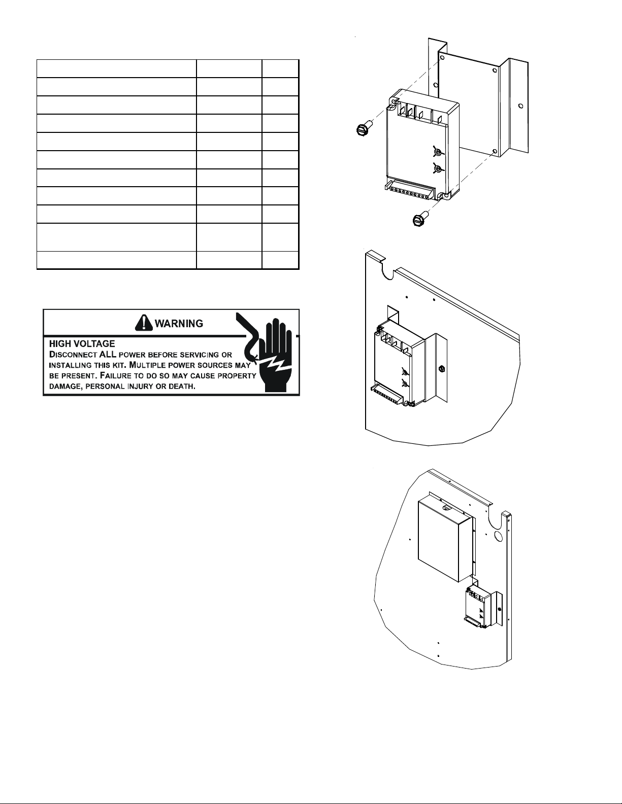
KIT INSTALLATION
Figure 1A
1. Disconnect all sources of power to the unit.
2. Remove access panels to blower compartment and control
box.
3. Using the screws provided, secure the control to the mounting bracket provided (see Figure 1A). Secure the new assembly on the condenser evaporator partition panel in the
blower section of the unit.
For 3 to 12.5 ton light commercial, secure 2 inches below
the hole where the fan and compressor leads exit the blower
section. See Figure 1B.
For 15 to 20 ton light commercial, secure to the right of
the capacitor assembly, located on the partition panel. See
Figure 1C.
For residential 3 phase models, secure ICM to the control
panel. See Figure 1D. (Do not use mounting bracket in this
application.)
NOTE: Do not install the control in areas where the mounting screws can come into contact with the condenser coil or
tubing.
Figure 1B
Figure 1C
2
Page 3
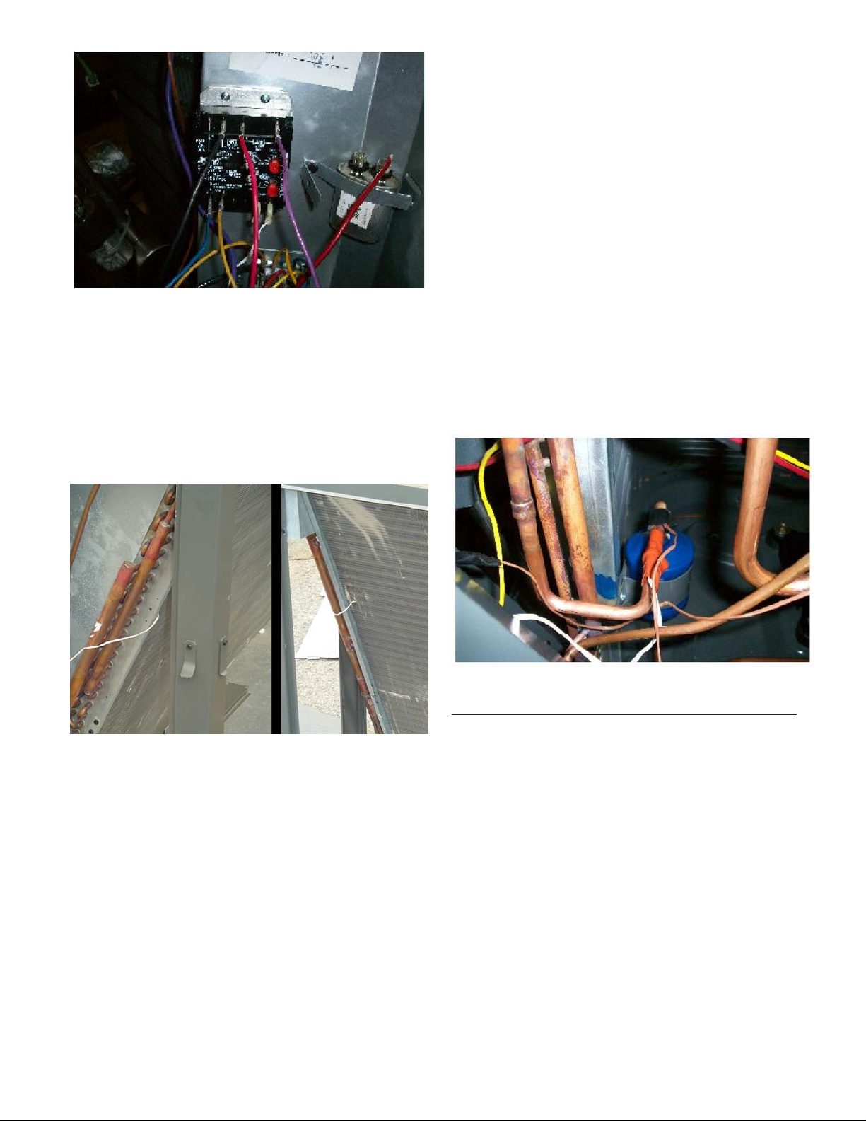
Figure 1D
4. Connect the electrical wiring as shown in the wiring diagrams
on pages 5 - 8.
5. For light commercial, install temperature probe between
the fins, at the middle to upper section of the condenser coil
(see Figure 2).
For Residential Split Condensers and heat pumps,
install the probe on the liquid line before the filter/dryer.
Ensure the probe body is completely attached to the body of
the liquid tube before securing with the tape (See Figure 3).
LAKT01 (3 thru 6 tons)
Wiring Diagram 0140M00108 - use with AC and HP units, three
phase and single phase application.
For residential 3 phase condensers, connect wires per 0140M00108
wiring diagram.
For residential 3 phase heat pumps, connect wires per 0140R00167
wiring diagram.
LAKT03 (7 ½ tons thru 12 ½ tons)
Wiring Diagram 0140L03520A - use with AC and HP units, three
phase application.
LAKT03 (15 tons and up)
Wiring Diagram 0140L01008 - use with AC units.
(a) Wiring diagrams show the controller connection for 120/
277 volts supply. For 480/600 volts application, connect
the power supply leads to the 480/600 VAC terminal.
NOTE: The low ambient kit is pre-set at the factory and re-
quires no further adjustment. Altering the setting may
greatly reduce motor life.
Figure 2
6. Connect the probe leads to the terminal marked PROBE S1.
For systems with multiple refrigeration circuits, attach the
second probe to PROBE S2 or PROBE S3. The LAKT03 is
shipped with two probes. See control instruction manual for
multiple probe connection and operation.
WIRING DIAGRAMS AND APPLICATION
The LAKT01 and LAKT03 kits are shipped with wiring diagram
included. Affix the low ambient kit wiring diagram on the control
box door next to the unit wiring diagram.
Figure 3
WIRING PROCEDURE FOR LAKT01 (REMOTE AC & HP):
1. Connect the wiring as shown on page 6.
2. Attach supplied wiring diagram adjacent to existing wiring
diagram. Follow the system calibration instruction provided
in the control instruction manual for sleeve bearing motors.
Verify wiring is correct.
3. Use provided wire ties to secure wire leads away from all
moving parts and warm refrigeration tubing.
4. Reinstall access panel.
5. Restore power and verify system operation.
3
Page 4

WIRING PROCEDURE FOR LAKT03 (7½ thru 12 ½ tons):
WIRING PROCEDURE FOR LAKT03 (15 tons & up):
1. Find the three (3) fan motor leads (purple, black & brown)
from condenser motor circuit #2. (These leads pass through
the partition panel just above the area where the controller
is mounted.) Disconnect the leads at the junctions.
2. From the kit, install one of the “Y” push-on terminal adapters onto the controller terminal marked Motor 2 and another
onto terminal Line 1/Motor 1.
NOTE: Make sure the correct voltage tap is selected.
3. Connect the black wire from condenser motor circuit #2 to
one side of the connector on the Motor 2 terminal of the
controller. Using the male/female black adapter wire from
the kit, connect the black wire coming from the control box to
the Line 2 terminal on the controller.
4. Connect the male/female purple adapter wire from the kit to
the purple wire coming from the control box and to one side
of the Line 1/Motor 1 terminal on the controller.
5. Find the three fan motor leads (purple, black & brown) going
to condenser motor circuit #1. (These leads exit through the
partition panel on the opposite side of the controller.) Cut
the black and purple wires so that those leads will connect
to the controller. Attach the provided terminals to each of the
leads and connect the purple lead to the Line 1/Motor 1
terminal. Attach the black wire to the other side of the “Y”
push-on terminal adapters on the Motor 2 terminal on the
controller.
6. Remove or tape up the ends of the cut purple and black
wires.
7. Locate the red wire connecting FC1 (fan capacitor #1) to T2
of the compressor contactor #1. Disconnect the wire from
T2 and connect it to the terminal on FC2 (fan capacitor #2)
that has three black wires. Remove the black wire from FC1
(fan capacitor #1) and connect to T2 of the compressor
contactor 1.
1. Remove the cover on the capacitor assembly that is located
next to the controller. Disconnect the red and black leads
that are coming form the control box assembly. They are
connected to the furthest right capacitor and the terminal
block respectively.
2. From the kit, install one of the Y push on terminal adapters
onto the controller terminal marked Line 1 / Motor 1.
3. Connect the disconnected black wire to Line 2 terminal on
the controller. Connect the disconnected red wire onto one
of the Y push on terminals now located on the Line 1 / Mo-
tor 1 terminal of the controller.
4. From the kit, connect the red wire between the remaining Y
terminal on Line 1 / Motor 1 and the location on the furthest
right capacitor where the red wire had previously been removed.
5. From the kit, connect the black wire between the Motor 2
terminal on the controller and the terminal block where the
black wire had previously been removed.
6. Connect the blue wire and the yellow wire to the controller on
the 24 VAC connection as shown on the diagram.
7. Route wires along tubing, under evaporator, and into the
bottom opening of control box. Connect the yellow wire to
Y1 on the low voltage terminal strip and the blue wire to C.
8. Attach supplied wiring diagram adjacent to existing wiring
diagram. Follow the system calibration instruction provided
in the control instruction manual for sleeve bearing motors.
Verify wiring is correct.
9. Use provided wire ties to secure wire leads away from all
moving parts and warm refrigeration tubing.
10. Reinstall access panel.
11. Restore power and verify system operation.
8. Connect YL and BL wire to 24 vac connection on the controller and then to YI and C respectively, on the terminal block
in the control box.
9. Attach supplied wiring diagram adjacent to existing wiring
diagram. Follow the system calibration instruction provided
in the control instruction manual for sleeve bearing motors.
Verify wiring is correct.
10. Use provided wire ties to secure wire leads away from all
moving parts and warm refrigeration tubing.
11. Reinstall access panel.
12. Restore power and verify system operation.
4
Page 5

WIRING DIAGRAM
WARNING
LAKT01
CONNECT PARALLEL TO
REVER SING VALVE 24 VAC
( IF USED ) SEE NOTE 2
O.D. MOTOR
( IF USED )
SEE NOTE 3
MODELS: GSX**090*, GSX**120*, DX**090*,
DX**120* & DC*036-072
YL
VAC
PUMP
S1
S2
S3
BR
N.C. HEAT PUMP
24
HEAT
PROBE
PROBE
START
HARD
PROBE
BK
SPEED
CONTROLS
CUT OUT
RD
ICM
FULL
SPEED
VAR IABL E
SPPED
PU
L
I
N
480-600
VAC
E
1
/
M
120-277
VAC
O
T
O
R
1
10 AMP
MAX
MOTOR 2LINE 2
BK
PU
FAN
RUN
CAPACITOR
T2 L2
T1
RD
COMP
BK
COMP
HERM
C
CONNECT TO TERMINAL BLOCK
Y (CALL FOR COOL)
BL (COMMON)
C
L1
LEGEND
RETURN BEND END
OF CONDENSER COIL
RD RED
BK BLACK
PU PURPLE
BR BROWN
CONTACTOR
B BLUEL
NOTES:
1. USE COPPER CONDUCTORS ONLY.
SENSOR
2. ALTERNATE WIRING FOR HEAT PUMP APPLICATION, MAKE A
PARALLEL CONNECTION FROM THE REVERSING VALVE 24 VAC
POWER SUPPLY TO THE HEAT PUMP TERMINALS ON THE CONTROL.
THE SELECT JUMPER MUST BE IN THE NORMALLY CLOSED
POSITION FOR NON-ENERGIZED REVERSING VALVE DURING HEATING.
3. ALTERNATE WIRING FOR SINGLE PHASE APPLICATION; THREE PHASE
MODELS DOES NOT REQUIRE A DUAL RUN CAPACITOR.
4. WIRING DIAGRAM SHOWS CONTROLLER CONNECTION FOR 120 TO
277 VOLTS SUPPLY; FOR 480-600 VOLT APPLICATION,
CONNECT POWER SUPPLY BETWEEN LINE 2 AND THE 480-600
VAC TERMINALS.
0140M00 108 REV B
Wiring is subject to change, always refer to the wiring diagram on the unit for the most up-to-date wiring.
5
Page 6

WIRING DIAGRAM
WARNING
DEFRO ST BOARD
LVDR
W2
O O R R
C Y
OR
BK
RD COMP
BK COMP
BK
BK
RD
T2
T3
T1
L1
L2
L3
CONTACTOR
DF2
H
V
D
R
DF1
DFT
REVERSING VALVE
BK
MODELS: GSZ**090* & GSZ**120*
DZ**090* & DZ**120*
BK
BK
BK
BK
ICM
PU
PU
HERM
FAN
C
CAPACITOR
RD
PU
2
LOAD
X
X
BR
PU
OD FAN MOTOR
CUT OUT TEMP
HARD START
LAKT01
BK
24V
HP
YL
BL
BK
OR
CONNECT PARALLEL TO
24V REVERSING VALVE
FIGURE 3
SENSOR
NOTE
1. THE HEAT PUMP TERMINALS ACCEPT THE 24VAC SIGNAL FROM
THE RV HOLDING COIL . MAKE PARALLEL CONNECTION FROM RV
TO HP TERMINALS.
2. THE HEAT PUMP SELECT JUMPER WIRE MUST BE IN THE ( N.C.)
POSITION.
3. ENSURE THE BODY OF THE SENSOR PROBE IS COMPLETELY
ATTACHED TO THE BODY OF LIQUID TUBE BEFORE SECURING
WITH THE TAPE.
4. USE COPPER CONDUCTORS ONLY.
5. WIRING DIAGRAM SHOWS CONTROLLER CONNECTION FOR 120 TO 277 VOLTS SUPPLY.
FOR 480-600 VOLT APPLICATION, CONNECT POWER SUPP LY BETWEEN
LINE 2 AND THE 480-600VAC TERMINALS.
LIQUID LINE
BEFORE
FILTER DRIER
CONNECT WITH
BL
YL (CALL FOR COOL )
YL
BL ( COMMON)
T-STAT L EADS
RETURN BEND END
OF CONDENSER COIL
( OR )
FILTER DRIER
LEGEND
RD RED
BK BLACK
PU PURPLE
BR BROWN
YL YELLOW
BL BLUE
OR ORANGE
0140R00167
Wiring is subject to change, always refer to the wiring diagram on the unit for the most up-to-date wiring.
6
Page 7

WIRING DIAGRAM
WARNING
BK
BK
BK
YL
YL
YL
BK
BK
BK
BL
BL
BL
MODELS: DC*090 - DC*150
MODELS: DC*090 - DC*150
MODELS: DC*090 - DC*150
VAC
VAC
VAC
24
24
24
PUMP
PUMP
PUMP
HEAT
HEAT
HEAT
PROBE
PROBE
PROBE
S1
S1
S1
PROBE
PROBE
PROBE
S2
S2
S2
PROBE
PROBE
PROBE
S3
S3
S3
O.D. MOTOR
O.D. MOTOR
O.D. MOTOR
N.C. HEAT PUMP
N.C. HEAT PUMP
N.C. HEAT PUMP
START
START
START
HARD
HARD
HARD
BK
BK
BK
BR
BR
BR
FAN
FAN
FAN
RUN
RUN
RUN
CAPACITOR
CAPACITOR
CAPACITOR
CUT OUT
SPEED
CUT OUT
SPEED
CUT OUT
SPEED
C
C
C
ICM
ICM
ICM
CONTROLS
CONTROLS
CONTROLS
USE ONE TERMINAL ONLY
480-600
VAC
480-600
VAC
480-600
VAC
LINE 1 / MOTOR 1
VAC
VAC
VAC
120-277
120-277
120-277
LINE 2
LINE 2
LINE 2
FULL
SPEED
FULL
SPEED
FULL
SPEED
10 AMP
MAX
10 AMP
MAX
10 AMP
MAX
VARIABLE
SPPED
VARIABLE
SPPED
VARIABLE
SPPED
MOTOR 2
MOTOR 2
MOTOR 2
PU
PU
PU
SEE NOTE 2
PU
PU
PU
PU
PU
PU
RD
RD
RD
BK
BK
BK
PU
PU
PU
BK
BK
BK
BK
BK
BK
O.D. MOTOR
O.D. MOTOR
O.D. MOTOR
BR
BR
BR
RUN
RUN
RUN
CAPACITOR
CAPACITOR
CAPACITOR
C
C
FAN
FAN
FAN
C
RD
RD
RD
CONTACTOR
CONTACTOR
CONTACTOR
LAKT03
BK
BK
BK
O (HEAT PUMP ONLY)
O (HEAT PUMP ONLY)
C (HEAT PUMP ONLY)
C (HEAT PUMP ONLY)
T1 T2
T1 T2
T1 T2
L1 L2
L1 L2
L1 L2
CONNECT TO TERMINAL BLOCK
Y1 (CALL FOR COOL)
CONNECT TO TERMINAL BLOCK
Y1 (CALL FOR COOL)
C (COMMON)
C (COMMON)
SENSOR
SENSOR
SENSOR
CIRCUIT #1
CIRCUIT #1
CIRCUIT #1
RD
RD
RD
T1
T1
T1
L1
L1
L1
CMC
CMC
CMC
T2
T2
T2
L2
L2
L2
HEAT
PUMP ONLY
(SEE NOTE "2")
INSERT PROBE 2/3
INSERT PROBE 2/3
INSERT PROBE 2/3
UP IN FIN PACK ON
UP IN FIN PACK ON
SENSOR
SENSOR
SENSOR
CIRCUIT #2
CIRCUIT #2
CIRCUIT #2
UP IN FIN PACK ON
HEADER END OF
HEADER END OF
HEADER END OF
COIL
COIL
COIL
NOTES:
1. USE COPPER CONDUCTORS ONLY.
2. ALTERNATE WIRING FOR HEAT PUMP APPLICATION, CONNECT
TO THE HEAT PUMP TERMINALS ON THE CONTROL.
THE SELECT JUMPER MUST BE IN THE NORMALLY CLOSED
POSITION FOR NON-ENERGIZED REVERSING VALVE DURING HEATING.
PURPLE WIRE IS CONNECTED TO T1 OF CMC, AND NOT TO C TERMINAL
OF CAPACITOR.
3. WIRING DIAGRAM SHOW S CONTROLLER CONNECTION FOR 120 TO
277 VOLTS SUPPLY; FOR 480-600 VOLT APPLICATION,
CONNECT POWER SUPPLY BETWEEN LINE 2 AND THE 480-600
VAC TERMINALS.
T3
T3
T3
L3
L3
C
C
C
LEGEND
LEGEND
LEGEND
RD RED
RD RED
RD RED
BK BLACK
BK BLACK
BK BLACK
PU PURPLE
PU PURPLE
PU PURPLE
BR BROWN
BR BROWN
BR BROWN
YL YELLOW
YL YELLOW
YL YELLOW
BL BLUE
BL BLUE
BL BLUE
L3
0140L03520-A
0140L03520-A
0140L03520-A
Wiring is subject to change, always refer to the wiring diagram on the unit for the most up-to-date wiring.
7
Page 8

WIRING DIAGRAM
WARNING
CONNECT PARALLEL TO
REVERSING VALVE 24 VAC
( IF USED ) SEE NOT E 2
LAKT03
L2L1
L2L1
L3
N.C. HEAT PUMP
VAC
24
PUMP
HEAT
PROBE
S1
PROBE
S2
START
HARD
PROBE
S3
ICM
CONTROLS
CUT OU T
SPEED
SPEED
SPPED
L
I
480-600
VAC
N
E
1
/
120-277
VAC
M
O
T
O
R
1
FULL
10 AMP
MAX
VARIA BLE
MOTOR 2LINE 2
RD
CC2
RD
BK
CC1
RD
L3
T2T1
T3
T2T1
T3
RD
L2L1
L3
RD
T2T1
T3
SENSOR
SENSOR
CIRCUIT #2
CIRCUIT #1
CONNECT TO TERMINAL BLOCK
Y (CALL FOR COOL)
BL (COMMON)
INSERT PR OBE 2/3
UP IN FIN PACK ON
HEADER END OF
COIL
BK
PU
BR
PU PU
BR BR
PU
PU
PU
BR
BR
BR
PU
PU
BR
BR
FC1
FC2
FC3
TB2
CM3
CM2
CM1
C
RD
F
C
RD
F
C
F
BK
BK
BK
BK
BK
BK
BK
LEGEND
RD RED
BK BLACK
PU PURPLE
BR BROWN
YL YELLOW
BL BLUE
NOTES:
1. USE COPPER CONDUCTORS ONLY.
2. ALTERNATE WIRING FOR HEAT PUMP APPLICATION, MAKE A
PARALLEL CONNECTION FROM THE REVERSING VALVE 24 VAC
POWER SUPPLY TO THE HEAT PUMP TERM INALS ON THE CONTROL.
THE SELECT JUMPER MUST BE IN THE NORMALLY CLOSED
POSITION FOR NON-ENERGIZED REVERSING VALVE DURING HEATING.
3. WIRING DIAGRAM SHOWS CONTROLLER CONNECTION FOR 120 TO
277 VOLTS SUPPLY; FOR 480-600 VOLT APPLICATION,
CONNECT POWER SUPPLY BETWEEN LINE 2 AND THE 480-600
VAC TERMINALS.
0140L 01008 REV B
Wiring is subject to change, always refer to the wiring diagram on the unit for the most up-to-date wiring.
8
 Loading...