

Page 1
I
NSTALLATION INSTRUCTIONS
C
OMMERCIAL
H
EATING
& C
F
OR
OOLING
3 T
ON
- 6 T
ON
P
CPG S
ACKAGE
ERIES
G
AS
U
C
NIT
®
US
This Forced Air Central Unit Design Complies With
Requirements Embodied in The American National
Standard / National Standard of Canada Shown
Below.
ANSI Z21.47•CSA-2.3 Central Furnaces
RECOGNIZE THIS SYMBOL AS A SAFETY PRECAUTION.
ATTENTION INSTALLING PERSONNEL
Prior to installation, thoroughly familiarize yourself with this Installation Manual. Observe all safety warnings.
During installation or repair, caution is to be observed.
It is your responsibility to install the product safely and to educate the customer on its safe use.
All information contained herein is subject to change without notice.
Goodman Manufacturing Company, L.P .
IO-353C 5151 Felipe, Suite 500, Houston, TX 77056
11/10 www.goodmanmfg.com www.amana-hac.com
© 2009-2010 Goodman Manufacturing Company, L.P.
Page 2
Index
REPLACEMENT PARTS
Replacement Parts ........................................................2
Safety Instructions ........................................................2
General Information ......................................................3
Unit Location ................................................................. 4
Clearances .....................................................................5
Roof Curb Post-Installation Checks ............................ 6
Roof Top Duct Connections .........................................6
Rigging Details ..............................................................7
Electrical Wiring ............................................................9
Gas Supply Piping.......................................................10
Propane Gas Installations ..........................................12
Circulating Air and Filters...........................................13
Venting ......................................................................... 13
Condensate Drain Connection ...................................13
Startup, Adjustment s, and Checks ............................14
Normal Sequence Of Operation ................................. 19
Troubleshooting ..........................................................20
Input Rating .................................................................21
Air flow Adjustments................................................... 22
ORDERING PARTS
When reporting shortages or damages, or ordering repair
parts, give the complete unit model and serial numbers
as stamped on the unit’s nameplate.
Replacement parts for this appliance are available
through your contractor or local distributor. For the
location of your nearest distributor, consult the white
business pages, the yellow page section of the local
telephone book or contact:
CONSUMER AFFAIRS
GOODMAN MANUFACTURING COMPANY, L.P.
7401 SECURITY WAY
HOUSTON, TEXAS 77040
(877) 254-4729
SAFETY INSTRUCTIONS
TO THE INSTALLER
Before installing this unit, please read this manual to
familiarize yourself on the specific items which must be
adhered to, including maximum external static pressure
to unit, air temperature rise, minimum or maximum CFM
and motor speed connections.
Keep this literature in a safe place for future reference.
WARN ING
Motor Sheave Adjustments ........................................ 22
Maintenance ................................................................22
Appendix A Blower Performance Tables................... 25
Direct Drive .............................................................. 25
CPG036 Down Shot and Horizontal...................25
CPG048 Down Shot and Horizontal...................26
CPG060 Down Shot............................................. 27
CPG060 Horizontal ..............................................28
Belt Drive ................................................................. 29
Standard Down Shot...........................................29
Standard Horizontal ............................................30
High Static Down Shot........................................31
Belt Drive - High Static Horizontal ..................... 32
Appendix B Electrical Data......................................... 33
Appendix C Unit Dimensions ..................................... 34
Appendix D Wiring Diagrams .....................................35
IF
THE INFORMATION IN THESE INSTRUCTIONS IS NOT FOLLOWED
EXACTLY, A FIRE OR EXPLOSION MAY RESULT CAUSING PROPERTY
DAMAGE, PERSONAL INJURY OR LOSS OF LIFE
- D
O NOT STORE OR USE GASOLINE OR OTHER FLAMMABLE VAPORS
AND LIQUIDS IN THE VICINITY OF THIS OR ANY OTHER APPLIANCE
- WHAT T O D O IF YO U SMELL GA S:
- I
* D
O NOT TRY TO LIGHT ANY APPLIANCE
O NOT TOUCH ANY ELECTRICAL SWITCH; DO NOT USE
* D
ANY PHONE IN YOUR BUILDING
* I
MMEDIATELY CALL YOUR GAS SUPPLIER FROM A
NEIGHBORS PHONE
INSTRUCTIONS
* I
F YOU CANNOT REACH YOUR GAS SUPPLIER, CALL THE
NSTALLATION AND SERVICE MUST BE PERFORMED BY A QUALIFIED
INSTALLER, SERVICE AGENCY OR THE GAS SUPPLIER
FIRE DEPARTMENT
. F
OLLOW THE GAS SUPPLIERS
.
.
.
.
.
.
WARNING
SHOULD OVERHEATING OCCUR OR THE GAS SUPPLY FAIL TO SHUT OFF, TURN
OFF THE MANUAL GAS SHUTOFF VALVE EXTERNAL TO THE FURNACE BEFORE
TURNING OFF THE ELECTRICAL SUPPLY.
CAUTION
S
HEET METAL PARTS, SCREWS, CLIPS AND SIMILAR ITEMS INHERENTLY
HAVE SHARP EDGES, AND IT IS NECESSARY THAT THE INSTALLER AND
SERVICE PERSONNEL EXERCISE CAUTION
.
2
Page 3
WARN ING
DO
NOT CONNECT TO OR USE ANY DEVICE THAT IS NOT DESIGN
CERTIFIED BY GOODMAN FOR USE WITH THIS UNIT
PROPERTY DAMAGE, PERSONAL INJURY, REDUCED UNIT
PERFORMANCE AND
FROM THE USE OF SUCH NON-APPROVED DEVICES
/OR
HAZARDOUS CONDITIONS MAY RESULT
. S
.
ERIOUS
WARNING
HIS PRODUCT CONTAINS OR PRODUCES A CHEMICAL OR CHEMICALS WHICH
T
MAY CAUSE SERIOUS ILLNESS OR DEATH AND WHICH ARE KNOWN TO THE
S
TATE OF CALIFORNIA TO CAUSE CANCER, BIRTH DEFECTS OR OTHER
REPRODUCTIVE HARM.
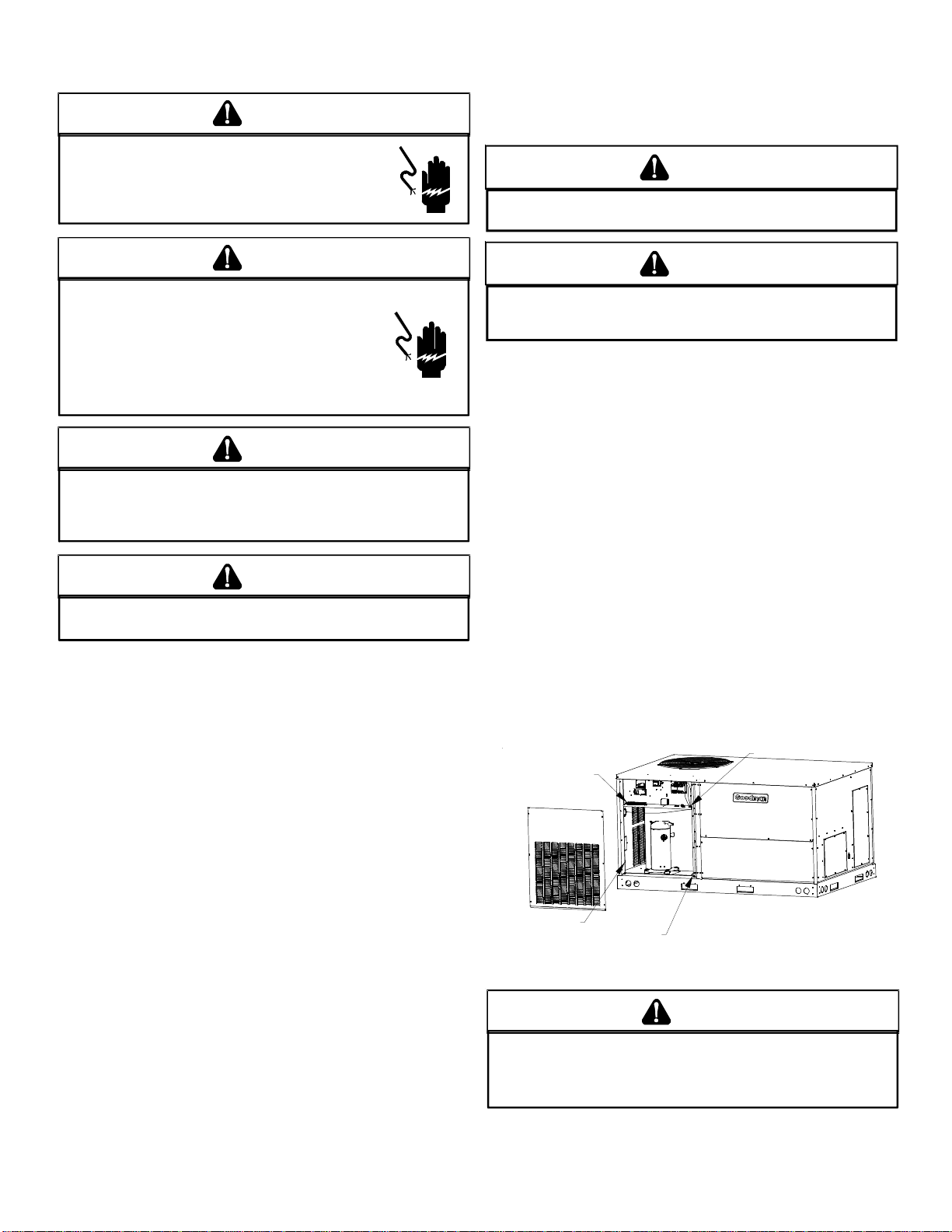
WARNING
WARNING
CARBON MONOXIDE POISONING
HAZARD
FAILUR E TO KEEP THIS CO MPARTMENT CLOS ED
EXCEPT WHEN SERVICING COULD RESULT IN
CARBON MONOXIDE POISONING OR DEATH.
THIS COMPARMENT MUST BE CLOSED EXCEPT
WHEN SERVICING
A VERTISSEMENT
RISQUE D'EMPOISONNEMENT AU
MONOXYDE DE CARBONE
SI CE COMPARTMENT N'EST PAS FERME EN
TOUT TEMPS, SAU F EN CAS D E REPARATION, IL Y
A RISQUE D'EM POISONNEME NT OU MONOXYDE
DE CARBON E OU DE MORT.
CE COMPARTIMENT DO IT ETRE FE RME SAUF AU
MOMENT DE L'ENTRETIEN.
O AVOID PROPERTY DAMAGE, PERSONAL INJURY OR DEATH, DO NOT USE
T
I
THIS UNIT IF ANY PART HAS BEEN UNDER WATER.
QUALIFIED SERVICE TECHNICIAN TO INSPECT THE FURNACE AND TO REPLACE
ANY PART OF THE CONTROL SYSTEM AND ANY GAS CONTROL HAVING BEEN
UNDER WATER.
T
HIS UNIT MUST NOT BE USED AS A "CONSTRUCTION HEATER
DURING THE FINISHING PHASES OF CONSTRUCTION ON A NEW
STRUCTURE
FAILURE OF THE UNIT DUE TO EXTREMELY LOW RETURN AIR
TEMPERATURE AND EXPOSURE TO CORROSIVE OR VERY
DIRTY
. T
HIS TYPE OF USE MAY RESULT IN PREMATURE
ATMOSPHERES
.
MMEDIATELY CALL A
"
WARN ING
HIGH VOLTAGE!
ISCONNECT ALL POWER BEFORE SERVICI NG OR
D
INSTALLING THIS UNIT
BE PRESENT
DAMAGE, PERSONAL INJURY OR DEATH
. F
. M
AILURE TO DO SO MAY CAUSE PROPERTY
ULTIPLE POWER SOURCES MAY
.
WARNING
TO PREVENT THE RISK OF PROPERTY DAMAGE, PERSONAL INJURY, OR DEATH,
DO NOT STORE COMBUSTIBLE MATERIALS OR USE GASOLINE OR OTHER
FLAMMABLE LIQUI DS OR VAPORS I N THE V ICINIT Y OF THI S APPL IANCE.
ADVERTENCIA
PELIGRO MONOXIDO DE CARBONO
TOXICO
EL FRACASO DE NO MANTENER
COMPARTIMIENTO CERRADO MENOS DURANTE,
ATENDER, PODRIA TENER COMO RESULTADO
ENVENENAR DE MONOXIDO DE CARBONO O
MUERTE.
ESTE COMPARTIMIENTO DEBE CERRADO MENOS
AL A TEN DER
GENERAL INFORMA TION
WARNING
O PREVENT PROPERTY DAMAGE, PERSONAL INJURY OR DEATH, DUE TO FIRE,
T
EXPLOSIONS, SMOKE, SOOT, CONDENSATION, ELECTRIC SHOCK OR CARBON
MONOXIDE, THIS UNIT MUST BE PROPERLY INSTALLED, REPAIRED, OPERATED,
AND MAINTAINED.
This unit is approved for outdoor installation ONLY. To
assure that your unit operates safely and efficiently, it must
be installed, operated, and maintained in accordance with
these installation and operating instructions, all local building
codes and ordinances, or in their absence, with the latest
edition of the National Fuel Gas Code NFP A54/ANSI Z223.1
and National Standard of Canada CAN/CSA B149 Installation Codes.
-
0140L00106
WARN ING
HIGH VOLTAGE!
INSTALLATION AND REPAIR OF THIS UNIT SHOULD BE
PERFORMED
REQUIREMENTS OF AN
SPECIFIED BY THE AIR CONDITIONING AND
R
EFRIGERATION INSTITUTE
INSTALL OR REPAIR THIS UNIT WITHOUT SUCH
BACKGROUND MAY RESULT IN PRODUCT DAMAGE
PERSONAL INJURY OR DEATH
ONLY BY
INDIVIDUALS MEETING THE
“E
NTRY LEVEL TECHNICIAN” AS
(ARI). A
TTEMPTING TO
.
,
The heating and cooling capacities of the unit should be
greater than or equal to the design heating and cooling loads
of the area to be conditioned. The loads should be calculated
by an approved method or in accordance with ASHRAE Guide
or Manual J - Load Calculations published by the Air Conditioning Contractors of America.
Obtain from:
American National Standards Institute
1430 Broadway
New York, NY 10018
System design and installation should also, where applicable,
follow information presented in accepted industry guides such
as the ASHRAE Handbooks. The manufacturer assumes no
3
Page 4
responsibility for equipment installed in violation of any code
or regulation. The mechanical installation of the packaged
roof top units consists of making final connections between
the unit and building services; supply and return duct connections; and drain connections (if required). The internal
systems of the unit are completely factory-installed and tested
prior to shipment.
Units are generally installed on a steel roof mounting curb
assembly which has been shipped to the job site for installation on the roof structure prior to the arrival of the unit. The
model number shown on the unit’s identification plate identifies the various components of the unit such as refrigeration
tonnage, heating input and voltage.
Carefully inspect the unit for damage including damage to
the cabinetry . Any bolts or screws which may have loosened
in transit must be re-tightened. In the event of damage, the
receiver should:
1. Make notation on delivery receipt of any visible
damage to shipment or container.
2. Notify carrier promptly and request an inspection.
3. In case of concealed damage, carrier should be
notified as soon as possible-preferably within 5 days.
4. File the claim with the following supporting documents:
a. Original Bill of Lading, certified copy, or indemnity
bond.
b. Original paid freight bill or indemnity in lieu thereof.
c. Original invoice or certified copy thereof, showing
trade and other discounts or reductions.
d. Copy of the inspection report issued by carrier
representative at the time damage is reported to the
carrier. The carrier is responsible for making prompt
inspection of damage and for a thorough
investigation of each claim. The distributor or
manufacturer will not accept claims from dealers for
transportation damage.
NOTE: When inspecting the unit for transportation damage,
remove all packaging materials. Recycle or dispose of the
packaging material according to local codes.
PRE-INSTALLATION CHECKS
Carefully read all instructions for the installation prior to installing unit. Ensure each step or procedure is understood
and any special considerations are taken into account before starting installation. Assemble all tools, hardware and
supplies needed to complete the installation. Some items may
need to be purchased locally.
UNIT LOCA TION
WARNING
O PREVENT POSSIBLE EQUIPMENT DAMAGE, PROPERTY DAMAGE, PERSONAL
T
INJURY OR DEATH, THE FOLLOWING BULLET POINTS MUST BE OBSERVED
WHEN INSTALLING THE UNIT.
IMPORTANT NOTE: Remove wood shipping rails prior to
installation of the unit.
ALL INSTALLATIONS:
NOTE: Appliance is shipped from factory for vertical duct
application.
Proper installation of the unit ensures trouble-free operation.
Improper installation can result in problems ranging from
noisy operation to property or equipment damages, dangerous conditions that could result in injury or personal property
damage and could void the warranty . Give this booklet to the
user and explain it’s provisions. The user should retain these
instructions for future reference.
• For proper flame pattern within the heat exchanger
and proper condensate drainage, the unit must be
mounted level.
• The flue outlet must be at least 12 inches from any
opening through which flue gases could enter a
building, and at least three feet above any forced air
inlet located within ten feet. The economizer/manual
fresh air intake/motorized fresh air intake and
combustion air inlet mounted on the unit are not
affected by this restriction.
• To avoid possible corrosion of the heat exchanger,
do not locate the unit in an area where the outdoor air
(i.e. combustion air for the unit) will be frequently
contaminated by compounds containing chlorine or
fluorine. Common sources of such compounds include
swimming pool chemicals and chlorine bleaches, paint
stripper, adhesives, p aints, varnishes, sealers, waxes
(which are not yet dried) and solvents used during
construction and remodeling. V arious commercial and
industrial processes may also be sources of chlorine/
fluorine compounds.
• To avoid possible illness or death of the building
occupants, do NOT locate outside air intake device
(economizer, manual fresh air intake, motorized fresh
air intake) too close to an exhaust outlet, gas vent
termination, or plumbing vent outlet. For specific
distances required, consult local codes.
• Allow minimum clearances from the enclosure for fire
protection, proper operation, and service access (see
unit clearances). These clearances must be
permanently maintained.
• The combustion air inlet and flue outlet on the unit
must never be obstructed. If used, do not allow the
economizer/manual fresh air damper/ motorized fresh
air damper to become blocked by snow or debris. In
some climates or locations, it may be necessary to
elevate the unit to avoid these problems.
• When the unit is heating, the temperature of the return
air entering the unit must be between 50° F and 100°
F.
GROUND LEVEL INSTALLATIONS ONLY:
• When the unit is installed on the ground adjacent to
the building, a level concrete (or equal) base is
recommended. Prepare a base that is 3” larger than
the package unit footprint and a minimum of 3” thick.
4
Page 5
• The base should also be located where no runoff of
water from higher ground can collect in the unit.
ROOF TOP INSTALLATIONS ONLY:
• T o avoid possible property damage or personal injury ,
the roof must have sufficient structural strength to carry
the weight of the unit(s) and snow or water loads as
required by local codes. Consult a structural engineer
to determine the weight capabilities of the roof.
• The unit may be installed directly on wood floors or
on Class A, Class B, or Class C roof covering material.
• To avoid possible personal injury, a safe, flat surface
for service personnel should be provided.
• As indicated on the unit data plate, a minimum
clearance of 36” to any combustible material is
required on the furnance access side of the unit. All
combustible materials must be kept out of this area.
• This 36” clearance must also be maintained to insure
proper combustion air and flue gas flow. The
combustion air intake and furance flue discharge must
not be blocked for any reason, including blockage by
snow.
• Adequate clearances from the furnace flue discharge
to any adjacent public walkways, adjacent buildings,
building openings or openable windows must be
maintained in accordance with the latest edition of
the National Fuel Gas Code (ANSI Z223.1)
• Minimum horizontal clearance of 48” from the furnace
flue discharge to any electric meters, gas meters,
regulators and relief equipment is required.
UNIT PRECAUTIONS
• Do not stand or walk on the unit.
• Do not drill holes anywhere in panels or in the base
frame of the unit. Unit access panels provide
structural support.
• Do not remove any access panels until unit has been
installed on roof curb or field supplied structure.
• Do not roll unit across finished roof without prior
approval of owner or achitect.
• Do not skid or slide on any surface as this may
damage unit base. The unit must be stored on a
flat, level surface. Protect the condenser coil
because it is easily damaged.
Full perimeter roof curbs are available from the factory and
are shipped unassembled. Field assembly, squaring, leveling and mounting on the roof structure are the responsibility
of the installing contractor . All required hardware necessary
for the assembly of the sheet metal curb is included in the
curb accessory.
WARNING
O PREVENT POSSIBLE EQUIPMENT DAMAGE, PROPERTY DAMAGE, PERSONAL
T
INJURY OR DEAT H, THE FOL LOWING BU LLET POINTS MUST BE OB SERVED
WHEN INSTALLING THE UNIT.
• Sufficient structural support must be determined prior
to locating and mounting the curb and package unit.
• Ductwork must be constructed using industry
guidelines. The duct work must be placed into the
roof curb before mounting the package unit. Our full
perimeter curbs include duct connection frames to be
assembled with the curb. Cantilevered type curbs
are not available from the factory.
• Curb insulation, cant strips, flashing and general
roofing material are furnished by the contractor.
The curbs must be supported on parallel sides by roof members. The roof members must not penetrate supply and return duct opening areas as damage to the unit might occur.
NOTE: The unit and curb accessories are designed to allow
vertical duct installation before unit placement. Duct
installaton after unit placement is not recommended.
CAUTION
ALL
CURBS LOOK SIMILAR
POSITIONING, CHECK JOB PLANS CAREFULLY AND VERIFY MARKINGS
ON CURB ASSEMBLY
SUPERSEDES INFORMATION SHOWN
See the manual shipped with the roof curb for assembly and
installation instructions.
. TO
AVOID INCORRECT CURB
. I
NSTRUCTIONS MAY VARY IN CURB STYLES AND
.
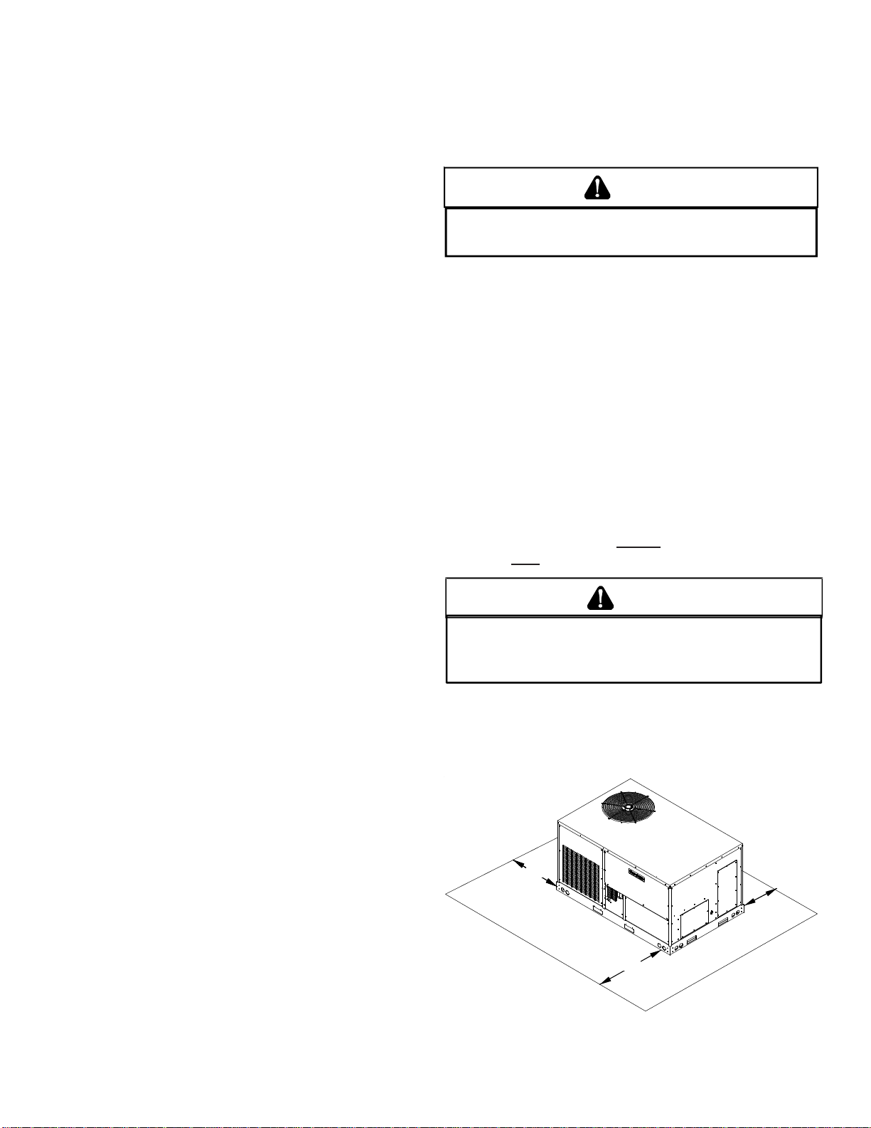
CLEARANCES
ROOF CURB INSTALLATIONS ONLY:
Curb installatons must comply with local codes and should
be done in accordance with the established guidelines of the
National Roofing Contractors Association.
Proper unit installation requires that the roof curb be firmly
and permanently attached to the roof structure. Check for
adequate fastening method prior to setting the unit on the
curb.
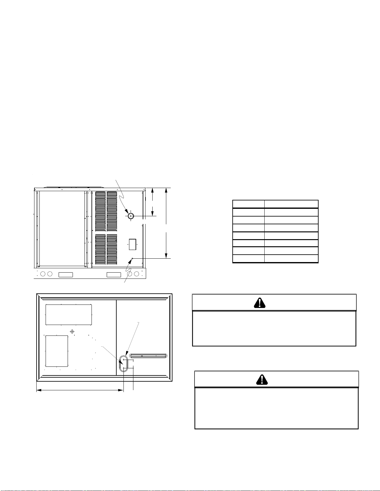
48”
48”
75”
Unit Clearances
5
Page 6
Adequate clearance around the unit should be kept for safety ,
service, maintenance, and proper unit operation. A total clearance of 75” on the main control panel side of the unit is recommended to facilitate possible fan shaft, coil, electric heat
and gas furnace removal. A clearance of 48” is recommended
on all other sides of the unit to facilitate possible compressor
removal, to allow service access and to insure proper ventilation and condenser airflow. The unit must not be installed
beneath any obstruction. The unit should be installed remote from all building exhausts to inhibit ingestion of exhaust
air into the unit fresh air intake.
CAUTION
IF
PROTRUSIONS EXIST, DO NO ATTEMPT TO SET UNIT ON CURB
.
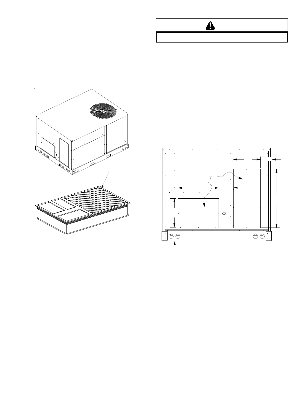
ROOF TOP DUCT CONNECTIONS
Install all duct connections on the unit before placing the unit
on rooftop.
HORIZONTAL DISCHARGE
For horizontal discharge, remove the supply and return duct
covers and place them over the vertical discharge return and
supply openings. Install with insulation facing up, using the
longer screws provided in the literature package.
Ensure that the top of the duct connection frame is flush with
the top of the roof curb.
Flexible duct connectors between the unit and ducts are recommended. Insulate and weatherproof all external ductwork
and joints as required and in accordance with local codes.
11” 4 7/8””
INSULATED
PANELS
Roof Curb Installation
ROOF CURB POST-INST ALLA TION CHECKS
After installation, check the top of the curb, duct connection
frame and duct flanges to make sure gasket has been applied properly. Gasket should be firmly applied to the top of
the curb perimeter, duct flanges and any exposed duct connection frame. If gasket is loose, re-apply using strong
weather resistant adhesive.
PROTRUSION
Inspect curb to ensure that none of the utility services (electric) routed through the curb protrude above the curb.
REMOVE
COVERS
17” 7 3/8”
12”
SUPPL Y
6 3/16”
Horizontal Discharge Duct Connections
25”
6
Page 7
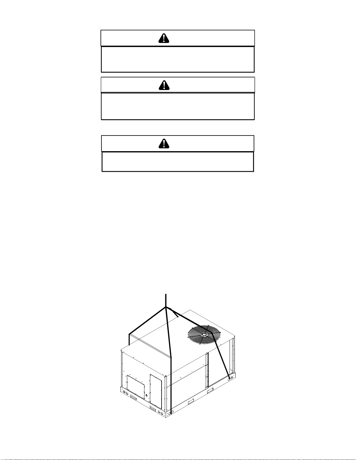
RIGGING DET AILS
WARNING
O PREVENT PROPERTY DAMAGE, THE UNIT SHOULD REMAIN IN AN UPRIGHT
T
T
POSITION DURING ALL RIGGING AND MOVING OPERATIONS.
LIFTING AND MOVING WHEN A CRANE IS USED, PLACE THE UNIT IN AN
ADEQUATE CABLE SLING.
O FACILITATE
CAUTION
IF
UNITS ARE LIFTED TWO AT A TIME, THE FORK HOLES ON THE
CONDENSER END OF THE UNIT MUST NOT BE USED
LENGTH IS
IS RECOMMENDED
42” TO
PREVENT DAMAGE TO THE UNIT; HOWEVER
.
. M
INIMUM FORK
, 48”
Provisions for forks have been included in the unit base frame. No other fork locations are approved.
WARNING
O PREVENT POSSIBLE EQUIPMENT DAMAGE, PROPERTY DAMAGE, PERSONAL
T
INJURY OR DEATH, THE FOLLOWING BULLET POINTS MUST BE OBSERVED
WHEN INSTALLING THE UNIT.
• Unit must be lifted by the four lifting holes located at the base frame corners.
• Lifting cables should be attached to the unit with shackles.
• The distance between the crane hook and the top of the unit must not be less than 60”.
• Two spreader bars must span over the unit to prevent damage to the cabinet by the lift cables. S preader bars must
be of sufficient length so that cables do not come in contact with the unit during transport. Remove wood struts
mounted beneath unit base frame before setting unit on roof curb. These struts are intended to protect unit base
frame from fork lift damage. Removal is accomplished by extracting the sheet metal retainers and pulling the struts
through the base of the unit. Refer to rigging label on the unit.
Important: If using bottom discharge with roof curb, ductwork should be attached to the curb prior to installing the unit.
Ductwork dimensions are shown in Roof Curb Installation Instructions.
Refer to the Roof Curb Installation Instructions for proper curb installation. Curbing must be installed in compliance with the
National Roofing Contractors Association Manual.
Lower unit carefully onto roof mounting curb. While rigging unit, center of gravity will cause condenser end to be lower than
supply air end.
To assist in determining rigging requirements, unit weights are shown as follows:
7
Page 8
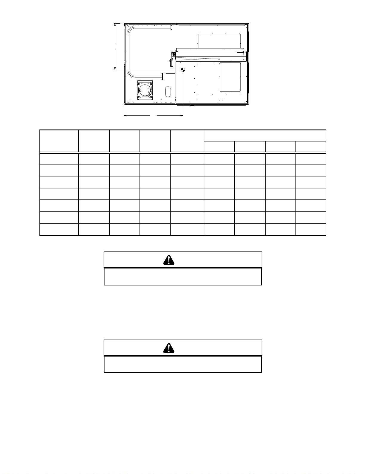
A
C
Y
B
CONDENSER
COIL
COMPRESSOR
X
CG
RETURN
EVAPOR ATOR COIL
SUPPL Y
D
Corner & Center of Gravity Locations
Operating
Weight
(lbs)
Corner Weights ( lbs )
ABCD
Model
X
(in)
Y
(in)
Shipping
Weight
(lbs)
CPG036045* 37 30 550 525 100 165 100 165
CPG036090* 37 30 560 535 100 170 100 170
CPG048090* 37 30 600 575 110 180 110 180
CPG048115* 37 30 605 580 110 180 110 180
CPG060090* 37 30 645 620 115 190 120 195
CPG060140* 37 30 655 630 120 195 120 195
CPG072140* 37 30 715 690 130 215 130 215
* Weights shown are belt drive with no accessories.
CAUTION
TO
PREVENT SEVERE DAMAGE TO THE BOTTOM OF THE UNIT, DO NOT
FORK LIFT UNIT AFTER WOOD STRUTS HAVE BEEN REMOVED
.
Bring condenser end of unit into alignment with the curb. With condenser end of the unit resting on curb member and using
curb as a fulcrum, lower opposite end of the unit until entire unit is seated on the curb. When a rectangular cantilever curb
is used, care should be taken to center the unit. Check for proper alignment and orientation of supply and return openings
with duct.
RIGGING REMOVAL
CAUTION
TO
PREVENT DAMAGE TO THE UNIT, DO NOT ALLOW CRANE HOOKS
AND SPREADER BARS TO REST ON THE ROOF OF THE UNIT
Remove spreader bars, lifting cables and other rigging equipment.
.
8
Page 9
ELECTRICAL WIRING
WARN ING
HIGH VOLTAGE!
ISCONNECT ALL POWER BEFORE SERVICI NG OR
D
INSTALLING THIS UNIT
BE PRESENT
DAMAGE, PERSONAL INJURY OR DEATH
. F
. M
AILURE TO DO SO MAY CAUSE PROPERTY
ULTIPLE POWER SOURCES MAY
.
Electrical Code. If long wires are required, it may be necessary to increase the wire size to prevent excessive voltage
drop. Wires should be sized for a maximum of 3% voltage
drop.
O AVOID PROPERTY DAMAGE OR PERSONAL INJURY DUE TO FIRE, USE
T
ONLY COPPER CONDUCTORS.
CAUTION
WARN ING
HIGH VOLTAGE!
O AVOID PERSONAL INJURY OR DEATH DUE TO
T
ELECTRICAL SHOCK, DO NOT TAMPER WITH FACTORY
WIRING
. THE
OF THESE UNITS ARE FACTORY-INSTALLED AND HAVE
BEEN THOROUGHLY TESTED PRIOR TO SHIPMENT
ONTACT YOUR LOCAL REPRESENTATIVE IF
C
ASSISTANCE IS REQUIRED
INTERNAL POWER AND CONTROL WIRING
.
.
CAUTION
TO
PREVENT DAMAGE TO THE WIRING, PROTECT WIRING FROM
SHARP EDGES
LOCAL CODES AND ORDINANCES
REMOVABLE ACCESS PANELS
. F
OLLOW NATIONAL ELECTRICAL CODE AND ALL
. DO
NOT ROUTE WIRES THROUGH
.
CAUTION
C
ONDUIT AND FITTINGS MUST BE WEATHER-TIGHT TO PREVENT
WATER ENTRY INTO THE BUILDING
.
For unit protection, use a fuse or HACR circuit breaker that is
in excess of the circuit ampacity , but less than or equal to the
maximum overcurrent protection device. DO NOT EXCEED
THE MAXIMUM OVERCURRENT DEVICE SIZE SHOWN
ON UNIT DATA PLATE.
All line voltage connections must be made through weatherproof fittings. All exterior power supply and ground wiring
must be in approved weatherproof conduit.
CAUTION
O PREVENT IMPROPER AND DANGEROUS OPERATION DUE TO WIRING ERRORS,
T
LABEL ALL WIRES PRIOR TO DISCONNECTION WHEN SERVICING CONTROLS.
ERIFY PROPER OPERATION AFTER SERVICING.
V
NOTE: A weather-tight disconnect switch, properly sized for
the unit total load, must be field installed. An external field
supplied disconnect may be mounted on the exterior panel.
Ensure the data plate is not covered by the field-supplied
disconnect switch.
• Some disconnect switches are not fused. Protect the
power leads at the point of distribution in accordance
with the unit data plate.
• The unit must be electrically grounded in accordance
with local codes or, in the absence of local codes,
with the latest edition of the National Electrical Code
(ANSI-NFPA 70). A ground lug is provided for this
purpose. Size grounding conductor in accordance
with T able 250-95 of the National Electrical Code. Do
not use the ground lug for connecting a neutral
conductor.
• Connect power wiring to the compressor contactor
closest to the entrance located within the main control
box.
MAIN POWER
LOW VOLTAGE
BLOCK
The main power supply wiring to the unit and low voltage
wiring to accessory controls must be done in accordance with
these instructions, the latest edition of the National Electriacl
Code (ANSI/NFPA 70), and all local codes and ordinances.
All field wiring shall conform with the temperature limitations
for Type T wire (63°F/35°C rise).
The main power supply for the CPG036XXX3,4,7 through
CPG072 shall be three-phase, three wire. The power supply for the CPG036XXX1 through CPG060 shall be singlephase, two wire. The unit is factory wired for the voltage shown
on the unit’s data plate.
NOTE: If supply voltage is 208V, lead on primary of transformer TRANS1 must be moved from the 230V to the 208V
tap.
Main power wiring should be sized for the minimum wire
ampacity shown on the unit’s database. Size wires in accordance with the ampacity tables in Article 310 of the National
LOW VOLTAGE
ENTRANCE
POWER THRU
THE CURB
Power and Low Voltage Block Connections
WARN ING
F
AILURE OF UNIT DUE TO OPERATION ON IMPROPER LINE VOLTAGE
OR WITH EXCESSIVE PHASE UNBALANCE CONSTITUTES PRODUCT
ABUSE AND WILL VOID YOUR WARRANTY AND MAY CAUSE SEVERE
DAMAGE TO THE UNIT ELECTRICAL COMPONENTS
9
.
Page 10
Areas Without Convenience Outlet
(Hig
)
It is recommended that an independant 115V power source
be brought to the vicinity of the roof top unit for portable lights
and tools used by the service mechanic.
UNITS INSTALLED ON ROOF TOPS
Main power and low voltage wiring may enter the unit through
the condenser end of unit or through the roof curb. Install
conduit connectors at the desired entrance locations. External connectors must be weatherproof. All holes in the unit
base must be sealed (including those around conduit nuts)
to prevent water leakage into building. All required conduit
and fittings are to be field supplied.
Supply voltage to roof top unit must not vary by more than
10% of the value indicated on the unit data plate. Phase
voltage unbalance must not exceed 2%. Contact your local
power company for correction of improper voltage or phase
unbalance.
HIGH VOLTAGE ENTRANCE
(REMOVE PLUG)
2. Locate thermostat or remote sensor in the conditioned
space where it will sense average temperature. Do
not locate the device where it may be directly exposed
to supply air, sunlight or other sources of heat. Follow
installation instructions packaged with the thermostat.
3. Use #18 AWG wire for 24V control wiring runs not
exceeding 75 feet. Use #16 A WG wire for 24V control
wiring runs not exceeding 125 feet. Use #14 AWG
wire for 24V control wiring runs not exceeding 200
feet. Low voltage wiring may be National Electrical
Code (NEC) Class 2 where permitted by local codes.
4. Route thermostat wires from sub-base terminals to
the unit. Control wiring should enter through the
condenser end of unit or through curb. Connect
thermostat and any accessory wiring to low voltage
terminal block TB1 in the main control box.
NOTE: Field-supplied conduit may need to be installed
depending on unit/curb configuration. Use #18 AWG solid
conductor wire whenever connecting thermostat wires to
terminals on sub-base. DO NOT use larger than #18 AWG
wire. A transition to #18 AWG wire may be required before
entering thermostat sub-base.
12 3/8”
30 1/4”*
47 1/2”
1:4
LOW VOLTAGE ENTRANCE
3.5 DIA.
4 1/2”
7 1/2”
* (6 Ton - 34 1/4”)
Electrical Entrance and Thru Curb
POWER THRU
THE CURB
Unit is equipped with a Low Voltage Terminal Block and has
Single Point wiring to the contactor.
LOW VOLTAGE CONTROL WIRING
1. A 24V thermostat must be installed for unit operation.
It may be purchased with the unit or field -supplied.
Thermostats may be programmable or
electromechanical as required.
LEAD THERMOSTAT
Re d R (24V)
Green G (Fan)
Yellow Y1 (High Cool)
Purple Y2 (Low Cool)
Blue C om m on ( if req'd)
White W1 (Heat)
Brown W2
CPG 036 Thru 072 (Gas Heat)
h Heat
GAS SUPPL Y PIPING
WARN ING
TO
PREVENT PERSONAL INJURY OR DEATH DUE TO IMPROPER
INSTALLATION, ADJUSTMENT, ALTERATION, SERVICE OR
MAINTENANCE, REFER TO THIS MANUAL
ASSISTANCE OR INFORMATION, CONSULT A QUALIFIED INSTALLER
SERVICE AGENCY OR THE GAS SUPPLIER
. FOR
.
ADDITIONAL
IMPORTANT NOTE: This unit is factory set to operate on
natural gas at the altitudes shown on the rating plate.
WARN ING
TO
AVOID PROPERTY DAMAGE, PERSONAL INJURY OR DEATH WHEN
EITHER USING PROPANE GAS ALONE OR AT HIGHER ALTITUDES
OBTAIN AND INSTALL THE PROPER CONVERSION KIT(S
DO SO CAN RESULT IN UNSATISFACTORY OPERATION AND/OR
EQUIPMENT DAMAGE
NSTALLATIONS ONLY AND ARE NOT APPROVED FOR USE IN CANADA
I
. H
IGH ALTITUDE KITS ARE FOR
). F
U.S.
AILURE TO
The rating plate is stamped with the model number, type of
gas and gas input rating. Make sure the unit is equipped to
operate on the type of gas available. Conversion to propane
10
,
,
.
Page 11
(LP) gas is permitted with the use of the factory authorized
p
)
g
)
conversion kit (see the unit Technical Manual for the appropriate kit). For High Altitude derates, refer to the latest edition
of the National Fuel Gas Code NFPA 54/ANSI Z223.1.
INLET GAS PRESSUR E
NATURAL
PROPANE
IInlet Gas Pressure Must Not Exceed the Maximum Value Shown in Table
Above.
Min. 5.0" W .C. , Max . 10 .0" W.C.
Min. 11.0" W .C. , M ax . 14 .0" W .C.
The minimum supply pressure should not vary from that
shown in the table above because this could prevent the unit
from having dependable ignition. In addition, gas input to the
burners must not exceed the rated input shown on the rating
plate. Overfiring of the unit could result in premature heat
exchanger failure.
PIPING
IMPORT ANT NOTE: T o avoid possible unsatisfactory opera-
tion or equipment damage due to under firing of equipment,
do not undersize the natural/propane gas piping from the
meter/tank to the unit. When sizing a trunk line, include all
appliances on that line that could be operated simultaneously .
The rating plate is stamped with the model number, type of
gas and gas input rating. Make sure the unit is equipped to
operate on the type of gas available. The gas line installation
must comply with local codes, or in the absence of local codes,
with the latest edition of the National Fuel Gas Code NFPA
54/ANSI Z223.1.
4. Install a drip leg to trap dirt and moisture before it can
enter the gas valve. The drip leg must be a minimum
of three inches long.
5. Use two pipe wrenches when making connection to
the gas valve to keep it from turning.
6. Install a manual shut-off valve in a convenient location
(within six feet of unit) between the meter and the
unit.
7. Tighten all joints securely.
8. The unit must be connected to the building piping by
one of the following methods:
• Rigid metallic pipe and fittings
• Semirigid metallic tubing and metallic fittings
(Aluminum alloy tubing must not be used in exterior
locations)
• Listed gas appliance connectors used in accordance
with the terms of their listing that are completely in
the same room as the equipment
• In the prior two methods above the connector or
tubing must be protected from physical and thermal
damage. Aluminum alloy tubing and connectors must
be coated to protect against external corrosion when
in contact with masonry, plaster or insulation or are
subject to repeated wettings by liquids (water - not
rain water, detergents or sewage).
BURNER
DOOR
Natural Gas Connection
Natural Gas Capaci ty of Pipe
in Cubic Feet of Gas Per H our (C FH)
Length of
Pipe in Feet
10 132 278 520 1050 1600
20 92 190 350 730 1100
30 73 152 285 590 980
40 63 130 245 500 760
50 56 115 215 440 670
60 50 105 195 400 610
70 46 96 180 370 560
80 43 90 170 350 530
90 40 84 160 320 490
100 38 79 150 305 460
Pressure = .50 PSIG or less and Pressure Drop of 0.3" W.C. (Based
CFH =
Heatin
Nominal Black Pipe Si ze (i nches)
1/2 3/4
on 0.60 S
BTUH Furnace Input
Va lu e o f Ga s (BTU/Cubic Foot
1
ecific Gravity Gas
1 1/4 1 1/2
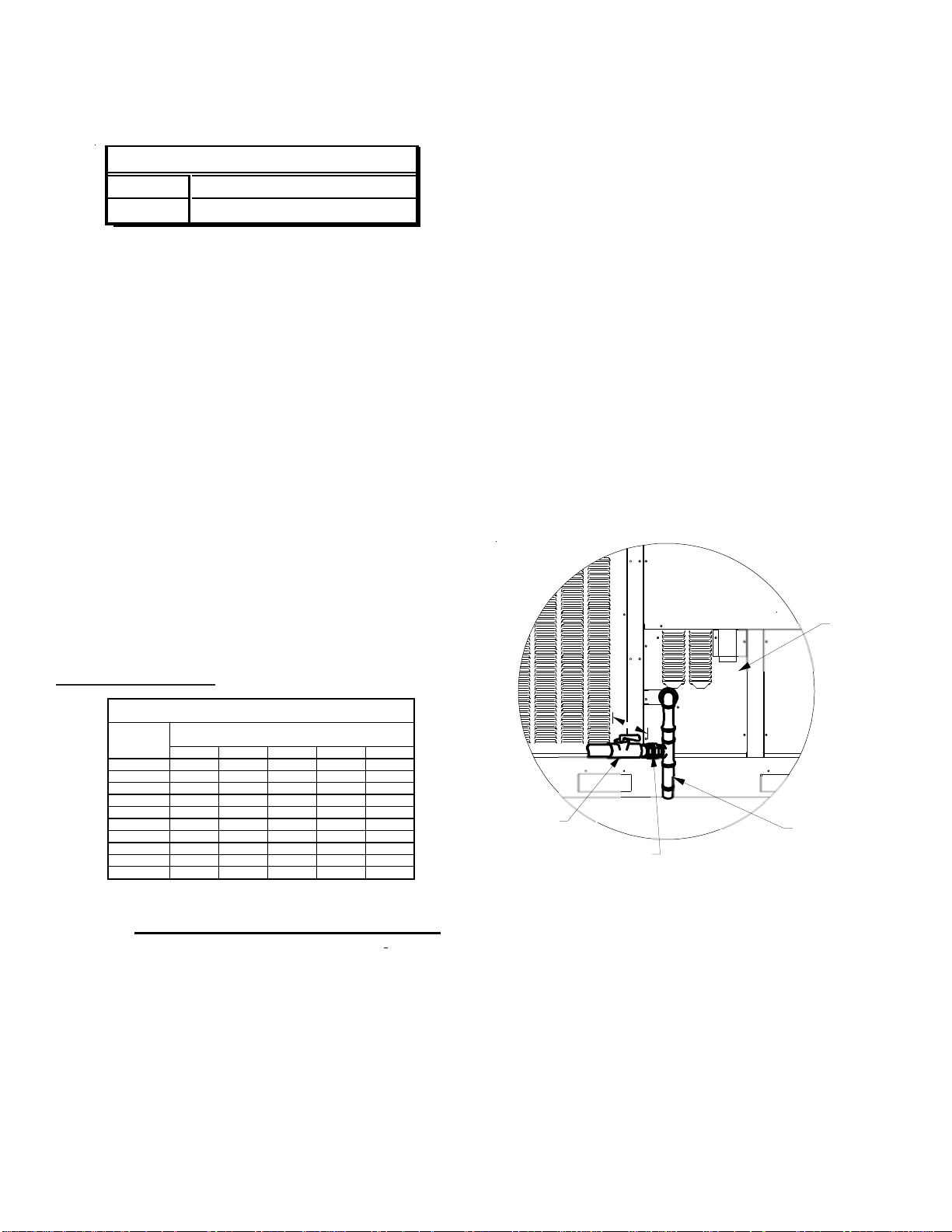
Refer to the Proper Piping Practice drawing for the general
layout at the unit. The following rules apply:
1. Use black iron pipe and fittings for the supply piping.
The use of a flex connector and/or copper piping is
permitted as long as it is in agreement with local
codes.
2. Use pipe joint compound on male threads only. Pipe
joint compound must be resistant to the action of the
fuel used.
3. Use ground joint unions.
TBD
MANUAL
SHUT-OFF
GROUND JOINT
UNION
DRIP
LEG
Proper Piping Practice
NOTE: The unit gas supply entrance is factory sealed with
plugs. Keep plugs in place until gas supply is ready to be
installed. Once ready, replace the plugs with the supplied
grommets and install gas supply line.
11
Page 12
GAS PIPING CHECKS
CAUTION
T
O PREVENT PROPERTY DAMAGE OR PERSONAL INJURY DUE TO FIRE, THE
FOLLOWING INSTRUCTIONS MUST BE PERFORMED REGARDING GAS
CONNECTIONS AND PRESSURE TESTING:
HE UNIT AND ITS GAS CONNECTIONS MUST BE LEAK TESTED BEFORE
•
T
PLACING IN OPERATION.
FIRE, NEVER USE A MATCH OR OPEN FLAME TO TEST FOR LEAKS.
EXCEED SPECI FIED PRES SURES FOR TESTI NG.
DAMAGE GAS VALV E AND CAUSE OVERFIRING WHICH MAY RESULT IN
PREMATURE HEAT EXCHANGE FAILURE.
HIS UNIT AND ITS SHUT-OFF VALVE MUST BE DISCONNECTED FROM
•
T
THE GAS S UPPLY DURING ANY PRESSURE TESTING OF THAT SYSTEM AT
TEST PRESSUR E S IN EX CES S OF 1/2
HIS UNI T MUST BE I SOLAT ED FROM THE GAS SUPPL Y SYS TEM BY
•
T
CLOSING ITS MANUAL SHUT-OFF VALVE DURING ANY PRESSURE
TESTING OF THE GAS SUPPLY PI PING SYSTEM AT TEST PRESSURE S
EQUAL TO OR LESS THAN 1/2
ECAUSE OF THE DANGER OF EXPLOSION OR
B
IGHER PRESSURE MAY
H
(3.48 KPA).
PSIG
(3.48 KPA).
PSIG
WARNING
N
EVER
1. Vaporization rate, which depends on (a) temperature
of the liquid, and (b) wetted surface area of the
container or containers.
2. Proper pressure regulation.
3. Pressure drop in lines between regulators, and
between second stage regulator and the appliance.
Pipe size required will depend on length of pipe run
and total load of all appliances.
TANKS AND PIPING
Complete information regarding tank sizing for
vaporization, recommended regulator settings and pipe
sizing is available from most regulator manufacturers and
propane gas suppliers.
Since propane gas will quickly dissolve white lead or most
standard commercial compounds, special pipe dope
must be used. Shellac base compounds resistant to the
actions of liquefied petroleum gases such as Gasolac®,
Stalactic®, Clyde’s® or John Crane® are satisfactory.
See below for typical propane gas piping.
O AVOID PROPERTY DAMAGE OR PERSONAL INJURY
T
NO OPEN FLAME IN THE VICINITY DURING AIR BLEEDING.
, BE SURE THERE IS
There will be air in the gas supply line after testing for leaks
on a new installation. Therefore, the air must be bled from
the line by loosening the ground joint union until pure gas is
expelled. Tighten union and wait for five minutes until all gas
has been dissipated in the air. Be certain there is no open
flame in the vicinity during air bleeding procedure. The unit is
placed in operation by closing the main electrical disconnect
switch for the unit.
PROP ANE GAS INST ALLA TIONS
WARNING
O AVOID PROPERTY DAMAGE, PERSONAL INJURY O R DEATH DUE TO FIR E
T
OR EXPLOSION CAUSED BY A PROPANE GAS LEAK, INSTALL A G AS
DETECTING WARNING DE VICE.
OF ODORANT IN PROPANE GAS, A GAS DETECTING W ARNING DEVICE
IS THE ONLY RELIABLE WAY TO DETECT A PROPANE GAS LEAK.
ONTACT A LOCAL PROPANE GAS SUPPLIER ABOUT INSTALLING A
C
GAS DETECTING WARNING DEVICE.
INCE RUST CAN REDUCE THE LEVEL
S
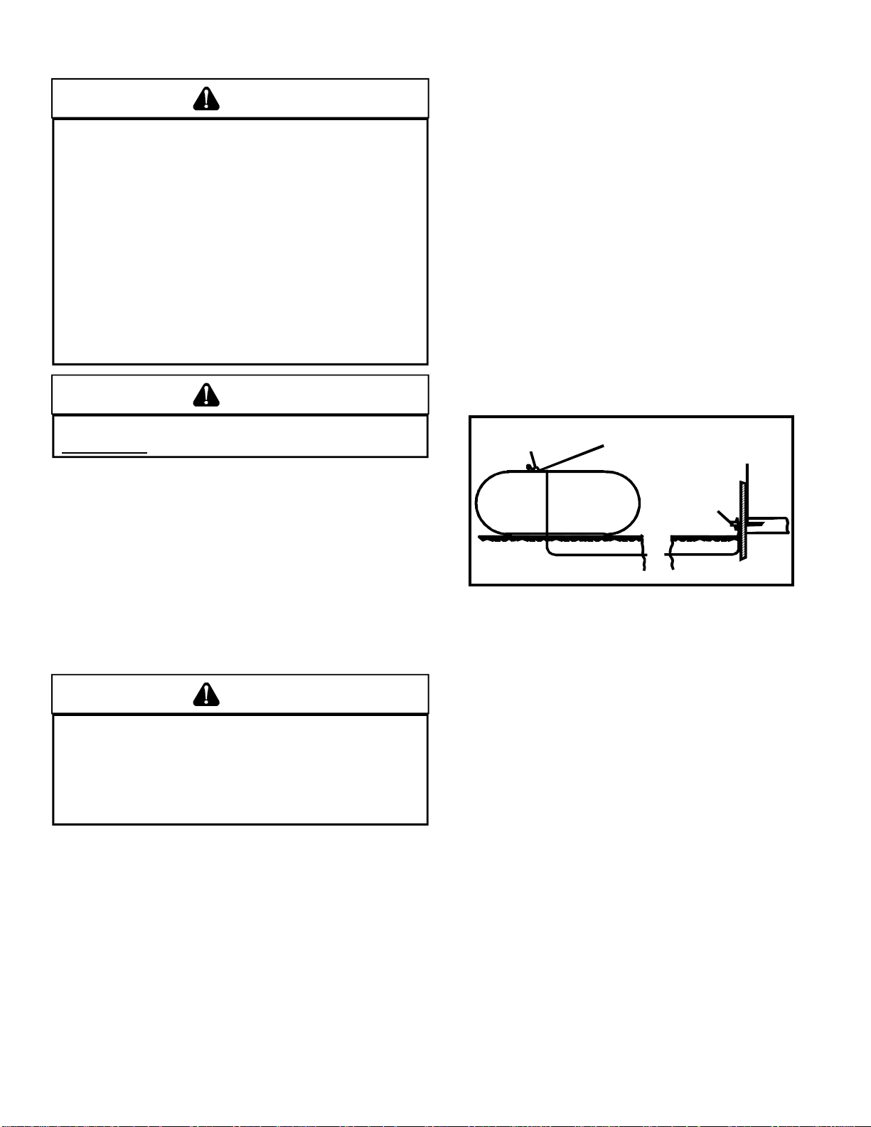
First Stage
Regulator
200 PSIG
Maximum
5 to 15 PSIG
(20 PSIG Max.)
Continuous
Second Stage
Regulator
11" W.C.
Typical Propane Gas Piping
ROOF TOP LOCATION AND INSTALLATION
The gas supply piping location and installation for roof top
units must be in accordance with local codes or, in the absence of locals codes, with ordinances of the latest edition of
the National Fuel Gas Code (ANSI Z223.1).
A manual gas shutoff valve must be field inst alled external to
the roof top unit. In addition, a drip leg must be installed near
the inlet connection. A ground joint union connection is required between the external shutoff valve and the unit connection to the gas valve to permit removal of the burner assembly for servicing.
IMPORTANT NOTE: Propane gas conversion kits must be
installed to convert units to propane gas. NOx screens must
be removed before converting to LP. Remove burner
assembly and pull NOx screens from each burner tube. When
all the screens are out, reassemble the burner assembly
without the screens.
All propane gas equipment must conform to the safety
standards of the National Board of Fire Underwriters (See
NBFU Manual 58).
For satisfactory operation, propane gas supply pressure must
be within 9.7 - 10.3 inches W.C. at the manifold with all gas
appliances in operation. Maintaining proper gas pressure
depends on three main factors:
1. Route gas piping to unit so that it does not interfere
with the removal of access panels. Support and align
piping to prevent strains or misalignment of the
manifold assembly.
2. All units are furnished with standard female NPT pipe
connections. Connection pipe sizes for CPG036
through 072 units is 1/2" NPT on 045 to 140 mBH
units. The size of the gas supply piping to the unit
must be based on length of run, number of units on
the system, gas characteristics, BTU requirement and
available supply pressure. All piping must be done in
accordance with local codes or, in the absence of local
codes, with the latest edition of the National Fuel Gas
Code (ANSI Z223.1).
12
Page 13
NOTE: The gas connection size at the unit does NOT
establish the size of the supply line.
3. These units are designed for either natural or propane
(LP) gas and are specifically constructed at the factory
for only one of these fuels. The fuels are NOT
interchangeable. However, the furnace can be
converted in the field from natural gas to LP gas with
the appropriate factory kit (see unit Technical Manual
for the appropriate kit). Only a qualified contractor,
experienced with natural and propane gas systems,
should attempt conversion. Kit instructions must be
followed closely to assure safe and reliable unit
operation.
4. With all units on a common line operating under full
fire, natural gas main supply pressure should be
adjusted to approximately 7.0" w.c., measured at the
unit gas valve. If the gas pressure at the unit is greater
than 10.5" w.c., the contractor must furnish and inst all
an external type positive shutoff service pressure
regulator. The unit will not function satisfactorily if
supply gas pressure is less than 5.5" w.c. or greater
than 10.5" w.c..
NOTE: A minimum horizontal distance of 48"
between the regulator and the furnace flue discharge
is required.
5. With all units on a common line operating under full
LP gas main supply pressure should be at least 1 1.0"
w.c. and must be no greater than 13.0" w .c., measured
at the unit gas valve. Unit will not function satisfactorily
if supply gas pressure is less than 1 1.0" w.c. or greater
than 13.0" w.c..
6. All pipe connections should be sealed with a pipe
thread compound, which is resistant to the fuel used
with the furnace. A soapy water solution should be
used to check all joints for leaks. A tap is located on
the entering side of the gas valve for test gauge
connection to measure supply (main) gas pressure.
Another tap is provided on the manifold side of the
gas valve for checking manifold pressure.
WARN ING
T
HIS UNIT AND ITS INDIVIDUAL SHUTOFF VALVE MUST BE
DISCONNECTED
PRESSURE TESTING OF THAT SYSTEM AT TEST PRESSURES IN
EXCESS OF
1/2 PSIG (13.8” W.C.).
FROM THE GAS SUPPLY SYSTEM DURING ANY
CIRCULA TING AIR AND FILTERS
DUCTWORK
The supply duct should be provided with an access panel
large enough to inspect the air chamber downstream of the
heat exchanger. A cover should be tightly attached to prevent air leaks.
Ductwork dimensions are shown in the roof curb installation
manual.
If desired, supply and return duct connections to the unit may
be made with flexible connections to reduce possible unit
operating sound transmission.
VENTING
NOTE: Venting is self-contained.
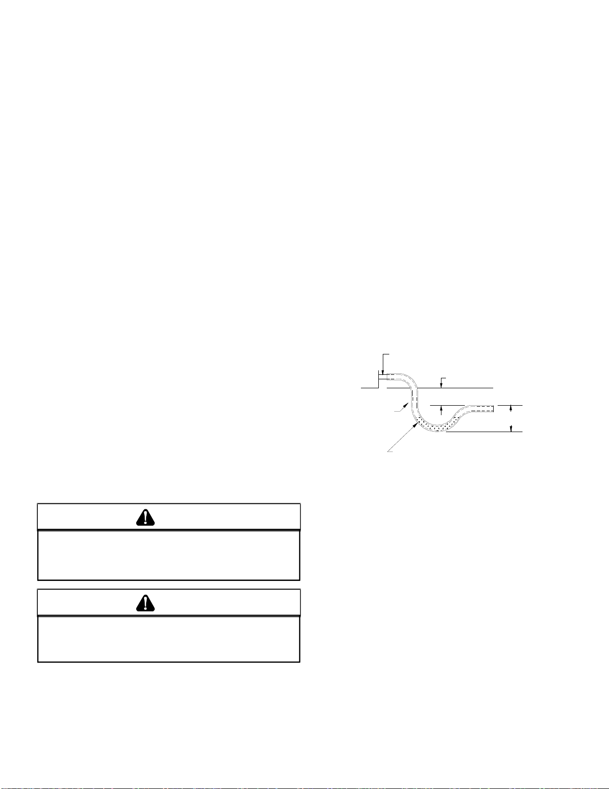
CONDENSA TE DRAIN CONNECTION
CONDENSATE DRAIN CONNECTION
A 3/4” NPT drain connection is supplied for condensate piping. An external trap must be inst alled for proper condensate
drainage.
DRAIN
CONNECTION
UNIT 2" MINIMUM
FLEXIBLE
TUBING-HOSE
OR PIPE
A POSITIVE LIQUID
SEAL IS REQUIRED
Drain Connection
3" MIN IMUM
Install condensate drain trap as shown. Use 3/4" drain line
and fittings or larger. Do not operate without trap.
HORIZONTAL DRAIN
Drainage of condensate directly onto the roof may be acceptable; refer to local code. It is recommended that a small
drip pad of either stone, mortar , wood or metal be provided to
prevent any possible damage to the roof.
CAUTION
T
HIS UNIT MUST BE
SYSTEM BY CLOSING ITS INDIVIDUAL MANUAL SHUTOFF VALVE
DURING ANY PRESSURE TESTING EQUAL TO OR LESS THAN
PSIG.
ISOLAT ED
FROM THE GAS SUPPLY PIPING
1/2
7. There must be no obstruction to prevent the flow of
combustion and ventilating air. A vent stack is not
required and must never be used. The power venter
will supply an adequate amount of combustion air as
long as the air passageways are kept free of any
obstructions and the recommended external unit
clearances are maintained.
CLEANING
Due to the fact that drain pans in any air conditioning unit
will have some moisture in them, algae and fungus will
grow due to airborne bacteria and spores. Periodic cleaning is necessary to prevent this build-up from plugging the
drain.
13
Page 14
ST ARTUP , ADJUSTMENTS, AND CHECKS
WARN ING
HIGH VOLTAGE!
O AVOID PERSONAL INJURY OR DEATH DUE TO
T
ELECTRICAL SHOCK, B
THE BUILDING ELECTRICAL GROUND BY USE OF THE
GROUNDING TERMINAL PROVIDED OR OTHER
ACCEPTABLE MEANS
SERVICING OR INSTALLING THIS UNIT
OND THE FRAME OF THIS UNIT TO
. D
ISCONNECT ALL POWER BEFORE
.
TOOLS REQUIRED
Refrigeration gauge and manifold
Voltmeter
Clamp-on ammeter
Ohmmeter
Test lead
(Minimum #16 AWG with insulated alligator clips)
Manometer for verifying gas pressure 0 to 20" w.c.
Air temperature measuring device
General refrigeration mechanics’ tools
PRE-STARTUP INSTRUCTIONS
CAUTION
TO
PREVENT PROPERTY DAMAGE OR PERSONAL INJURY
START THE UNIT UNTIL ALL NECESSARY PRE-CHECKS AND TESTS
HAVE BEEN PERFORMED
.
, DO
NOT
Prior to the beginning of Startup, Adjustments, and Checks
procedures, the following steps should be completed in the
building.
THERMOSTAT. Set the thermostat in the conditioned
space at a point at least 10°F below zone temperature.
Set the thermostat system switch on COOL and the
fan switch on AUTO.
WARN ING
MOVING MACHINERY HAZARD!
O PREVENT POSSIBLE PERSONAL INJURY OR DEATH, DISCONNECT
T
POWER TO THE UNIT AND PADLOCK IN THE
SERVICNG FANS
.
“OFF”
POSITION BEFORE
HEATING STARTUP
This unit is equipped with an electronic ignition device to automatically light the main burners. It also has a power vent
blower to exhaust combustion products.
On new installations, or if a major component has been replaced, the operation of the unit must be checked.
TEMPORARY HEATING OR COOLING
If the unit is to be used for temporary heating or cooling, a
“Startup, Adjustments, and Checks” must first be performed
in accordance with this manual. Failure to comply with this
requirement will void the warranty. After the machines are
used for temporary heating or cooling, inspect the coils, fans,
and motors for unacceptable levels of construction dust and
dirt and install new filters.
CONTRACTOR RESPONSIBILITY
The installing contractor must be certain that:
• All supply and return air ductwork is in place and
corresponds with installation instructions.
• All thermostats are mounted and wired in accordance
with installation instructions.
• All electric power, all gas, hot water or steam line
connections, and the condensate drain installation
have been made to each unit on the job. These main
supply lines must be functional and capable of
operating all units simultaneously.
ROOF CURB INSTALLATION CHECK
Inspect the roof curb for correct installation. The unit and curb
assembly should be level. Inspect the flashing of the roof
mounting curb to the roof, especially at the corners, for good
workmanship. Also check for leaks around gaskets. Note any
deficiencies in a separate report and forward to the contractor.
Check unit operation as outlined in the following instructions.
If any sparking, odors, or unusual sounds are encountered,
shut off electrical power and recheck for wiring errors, or obstructions in or near the blower motors. Duct covers must
be removed before operating unit.
The Startup, Adjustments, and Checks procedure provides a
step-by-step sequence which, if followed, will assure the
proper startup of the equipment in the minimum amount of
time. Air balancing of duct system is not considered part of
this procedure. However, it is an important phase of any air
conditioning system startup and should be performed upon
completion of the Startup, Adjustments, and Checks procedure. The Startup, Adjustments, and Checks procedure at
outside ambients below 55°F should be limited to a readiness check of the refrigeration system with the required final
check and calibration left to be completed when the outside
ambient rises above 55°F.
OBSTRUCTIONS, FAN CLEARANCE AND WIRING
Remove any extraneous construction and shipping materials that may be found during this procedure. Rotate all fans
manually to check for proper clearances and that they rotate
freely . Check for bolts and screws that may have jarred loose
during shipment to the jobsite. Retighten if necessary. Retighten all electrical connections.
PRE-STARTUP PRECAUTIONS
It is important to your safety that the unit has been properly
grounded during installation. Check ground lug connection
in main control box for tightness prior to closing circuit breaker
or disconnect switch. Verify that supply voltage on line side
of disconnect agrees with voltage on unit identification plate
and is within the utilization voltage range as indicated in
Appendix C Electrical Data.
14
Page 15
System Voltage - That nominal voltage value assigned to a
circuit or system for the purpose of designating its voltage
class.
Nameplate Voltage - That voltage assigned to a piece of
equipment for the purpose of designating its voltage class
and for the purpose of defining the minimum and maximum
voltage at which the equipment will operate.
Utilization Voltage - The voltage of the line terminals of the
equipment at which the equipment must give fully satisfactory performance. Once it is established that supply voltage
will be maintained within the utilization range under all system conditions, check and calculate if an unbalanced condition exists between phases. Calculate percent voltage unbalance as follows.
Three Phase Models Only
2) MAXIMUM VOLTAGE DEVIATIONS
3) PERCENT VOLTAGE
UNBALANCE
HOW TO USE THE FORMULA:
EXAMPLE: With voltage of 220, 216, and 213
1) Average Voltage = 220+216+213=649 / 3 = 216
2) Maximum Voltage Deviation s fro m Average Voltage = 220 - 216 = 4
3) Percent Voltage Unbalance = 100 x = = 1.8%
Percent voltage unbalance MUST NOT exceed 2%
= 100 X
FROM AVERAGE VOLT AG E
1) AVERAGE VOLTAGE
4
216
400
216
.
SET EVAPORATOR FAN RPM
Actual RPM’s must be set and verified with a tachometer or
strobe light. Refer to Appendices A and B for basic unit fan
RPM. Refer also to “Airflow” section of this manual. With
disconnect switch open, disconnect thermostat wires from
terminals Y and W . This will prevent heating and mechanical
cooling from coming on. Place a jumper wire across terminals R and G at TB1 terminal block. Close disconnect switch;
evaporator fan motor will operate so RPM can be checked.
For gas heat units, the airflow must be adjusted so that the
air temperature rise falls within the ranges given stated on
Data Plate (see Appendix A - Blower Performance).
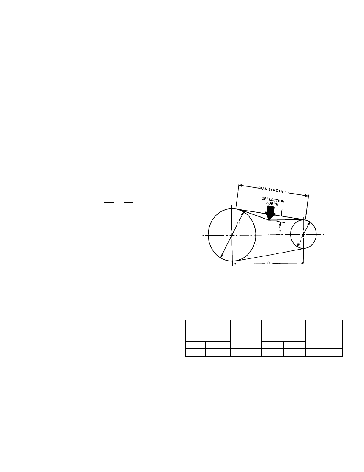
TENSION AND ALIGNMENT ADJUSTMENT
Correct belt tension is very important to the life of your belt.
Too loose a belt will shorten its life; too tight, premature motor and bearing failure will occur. Check you belt drive for
adequate “run-in” belt tension by measuring the force required
to deflect the belt at the midpoint of the span length. Belt
tension force can be measured using a belt tension gauge,
available through most belt drive manufacturers.
FIELD DUCT CONNECTIONS
Verify that all duct connections are tight and that there is no
air bypass between supply and return.
CONTROL VOLTAGE CHECK
With disconnect switch in the open “OFF” position, disconnect blue wire from low voltage transformer TRANS1. Close
the disconnect switch to energize TRANS1 control transformer. Check primary and secondary (24V) of control transformer TRANS1.
THERMOSTAT PRELIMINARY CHECK
With disconnect switch open and blue wire disconnected from
TRANS1 transformer, att ach one lead of ohmmeter to terminal R on TB1 terminal block. Touch, in order, the other ohmmeter lead to terminals Y1, Y2 and G at TB1 terminal block.
There must be continuity from terminal R to terminals Y and
G. R to Y indicates cool. R to G indicates fan (auto). Replace
blue wire on TRANS1 transformer.
FILTER SECTION CHECK
Remove filter section access panels and check that filters
are properly installed. Note airflow arrows on filter frames.
BELT DRIVE MODELS ONLY
BEARING CHECK
Prior to energizing any fans, check and make sure that all
setscrews are tight so that bearings are properly secured to
shafts.
Belt Tension Adjustment
t = Span length, inches
C = Center distance, inches
D = Larger sheave diameter, inches
d = Smaller sheave diameter, inches
h = Deflection height, inches
SMALL
TYPE DEFLECTION
BELT DRIVE USED NEW
AX Standard 3.0 to 4.0 4.2 ± 0.5 5.5 ± 0.5 0.313
Recommended Pounds of Force Per Belt
SHEAVE
DIAMETER
(in)
DEFLECTION
FORCE (lbs)
(in)
New V-belts will drop rapidly during the first few hours of use.
Check tension frequently during the first 24 hours of operation. T ension should fall between the minimum and maximum
force. To determine the deflection distance from a normal
position, measure the distance from sheave to sheave using
a straightedge or a cord. This is your reference line. On multiple belt drives, an adjacent undeflected belt can be used as
a reference.
15
Page 16
EVAPORATOR FAN ROTATION CHECK (THREE PHASE MODELS
ONLY)
Check that fan rotates clockwise when viewed from the drive
side of unit and in accordance with rotation arrow shown on
blower housing. If it does not, reverse any two incoming power
cables at Single Point Power Block. In this case, repeat bearing check.
Do not attempt to change load side wiring. Internal wiring
assures all motors and compressors will rotate in correct direction once evaporator fan motor rotation check has been
made.
ELECTRICAL INPUT CHECK
Make preliminary check of evaporator fan ampere draw and
verify that motor nameplate amps are not exceeded. A final
check of amp draw should be made upon completion of air
balancing of the duct system (see Appendix C).
RESTORING CONNECTIONS
With disconnect switch open, remove jumper wire from terminals R and G at TB1 terminal block, and reconnect thermostat wires to terminals Y and W.
REFRIGERATION SYSTEM CHECKS
Ensure the hold-down bolts on the compressor are secure
and have not vibrated loose during shipment. Check that vibration grommets have been installed. Visually check all piping and clamps. The entire refrigeration system has been
factory charged and tested, making it unnecessary to field
charge. Factory charges are shown in Appendix C and on
the unit nameplate.
Install service manifold hoses. Gauges should read saturation pressure corresponding to ambient temperature. Charge
should be checked to obtain 12° to 15° of sub-cooling per
system (i.e. compressor circuits).
If the power to the unit is interrupted during the heating cycle,
it may cause the secondary limit to trip. Once the blower compartment temperature drops below the limit reset temperature, the limit will automatically reset. The unit will restart
after one (1) hour.
Pre-Operation Checks
1. Close the manual gas valve external to the unit.
2. Turn off the electrical power supply to the unit.
3. Set the room thermostat to its lowest possible setting.
4. Remove the heat exchanger door on the side of the
unit by removing screws.
5. This unit is equipped with an ignition device which
automatically lights the main burner. DO NOT try to
light burner by any other method.
6. Move the gas control valve switch to the OFF position.
Do not force.
7. Wait five minutes to clear out any gas.
8. Smell for gas, including near the ground. This is
important because some types of gas are heavier than
air. If you have waited five minutes and you do smell
gas, immediately follow the warnings on page 3 of
this manual. If having waited for five minutes and no
gas smell is noted, move the gas control valve switch
to the ON position.
9. Replace the heat exchanger door on the side of the
unit.
10.Open the manual gas valve external to the unit.
11. Turn on the electrical power supply to the unit.
12.Set the thermostat to desired setting.
Gas Supply And Manifold Check
Gas supply pressure and manifold pressure with the burners
operating must be as specified on the rating plate.
Gas Inlet Pressure Check
Gas inlet pressure must be checked and adjusted in accordance to the type of fuel being consumed.
Rollout Protection Control
The rollout protection device opens, cutting power to the
gas valve, if the flames from the burners are not properly
drawn into the heat exchanger. The rollout protection
device is located on the burner bracket. The reason for
elevated temperatures at the control should be
determined and repaired prior to resetting this manual
reset control.
WARNING
O AVOID PROPERTY DAMAGE, PERSONAL INJURY OR DEATH DUE TO FIRE
T
OR EXPLOSION, A QUALIFIED SERVICER MUST INVESTIGATE THE REASON FOR
THE ROLLOUT PROTECTION DEVICE TO OPEN BEFORE MANUALLY RESETTING
THE ROLLOUT PROTECTION DEVICE.
Secondary Limit Control
The secondary limit control is located on the top of the blower
scroll assembly . This control opens when elevated temperatures are sensed. Elevated temperatures at the control are
normally caused by blower failure. The reason for the opening should be determined and repaired prior to resetting.
With Power And Gas Off:
1. Connect a water manometer or adequate gauge to
the inlet pressure tap of the gas valve.
Inlet gas pressure can also be measured by removing
the cap from the dripleg and installing a predrilled cap
with a hose fitting.
With Power And Gas On:
2. Put unit into heating cycle and turn on all other gas
consuming appliances.
INLET GAS PRESSUR E
NATURAL
PROPANE
Min. 5.0" W .C. , Max . 10 .0" W.C.
Min. 11.0" W .C. , Max . 14.0" W .C.
NOTE: Inlet Gas Pressure Must Not Exceed the Maximum
Value Shown.
If operating pressures differ from above, make necessary
pressure regulator adjustments, check piping size, etc., and/
or consult with local utility.
16
Page 17

Manifold Pressure Check
The gas valve has a tapped opening to facilitate measurement of the manifold pressure. A “U” Tube manometer having a scale range from 0 to 12 inches of water should be
used for this measurement. The manifold pressure must be
measured with the burners operating.
1. With disconnect switch open, remove field connected
thermostat wire from terminal R, W1 and W2 on TB1.
Place jumper wire between R, W1 and W2 to engage
high stage heat. (note on 045 kbtu/hr units W2 is not
used, only jumper R to W1).
2. See Figure in input rating section for gas valve
adjustment.
T o adjust the pressure regulator , remove the adjustment screw
or cover on the gas valve. Turn out (counterclockwise) to
decrease pressure, turn in (clockwise) to increase pressure.
Only small variations in gas flow should be made by means
of the pressure regulator adjustment. In no case should the
final manifold pressure vary more than plus or minus 0.3
inches water column from the specified nominal pressure.
Any major changes in flow should be made by changing the
size of the burner orifices. The measured input rate to the
furnace must not exceed the rating specified on the unit rating plate.
For natural gas, the high stage manifold pressure must be
between 3.2 and 3.8 inches water column (3.5 nominal). Low
stage manifold pressure must be between 1.7 to 2.3 inches
water column (2.0 nominal).
3. To set low fire rate on 090, 1 15 and 140 kbtu/hr: Open
disconnect switch, and remove jumper from R to W2.
T o set low fire manifold pressure, repeat steps above.
Refer to Figure in input rating section for location of
high and low stage adjustment.
For propane gas, the manifold pressure must be between
9.7 and 10.3 inches water column (10.0 nominal). Low stage
manifold must be between 5.7 and 6.3 inches water column
(6.0 nominal).
4. Relight all other appliances turned off in step 1. Be
sure all pilot burners are operating.
Main Burner Flame Check
Flames should be stable, soft and blue (dust may cause orange tips but they must not be yellow) and extending directly
outward from the burner without curling, floating or lifting off.
NOx Screen Check
Verify that the alignment of the NOx screens is at 6 o' clock.
In jurisdictions that do not require low NOx emissions, NOx
screens may be removed.
Temperature Rise Check
Check the temperature rise through the unit by placing thermometers in supply and return air registers as close to the
unit as possible. Thermometers must not be able to sample
temperature directly from the unit heat exchangers, or false
readings could be obtained.
1. All registers must be open; all duct dampers must be
in their final (fully or partially open) position and the
unit operated for 15 minutes before taking readings.
2. The temperature rise must be within the range specified
on the rating plate.
NOTE: Air temperature rise is the temperature difference
between supply and return air.
With a properly designed system, the proper amount of temperature rise will normally be obtained when the unit is operated at rated input with the recommended blower speed.
If the correct amount of temperature rise is not obtained, it
may be necessary to change the blower speed. A higher
blower speed will lower the temperature rise. A slower blower
speed will increase the temperature rise.
NOTE: Blower speed MUST be set to give the correct air
temperature rise through the unit as marked on the rating
plate.
Gas Input (Natural Gas Only) Check
To measure the gas input use a gas meter and proceed
as follows:
1. Turn off gas supply to all other appliances except the
unit.
2. With the unit operating, time the smallest dial on the
meter for one complete revolution. If this is a 2 cubic
foot dial, divide the seconds by 2; if it is a 1 cubic foot
dial, use the seconds as is. This gives the seconds
per cubic foot of gas being delivered to the unit.
3. INPUT=GAS HTG VALUE x 3600 / SEC. PER CUBIC
FOOT
Example: Natural gas with a heating value of 1000 BTU per
cubic foot and 34 seconds per cubic foot as determined by
Step 2, then:
Input = 1000 x 3600 / 34 = 106,000 BTU per Hour.
NOTE: BTU content of the gas should be obtained
from the gas supplier. This measured input must not
be greater than shown on the unit rating plate.
REFRIGERATION SEQUENCE CHECK
With the disconnect switch open, remove the field connected
thermostat wire from terminal R on TB1 terminal block. Place
a jumper across terminals R and G, and across R and Y on
TB1 terminal block. Close the disconnect switch. The following operational sequence should be observed.
1. Current through primary winding of transformer
TRANS1 energizes the 24-volt control circuit.
2. To simulate a mechanical call for cooling from the wall
thermostat, place a jumper across terminals R and Y
of terminal block TB1. The cooling is energized when
the room temperature is above the thermostat setpoint for cooling. The thermostat makes R to Y.
3. UNIT WITH ECONOMIZER OPTION: The
compressor circuit is interlocked through terminals 3
and 4 of the economizer module. If the outdoor air
enthalpy (temperature and humidity) is not suitable
for cooling, the economizer terminals will be closed
permitting compressor to be energized.
17
Page 18

4. The belt drive blower contactor closes its contacts L1,
L2 and L3 to T1, T2 and T3 to provide power to the
supply fan motor.
PSC Motor
Adjust the CFM for the unit by changing the speed
tap of the indoor blower motor at the EBTDR “com”
connection with one of the speed taps on “M1” or “M2”.
(Black-High Speed, Blue-Medium Speed, Red-Low
Speed.)
EEM Motor
Adjust the CFM for the unit by changing the position
of the low voltage leads on the motor terminal block.
White is for fan only and gas heat, Y ellow is for cooling.
Refer to Appendix A for blower performance at each
speed tap. NOTE: If more than one lead is energized
simultaneously , the motor will run at the higher speed.
5. Check supply fan rotation. If the supply fan is rotating
in the wrong direction, disconnect and lock off Single
Point Power Block. Do not attempt to change load
side wiring. Internal wiring is set at the factory to assure
that the supply fan and compressors all rotate in the
proper direction. Verification of correct supply fan
rotation at initial startup will also indicate correct
compressor rotation. Reconnect power and check for
proper operation.
6. Compressor contactor closes its contacts L1, L2 and
L3 to T1, T2 and T3 to provide power to the
compressor motor COMP . 1. In addition, cont actor C1
closes its contact L3 to T3 , energizing the condenser
fan motor.
WARN ING
7. Disconnecting the jumper wire between R and Y and
between R and G on TB1 terminal block will simulate
a satisfied thermostat. The compressor will cycle off
and IIC (pin 12) will initiate its time delay cycle. The
compressor and the supply fan will cycle off.
8. After a time delay of approximately 3 minutes, the
compressor control circuits will be ready to respond
to a subsequent call for cooling from the wall
thermostat.
9. Open disconnect switch. Reconnect the field
thermostat wire at terminal R on terminal block TB1.
REFRIGERATION PERFORMANCE CHECK
Under normal summertime (full load) operating conditions,
superheat should be between 8°F and 12°F and sub-cooling
measured at the condenser outlet should be 15°F (nominal).
A 25°F to 35°F temperature difference should exist between
the entering condenser air and the temperature corresponding to the compressor saturated discharge pressure. Check
that compressor RLA corresponds to values shown in Appendix C. RLA draw can be much lower than values listed at
low load conditions and low ambient condensing temperatures. Values in Appendix C can slightly exceed at high load
conditions and high ambient condensing temperatures.
GAS SUPPLY PRESSURES & REGULATOR ADJUSTMENTS
WARN ING
S
HOULD OVERHEATING OCCUR OR THE GAS SUPPLY FAIL TO SHUT
OFF, TURN OFF THE MANUAL GAS SHUTOFF VALVE EXTERNAL TO THE
UNIT BEFORE TURNING OFF THE ELECTRICAL SUPPLY
.
DO NOT T OUCH! DISCHARGE LINE MAY BE HOT!
BURN HA Z ARD!
7. Check that the compressor is operating correctly. The
scroll compressors in these units MUST operate in
the proper rotation. To ensure the compressors are
operating in the correct direction, check the
compressor discharge line pressure or temperature
after the compressor is started.
The discharge pressure and discharge line
temperature should increase. If this does not occur
and the compressor is producing an exceptional
amount of noise, perform the following checks.
• Ensure all compressors and the supply fan motor
are operating in the proper direction. If a single motor
is operating backwards, check the power wiring for
that motor and correct any leads that have been
interchanged at the contactor or at the motor.
• If all of the motors are operating backward,
disconnect the unit power supply and lock it in the
“OFF” position. Switch two leads of the power supply
at the unit Single Point Power Block. Reconnect
power and check for compressor and supply fan
motor operation.
6. With all safety devices closed, the system will continue
cooling operation until the thermostat is satisfied.
WARN ING
TO
AVOID PROPERTY DAMAGE, PERSONAL INJURY OR DEATH, DO
NOT FIRE GAS UNIT WITH FLUE BOX COVER REMOVED
.
NOTE: Except during brief periods when gas pressures are
being measured by qualified service personnel, the furnace
access panel must always be secured in place when the
furnace is in operation. An inspection port in the access p anel
is provided to monitor the flame.
The first step in checking out the gas-fired furnace is to test
the gas supply piping to the unit for tightness and purge the
system of air using methods outlined in the latest edition of
the National Fuel Gas Code ANSI Z223.1. Verify that the
disconnect switch is in the “OFF” position. A soapy water
solution should be used to check for gas leaks. Since the unit
is subject to considerable jarring during shipment, it is extremely important that all gas connections and joints be tested
for tightness. Gas piping downstream from the unit inlet should
be checked for leaks during the subsequent sequence check.
The supply gas pressure should be adjusted to 7.0" w.c. on
natural gas and 1 1.0" on LP gas with the gas burners operating. If there is more than one unit on a common gas line, the
pressures should be checked with all units under full fire. A
18
Page 19

supply pressure tap is provided on the upstream side of the
gas valve. A manifold pressure tap is provided on the gas
valve. The normal manifold pressure for full input is 3.5" w .c.
on natural gas and 9.5" w.c. for propane gas. Low fire natural gas 2.0” w.c., 6.0” low fire propane gas. Minimum gas
supply pressure is 5.5" w.c. for natural gas and 11.0" for propane gas. In order to obtain rating, gas supply pressure must
be 11.0" w.c. for propane gas.
3. Remove the heat exchanger door on the side of the
unit by removing screws.
4. Move the gas control valve switch to the OFF position.
Do not force.
5. Close manual gas shutoff valve external to the unit.
6. Replace the heat exchanger door on the unit.
7. If cooling and/or air circulation will be desired, turn
ON the electrical power.
The pressure regulator on LP gas models is adjusted for 9.5"
w.c. manifold pressure and is intended to prevent over-firing
only . Do not attempt adjustment of the built-in pressure regulator unless the supply pressure is at least 7.0" w.c. on natural gas or 13.0" w.c. on propane gas. Check the location of
the ignition electrode and the flame sensor for correct gap
setting.
Flame Sensor and Ignition Electrode Location
MAXIMUM
INPUT
(BTUH)
45,000 2 23,000 #43 #55
115,000 5 23,000 #43 #55
140,000 6 23,000 #43 #55
90,000 4 23,000 #43 #55
NUMBER
of
BURNERS
Heat Exchanger and Burner Orifice Specifications
MAXIMUM
BTUH/BURNER
GAS ORIFICES
NATURAL
(Dia)
PROPANE (LP)
(Dia)
NOTE: Gas appliances located more than 2000 feet above
sea level must be derated 4% per 1000 feet of total elevation
and that variance in gas heating value and specific gravity
require change in manifold pressure to obtain rating, it is
mandatory that the input be adjusted at the installation site.
All installations should be made as outlined in the latest edition
of the National Fuel Gas Code ANSI Z223.1,section
“Procedures To Be Followed To Place An Appliance in
Operation”. Refer also to the “User’s Information Manual”
supplied with the unit for additional information on the gas
furnace.
Unit Shutdown
1. Set the thermostat to lowest setting.
2. Turn off the electrical power supply to the unit.
NORMAL SEQUENCE OF OPERA TION
HEATING
This unit has one (RS) Manual Reset Limit Control Switch.
Check the limit to make sure it has not tripped. The limit may
arrive at the job site tripped as a result of shipping shock.
If the ventermotor comes on, but the unit does not attempt
ignition, check if the ALS (Auxiliary High Limit Control Switch)
requires resetting.
1. With electricity and gas turned on, the system switch
in the “HEAT” or “AUTO” position and the fan switch
in the “AUTO” position, the thermostat will close the
circuit between unit terminals R and W (R-W) when
the temperature falls below the thermostat setting.
2. D1 on IIC energizes relay IDMR.
3. Relay IDMR energizes the ventermotor IDM.
4. Operation of the ventermotor closes the pressure
switch PS located in the burner compartment. Unless
excessive temperatures or shipping shock have
opened high limit control ALS, power is fed to the
integrated ignition control, which then initiates a 15second pre-purge time delay. During this period, the
ventermotor will clear the combustion chamber of any
residual gas.
5. After the pre-purge period, the ignition control
energizes the Wl-C gas valve and simultaneously
initiates a “three (3)-try” spark ignition sequence.
6. When the burners are ignited, a minimum one (1)
micro-amp DC current will flow through the flame
between the sensor electrode and the grounded
burner.
7. When the controller proves that the flame has been
established, it will keep the gas valve energized and
discontinue the ignition spark. High stage manifold
pressure will be approximately 3.5" w.c. for natural
gas and 10.0" w.c. for propane (LP). Low fire natural
gas is 2.0” w.c.; low fire propane 6.0” w.c.
8. If the control is unable to ignite the burners after its
initial attempt, it will initiate another purge and spark
sequence. A third purge and spark sequence will be
initiated if the second attempt is unsuccessful. If the
third attempt is unsuccessful, the controller will close
the gas valve and lock itself out. It may be reset by
momentarily interrupting power. This may be
accomplished by briefly lowering the room thermostat
set-point below room temperature, or by shutting off
the main power to the unit. (See TP-105 for more
details.)
19
Page 20

9. Integrated ignition control will close its normally open
contacts after a delay of approximately 30 seconds.
This action energizes contactor BC and starts the
supply fan motor. Operation of the supply fan
circulates air across the heat exchanger and delivers
heated air to the conditioned space.
10. When the space temperature rises, the thermostat
will open R-W. Opening R-W will cause the gas valve
to close, and the furnace to shut down.
1 1. The furnace has three high temperature limit controls,
which can shut down the burner. They do not shut
down the ventermotor.
AUTOMATIC RESET HIGH LIMIT CONTROL (LS)
Located in the burner compartment on the heat exchanger,
its sensing element projects through the blower section bulkhead and senses the temperature at the rear of the furnace.
It will cycle the furnace off if the temperature exceeds 100°F
plus maximum rise.
AUXILIARY HIGH LIMIT CONTROL (ALS)
Located in the blower compartment on the blower housing, it
senses air temperature within the blower compartment and
protects the filters from excessive temperature. It will shut
down the furnace if it senses excessive temperatures.
MANUAL RESET FLAME ROLLOUT CONTROL (RS)
Located in the burner compartment at the top of the burner
assembly, it senses high temperature that could occur if the
heat exchanger tubes were plugged and the flame was rolling out instead of entering the tubes. It has a manual pushbutton reset that cannot be actuated until the limit control has
cooled.
TROUBLESHOOTING
IGNITION CONTROL ERROR CODES
The following presents probable causes of questionable unit
operation. Refer to Diagnostic Indicator Chart for an interpretation of the signal and to this section for an explanation.
Remove the control box access panel and note the number
of diagnostic LED flashes. Refer to Diagnostic Indicator Chart
for an interpretation of the signal and to this section for an
explanation.
ABNORMAL OPERATION - HEATING
Internal Control Failure
If the integrated ignition control in this unit encounters an internal fault, it will go into a “hard” lockout and turn off the
diagnostic LED. If diagnostic LED indicates an internal fault,
check power supply to unit for proper voltage, check all fuses,
circuit breakers and wiring. Disconnect electric power for
five seconds. If LED remains off after restoring power, replace control.
External Lockout
An external lockout occurs if the integrated ignition control
determines that a measurable combustion cannot be established within three (3) consecutive ignition attempts. If flame
is not established within the seven (7) second trial for ignition, the gas valve is deenergized, 15 second inter-purge cycle
is completed, and ignition is reattempted. The control will
repeat this routine three times if a measurable combustion is
not established. The control will then shut off the induced
draft blower and go into a lockout state.
If flame is established but lost, the control will energize the
circulator blower at the heat speed and then begin a new
ignition sequence. If flame is established then lost on subsequent attempts, the control will recycle for four (4) consecutive ignition attempts (five attempts total) before locking out.
The diagnostic fault code is 1 flash for a lockout due to failed
ignition attempts or flame dropouts. The integrated control
will automatically reset after one hour, or it can be reset by
removing the thermostat signal or disconnecting the electrical power supply for over five seconds. If the diagnostic LED
indicates an external lockout, perform the following checks:
• Check the supply and manifold pressures
• Check the gas orifices for debris
• Check gas valve for proper operation
• Check secondary limit
A dirty filter, excessive duct static, insufficient air
flow, a faulty limit, or a failed circulator blower can
cause this limit to open. Check filters, total external
duct static, circulator blower motor, blower motor
speed tap (see wiring diagram), and limit. An
interruption in electrical power during a heating
cycle may also cause the auxiliary limit to open.
The automatic reset secondary limit is located on
top of the circulator blower assembly.
• Check rollout limit
If the burner flames are not properly drawn into
the heat exchanger, the flame rollout protection
device will open. Possible causes are restricted
or blocked flue passages, blocked or cracked heat
exchanger, a failed induced draft blower, or
insufficient combustion air. The rollout protection
device is a manual reset limit located on the burner
bracket. The cause of the flame rollout must be
determined and corrected before resetting the limit.
• Check flame sensor
A drop in flame signal can be caused by nearly
invisible coating on the sensor. Remove the sensor
and carefully clean with steel wool.
• Check wiring
Check wiring for opens/shorts and miswiring.
IMPORTANT: If you have to frequently reset your gas/electric
package unit, it means that a problem exists that should be
corrected. Contact a qualified servicer for further information.
20
Page 21

Pressure Switch Stuck Open
o
A pressure switch stuck open can be caused by a faulty pressure switch, faulty wiring, a disconnected or damaged hose,
a blocked or restricted flue, or a faulty induced draft blower.
If the control senses an open pressure switch during the prepurge cycle, the induced draft blower only will be energized.
If the pressure switch opens after ignition has begun the gas
valve is deenergized, the circulator blower heat off cycle begins, and the induced draft blower remains on. The diagnostic fault code is two flashes.
Pressure Switch Stuck Closed
A stuck closed pressure switch can be caused by a faulty
pressure switch or faulty wiring. If the control encounters a
pressure switch stuck closed, the induced draft blower remains off. The diagnostic LED code for this fault is three (3)
flashes.
Open Thermal Protection Device
If the primary limit switch opens, the gas valve is immediately
deenergized, the induced draft and air circulating blowers
are energized. The induced draft and air circulator blowers
remain energized until the limit switch recloses. The diagnostic fault code for an open limit is four (4) flashes.
A primary limit will open due to excessive supply air temperatures. This can be caused by a dirty filter, excessive duct
static, insufficient air flow , or a faulty limit. Check filters, tot al
external duct static, blower motor, blower motor speed tap
(see wiring diagram), and limit. This limit will automatically
reset once the temperature falls below a preset level.
INPUT RA TING
It is the responsibility of the contractor to adjust the gas input
to the unit. The input rate can be calculated by using the
formula:
I
NPUT Btu/Hr =
WHERE:
HV = Heating value of fuel = B tu/ft of gas
T = Time in seconds per ft of gas flow as read from gas meter
Adjust input rate by varying the adjustment of the gas pressure regulator on the gas valve. All adjustments must be made
with furnace operating at high fire and at normal operating
temperature. Clockwise (P) rotation of the pressure regulator screw increases pressure and gas flow rate. Turn screw
counterclockwise (Q) to decrease pressure and gas flow rate.
After adjustment the furnace temperature rise must be within
the range specified on the unit data plate. NOTE: Thermal
efficiency of the furnace is a product efficiency rating determined under continuous operating conditions independent
of any installed system.
Outlet Pre ssure
INLET
3600 x HV
Tap
T
3
3
Pressure Regulator
Adjustment
(Under Cap Screw)
OUTLET
Flame Detected with Gas Valve Closed
If flame is detected with the gas valve deenergized, the combustion and air circulator blowers are energized. The diagnostic fault code is five (5) flashes for this condition. The
control can be reset by removing the power supply to the unit
or it will automatically reset after one hour. Miswiring is the
probable cause for this fault.
ABNORMAL OPERATION - COOLING
Short Cycle Compressor Delay
The automatic ignition control has a built-in feature that prevents damage to the compressor in short cycling situations.
In the event of intermittent power losses or intermittent thermostat operation, the ignition control will delay output to the
compressor contactor for three minutes from the time power
is restored. (Compressor is off a total of three minutes). The
diagnostic LED will flash six (6) times to indicate the compressor contactor output is being delayed.
NOTE: Some electronic thermostats also have a built-in
compressor short cycle timer that may be longer than the
three minute delay given above. If you are using an electronic
thermostat and the compressor has not started after three
minutes, wait an additional five minutes to allow the thermostat
to complete its short cycle delay time.
Inlet Pressure
Tap
Gas Valve
On/Off
Selector
Switch
White-Rodgers 36G22 - Single Stage
Open t
Atmosphere
a
M
n
o
m
M
Inlet
Pressure Boss
r
e
t
e
White-Rodgers 36G54 (2-Stage) Connected to Manometer
r
e
o
t
m
n
e
a
e
o
s
H
Outlet
Pressure Boss
Pressure Adjustments
High Fire Re gulator
Adjust
Regulator
Vent
Low Fire
Regulator Adjust
21
Page 22

To connect manometer to gas valve:
1. Back outlet pressure test screw (inlet/outlet pressure
boss) out one turn (counterclockwise, not more than
one turn).
2. Attach a hose and manometer to the outlet pressure
boss of the valve.
To remove manometer from gas valve:
1. Remove manometer hose from outlet pressure boss.
2. Turn outlet pressure test screw in to seal pressure
port (clockwise, 7 in-lb. minimum).
3. Turn on electrical power and gas supply to the system.
4. Turn on system power and energize valve.
5. Using a leak detection solution or soap suds, check
for leaks at pressure boss screw. Bubbles forming
indicate a leak. SHUT OFF GAS AND FIX ALL LEAKS
IMMEDIATELY.
CAUTION
TO
PREVENT UNRELIABLE OPERATION OR EQUIPMENT DAMAGE, THE
GAS MANIFOLD PRESSURE MUST BE AS SPECIFIED ON THE UNIT
RATING PLATE
ADJUSTING THE GAS VALVE PRESSURE REGULATOR
. O
NLY MINOR ADJUSTMENTS SHOULD BE MADE BY
.
AIR FLOW ADJUSTMENTS
The drive on the supply fan is typically set in the middle of the
RPM range. The drive motor sheave pitch diameter is field
adjustable for the required airflow. Refer to “Drive
Adjustments” section below.
When the final adjustments are complete, the current draw
of the motor should be checked and compared to the full
load current rating of the motor. The amperage must not exceed the service factor stamped on the motor nameplate.
The total airflow must not be less than that required for operation of the electric heaters or the furnace.
EEM Motor
Adjust the CFM for the unit by changing the position of the
low voltage leads on the motor terminal block. Green is for
Fan Only . Yellow is for Cooling and Heat Pump Heating. Refer to Appendix A for blower performance at each speed tap.
NOTE: If more than one lead is energized simultaneously,
the motor will run at the higher speed.
MOTOR SHEA VE ADJUSTMENTS
VL, VM, & 2VP VARIABLE PITCH KEY TYPE MOTOR SHEAVES
The driving and driven motor sheaves should be in alignment with each other and the shafts parallel.
VL & VM SHEAVES ADJUSTMENT
1. Loosen set screw “B” using a 5/32" Allen key.
2. Making half or full turns from closed position, adjust
sheave pitch diameter for desired speed. DO NOT
OPEN MORE THAN FIVE FULL TURNS.
3. Tighten set screw “B” securely over flat.
4. Carefully put on belts and adjust belt tension. DO NOT
FORCE BELTS OVER GROOVES.
5. Ensure all keys are in place and the set screws tight
before starting drive. Recheck set screws and belt
tension after 24 hours service.
NOTE: Future adjustments should be made by loosening the
belt tension and increasing or decreasing the pitch diameter
of the sheave by half or full turns as required. Readjust belt
tension before starting drive.
C
If an economizer is installed, check the unit operating balance with the economizer at full outside air and at minimum
outside air. Upon completion of the air flow balancing, we
recommend replacing the variable pitched motor sheave with
a properly-sized fixed sheave. A matching fixed sheave will
provide longer belt and bearing life and vibration free operation. Initially , it is best to have a variable pitched motor sheave
for the purpose of airflow balancing, but once the balance
has been achieved, fixed sheaves maintain alignment and
minimize vibration more effectively . For direct drive units, move
fan speed wire.
NOTE: Never run CFM below 350 CFM per ton, evaporator
freezing or poor unit performance is possible.
PSC MOTOR
Adjust the CFM for the unit by changing the speed tap of the
indoor blower motor at the heat or cool tap on the control
board connection with the one of the speed taps on “M1” or
“M2” (Black-High Speed, Blue-Medium Speed, Red-Low
Speed).
B
VL & V M
Sheave
NOTE: Do NOT operate sheave with flange projecting
beyond the hub end.
MAINTENANCE
WARN ING
HIGH VOLTAGE!
ISCONNECT ALL POWER BEFORE SERVICI NG OR
D
INSTALLING THIS UNIT
BE PRESENT
DAMAGE, PERSONAL INJURY OR DEATH
22
. F
. M
AILURE TO DO SO MAY CAUSE PROPERTY
ULTIPLE POWER SOURCES MAY
.
Page 23

WARN ING
TO
PREVENT PERSONAL INJURY OR DEATH DUE TO IMPROPER
INSTALLATION, ADJUSTMENT, ALTERATION, SERVICE OR
MAINTENANCE, REFER TO THIS MANUAL
ASSISTANCE OR INFORMATION, CONSULT A QUALIFIED INSTALLER
SERVICE AGENCY OR THE GAS SUPPLIER
. FOR
.
ADDITIONAL
,
CAUTION
S
HEET METAL PARTS, SCREWS, CLIPS AND SIMILAR ITEMS INHERENTLY
HAVE SHARP EDGES, AND IT IS NECESSARY THAT THE INSTALLER AND
SERVICE PERSONNEL EXERCISE CAUTION
.
Preventive maintenance is the best way to avoid unnecessary expense and inconvenience. Have this system inspected
at regular intervals by qualified service personnel, at least
twice a year. Routine maintenance should cover the following items:
1. Tighten all belts, set screws, and wire connections.
2. Clean evaporator and condenser coils mechanically
or with cold water, if necessary. Usually any fouling is
only matted on the entering air face of the coil and
can be removed by brushing.
3. Lubricate motor bearings.
4. Align or replace belts as needed.
5. Replace filters as needed (see below).
6. Check for blockage of condensate drain.
7. Check power and control voltages.
8. Check running amperage.
9. Check operating temperatures and pressures.
10.Check and adjust temperature and pressure controls.
11. Check and adjust damper linkages.
12.Check operation of all safety controls.
13. Examine gas furnaces (see below and the User’s
Information Manual).
14.Check condenser fans and tighten set screws.
FILTERS
CAUTION
T
O PREVENT PRO PERTY DAMAG E DUE TO FIRE AND LOSS O F
EQUIPMENT EFFICIENCY OR EQUIPMENT DAMAGE DUE TO DUST AND LINT
BUILD UP ON INTERNAL PARTS, NEVER OPERATE UNIT WITHOUT AN AIR
FILTER INSTALLED IN THE RETURN AIR SYSTEM.
Every application may require a different frequency of replacement of dirty filters. Filters must be replaced at least every
three (3) months during operating seasons.
Dirty filters are the most common cause of inadequate heating or cooling performance. Filter inspection should be made
at least every two months; more often if necessary because
of local conditions and usage.
Disposable return air filters are supplied with this unit. See
the unit Specification Sheet or Technical Manual for the correct size and part number. To remove the filters, remove the
filter access panel on return side of the unit.
CABINET FINISH MAINTENANCE
Use a fine grade automotive wax on the cabinet finish to
maintain the finish’s original high luster. This is especially
important in installations with extended periods of direct sunlight.
CLEAN OUTSIDE COIL (QUALIFIED SERVICER ONLY)
The coil with the outside air flowing over it should be inspected
annually and cleaned as frequently as necessary to keep the
finned areas free of lint, hair and debris.
CONDENSER, EVAPORATOR, AND INDUCED DRAFT MOTORS
Bearings on the air circulating blower motor, condenser motor and the combustion fan motor are permanently lubricated.
No additional oiling is required.
FLAME SENSOR (QUALIFIED SERVICER ONLY)
A drop in the flame current can be caused by a nearly invisible coating on the flame sensor. This coating, created by the
fuel or combustion air supply, can be removed by carefully
cleaning the flame sensor with steel wool.
NOTE: After cleaning, the microamp signal should be stable
and in the range of 4 - 6 microamps DC.
FLUE PASSAGES (QUALIFIED SERVICER ONLY)
At the start of each heating season, inspect and, if necessary, clean the unit flue passage.
LUBRICATION
The fan shaft bearings, the 1 to 2 HP supply fan motors the
condenser fan motors and compressors are permanently lubricated.
INSPECTION & CLEANING
All flue product carrying areas of the furnace, its vent system, and main burners should be examined by a qualified
service agency before the start of each heating season. This
examination is necessary for continued safe operation. Particular attention should be given to deterioration from corrosion or other sources. This examination is accomplished in
the following manner.
1. Disconnect power to the unit and remove furnace
section access panel.
2. Remove burner assembly:
a. Disconnect the wires from the gas valve after noting
which wires are connected to each terminal.
Dirty throwaway filters should be discarded and replaced with
a new, clean filter.
23
Page 24

b. Disconnect wires from the flame rod and ignition
electrode.
c. Disconnect the gas piping at the union.
d. The entire burner assembly can now be removed
from the unit.
NOTE: Use all screws that were removed; they are
necessary for safe and proper operation of the unit.
3 Inspect and periodically clean the vent outlet (bird
screen) on the access panel.
NOTE: Periodic observation of the flame and a log of C0
measurements are recommended. This will aid in determining
whether the furnace is operating efficiently or if the furnace
requires cleaning.
Flames should be stable, soft and blue (dust may cause orange tips but must not be yellow). The flames must extend
directly outward from the burner without curling, floating or
lifting off.
WARNING
O AVOID PERSONAL INJURY OR DEATH DUE TO ELECTRIC SHOCK,
T
DO NOT REMOVE ANY INTERNAL COMPARTMENT COVERS OR ATTEMPT ANY
ADJUSTMENT.
FLAME SHOULD DEVELOP.
ONTACT A QUALIFIED SERVICER AT ONCE IF AN ABNORMAL
C
At least once a year, prior to or during the heating season,
make a visual check of the burner flames.
NOTE: This will involve removing and reinstalling the heat
exchanger door on the unit, which is held by two screws. If
2
you are uncertain about your ability to do this, contact a
qualified servicer.
If a strong wind is blowing, it may alter the airflow pattern
within the unit enough that an inspection of the burner flames
is not possible.
FUNCTIONAL PARTS
Refer to the unit Parts Catalog for a list of functional parts.
Parts are available from your distributor.
Check the burner flames for:
1. Good adjustment
2. Stable, soft and blue
3. Not curling, floating, or lifting off.
Burner Flame
24
Page 25
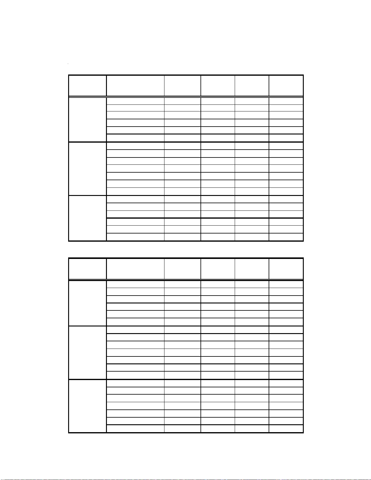
APPENDIX A BLOWER PERFORMANCE TABLES
3 T
ith
LOW
DIRECT DRIVE
CPG036 DOWN SHOT AND HORIZONTAL
CPG036 DIRECT DRIVE DOWN SHOT
SPEED TAP
LOW
MED
HIGH
EXTERNAL STATIC
PRESSURE (ESP)
in w.c.
0.10 1313 1.68 356 748
0.20 1247 1.63 344 786
0.30 1178 1.59 334 832
0.40 1094 1.55 324 869
0.50 1002 1.50 312 913
0.60 919 1.45 296 940
0.10 1471 2.11 454 830
0.20 1400 2.06 440 863
0.30 1354 2.02 432 896
0.40 1271 1.95 416 929
0.50 1188 1.90 398 957
0.60 1083 1.82 378 984
0.70 955 1.74 356 1012
0.30 1470 2.37 510 935
0.40 1390 2.31 492 957
0.50 1310 2.25 476 978
0.60 1206 2.17 454 1000
0.70 1098 2.09 436 1023
0.80 966 1.99 412 1045
STANDARD
CFM
AMPS WATTS RPM
CPG036 DIRECT DRIVE HORIZONTAL
EXTERNAL STATIC
SPEED TAP
LOW
MED
HIGH
NOTES:
Tables represent dry coil wit hout filter, to compensate for filter add 0.08" to measured E.S.P. SCFM
correction for wet coil = 4 %.
on models are shipped from the factory w
PRESSURE (ESP)
in w.c.
0.10 1293 1.72 364 715
0.20 1235 1.67 354 759
0.30 1173 1.62 342 803
0.40 1124 1.58 330 841
0.50 1056 1.54 316 880
0.60 978 1.47 298 913
0.10 1500 2.13 462 808
0.20 1434 2.10 448 838
0.30 1381 2.04 436 869
0.40 1318 2.00 424 902
0.50 1238 1.94 406 929
0.60 1163 1.88 392 951
0.70 1055 1.80 370 990
0.80 936 1.72 350 1017
0.40 1441 2.35 504 940
0.50 1355 2.28 484 962
0.60 1264 2.21 468 989
0.70 1157 2.13 446 1012
0.80 1027 2.03 418 1034
0.90 840 1.90 388 1067
STANDARD
CFM
speed tap set on
25
AMPS WATTS RPM
.
Page 26

APPENDIX A BLOWER PERFORMANCE TABLES
DIRECT DRIVE
CPG048 DOWN SHOT AND HORIZONTAL
CPG048 DIRECT DRIVE DOWN SHOT
SPEED TAP
LOW
MED
HIGH
EXTERNAL STATIC
PRESSURE (ESP)
in w.c.
0.10 1592 2.54 543 815
0.20 1528 2.43 521 858
0.30 1464 2.32 499 901
0.40 1380 2.21 475 930
0.50 1296 2.10 451 959
0.10 1828 3.08 665 892
0.20 1700 2.75 601 924
0.30 1606 2.61 563 966
0.40 1531 2.48 537 990
0.50 1401 2.32 503 1023
0.60 1287 2.22 477 1045
0.70 1123 2.05 441 1073
0.10 1926 3.34 740 937
0.20 1825 3.18 700 965
0.30 1712 3.03 660 989
0.40 1598 2.87 626 1015
0.50 1482 2.76 596 1032
0.60 1357 2.62 564 1049
STANDARD
CFM
AMPS WATTS RPM
CPG048 DIRECT DRIVE HORIZONTAL
EXTERNAL STATIC
SPEED TAP
LOW
MED
HIGH
NOTES:
Tables represent dry coil without filter, to comp ensate f or filt er add 0.08" to measured E.S.P. SCFM
correction fo r wet coi l = 4 % .
4 Ton models are shipped from the factory with speed tap set on MED.
PRESSURE (ESP)
in w.c.
0.10 1612 2.60 554 789
0.20 1548 2.49 532 832
0.30 1484 2.38 510 875
0.40 1400 2.27 486 904
0.50 1316 2.16 462 933
0.10 1846 3.14 676 866
0.20 1718 2.81 612 898
0.30 1624 2.67 574 940
0.40 1549 2.54 548 964
0.50 1419 2.38 514 997
0.60 1305 2.28 488 1019
0.70 1141 2.11 452 1047
0.10 1954 3.43 758 924
0.20 1853 3.27 718 952
0.30 1740 3.12 678 976
0.40 1626 2.96 644 1002
0.50 1510 2.85 614 1019
0.60 1385 2.71 582 1036
STANDARD
CFM
AMPS WATTS RPM
26
Page 27

APPENDIX A BLOWER PERFORMANCE TABLES
DIRECT DRIVE
CPG060 DOWN SHOT
CPG060 DIRECT DRIVE DOWN S HOT
SPEED
TAP
T1
T2
T3
T4
T5
NOTES:
Tables represent dry coil wit hout filter, to compensate for filter add 0.08" to measure d E.S.P. SCFM
correction fo r wet coi l = 4 %. 5 Ton models are sh ipped from the factory wi th speed tap set on T 4.
EXTERNAL STATIC
PRESSURE (ESP)
in w.c.
0.10 1237 1.64 180 638
0.20 1191 1.75 194 682
0.30 1127 1.80 200 715
0.40 1065 1.89 214 753
0.50 994 1.97 220 797
0.10 1437 2.13 248 687
0.20 1384 2.24 254 726
0.30 1312 2.29 262 759
0.40 1245 2.42 280 803
0.50 1185 2.54 294 847
0.10 1988 4.49 558 885
0.20 1942 4.58 574 907
0.30 1882 4.69 582 935
0.40 1847 4.80 600 962
0.50 1784 4.87 612 990
0.60 1762 4.97 626 1008
0.70 1688 5.05 642 1039
0.10 2106 5.14 650 924
0.20 2050 5.26 670 951
0.30 1993 5.32 678 969
0.40 1960 5.47 696 1001
0.50 1920 5.54 706 1021
0.60 1880 5.61 726 1041
0.70 1810 5.73 736 1072
0.80 1760 5.81 750 1093
0.90 1694 5.84 752 1122
0.10 2199 5.87 762 968
0.20 2146 5.96 772 989
0.30 2121 6.06 788 1012
0.40 2066 6.15 804 1039
0.50 2010 6.21 814 1056
0.60 1978 6.32 834 1084
0.70 1919 6.28 830 1102
0.80 1837 6.22 814 1122
0.90 1738 6.04 786 1127
STANDARD
CFM
AMPS WATTS RPM
27
Page 28

APPENDIX A BLOWER PERFORMANCE TABLES
DIRECT DRIVE
CPG060 HORIZONTAL
CPG060 DIRECT DRIVE HORIZONTAL
SPEED
TAP
T1
T2
T3
T4
T5
NOTES:
Tables represent dry coil without filter, to compensate for filter add 0.08" to measured E.S.P. SCFM
correction fo r wet coi l = 4 %. 5 Ton m o dels are ship ped f ro m th e facto ry with speed tap set o n T4.
EXTERNAL STATIC
PRESSURE (ESP)
in w.c.
0.10 1416 1.63 176 588
0.20 1295 1.61 174 621
0.30 1200 1.68 186 660
0.40 1133 1.79 196 704
0.50 1045 1.90 208 753
0.10 1543 2.00 220 627
0.20 1485 2.12 236 671
0.30 1425 2.20 250 698
0.40 1352 2.26 258 748
0.50 1304 2.39 274 786
0.10 2107 4.02 502 797
0.20 2031 4.13 518 819
0.30 1980 4.27 536 858
0.40 1954 4.37 554 880
0.50 1887 4.48 572 913
0.60 1839 4.58 582 940
0.70 1782 4.72 602 968
0.10 2224 4.73 592 832
0.20 2165 4.79 612 860
0.30 2123 4.91 630 891
0.40 2079 5.01 642 913
0.50 2029 5.14 666 946
0.60 1978 5.26 676 969
0.70 1926 5.38 698 1001
0.80 1872 5.48 712 1028
0.90 1817 5.58 722 1056
0.10 2318 5.42 700 874
0.20 2296 5.55 720 903
0.30 2228 5.66 734 929
0.40 2193 5.76 748 950
0.50 2145 5.90 766 979
0.60 2097 5.99 784 1012
0.70 2054 6.10 798 1034
0.80 1991 6.15 810 1050
0.90 1952 6.26 826 1079
STANDARD
CFM
AMPS WATTS RPM
28
Page 29

APPENDIX A BLOWER PERFORMANCE TABLES
BELT DRIVE
STANDARD DOWN SHOT
CPG036 STANDARD BELT DRIVE HORIZONTAL
ESP, In
O
H
2
0.2
0.4
0.6
0.8
1.0
1.2
012345
CFM BHP CFM BHP CFM BHP CFM BHP CFM BHP CFM BHP
1541 0.43 1284 0.32 1024 0.23 714 0.14
1444 0.45 1193 0.33 936 0.24
1111 0.34 806 0.23
744 0.22
CPG048 STANDARD BELT DRIVE HORIZONTAL
ESP, In
O
H
2
0.2
0.4
0.6
0.8
1.0
1.2
012345
CFM BHP CFM BHP CFM BHP CFM BHP CFM BHP CFM BHP
1910 0.67 1612 0.50 133 0 0.37 1030 0.23
1813 0.69 1571 0.54 1222 0.36 989 0.25
1478 0.56 1142 0.32
1107 0.41
TU RNS O PEN
1524 0.32 1340 0.25
16280.4113960.3211710.24900 0.16
TU RNS O PEN
1800 0.47 1556 0.35
20020.6517080.4914380.3611670.22
CPG060 STANDARD BELT DRIVE HORIZONTAL
ESP, In
H
O
2
0.2
0.4
0.6
0.8
1.0
1.2
012345
CFM BHP CFM BHP CFM BHP CFM BHP CFM BHP CFM BHP
24081.0022060.8419820.6818080.5515720.41
2402 1.08 2173 0.89 1943 0.72 1701 0.55 1511 0.43
2153 0.95 1917 0.77 1667 0.59
1888 0.82 1634 0.63
1601 0.67
TU RNS O PEN
24600.9622510.8020730.6518620.51
CPG072 STANDARD BELT DRIVE HORIZONTAL
ESP, In
O
H
2
0.2
0.4
0.6
0.8
1.0
1.2
NOTE
Tables represent dry coil without filter, to comp ensate f or filter add 0.08" to measured E.S.P.
SCF M correctio n for w et coi l = 4 %.
012345
CFM BHP CFM BHP CFM BHP CFM BHP CFM BHP CFM BHP
2765 1.52 2596 1.28 2476 1.09 2327 0.94 2159 0.75 1938 0.59
2650 1.43 2452 1.18 2325 1.00 2070 0.80 1898 0.64
2443 1.29 2251 1.06 2068 0.86 1868 0.71
2258 1.17 2040 0.94 1806 0.73
2021 1.02
TU RNS O PEN
26251.1824861.0223220.8321520.68
29
Page 30

APPENDIX A BLOWER PERFORMANCE TABLES
BELT DRIVE
STANDARD HORIZONTAL
CPG036 STANDARD BELT DRIVE HORIZONTAL
ESP, In
H
O
2
0.2
0.4
0.6
0.8
1.0
1.2
012345
CFM BHP CFM BHP CFM BHP CFM BHP CFM BHP CFM BHP
1541 0.43 1284 0.32 1024 0.23 714 0.14
1444 0.45 1193 0.33 936 0.24
1111 0.34 806 0.23
744 0.22
CPG048 STANDARD BELT DRIVE HORIZONTAL
ESP, In
O
H
2
0.2
0.4
0.6
0.8
1.0
1.2
012345
CFM BHP CFM BHP CFM BHP CFM BHP CFM BHP CFM BHP
1910 0.67 1612 0.50 1330 0.37 1 030 0.2 3
1813 0.69 1571 0.54 1222 0.36 989 0.25
1478 0.56 1142 0.32
1107 0.41
TU RNS O PEN
1524 0.32 1340 0.25
16280.4113960.3211710.24900 0.16
TU RNS O PEN
1800 0.47 1556 0.35
20020.6517080.4914380.3611670.22
CPG060 STANDARD BELT DRIVE HORIZONTAL
ESP, In
H
O
2
0.2
0.4
0.6
0.8
1.0
1.2
012345
CFM BHP CFM BHP CFM BHP CFM BHP CFM BHP CFM BHP
24081.0022060.8419820.6818080.5515720.41
2402 1.08 2173 0.89 1943 0.72 1701 0.55 1511 0.43
2153 0.95 1917 0.77 1667 0.59
1888 0.82 1634 0.63
1601 0.67
TU RNS O PEN
24600.9622510.8020730.6518620.51
CPG072 STANDARD BELT DRIVE HORIZONTAL
ESP, In
O
H
2
0.2
0.4
0.6
0.8
1.0
1.2
NOTE
Tables represent dry coil without filter, to comp ensate f or filter add 0.08" to measured E.S.P.
SCF M correctio n for w et coi l = 4 %.
012345
CFM BHP CFM BHP CFM BHP CFM BHP CFM BHP CFM BHP
26551.3124981.1023060.9220940.7218900.57
2703 1.47 2486 1.20 2263 0.97 2076 0.81
2515 1.34 2272 1.07 2002 0.83
2253 1.16 2028 0.93
TU RNS O PEN
2749 1.18 2573 0.96 2402 0.79
26801.2225441.0623460.8421640.68
30
Page 31

APPENDIX A BLOWER PERFORMANCE TABLES
BELT DRIVE
HIGH STATIC DOWN SHOT
CPG036 HIGH STATIC BELT DRIVE DOWN SHOT
ESP, In
O
H
2
CFM BHP CFM BHP CFM BHP CFM BHP CFM BHP CFM BHP
0.6
0.8
1.0
1.2
1638 0.692 1307 0.519 984 0.362
1307 0.579 1002 0.416
1.4
1002 0.476 717 0.319
1.6
1.8
717 0.379
1638 0.632 1326 0.471 1002 0.317 713 0.192
CPG048 HIGH STATIC BELT DRIVE DOWN SHOT
ESP, In
O
H
2
0.6
0.8
1.0
1.2
1.4
1.6
1.8
012345
CFM BHP CFM BHP CFM BHP CFM BHP CFM BHP CFM BHP
1952 0.876 1622 0.665 1335 0.494 1056 0.345
1897 0.93 1611 0.726 1315 0.543 1008 0.357
1616 0.80 1298 0.588 1007 0.419
1316 0.659 1007 0.46
TU RNS O PEN
450123
1655 0.526 1389 0.395 1103 0.275
1640 0.571 1342 0.426 1035 0.289 775 0.19
TU RNS O PEN
1989 0.769 1712 0.594 1433 0.441
1929 0.788 1662 0.631 1384 0.469 1106 0.329
CPG060 HIGH STATIC BELT DRIVE DOWN SHOT
ESP, In
H
O
2
0.6
0.8
1.0
1.2
1.4
1.6
012345
CFM BHP CFM BHP CFM BHP CFM BHP CFM BHP CFM BHP
2277 1.271 2070 1.048 1852 0.837 1646 0.656
2304 1.387 2089 1.153 1872 0.931 1647 0.722
2104 1.255 1893 1.029 1668 0.811
1912 1.129 1690 0.90
1720 1.00
TU RNS O PEN
2262 1.161 2051 0.948 1851 0.763 1657 0.60
CPG072 HIGH STATIC BELT DRIVE DOWN SHOT
ESP, In
H
O
2
0.6
0.8
1.0
1.2
1.4
1.6
1.8
NOTE
Tables represent dry coil without filter, to comp ensate for filter add 0.08" to measured E.S.P.
SCF M correctio n for w et coi l = 4 %.
012345
CFM BHP CFM BHP CFM BHP CFM BHP CFM BHP CFM BHP
2775 1.762 2638 1.526 2407 1.253 2226 1.045 2011 0.835
2821 1.894 2660 1.668 2407 1.358 2194 1.116 2012 0.923
2696 1.787 2497 1.54 2228 1.235 1977 0.985
2455 1.591 2236 1.346 2013 1.10
2262 1.44 2032 1.20
2069 1.30
TU RNS O PEN
2793 1.645 2575 1.367 2407 1.155 2250 0.963
31
Page 32

APPENDIX A BLOWER PERFORMANCE TABLES
BELT DRIVE - HIGH STATIC HORIZONTAL
CPG036 HIGH STATIC BELT DRIVE HORIZONTAL
ESP, In
H
O
2
0.6
0.8
1.0
1.2
1.4
1.6
1.8
012345
CFM BHP CFM BHP CFM BHP CFM BHP CFM BHP CFM BHP
1458 0.57 1146 0.41 802 0.25
1458 0.63 1139 0.46 782 0.30
1139 0.52 844 0.36
844.3 0.42
CPG048 HIGH STATIC BELT DRIVE HORIZONTAL
ESP, In
O
H
2
0.6
0.8
1
1.2
1.4
1.6
1.8
012345
CFM BHP CFM BHP CFM BHP CFM BHP CFM BHP CFM BHP
1786 0.80 1445 0.59 1115 0.40
1764 0.86 1426 0.64 1107 0.46
1446 0.72 1098 0.50
1099 0.56
TU RNS O PEN
1568 0.45 1266 0.32
1492 0.47 1194 0.34 922 0.23
1476 0.52 1163 0.37 856 0.24
TU RNS O PEN
1894 0.66 1585 0.49
1839 0.71 1532 0.53 1223 0.37
17820.7314770.5511700.39
CPG060 HIGH STATIC BELT DRIVE HORIZONTAL
ESP, In
H
O
2
0.6
0.8
1.0
1.2
1.4
1.6
1.8
012345
CFM BHP CFM BHP CFM BHP CFM BHP CFM BHP CFM BHP
2260 1.26 1983 1.00 1683 0.74
2288 1.38 2009 1.10 1711 0.84
2032 1.21 1741 0.93
1776 1.04
TU RNS O PEN
2215 1.04 1956 0.82 1697 0.62
22401.1519570.9016810.67
CPG072 HIGH STATIC BELT DRIVE HORIZONTAL
ESP, In
O
H
2
0.6
0.8
1.0
1.2
1.4
1.6
1.8
2.0
012345
CFM BHP CFM BHP CFM BHP CFM BHP CFM BHP CFM BHP
2748 1.74 2518 1.44 2255 1.13 1 970 0.8 7
2797 1.87 2562 1.59 2273 1.27 2025 0.99
2556 1.67 2314 1.40 2035 1.11
2342 1.50 2037 1.21
2137 1.35
TU RNS O PEN
2690 1.42 2529 1.20 2263 0.94
27401.6024711.2722461.0219720.79
2219 0.95 1970 0.75
2677 1.29 2486 1.07
NOTE
Tables represent dry coil without filter, to comp ensate f or filter add 0.08" to measured E.S.P.
SCF M correctio n for w et coi l = 4 %.
32
Page 33

MODELS
3 TON
4 TON
APPENDIX B ELECTRICAL DATA
ELECTRICAL DATA
VOLTAGE
(NAMEPLATE)
20 8/230- 60-1 187 2 53 1 1 6.67 7 9 1 1 /4 1.40 DD STD ST ATIC 1/3 2.5
208/230-60-3
46 0-60 - 3 41 4 5 06 1 5.77 38.0 1 1/4 0.80 BD STD STAT IC 1.0 1. 9
57 5-60 - 3 51 8 633 1 3.8 37.0 1 1/4 0.60 BD STD STAT IC 1.5 2.3
20 8/230- 60-1 187 253 1 19.87 109 1 1 /4 1.40 DD STD STATIC 1/2 2.9
208/230-60-3 187 253 1 13.14 83.1
VOLTAGE
LIMITATION
MIN. MAX. QTY RLA LRA QTY HP RLA HP FLA
COMPRESSOR
110.4573.0 1187 253
OUTDOOR
FAN M OTOR
1/4 1.40
11/41.40
INDOOR
MOTOR
APPLICATION
DD STD STATI C 1/ 3 2.5
BD STD STAT IC 1.0 3.8
DD STD STATI C 1/ 2 2.9
BD STD STATIC 1.0 3.8
INDOOR
FAN MOTOR
5 TON
6 TON
46 0-60 - 3 41 4 5 06 1 6.09 41.0 1 1/4 0.80 BD STD STAT IC 1.0 1. 9
57 5-60 - 3 51 8 633 1 4.4 33.0 1 1/4 0.60 BD STD STAT IC 1.5 2.3
20 8/230- 60-1 187 253 1 26.41 134 1 1 /4 1.40 DD STD STATIC 1.0 7.6
DD STD STATI C 1. 0 7.6
208/230-60-3
46 0-60 - 3 41 4 5 06 1 7.76 52.0 1 1/4 0.80 BD STD STAT IC 1.0 1. 9
57 5-60 - 3 51 8 6 33 1 5.71 38.9 1 1/4 0.60 BD STD STAT IC 1.5 2. 3
20 8/2 30-60 - 3 187 253 1 19 123 1 1/ 3 1. 92 BD STD STATI C 1.5 5.0
46 0-60 - 3 41 4 5 06 1 9.70 62.0 1 1/3 1.20 BD STD STAT IC 1.5 2. 5
57 5-60 - 3 51 8 633 1 7.4 50.0 1 1/3 0.90 BD STD STAT IC 1.5 2.3
187 253 1/4 1.401 15.96 110.0 1
BD STD STATIC 1.0 3.8
33
Page 34

APPENDIX C UNIT DIMENSIONS
47 1/2”
73 1/4”
38 13/16”*
74 1/16”
*6 Ton - 42 13/16
48 3/16”
11”
4 7/8”
17” 7 3/8”
RETURN
12”
SUPPLY
6 1/4”
Horizontal Discharge
NOTE
For horizontal discharge, remove the
supply and return duct covers and place
them over the vertical discharge return and
supply openings. Install with insulation
facing up, using the longer screws
provided in the literature package.
25”
19 7/16”
RETURN
5 7/8”
SUPPLY
8 3/16”
DRAIN
THRU CURB
LOCATION
27 3/8”
47 1/2”
BOTTOM VIEW OF UNIT
Vertical Discharge
EMBOSS
FOR
THRU THE
BASE
UTILITIES
4 1/2”
7 1/2”
34
Page 35

APPENDIX D WIRING DIAGRAMS
35
Page 36

COMP
CPG036(48)0451D SINGLE PHASE 240V/60HZ DIRECT DRIVE
HIGH VOLTAGE!
DISCONNECT ALL POWER BEFORE SERVICING OR INSTALLING THIS
UNIT. MULTIPLE POWER SOURCES MAY BE PRESENT. FAILURE TO
DO SO MAY CAUSE PROPERTY DAMAGE, PERSONAL INJURY OR DEATH.
YL
RD
BK
PU
PU
BK
BK
BL
T2
T1
YL
L2
L1
C
RD
GND
BR
CM
BL
BK
208-240/1/60
SEE NOTE 5
PU
EM
3 SPEE D
BL
RD
BK
PU
BR
BC
RD
ALTERNATE
MOTOR
6-WIRES
SEE NOTE 6 & 7
PU
LS
RD
RD
321
208
TR
24V
BL
BL
240
GR
FOR
SMOKE/FIRE
DETECTOR
REPLACE
JUMPER
C
PK
S1
BL
EM
3 SPEED
BR
BC
PU
SEE NOTE 7
PK
TB1
S2
BK
RD
OR
ALS
IIC
PU
PS
PU
YL
GR
YL
YL
YL
BR
BL
RD
BK
PU
GAS VALVE
VM
RS
W. R.
GV
NOTE 4
PLF
3 6
2
5
1 4
YL
(ALT.) HONEYWELL
GAS VALVE
MV
PU
MV
BL
BL
GR
GV
IGN
FS
BL
YL
BK
YL/PK
TB1
Y2
RG
C
Y1W1
SEE NOTE 8
GREEN JUMPER
RD
RD
OR
RD
BK
BR
RCCF
FH
BL/PK
C
RD
YL
208-240/1/60 0140L00510 REV A
Wiring is subject to change. Always refer to the wiring diagram on the unit for the most up-to-date wiring.
36
YL RD
YL
LPS
HPS
Page 37

CPG036(48)0451D SINGLE PHASE 240V/60HZ DIRECT DRIVE
HIGH VOLTAGE!
DISCONNECT ALL POWER BEFORE SERVICING OR INSTALLING THIS
UNIT. MULTIPLE POWER SOURCES MAY BE PRESENT. FAILURE TO
DO SO MAY CAUSE PROPERTY DAMAGE, PERSONAL INJURY OR DEATH.
L1
C
T1
C
HEAT
EM
PCB
COOL
F
4
5
IIC
9
7
GR
TO THERMOSTAT
TERMINAL BLOCK
STAT US LIGHT
ON
OFF
1 BLINK
2 BLINKS
3 BLINKS
4 BLINKS
5 BLINKS
6 BLINKS
SUPP LY VOLTAGE
208-240/1/60
R
S
FC
2
TB1
FS
3
6
8
10
12
11
W Y2
IGN
LS
ALS
PS
LPS
HPS
Y1
INSTALLER/SERVICEMAN
EQUIP. STATUS
NORMAL O PERATIO N
NO POWER OR
INTERN AL CONTROL
FAULT
IGNITION FAILURE
OR
OPEN ROLLOUT
SWITCH
OR
OPEN AUX. LIMIT
SWITCH
PRESSURE SWITCH
OPEN
WITHOUT INDUCER ON
OPEN LIMIT SWITCH
FALSE FLAME SENSED
COMPRESSOR
OUTPUT DELAY
FS
TR
RS
L2
COM
PONENT LEGEND
AUXILIARY LIMIT SWITCH
ALS
COMP
COMPRESSOR
C
C
H
F
CM
PCB
VMLI
DI
13
IIC
GV
C
NOTE
4
C
TB1
GAS FLOW
GAS PRESSURE
GAS VALVE
FLAME SEN SO R
FLAME ROLLOUT
BAD SWITCH
AUX. LIMIT OPEN
PRESSURE SWITCH
PRESSURE SWITCH
MAIN LIMIT OPEN
BAD SWITCH
3 MIN . COMP.
PLF
CHECK
-
CHECK
CHECK
56
321
CM CONDENSER MOTOR
CONTACTOR
C
L2
4
EVAPORATOR MOTOR
EM
F
FUSE
FLAME SENSOR
FS
EQUIPMENT GROUND
GND
GV
GAS VALVE
HPS HIGH PRESS URE S WITCH
INTEGRATED IGNITION CO NTRO L
IIC
IGNITOR
IGN
LS LIMIT SWITCH
LPS LOW PRESSURE SWITCH
FEMALE PLUG/CONNECTOR
PLF
PRESSURE SWITCH
PS
RUN CAPACITOR FOR CONDENSER FAN
RCCF
ROLLOUT SWITCH
RS
TERMINAL BLOCK (24V SIGNAL)
TB1
TR
TRANSFORMER
VENT MOTOR
VM
VENT MOTOR RELAY
VMR
BC
BLOWE R CAPACITOR
NO
TES
1. REPLACEMENT WIRE MUST BE THE SAME
SIZE AND TYPE OF INSULATION AS ORIGINAL.
(USE COPPER CONDUCTOR ONLY).
2. FOR 208 VOLT TRANSFORMER OPERATION
MOVE BLACK WIRE FROM TERMINAL 3 TO
TERMINAL 2 ON TRANSFORMER.
3. FOR DIFF ERENT THAN FACTORY SPEED TAP.
CHANGE COOLING SPEED AT COOL
TERMI NAL. CHA NGE HE ATI N G SPE E D AT
HEAT TERMINAL ON CONTROL BOARD
SPEED MOTOR
3
RD - LOW SPEED
BL - MED. SPEED
BK - HIGH SPEED
4. ACCESSOR Y ECONO MIZER PLUG ADJACENT
TO BL OWER H OUSING IN RETURN A IR
COMPARTMENT. REMOVE MALE PLUG AND
ATTACH FEMALE PLUG TO ECONOMIZER
ACCESSORY.
5. USE COP PER CONDUCTORS ONLY.
6. PURPLE WIRE CONNECTS TO TRANSFORMER
(PIN 1).
7. SPEED TAP TERMINATIONS S HOWN ON
DIAGRAM ARE REPRESENTATIVE, BU T ACTUAL
FA CTORY SETTING MAY BE DIFFEREN T BASED
ON HEATING VALUE AND CAPACITY OF UNIT.
8. TO RUN DIFFERENT SP EED FOR HEATING AND
COOLING, DISCONNECT GEEEN JUMPER FROM
"COOL" TERMINAL AND REPLACE WITH
APPROPRIATE SPEED TAP. THEN PLACE
DISCONNECTED END OF JUMPER ON
"UNUSED" TERMINAL LEFT OP EN BY MOVING
THE SPEED TAP.
SEE UNIT RATING PLATE FOR TYPE AND SIZE OF
OVERCURRENT PROTECTION.
USE NEC CLASS 2 WIRE.
208-240/1/60 0140L00510 REV A
BK BLA CK
BL BLUE
BR BROWN
GR GREEN
OR ORANGE
PK PINK
PU PURPLE
RD RED
WH WHITE
YL YELLOW
BL/PK BLUE WITH PINK STRIP
YL/PK YELLOW WITH PINK STRIP
FAC TORY WIRING
LINE VOLTAGE
LOW VOLT AGE
OPTIONAL
HIGH VOLTAGE
FIELD WIRING
HIGH VOLTAGE
LOW VOLTAGE
E CODE
WIR
THERMOSTAT
FIELD WIRING
N
O ECONOMIZER
W
G
R
Y1
Y/Y2
C
TB1
TH ECONOMIZER OPTION
WI
W
G
R
Y1
Y/Y2
C
TB1
2
W
G
R
Y1
Y/Y2
C
TB1
WH
GR
RD
YL
BL
WH
GR
RD
YL
BL
STAGE COOLING
WH
GR
RD
YL
PK
BL
W
G
R
Y
C
STAT
W
G
R
Y
C
STAT
W
G
R
Y1
Y2
C
STAT
Wiring is subject to change. Always refer to the wiring diagram on the unit for the most up-to-date wiring.
37
Page 38
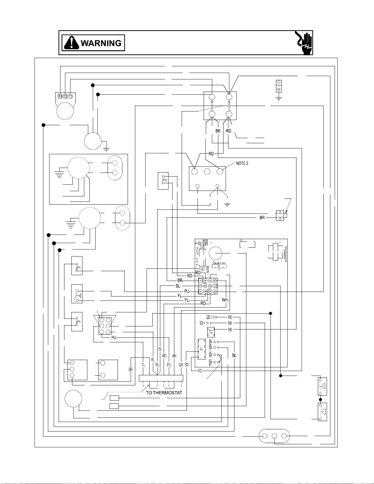
(
COMP
CPG036(048)0901D SINGLE PHASE 240V/60HZ DIRECT DRIVE
HIGH VOLTAGE!
DISCONNECT ALL POWER BEFORE SERVICING OR INSTALLING THIS
UNIT. MULTIPLE POWER SOURCES MAY BE PRESENT . FAILURE TO
DO SO MAY CAUSE PROPERTY DAMAGE, PERSONAL INJURY OR DEATH.
YL
RD
BK
PU
PU
BK
BK
BL
T2
T1
YL
L2
L1
C
RD
GND
BR
CM
BL
BK
208-240/1/60
SEE NOTE 5
PU
BR
BK
BL
RD
PU
EM
3 SPEED
RD
ALTERNATE
MOTOR
6-WIRES
SEE NOTE 6 & 7
BC
PU
LS
RD
RD
C
PK
321
208
240
TR
24V
BL
BL GR
FOR
SMOKE/FIRE
DETECTOR
REPLACE
JUMPER
S1
BL
EM
3 SPEED
BR
BC
PU
SEE NOTE 7
TB1
PK
S2
BK
RD
OR
ALS
IIC
PU
PS
PU
YL
GR
YL
YL
YL
BR
RD
BK
PU
BL
GAS VALVE
VM
RS
W. R.
GV
NOTE 4
PLF
PU
BL
SEE
NOTE 9
RD
GR
3 6
2
5
1 4
YL
ALT.) HONEYWELL
GAS VAL VE
MV
GV
MV
BL
FS
IGN
BK
YL
BL
BK
YL/PK
YL/PK
TB1
Y2
W2
C
WH
RGY1W1
SEE NOTE 8
GREEN J UMPER
RD
RD
OR
BL/PK
C
BR
F
RCCF
H
208-240/1/60 0140L00506 REV A
Wiring is subject to change. Always refer to the wiring diagram on the unit for the most up-to-date wiring.
38
YL RD
YL
LPS
HPS
RD
YL
Page 39

CPG036(048)0901D SINGLE PHASE 240V/60HZ DIRECT DRIVE
HIGH VOLTAGE!
DISCONNECT ALL POWER BEFORE SERVICING OR INSTALLING THIS
UNIT. MULTIPLE POWER SOURCES MAY BE PRESENT. FAILURE TO
DO SO MAY CAUSE PROPERTY DAMAGE, PERSONAL INJURY OR DEATH.
L1
C
T1
C
HEAT
EM
PCB
COOL
F
4
5
IIC
9
7
GR
TO THERMOSTAT
TERMINAL BLOCK
STATUS LIGHT
ON
OFF
1 BLINK
2 BLINKS
3 BLINKS
4 BLINKS
5 BLINKS
6 BLINKS
SUPPLY VOLTAGE
208-240/1/60
R
S
FC
2
TB1
FS
3
6
8
12
10
11
W Y2
IGN
LS
ALS
PS
LPS
HPS
Y1
INSTALLER/SER VICEMAN
EQUIP. STATUS
NORMAL OPERATION
NO POWER OR
INTERNAL CO NT ROL
FAULT
IGNITION FAILURE
OR
OPEN ROLLOUT
SWITCH
OR
OPEN AU X. LIMI T
SWITCH
PRESSURE SWITCH
OPEN
WITHOUT INDUCER ON
OPEN LIMIT SWITCH
FALSE FLAME SENSED
COMPRE SSOR
OUTPUT DE L AY
HC
F
13
TR
FS
RS
C
C
CM
PCB
VMLI
DI
GV
C
NOTE
4
PLF
TB1
CHECK
-
GAS FLOW
GAS PRESSURE
GAS VALVE
FLAME SENSOR
FLAME ROLLOUT
BAD SWITCH
AUX. LIMIT OPEN
CHECK
PRESSURE SWITCH
CHECK
PRESSURE SWITCH
MAIN LIMIT OPEN
BAD SWITCH
3 MIN. COMP.
L2
L2
IIC
56
4
321
C
OMPONENT LEGEND
AUXILIARY LIMIT SWITCH
ALS
COMP
COMPRESSOR
CM CO NDENSER MOTOR
CONTACTOR
C
EM
EVAPORATOR MOTOR
F
FUSE
FLAME S ENSOR
FS
EQUIPMENT G RO UND
GND
GAS VALVE
GV
HPS HIGH PRESSURE SWITCH
IIC
INTEGRATED IGNITION CONTROL
IGN
IGNITOR
LS LIMIT SWITCH
LPS LOW PRESSURE SWITCH
PLF
FEMALE PLUG/CONNECTOR
RUN CAPACITOR FOR CONDENSER FANRCCF
PRESSURE SWITCH
PS
ROLLOUT SWITCH
RS
TER MINAL B L OCK (24 V SIGNAL)
TB1
TR TRANSFORMER
VENT MOTOR
VM
VMR
VENT MOTOR RELAY
BLOWER CAPACITOR
BC
OTES
N
1. REPLACEMENT WIRE MUST BE THE SA ME
SIZE AND TYPE OF INSULA TION A S ORIGINAL.
(USE COPPER CONDUCTOR ONLY).
2. FOR 20 8 V OLT TRANSFORMER OPERATION
MOVE BLACK WIRE FROM TERMINAL 3 TO
TERMIN AL 2 ON TRANSFO RM E R.
3. FOR DIFFERENT THAN FACTORY SPEED TAP.
CHANGE COOLING SPEED AT COOL
TERMINAL. C H ANGE HEATING SPEED AT
HEAT TERM IN AL ON CONTROL BOARD
SPEED MOTOR
3
RD - LOW SPEED
BL - MED. SPEED
BK - HIGH SPEED
4. ACCESSO RY ECO NOM IZER PLUG A DJACENT
TO BLOWER HOUSING IN RETURN AIR
COMPARTMENT. REMOVE MALE PLUG AND
ATTACH FEM ALE PLUG TO ECONOMI ZER
ACCESSORY.
5. USE COPPER C ONDUCTORS ONLY.
6. PURPLE WIRE CONNECTS TO TRANSFORMER
(PIN 1).
7. SPEE D TAP TERMINATIONS SHOW N ON
DIAGRAM ARE REPRESENT ATIVE, BUT ACTU AL
FACTORY SETTING MAY BE DIFFERENT BASED
ON HEATING VALUE AND CAPACITY OF UNIT.
8. TO RUN DIFFERENT SPEED FOR HEATING AND
COOLING, DISCONNECT GEEEN JUMPER FROM
"COOL" T ERMINAL AND REPLACE WITH
APPROPRI ATE SPEED TAP. THEN PLACE
DISCONNECTED END OF JUMPER ON
"UNUSED" TERMINAL LEFT OPEN BY MOVING
THE SPEED TAP.
SEE UNIT RATING PLATE FOR TYPE AND SIZE OF
OVERCURRENT PROTECTION.
USE NEC CLASS 2 WIRE.
9. FOR LOW STAGE OPERATION ONLY, REMOVE
WHITE JUMP ER . FO R 2 STAGE OPER ATION,
REMOVE JUMPER AND CONNECT W2 TO W1
ON THERMOSTAT.
208-240/1/60 0140L00506 REV A
FACTORY WIRING
LINE VOLTAGE
LOW VOLTAGE
OPTIONAL
HIGH VOLTAGE
FIELD WIRING
HIGH VOLTAGE
LOW VOLTAGE
W
BK BLACK
BL BLUE
BR BROWN
GR GREEN
OR ORANGE
PK PINK
PU PURPLE
RD RED
WH WHITE
YL YELLOW
BL/PK BLUE WITH PINK STRIP
YL/PK YELLOW WITH PINK STRIP
IRE CODE
THERMOSTAT
FIELD WIRING
ECONOMIZER
NO
W
G
R
Y1
Y/Y2
C
TB1
ECONOMIZER OPTION
WITH
W
G
R
Y1
YL
Y/Y2
C
TB1
2
STAGE COOLING
W
G
R
Y1
Y/Y2
C
TB1
WH
GR
RD
YL
BL
WH
GR
RD
BL
WH
GR
RD
YL
PK
BL
W
G
R
Y
C
STAT
W
G
R
Y
C
STAT
W
G
R
Y1
Y2
C
STAT
Wiring is subject to change. Always refer to the wiring diagram on the unit for the most up-to-date wiring.
39
Page 40

BR
PU
BK
CPG0060*1D SINGLE PHASE 240V/60HZ DIRECT DRIVE
HIGH VOLTAGE!
DISCONNECT ALL POWER BEFORE SERVICING OR INSTALLING THIS
UNIT. MULTIPLE POWER SOURCES MAY BE PRESENT. FAILURE TO
DO SO MAY CAUSE PROPERTY DAMAGE, PERSONAL INJURY OR DEATH.
YL
RD
BK
PU
BK
BL
COMP
T2
T1
L2
L1
C
RD
GND
YL
POWER SUPPLY
240/1/60
SEE NOTE 6
BR WH
BL
CM
BL
NOTE 3 & 7
PU
YL
PU
GAS VALVE
TB1
WH
YL
VM
ALS
PS
RS
W. R.
OR
OR
1
NOTE 4
GV
WH
BK
RD
GEMLC
N
YL
PU
WH
BR
YL
WH
PU
BR
PU
YL
YL
(ALT.) HONEYWELL
GAS VALVE
PU
BL
BL
BK
BL
BR
3 6
2
1 4
YL
5
PLF
MV
MV
GR
5
GR
GV
FS
IGN
YL/PK
YL
YL
WH
PU
YL/PK
LPS
HPS
BL
1 23
C
LS
RD
RD
BL
20
8
TR
GR
24V
24
3
0
PK
BK
2
1
VMR
BL
WH
BL
OR
PK
BL
RD
SEE
NOTE 6
YL
TB1
S1
S2
SMOKE/FIRE
DETECTOR
REPLACES
JUMPER
WIRE
BL
G
Y1
Y
W
W2
C
R
WH
YL
RD
TB1
SEE
NOTE 8
OR
YL
RD
BR
RCCF
F
HC
240/1/ 60 0140L00429 REV B
Wiring is subject to change. Always refer to the wiring diagram on the unit for the most up-to-date wiring.
40
Page 41

CPG0060*1D SINGLE PHASE 240V/60HZ DIRECT DRIVE
HIGH VOLTAGE!
DISCONNECT ALL POWER BEFORE SERVICING OR INSTALLING THIS
UNIT. MULTIPLE POWER SOURCES MAY BE PRESENT. FAILURE TO
DO SO MAY CAUSE PROPERTY DAMAGE, PERSONAL INJURY OR DEATH.
L1
C
T1
NOTE 6
L1
F
4
5
IIC
9
7
GR
TO THERMOSTAT
TERMINAL BLOCK
STATUS LIGHT
ON
OFF
1 BLINK
2 BLINKS
3 BLINKS
4 BLINKS
5 BLINKS
6 BLINKS
VM
321
L2
OMPONENT LEGEND
C
ALS
COMP
CM CONDENSER MOTOR
C
L2
EM
FS
GND
GV
HPS
IIC
IGN
LS LIMIT SWITCH
PLF
PS
RCCF
RS
L2
TB1
IIC
TR TRANSFORMER
VM
VMR
NOTES
1. REPLACEMENT WIRE MUST BE THE SAME
SIZE AND TYPE OF INSULATION AS ORIGINAL.
(USE COPPER CONDUCTOR ONLY).
2. FOR 208 VOLT TRANSFORMER OPERATION
MOVE BLACK WIRE FROM TERMINAL 3 TO
TERMINAL 2 ON TRANSFORMER.
3. FOR DIFFERENT THAN FACTORY SPEED TAP.
CHANGE COOLING SPEED AT MOTOR T4 AND
T5 TERMINALS. CHANGE HEATING SPEED AT
MOTO R T1. T2, AN D T3 TE RMINALS
4
56
4. ACCESSORY ECONOMIZER PLUG ADJACENT
TO BLOWER HOUSING IN RETURN AIR
COMPARTMENT. REMOVE MALE PL UG AND
ATTACH FEMALE PLUG TO ECONOMIZER
ACCESSORY.
5. USE COPPER CONDUCTORS ONLY.
6. L1 AND L2 ON ICC CONTROL IS 24V INPUT.
7. SPEED TAP TERMINATIONS SHOWN ON
DIAGRAM ARE REPRESENTATIVE, BUT
ACTUAL FACTORY SETT INGS M A Y BE
DIFFERENT BASED ON THE HEATING VALUE
OF THE UNIT.
8. FOR LOW ST AGE OPERATION ONLY, REMOVE
WHITE JUMPER. FOR 2 STAGE OPERATI ON,
REMOVE JUMPER AND CONNECT W2 TO W2
ON THERMOSTAT.
SEE UNIT RATING PLATE FOR TYPE AND SIZE OF OVER
240/1/60 0140L00429 REV B
AUXILIARY LIMIT SWITCH
COMPRESSOR
CONTACTOR
EVAPORATOR MOTOR
FUSEF
FLAME SENSOR
EQUIPMEN T GROUND
GAS VALVE
HIGH PRESSURE SWITCH
INTEGRATED IGNITION CONTROL
IGNITOR
LOW PRESS URE SWIT CHLPS
FEMALE PLUG/CONNECTOR
PRESSURE SWITCH
RUN CAPACITOR FO R CO MPRESSOR/FAN
ROLLOUT SWITCH
TERMINAL BLOC K (24V S IGNAL)
VENT MOTOR
VENT MOTOR RELAY
C
OOLING SPEED (YELLOW WIRE)
T3 - LOW SPEED
T4 - HIGH SPEED
HEATING SPEED (WHITE WIRE)
T1 - LOW SPEED (070)
T2 - MED. SPEED
T5 - HIGH SPEED (140)
USE NEC CLASS 2 WIRE.
CURRENT PROTECTION .
BK BLACK
BL B LUE
BR BROWN
GR GREEN
OR ORANGE
PK PINK
PU PURPLE
RD RED
WH WHITE
YL YELLOW
BL/PK BLUE WITH PINK STRIP
YL/PK YELLOW WITH PINK STRIP
SUPPLY VOLTAGE
240/1/60
R
C
S
HC
C
L
N
EM
C
CM
VMR
31
2
13
IGN
TR
NOTE 6
TB1
FS
CEM
TB1
FS
C
H
D1
LS
3
6
ALS
PS
VMR
RS
TB1
GV
8
10
12
C
11
LPS
W1
W2
HPS
Y
Y1
Y2
TB1
NOTE
4
PLF
C
INSTALLER/SERVIC EMAN
EQUIP. STATUS
NORMAL OPERATION
NO POWER OR
INTERNAL CONTROL
FAULT
IGNITION FAILURE
OR
OPEN ROLLOUT
SWITCH
OR
OPEN AUX. LIMIT
SWITCH
PRESSURE SWITCH
OPEN
WITHOUT INDUC ER ON
OPEN LIMIT SWITCH
FALSE FLA ME S ENSED
COMPRESSOR
OUTPUT DELAY
CHECK
-
GAS FLOW
GAS PRESSURE
GAS VALVE
FLAME SENSOR
FLAME ROLLOUT
BAD SWITCH
AUX. LIMIT OPEN
CHECK
PRESSU RE SWI TCH
CHECK
PRESSU RE SWI TCH
MAIN LIMIT OPEN
BAD SWITCH
3 MIN. COMP.
FACTORY WIRING
LINE VOLTAGE
LOW VOLTAGE
OPTIONAL
HIGH VOLTAGE
FIELD WIRING
HIGH VOLTAGE
LOW VOLTAGE
ODE
WIRE C
THERMOSTAT
FIELD WIRING
NO ECO
NOMIZER
W
G
R
Y1
Y/Y2
C
TB1
TH ECONOMIZER OPTION
WI
W
G
R
Y1
Y/Y2
C
TB1
W
G
R
Y1
Y/Y2
C
TB1
WH
GR
RD
YL
BL
WH
GR
RD
YL
BL
2 STAGE COOLIN
WH
GR
RD
YL
PK
BL
W
G
R
Y
C
STAT
W
G
R
Y
C
STAT
G
W
G
R
Y1
Y2
C
STAT
Wiring is subject to change. Always refer to the wiring diagram on the unit for the most up-to-date wiring.
41
Page 42

CPG060*3D THREE PHASE 208-230V/60HZ DIRECT
(
HIGH VOLTAGE!
DISCONNECT ALL POWER BEFORE SERVICING OR INSTALLING THIS
UNIT. MULTIPLE POWER SOURCES MAY BE PRESENT . FAILURE TO
DO SO MAY CAUSE PROPERTY DAMAGE, PERSONAL INJURY OR DEATH.
YL
RD
BK
PU
BK
T2 T3
T1
YL
COMP
PU
BR
BK
BL
L2
L1
C
L3
OR
BK
POWER SUPPLY
240/3/60
SEE NOTE 5
RD
GND
BR WH
BL
YL
CM
BL
GEMLC
WH
PU
OR
WH
PU
BR
OR
15
WH
YL
ALS
PU
PS
PU
YL
YL
NOTE 4
PLF
RS
PU
W. R.
GAS VALVE
ALT.) HONEYWELL
GAS VAL VE
PU
GV
BL
BL
VM
BK
WH
BL
BR
BK
GR
N
YLBR
YL
NOTE 3 & 7
3 6
2
5
1 4
YL
MV
MV
BR
TB1
GR
GV
IGN
FS
RD
BK
LS
RD
RD
321
208
TR
24V
GR
240
PK
C
BL
VMR
3
2
1
OR
BL
YL RD
WH
BK
BL
OR
GR
YL
YL
YL
BL
SEE
NOTE 6
BL
RGY1 W
C
Y2
W2
TB1
SEE
NOTE 8
WH
YL
RD
PK
S1
TB1
S2
IIC
FOR
SMOKE/FIRE
DETECTOR
REPLACE
JUMPER
YL/PK
LPS
BL/PK
HPS
OR
YL
WH
BR
FC
RD
230/3/ 60 0140L 00 9 80 REV A
Wiring is subject to change. Always refer to the wiring diagram on the unit for the most up-to-date wiring.
42
Page 43

CPG060*3D THREE PHASE 208-230V/60HZ DIRECT DRIVE
HIGH VOLTAGE!
DISCONNECT ALL POWER BEFORE SERVICING OR INSTALLING THIS
UNIT. MULTIPLE POWER SOURCES MAY BE PRESENT. FAILURE TO
DO SO MAY CAUSE PROPERTY DAMAGE, PERSONAL INJURY OR DEATH.
L1
C
T1
NOTE 6
L1
F
4
5
IIC
9
7
GR
TO THERMOSTAT
TERMINAL BLOCK
STATUS LIGHT
ON
OFF
1 BLINK
2 BLINKS
3 BLINKS
4 BLINKS
5 BLINKS
6 BLINKS
SUPPLY VOLTAGE
240/3/60
T2
T1
T3
L
N
EM
TB1
FS
H
C
D1
3
6
8
10
W Y2
W2
INSTALLER/SERVICEMAN
T2
FC
31
C
T3
C
CM
2
TR
IGN
FS
VMR
LS
ALS
RS
PS
12
LPS
11
Y1
EQUIP. STATUS
NORMAL OPERATION
NO POWER OR
INTERNAL CONTROL
IGNITION FAILURE
OPEN ROLLOUT
OPEN AUX. LIMIT
PRESSURE SWITCH
WITHOUT INDUCER ON
OPEN LIMIT SWITCH
FALSE FLAME SENSED
COMPRESSOR
OUTPUT D EL AY
FAULT
OR
SWITCH
OR
SWITCH
OPEN
HPS
C
L2 L3
VMR
3
NOTE 6
1
2
EM
3
4
5
TB1
NOTE 3
GV
C
NOTE 4
PLF
TB1
CHECK
-
GAS FLOW
GAS PRESSURE
GAS VALVE
FLAME SENSOR
FLAME ROLLOUT
BAD SWITCH
AUX. LIM IT O PEN
CHECK
PRESSURE SWITCH
CHECK
PRESSURE SWITCH
MAIN LIMIT OPEN
BAD SWITCH
3 MIN. COMP.
L3
VM1
L2
IIC
C
56
4
321
NENT LEGEND
COMPO
AUXILIARY LIMIT SWITCH
ALS
COMP
COMPRE SSOR
CM CONDENSER MOTOR
C
CONTACTOR
EVAPORATOR MOTOR
EM
F
FUSE
FC
FAN CAPACITOR
FS
FLAME SENSOR
GND
EQUIPMENT GROUND
GV
GAS VALVE
HPS HIGH PRESSURE SWITCH
IIC
INTEGRATED IGNITION CONTROL
IGN
IGNITOR
LS LIMIT SWITCH
LPS LOW PRESSURE SWITCH
FEMALE PLUG/CONNECTOR
PLF
PRESSURE S WIT CH
PS
ROLLOUT SWITCH
RS
TERMINAL BLOCK (24V SIGNAL)
TB1
TR TRANSFORMER
VENT MOTOR
VM
VMR
VENT MOTOR RELAY
S
NOTE
1. REPLACEMENT WIRE MUST BE THE SAME
SIZE AND TYPE O F INS ULATION AS O RIGINAL.
(USE COPPER CONDUCTOR ONLY).
2. FOR 208 VOLT TRANSFORMER OPERATION
MOVE BLACK WIRES FROM TERMINAL 3 TO
TERMINAL 2 ON TRANSFORMER.
3. FOR DIFFERENT THAN FACTORY SPEED TAP.
CHANGE COOLING SPEED AT M OTOR T3 A ND
T4 TERMINALS. CHANGE HEATING SPEED AT
MOTOR T1. T2, AND T5 TERMINALS
COOLING SPEED (YELLOW WIRE)
T3 - LOW SPEED
T4 - HIGH SPEED
EATING SPEED (WHITE WIRE)
H
T1 - LOW SPEED (070)
T2 - MED. SPEED
T5 - HIGH SPEED (140)
4. ACCESSORY ECONOMIZER PLUG ADJACENT
TO BLOWER HOUSING IN RETURN AIR
COMPARTMENT. REMOVE MALE PLUG AND
ATTACH FEMALE PLUG TO ECONOMIZER
ACCESSORY.
5. USE COPPER CONDUCTORS ONLY.
6. L1 AND L2 ON ICC CONTROL IS 24V INPUT.
7. SPEED TAP TERMINATIONS SHOWN ON
DIAGRAM ARE REPRESENTATIVE, BUT
ACTUAL FACTORY SETTINGS MAY BE
DIFFERENT BASED ON THE HEATING VALUE
OF THE UNIT.
8. FOR LOW STAGE OPERATION ONLY, REMOVE
WHITE JUMPER. FOR 2 STAGE OPERATION,
REMOVE JUMPER AND CONNECT W2 TO W2
ON THERMOSTAT.
USE NEC CLASS 2 WIRE.
SEE UNIT RATING P L AT E FOR TYPE AND SIZ E OF OV E R
CURREN T PR OTECTION
230/3/60 0140L00980 REV A
FACTORY WIRING
LINE VOLTAGE
LOW VOLTAGE
OPTIONAL
HIGH VOLTAGE
FIELD WIRING
HIGH VOLTAGE
LOW VOLTAGE
E
WIRE COD
BK BLACK
BL BLUE
BR BROWN
GR GREEN
OR ORANGE
PK PINK
PU PURPLE
RD RED
WH WHITE
YL YELLOW
BL/PK BLUE WITH PINK STRIP
YL/PK YELLOW WITH PINK STRIP
THERMOSTAT
FIELD WIRING
NO
ECONOMIZER
2 STAGE
WH
GR
RD
YL
BL
WH
GR
RD
YL
BL
COOLING
WH
GR
RD
YL
PK
BL
W
G
R
Y1
Y/Y2
C
TB1
W
ITH ECONOMIZER OPTION
W
G
R
Y1
Y/Y2
C
TB1
W
G
R
Y1
Y/Y2
C
TB1
W
G
R
Y
C
STAT
W
G
R
Y
C
STAT
W
G
R
Y1
Y2
C
STAT
Wiring is subject to change. Always refer to the wiring diagram on the unit for the most up-to-date wiring.
43
Page 44

COMP
CPG036(048)*3D THREE PHASE 208-230V/60HZ DIRECT DRIVE
HIGH VOLTAGE!
DISCONNECT ALL POWER BEFORE SERVICING OR INSTALLING THIS
UNIT. MULTIPLE POWER SOURCES MAY BE PRESENT. FAILURE TO
DO SO MAY CAUSE PROPERTY DAMAGE, PERSONAL INJURY OR DEATH.
YL
RD
BK
PU
PU
BK
BK
BL
T2
T1
T2
T3
YL
L2
L1
L2
C
L3
RD
GND
BR
BK
BK
BL
RD
BR
RD
PU
BL
RD
PU
PU
GAS VALVE
EM
3 SPEED
BK
ALS
PS
RS
W. R.
GV
VM
CM
BR
RD
ALTERNATE
MOTOR
6-WIRES
SEE NOTE 6 & 7
EM
3 SPEED
SEE NOTE 7
PU
YL
YL
NOTE 4
PLF
3 6
2
1 4
(ALT.) HONEYWELL
GAS VALVE
PU
BL
BL
RD
BK
YL
BR
PU
MV
MV
BL
BK
POWERSUPPLY
208-240/3/60
SEE NOTE 5
PU
BC
PU
LS
C
RD
PK
RD
208
TR
24V
BL
BL
240
321
FOR
SMOKE/FIRE
GR
DETECTOR
REPLACE
JUMPER
YL RD
S1
BC
PK
TB1
S2
OR
IIC
GR
YL
YL
GR
5
YL
BL
BK
GV
IGN
FS
TB1
Y2
C
RGY1W1
RD
OR
SEE NOTE 8
GREEN JUMPER
RD
YL/PK
BL/PK
FC
BR
F
C
LPS
HPS
RD
208-240/3/60 0140L00512 REV A
Wiring is subject to change. Always refer to the wiring diagram on the unit for the most up-to-date wiring.
44
Page 45

L1
C
T1
T1
HEAT
EM
PCB
COOL
F
4
5
IIC
9
7
GR
TO THERMOSTAT
TERMINAL BLOCK
STA TU S LIGHT
ON
OFF
1 BLINK
2 BLINKS
3 BLINKS
4 BLINKS
5 BLINKS
6 BLINKS
CPG036(048)*3D THREE PHASE 208-230V/60HZ DIRECT DRIVE
SUPPLY VOLTAGE
208-240/3/60
T2
T3
TB1
FS
3
6
8
10
W Y2
INSTALLER/SERVICEMAN
T2
FC
FC
12
11
NORMAL OP ERA TION
INTERNAL CONTROL
IGNITION FAILURE
OPEN AUX. LIMIT
PRESSURE SWITCH
WITHOUT INDUCER ON
OPEN LIM IT SWITCH
FA LSE FL AM E SEN SED
OUTPUT DELAY
CM
2
IGN
LS
ALS
PS
LPS
HPS
Y1
EQUIP . STA TU S
NO POWER OR
FAULT
OR
OPEN R OLLOUT
SWITCH
OR
SWITCH
OPEN
COMPRESSO R
FS
HIGH VOLTAGE!
DISCONNECT ALL POWER BEFORE SERVICING OR INSTALLING THIS
UNIT. MULTIPLE POWER SOURCES MAY BE PRESENT. FAILURE TO
DO SO MAY CAUSE PROPERTY DAMAGE, PERSONAL INJURY OR DEATH.
OMPONENT LEGEND
L2 L3
C
T3
C
PCB
VM
13
LI
DI
TR
IIC
RS
GV
C
NOTE
4
C
TB1
GAS FLOW
GAS PRES SURE
GAS VALVE
FLAM E SENSOR
FLAME ROLLOUT
BAD SWITC H
AUX. LIMIT OPEN
PRESSURE SWI TCH
PRESSURE SWI TCH
MAIN LIMIT OPEN
BAD SWITC H
3 MIN. COMP.
PLF
CHECK
-
CHECK
CHECK
56
321
C
ALS
AUXILIARY LIMIT SWITCH
COMP
COMPRESSOR
CM CONDENSER MOTOR
C
CONTACTOR
EVAPOR ATOR MOTOR
EM
F
L3
N
1. REPLACEMENT WIRE MUST BE THE SAME
SIZE AND TYPE OF INSULATION AS ORIGINAL.
(USE COPPER CONDUC TOR ONLY).
2. FOR 208 VOLT TRANSFORMER OPERATION
MOVE BLACK WIRE FROM TERMINAL 3 TO
TERMINAL 2 ON TRANSFORMER.
3. FOR DIFFERENT THAN FACTORY SPEED TAP.
CHANGE COOLING SPEED AT COOL
TERMINAL. CHANGE HEATING SPEED AT
HEAT TERMINAL ON CONTROL BOARD
4
4. ACCESSORY ECONOMIZER PLUG ADJACENT
TO BLOWER HOUSING IN RETURN AIR
COMPARTMEN T. REMOVE MALE PLUG AND
ATTACH FEMA LE PLUG TO ECONOMIZER
ACCESSORY.
5. USE COPPER CONDUCTORS ONLY.
6. PURPLE WIRE CONNECTS TO TRANSFORMER
(PIN 1).
7. SPEED TAP TERM INATIONS SHOWN ON
DIAGRAM ARE RE PRESENTATIVE, BUT ACTUAL
FACTORY SETTING MAY BE DIFFERENT BASED
ON HEATING VALUE AND CAPACITY OF UNIT.
8. TO RUN DIFFER ENT SPEED FOR HEATING AND
COOLING, DISCONNECT GEEEN JUMPER FROM
"COOL" TERMINAL AND REPLACE WITH
APPROPRIATE SPEED TAP. THEN PLACE
DISCONNECTED END OF JUMPER ON
"UNUSED" TERMINAL LEFT OPEN BY MOVING
THE S PEED TAP.
SEE UNIT RATING PLATE FOR TYPE AND SIZE OF
OVERCURRENT PROTECTION.
FUS E
FC
FAN CAPACITOR
FS
FLAME SENSOR
EQUIPMENT GROUND
GND
GV
GAS VALVE
HPS HIGH PR E S S U RE SWITCH
IIC
INTEGRATED IGNITION CONTROL
IGNITOR
IGN
LS LIMIT SWITCH
LPS LOW PRES S URE SWITCH
PLF
FEMALE PLUG/CONNECTOR
PRESSURE SWITCH
PS
RS
TB1
TR
VM
VMR
BC
OTES
SPEED MOTOR
3
RD - LOW SPEED
BL - MED. SPEED
BK - HIGH SPEED
ROLLOUT SWITCH
TERMINAL BLOCK (24V SIGNAL)
TRANSFORMER
VENT MOTOR
VENT MOTOR RELAY
BLOWER CAPACI TO R
USE NEC CLASS 2 WIRE.
208-240/3/60 0140L00512 REV A
FACTORY WIRING
LINE VOLTAGE
LOW VOLTAGE
OPTIONAL
HIGH VOLTAGE
FIELD WIRING
HIGH VOLTAGE
LOW VOLTAGE
W
BK BLACK
BL BLUE
BR BROWN
GR GREEN
OR ORANGE
PK PINK
PU PURPLE
RD RED
WH WHIT E
YL YELLOW
BL/PK BLUE WITH PINK STRIP
YL/PK YELLOW WITH PINK STRIP
IRE CODE
THERMOSTAT
FIELD WIRING
NO
ECONOMIZER
W
G
R
Y1
Y/Y2
C
TB1
WITH
ECONOMIZER OPTION
W
G
R
Y1
Y/Y2
C
TB1
2
STAGE COOLING
W
G
R
Y1
Y/Y2
C
TB1
WH
GR
RD
YL
BL
WH
GR
RD
YL
BL
WH
GR
RD
YL
PK
BL
W
G
R
Y
C
STAT
W
G
R
Y
C
STAT
W
G
R
Y1
Y2
C
STAT
Wiring is subject to change. Always refer to the wiring diagram on the unit for the most up-to-date wiring.
45
Page 46

COMP
CPG036(048)*3D THREE PHASE 230V/60HZ DIRECT DRIVE
HIGH VOLTAGE!
DISCONNECT ALL POWER BEFORE SERVICING OR INSTALLING THIS
UNIT. MULTIPLE POWER SOURCES MAY BE PRESENT. FAILURE TO
DO SO MAY CAUSE PROPERTY DAMAGE, PERSONAL INJURY OR DEATH.
YL
RD
BK
PU
PU
BK
BK
BL
T2
T1
T2
T3
L2
L1
L2
C
L3
RD
GND
YL
BR
BK
BK
BL
RD
BR
RD
PU
BL
RD
PU
PU
GAS VALVE
EM
3 SPEED
BK
ALS
PS
RS
W. R.
VM
CM
BR
RD
ALTERNATE
MOTOR
6-WIRES
SEE NOTE 6 & 7
EM
3 SPEED
NOTE 4
PLF
(ALT.) HONEYWELL
PU
GV
BL
BL
SEE
NOTE 9
RD
BK
BR
PU
SEE NOTE 7
PU
YL
YL
GR
3 6
2
5
1 4
YL
GAS VALVE
MV
GV
MV
BC
FS
IGN
BL
BC
YL
TB1
Y2
PU
W2
C
WH
PU
LS
RD
RGY1W1
RD
OR
BL
RD
BK
C
208
TR
24V
PK
SEE NOTE 8
GREEN JUMPER
BL
BL
321
240
GR
RD
GR
BK
POWERSUPPLY
208-240/3/60
SEE NOTE 5
FOR
SMOKE/FIRE
DETECTOR
REPLACE
JUMPER
YL RD
S1
PK
TB1
S2
OR
IIC
YL
YL
LPS
YL/PK
BL/PK
HPS
RD
BR
FC
F
C
208-240/3/60 0140L00507 REV A
Wiring is subject to change. Always refer to the wiring diagram on the unit for the most up-to-date wiring.
46
Page 47
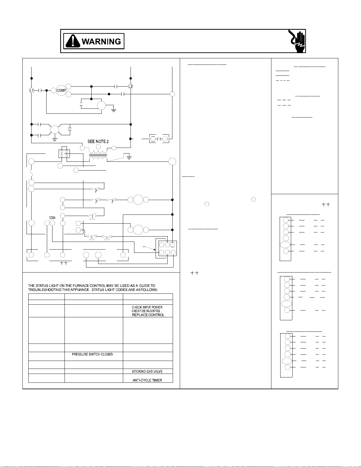
L1
C
T1
T1
HEAT
EM
PCB
COOL
F
4
5
IIC
9
7
GR
TO THERMOSTAT
TERMINAL BLOCK
STA TU S LIGHT
ON
OFF
1 BLINK
2 BLINKS
3 BLINKS
4 BLINKS
5 BLINKS
6 BLINKS
CPG036(048)*3D THREE PHASE 230V/60HZ DIRECT DRIVE
SUPPLY VOLTAGE
208-240/3/60
T2
T3
TB1
FS
3
6
8
10
W Y2
INSTALLER/SERVICEMAN
T2
FC
FC
12
11
NORMAL OP ERA TION
INTERNAL CONTROL
IGNITION FAILURE
OPEN AUX. LIMIT
PRESSURE SWITCH
WITHOUT INDUCER ON
OPEN LIM IT SWITCH
FA LSE FL AM E SEN SED
OUTPUT DELAY
CM
2
IGN
LS
ALS
PS
LPS
HPS
Y1
EQUIP . STA TU S
NO POWER OR
FAULT
OR
OPEN R OLLOUT
SWITCH
OR
SWITCH
OPEN
COMPRESSO R
FS
HIGH VOLTAGE!
DISCONNECT ALL POWER BEFORE SERVICING OR INSTALLING THIS
UNIT. MULTIPLE POWER SOURCES MAY BE PRESENT. FAILURE TO
DO SO MAY CAUSE PROPERTY DAMAGE, PERSONAL INJURY OR DEATH.
OMPONENT LEGEND
L2 L3
C
T3
C
PCB
VM
13
LI
DI
TR
IIC
RS
GV
C
NOTE
4
C
TB1
GAS FLOW
GAS PRES SURE
GAS VALVE
FLAM E SENSOR
FLAME ROLLOUT
BAD SWITC H
AUX. LIMIT OPEN
PRESSURE SWI TCH
PRESSURE SWI TCH
MAIN LIMIT OPEN
BAD SWITC H
3 MIN. COMP.
PLF
CHECK
-
CHECK
CHECK
56
321
C
ALS
AUXILIARY LIMIT SWITCH
COMP
COMPRESSOR
CM CONDENSER MOTOR
C
CONTACTOR
EVAPOR ATOR MOTOR
EM
F
L3
N
1. REPLACEMENT WIRE MUST BE THE SAME
SIZE AND TYPE OF INSULATION AS ORIGINAL.
(USE COPPER CONDUC TOR ONLY).
2. FOR 208 VOLT TRANSFORMER OPERATION
MOVE BLACK WIRE FROM TERMINAL 3 TO
TERMINAL 2 ON TRANSFORMER.
3. FOR DIFFERENT THAN FACTORY SPEED TAP.
CHANGE COOLING SPEED AT COOL
TERMINAL. CHANGE HEATING SPEED AT
HEAT TERMINAL ON CONTROL BOARD
4
4. ACCESSORY ECONOMIZER PLUG ADJACENT
TO BLOWER HOUSING IN RETURN AIR
COMPARTMEN T. REMOVE MALE PLUG AND
ATTACH FEMA LE PLUG TO ECONOMIZER
ACCESSORY.
5. USE COPPER CONDUCTORS ONLY.
6. PURPLE WIRE CONNECTS TO TRANSFORMER
(PIN 1).
7. SPEED TAP TERM INATIONS SHOWN ON
DIAGRAM ARE RE PRESENTATIVE, BUT ACTUAL
FACTORY SETTING MAY BE DIFFERENT BASED
ON HEATING VALUE AND CAPACITY OF UNIT.
8. TO RUN DIFFER ENT SPEED FOR HEATING AND
COOLING, DISCONNECT GEEEN JUMPER FROM
"COOL" TERMINAL AND REPLACE WITH
APPROPRIATE SPEED TAP. THEN PLACE
DISCONNECTED END OF JUMPER ON
"UNUSED" TERMINAL LEFT OPEN BY MOVING
THE S PEED TAP.
9. FOR LOW STAGE OPERATION ONLY, REMOVE
WHITE JUMPER. FOR 2 STAGE OPERATION,
REMOVE JUMPER AN D CONNECT W2 TO W1
ON THERMOSTAT.
SEE UNIT RATING PLA TE FOR TYPE AND SI ZE OF
OVERCURRENT PROTECTION.
FUS E
FC
FAN CAPACITOR
FS
FLAME SENSOR
EQUIPMENT GROUND
GND
GV
GAS VALVE
HPS HIGH PR E S S U RE SWITCH
IIC
INTEGRATED IGNITION CONTROL
IGNITOR
IGN
LS LIMIT SWITCH
LPS LOW PRES S URE SWITCH
PLF
FEMALE PLUG/CONNECTOR
PRESSURE SWITCH
PS
RS
TB1
TR
VM
VMR
BC
OTES
SPEED MOTOR
3
RD - LOW SPEED
BL - MED. SPEED
BK - HIGH SPEED
ROLLOUT SWITCH
TERMINAL BLOCK (24V SIGNAL)
TRANSFORMER
VENT MOTOR
VENT MOTOR RELAY
BLOWER CAPACI TO R
USE NEC CLASS 2 WIRE.
208-240/3/60 0140L00507 REV A
FACTORY WIRING
LINE VOLTAGE
LOW VOLTAGE
OPTIONAL
HIGH VOLTAGE
FIELD WIRING
HIGH VOLTAGE
LOW VOLTAGE
W
BK BLACK
BL BLUE
BR BROWN
GR GREEN
OR ORANGE
PK PINK
PU PURPLE
RD RED
WH WHIT E
YL YELLOW
BL/PK BLUE WITH PINK STRIP
YL/PK YELLOW WITH PINK STRIP
IRE CODE
THERMOSTAT
FIELD WIRING
NO
ECONOMIZER
W
G
R
Y1
Y/Y2
C
TB1
WITH
ECONOMIZER OPTION
W
G
R
Y1
Y/Y2
C
TB1
2
STAGE COOLING
W
G
R
Y1
Y/Y2
C
TB1
WH
GR
RD
YL
BL
WH
GR
RD
YL
BL
WH
GR
RD
YL
PK
BL
W
G
R
Y
C
STAT
W
G
R
Y
C
STAT
W
G
R
Y1
Y2
C
STAT
Wiring is subject to change. Always refer to the wiring diagram on the unit for the most up-to-date wiring.
47
Page 48

CPG036(48)0904B(7B)/CPG060*4B(7B)/CPG072*4B(7B) THREE PHASE 460V/575V/60HZ BELT DRIVE
A
HIGH VOLTAGE!
DISCONNECT ALL POWER BEFORE SERVICING OR INSTALLING THIS
UNIT. MULTIPLE POWER SOURCES MAY BE PRESENT. FAILURE TO
DO SO MAY CAUSE PROPERTY DAMAGE, PERSONAL INJURY OR DEATH.
YL
EM
BR
COMP
CM
BC
PU
BK
GR
LS
RD
RD
BL
RD
BL
RD
BK
PU
BK
BK
1
460
575
BK
BK
TR
24V
PK
T1 T2
L1 L2
C
OR
OR
23
C
BL
BL
BK
460/575
GR
TR
240
OR
OR
T3
L3
3
1
RD
RD
YL
POWER SUPPLY
460/3/60
575/3/60
SEE NOTE 4
BK
2
BL
VMR
WH
GND
BK
RD
OR
T1
T2
T3
OR
ALS
PU
PS
PU
YL
YL
NOTE 2
PLF
OR
RS
63
5412
YL
PU
W. R .
GAS VALVE
WH
PU
GV
(ALT.) HONEYWELL
GAS VALVE
MV
GV
MV
BL
BL
BL
BR
VM
FS
IGN
BK
L1
C
RD
L2
OR
L3
TB1
S1
S2
BR
SMOKE/FIRE
DETECTOR
REPLACES JUMPER
WIRE
OR
BL
YL
PU
GR
BL
YL
BL
RD
WH
BR
W2
RD
BL
PU
YL
GR
RD
RD
1
3265
YL
RD
RD
BL
BL
BL
BL
GYY1CRW
GR
10
7
4
8
11
12
9
WH
YL
YL
FS
DI
L1
UNUSED
L2
HE
TCOOL
RD
WH
BR
SEE
SEE
NOTE 3
NOTE 3
GR
IIC
YL/PK
GR
BK
LPS
WH
SEE
RD
OR
NOTE 5
HPS
BL/PK
BK
BR
FC
RD
460-575/3/60 0140L00870 REV A
Wiring is subject to change. Always refer to the wiring diagram on the unit for the most up-to-date wiring.
48
Page 49

CPG036(48)0904B(7B)/CPG060*4B(7B)/CPG072*4B(7B) THREE PHASE 460V/575V/60HZ BELT DRIVE
HIGH VOLTAGE!
DISCONNECT ALL POWER BEFORE SERVICING OR INSTALLING THIS
UNIT. MULTIPLE POWER SOURCES MAY BE PRESENT. FAILURE TO
DO SO MAY CAUSE PROPERTY DAMAGE, PERSONAL INJURY OR DEATH.
L1
C
BC
NOTE 3
F
4
5
IIC
9
R
STATUS LIGHT
ON
OFF
1 BLINK
2 BLINKS
3 BLINKS
4 BLINKS
5 BLINKS
6 BLINKS
T1
EM
BK
H C
SUPPLY VOLTAGE
T2
T1
T3
RD
FS
D1
460-575/3/60
FC
VMR
1
OR
1
LS
C
BC
L2 L3
NOTE 3
IIC
T2
CM
BC
VM
3
C
T3
BC
TR
IGN
FS
VMR
COMPONENT LEGEND
AUXILIARY LIMIT SWITCH
ALS
BLOWER CONTACTOR
BC
COMPRESSOR
COMP
CONDENSER MOTORCM
C
CONTACTOR
EM
EVAPORATOR MOTOR
F
FUSE
FC
FA N CA PACITOR
FS
FLAME SENSOR
GND
EQUIPMENT GROUND
GV
GAS VALVE
HIGH PRESSURE SWITCH
HPS
IBR INDOOR BLOWER RELAY
IIC
INTEGRATED IGNITION CONTROL
IGN
IGNITOR
LPS LOW PRESSURE SWITCH
LIMIT SWITCHLS
PLF
FEMALE PLUG/CONNECTOR
PRESSURE SWITCH
PS
RS
ROLLOUT SWITCH
TB1
TERMINAL BLOCK (24V SIGNAL)
TRANSFORM ERTR
VM
VENT MOTOR
VMR
VENT MOTOR RELAY
FACTORY WIRING
LINE VOLTAGE
LOW VOLTAGE
OPTIONAL HIGH
VOLTAG E
FIELD WIRING
HIGH VOLT AGE
LOW VOLTAGE
WIRE CODE
BK BLACK
BL BLUE
BR BROWN
GR GREEN
OR ORANGE
PK PINK
PU PURPLE
RD RED
WH WHITE
YL YELLOW
BL/PK BLUE WITH PINK STR IP
YL/PK YELLOW WITH PINK STRIP
THERMOSTAT
FIELD WIRING
ALS
3
6
8
7
10
12
11
LPS
Y1
W
G
RS
PS
HPS
Y
Y2
GV
C
NOTE 2
C
PLF
6
3
INST ALLER /SERVICEMAN
EQUI P. STATU S
NORMAL OPERATION
NO POWER OR
INTERNAL CONTROL
IGNITION FAILURE
OPE N RO L L OUT
SWITCH
OPEN AUX. LIMIT
SWITCH
PRESSURE SWITCH
OPEN
WITHOUT INDUCER ON
OPEN LIMIT SWITC H
FALSE FLAM E SEN SED
COMPRESSOR
OUTPUT DELAY
CHECK
-
GAS FLOW
GAS PRESSU RE
GAS VALVE
FLAME SENSOR
FLAME ROLLOUT
BAD SWITCH
AUX. LIMIT OPEN
CHECK
PRESSURE SWITCH
CHECK
PRESSURE SWITCH
MAIN L IM IT OPEN
BAD SWITCH
3 MIN. COMP.
NOTES
1. REPLACEMEN T WIRE M UST BE THE SAME
SIZE AND TYPE OF INSULATION AS ORIGINAL.
(USE COPPER CONDUCTOR ONLY).
2. ACCESSORY ECONOMIZER PLUG ADJACENT
TO BLOWER HOUSING IN RETURN AIR
COMPARTMENT. REMOVE MALE PLUG AND
ATTACH FEMALE PLUG TO THE ECONOMIZER
ACCESSORY.
3. L1 AND L2 ON IIC CONTROL IS 24V INPUT.
4. USE COPPER CONDUCTORS ONLY.
5
4
5. FOR LO W STAGE OPERATION ONLY, REMOVE
2
1
WHITE JUMPER. FOR 2 STAGE OPERATION,
REMOVE JUMPER A ND CONNECT W2 TO W2
ON THERMOSTAT.
USE NEC CLASS 2 WIRE.
SEE UNIT RA TING PLATE FOR TYPE AND
SIZE OF OVE R CURRENT PROTE CT I ON .
460-575/3/60 0140L00870 REV A
NO ECONOMIZER
W
G
R
WH
GR
RD
Y1
Y/Y2
C
TB1
YL
BL
STAT
WITH ECONOMIZER OPTION
W
G
R
Y1
WH
GR
RD
YL
Y/Y2
C
TB1
BL
STAT
2 STAGE COOLING
W
G
R
Y1
Y/Y2
C
TB1
WH
GR
RD
YL
PK
BL
STAT
W
G
R
Y
C
W
G
R
Y
C
W
G
R
Y1
Y2
C
Wiring is subject to change. Always refer to the wiring diagram on the unit for the most up-to-date wiring.
49
Page 50

CPG036(048)0903B/CPG060*3B/CPG072*3B THREE PHASE 208-230V/60HZ BEL T DRIVE
HIGH VOLTAGE!
DISCONNECT ALL POWER BEFORE SERVICING OR INSTALLING THIS
UNIT. MULTIPLE POWER SOURCES MAY BE PRESENT. FAILURE TO
DO SO MAY CAUSE PROPERTY DAMAGE, PERSONAL INJURY OR DEATH.
YL
COMP
BL
RD
BK
PU
BK
BL
T1 T2
L1 L2
C
RD
GND
T3
YL
L3
WH
BK
BK
RD
1
23
C
208
240
TR
TB1
24V
BL
S1
S2
BR
BL
SMOKE/FIRE DETECTOR
REPLACES JUMPER
WIRE
PK
RD
RD
EM
PU
BR
BK
BK
CM
BK
LS
GR
BC
OR
BK
RD
T1
T2T3
BK
L1
C
RD
L2
OR
L3
OR
BL
ALS
RD
GW2
RD
YL
RD
BL
BL
BL
BL
SEE NOTE 6
RD
GR
RD
PU
OR
PS
PU
RS
PU
W. R.
GAS VALVE
GV
VM
NOTE 2
PLF
PU
BR
YL
YL
YL
(ALT . ) H O NE Y W E L L
GAS VALVE
BL
BL
GR
YL
63
5412
BL
PU
MV
YL BL
RD
GV
MV
TO THERMOSTAT
FS
IGN
RD
OR
BL
PU
YL
WH
GR
BR
RCY Y1
W
RD
WH
WH
BR
SEE
NOTE 3
GR
OR
BK
GR
OR
3
1
VMR
POWER SUPPLY
208-240/3/60
SEE NOTE 4
BK
2
BL
WH
IIC
YL
YL
YL
RD
YL/PK
GR
LPS
BL/PK
HPS
BK
BR
FC
RD
208-240/3/60 0140L00981 REV A
Wiring is subject to change. Always refer to the wiring diagram on the unit for the most up-to-date wiring.
50
Page 51

CPG036(048)0903B/CPG060*3B/CPG072*3B THREE PHASE 208-230V/60HZ BEL T DRIVE
HIGH VOLTAGE!
DISCONNECT ALL POWER BEFORE SERVICING OR INSTALLING THIS
UNIT. MULTIPLE POWER SOURCES MAY BE PRESENT. FAILURE TO
DO SO MAY CAUSE PROPERTY DAMAGE, PERSONAL INJURY OR DEATH.
OMPONENT LEGEND
L1
C
BC
NOTE 3
F
4
5
IIC
7
9
G
R
TO THERMOSTAT
STATUS LIGHT
ON
OFF
1 BLINK
2 BLINKS
3 BLINKS
4 BLINKS
5 BLINKS
6 BLINKS
T1
T1
EM
FS
H C
D1
3
6
8
10
12
11
Y1
W
W2
INSTALLER/SERVICEMAN
WITHOUT INDUCER ON
FALSE FLAME SENSED
SUPPLY VO LTAGE
208-240/3/60
T2
T3
FC
1
LS
ALS
PS
LPS
Y
Y2
EQUIP. STATUS
NORMAL OPERATION
NO POWER OR
INTERNAL CONTROL
IGNITION FAILURE
OPEN ROLLOUT
SWITCH
OPEN AUX. LIMIT
SWITCH
PRESSURE SWITCH
OPEN
OPEN LIMIT SWITCH
COMPRESSOR
OUTPUT DELAY
T2
T3
CM
BC
BC
31 VM
3
TR
IGN
FS
VMR
RS
HPS
C
L2 L3
C
C
VMR
NOTE 3
BC
GV
C
NOTE 2
PLF
CHECK
-
GAS FLOW
GAS PRESSURE
GAS VALVE
FLAME SENSOR
FLAME ROLLOUT
BAD SWITCH
AUX. LIMIT OPEN
CHECK
PRESSURE SWITCH
CHECK
PRESSURE SWITCH
MAIN LIM IT OPEN
BAD SWITCH
3 MIN. COMP.
IIC
6
5
3
2
C
AUXILIARY LIMIT SWITCH
ALS
BLOWER CONTACTOR
BC
COMP
COMPRESSOR
CONDENSER MOTORCM
CONTACTOR
C
EVAPOR AT OR MOTOR
EM
F
FUSE
FC
FAN CAPACITOR
FLAME SENSOR
FS
EQUIPMEN T GROUND
GND
GAS VALVE
GV
HPS HIGH PRESSURE SWITCH
IBR INDOOR BLOWER RELAY
INTEGRATED IG NI TION C ON TROL
IIC
IGNITOR
IGN
LPS L OW PRESSU RE SWITCH
LIMIT SWIT CHLS
FEMALE PLUG/CONNECTOR
PLF
PRESSURE SWITCH
PS
ROLLOUT SWITCH
RS
TB1
TERMINAL BLOCK (24V SIGNAL)
TRANSFORMERTR
VENT MOTOR
VM
VMR
VENT MOTOR RELAY
NOTES
1. REPLACEMENT WIRE MUST BE THE SAME
SIZE AND TYPE OF INSULATION AS ORIGINAL.
(USE COPPER CONDUCTOR ONLY).
2. ACCESSO RY ECONOMIZER PLU G ADJ ACENT
TO BLOWER HOUSING IN RETURN AIR
COMPARTMENT. REMOVE MALE PLUG AND
ATTACH FEMALE PLUG TO THE E CONOMIZER
ACCESSORY.
3. L1 AND L2 ON IIC CONTROL IS 24V INPUT.
4. USE COPPER CONDUCTORS ONLY.
4
5. FOR 20 8 VOLT TR A NS F O RMER OPERATION,
1
MOVE BLACK WIRE FROM TERMINAL 3 TO
TERMINAL 2 ON TRANSFORMER.
6. FOR LOW STAG E O PERATION ONL Y , REMO VE
WHITE JUMPER. FOR 2 STAG E OPERATION,
REMOVE JUMPER AND CONNECT W2 TO W2
ON THERMOSTAT.
USE NEC CLASS 2 WIRE.
SEE UNIT RATING PLATE FOR TYPE AND SIZE OF OVER
CURRENT PROTECTION
208-240/3/60 0140L00981 REV A
FACTORY WIRING
LINE VOLTAGE
LOW VOLT AGE
OPTIONAL
HIGH VOLTAGE
LD WIRING
FIE
HIGH VOLTAGE
LOW VOLTAGE
WIRE
BK BLACK
BL BLUE
BR BROWN
GR GREEN
OR ORANGE
PK PINK
PU PURPLE
RD RED
WH WHITE
YL YELLOW
BL/PK BLUE WITH PINK STRIP
YL/PK YELLOW WITH PINK STRIP
CODE
THERMOSTAT
FIELD WIRING
NO ECONO
MIZER
W
G
R
Y1
Y/Y2
C
TB1
WI
TH ECONOMIZER OPTION
W
G
R
Y1
Y/Y2
C
TB1
W
G
RRD
Y1
Y/Y2
C
TB1
WH
GR
RD
YL
BL
WH
GR
RD
YL
BL
2 STAGE COOLING
WH
GR
YL
PK
BL
W
G
R
Y
C
STAT
W
G
R
Y
C
STAT
W
G
R
Y1
Y2
C
STAT
Wiring is subject to change. Always refer to the wiring diagram on the unit for the most up-to-date wiring.
51
Page 52

A
EM
BR
CPG036(048)0454B THREE PHASE 575V/60HZ BEL T DRIVE
HIGH VOLTAGE!
DISCONNECT ALL POWER BEFORE SERVICING OR INSTALLING THIS
UNIT. MULTIPLE POWER SOURCES MAY BE PRESENT. FAILURE TO
DO SO MAY CAUSE PROPERTY DAMAGE, PERSONAL INJURY OR DEATH.
YL
COMP
CM
BC
PU
GR
BK
LS
BL
BL
RD
RD
RD
RD
BK
PU
BK
BK
BK
BK
460 C
TR
575
24V
PK
T1 T2
L1 L2
C
OR
OR
BL
BL
BK
460/575
GR
240
OR
OR
TR
T3
L3
3
1
RD
RD
YL
POWER SUPPLY
460/3/60
575/3/60
SEE NOTE 4
2
VMR
WH
GND
BK
BL
BK
RD
OR
T1
T2
T3
OR
ALS
PU
PS
PU
RS
OR
PU
W. R.
GAS VALVE
GV
WH
YL
NOTE 2
PLF
(ALT.) HONEY WELL
GAS VALVE
PU
BL
BL
BL
YL
63
5412
YL
MV
GV
MV
BK
L1
C
RD
L2
OR
L3
BL
RD
RD
BL
PU
YL
GR
YL
YL
BL
PU
RD
BL
BL
YL
Y2
Y1
BL
C
WH
RD
RW1
GR
BL
BL
G
TB1
RD
1
3265
RD
DI
L2
S1
S2
BR
10
4
7
8
11
12
9
FS
L1
UNUSED
HE
TCOOL
SMOKE/FIRE
DETECTOR
REPLACES JUMPER
WIRE
OR
GR
YL
WH
RD
WH
BR
SEE
SEE
NOTE 3
NOTE 3
GR
GR
YL
IIC
YL/PK
LPS
BK
VM
FS
IGN
RD
OR
BL/PK
HPS
BK
BR
FC
RD
FC
460-575/3/60 0140L00871 REV A
Wiring is subject to change. Always refer to the wiring diagram on the unit for the most up-to-date wiring.
52
Page 53

CPG036(048)0454B THREE PHASE 575V/60HZ BELT DRIVE
HIGH VOLTAGE!
DISCONNECT ALL POWER BEFORE SERVICING OR INSTALLING THIS
UNIT. MULTIPLE POWER SOURCES MAY BE PRESENT. FAILURE TO
DO SO MAY CAUSE PROPERTY DAMAGE, PERSONAL INJURY OR DEATH.
L1
C
BC
NOTE 3
F
4
5
IIC
9
R
STATUS LIGHT
ON
OFF
1 BLINK
2 BLINKS
3 BLINKS
4 BLINKS
5 BLINKS
6 BLINKS
T1
EM
BK
H C
SUPPLY VOLTAGE
T2
T1
T3
RD
FS
D1
460-575/3/60
FC
VMR
3
OR
1
LS
C
BC
L2 L3
NOTE 3
IIC
T2
CM
BC
VM
3
C
T3
BC
TR
IGN
FS
VMR
COMPONENT LEGEND
AUXILIARY LIMIT SWITCH
ALS
BLOWER CONTACTOR
BC
COMPRESSOR
COMP
CONDENSER MOTORCM
C
CONTACTOR
EM
EVAPORATOR MOTOR
F
FUSE
FC
FA N CA PACITOR
FS
FLAME SENSOR
GND
EQUIPMENT GROUND
GV
GAS VALVE
HIGH PRESSURE SWITCH
HPS
IBR INDOOR BLOWER RELAY
IIC
INTEGRATED IGNITION CONTROL
IGN
IGNITOR
LPS LOW PRESSURE SWITCH
LIMIT SWITCHLS
PLF
FEMALE PLUG/CONNECTOR
PRESSURE SWITCH
PS
RS
ROLLOUT SWITCH
TB1
TERMINAL BLOCK (24V SIGNAL)
TRANSFORM ERTR
VM
VENT MOTOR
VMR
VENT MOTOR RELAY
FACTORY WIRING
LINE VOLTAGE
LOW VOLTAGE
OPTIONAL HIGH
VOLTAG E
FIELD WIRING
HIGH VOLTAGE
LOW VOLTAGE
WIRE CODE
BK BLACK
BL BLUE
BR BROWN
GR GREEN
OR ORANGE
PK PINK
PU PURPLE
RD RED
WH WHITE
YL YELLOW
BL/PK BLUE WITH PINK STR IP
YL/PK YELLOW WITH PINK STRIP
THERMOSTAT
FIELD WIRING
ALS
3
6
8
7
10
12
11
LPS
Y1
W
G
RS
PS
HPS
Y
Y2
GV
C
NOTE 2
C
PLF
6
3
INST ALLER /SERVICEMAN
EQUI P. STATU S
NORMAL OPERATION
NO POWER OR
INTERNAL CONTROL
IGNITION FAILURE
OPE N RO L L OUT
SWITCH
OPEN AUX. LIMIT
SWITCH
PRESSURE SWITCH
OPEN
WITHOUT INDUCER ON
OPEN LIMIT SWITC H
FALSE FLAM E SEN SED
COMPRESSOR
OUTPUT DELAY
CHECK
-
GAS FLOW
GAS PRESSURE
GAS VALVE
FLAME SENSOR
FLAME ROLLOUT
BAD SWITCH
AUX. LIMIT OPEN
CHECK
PRESSURE SWITCH
CHECK
PRESSURE SWITCH
MAIN L IM IT OPEN
BAD SWITCH
3 MIN. COMP.
NOTES
1. REPLACEMENT WIRE MUST BE THE SAME
SIZE AND TYPE OF INSULATION AS ORIGINAL.
(USE COPPER CONDUCTOR ONLY).
2. ACCESSORY ECONOMIZER PLUG ADJACENT
TO BLOWER HOUSING IN RETURN AIR
COMPARTMENT. REMOVE MALE PLUG AND
ATTACH FEMALE PLUG TO THE ECONOMIZER
ACCESSORY.
3. L1 AND L2 ON IIC CONTROL IS 24V INPUT.
4. USE COPPER CONDUCTORS ONLY.
5
4
2
1
USE NEC CLASS 2 WIRE.
SEE UNIT RA TING PLATE FOR TYPE AND
SIZE OF OVER CURRENT PROTECTION.
460-575/3/60 0140L00871 REV A
NO ECONOMIZER
W
G
R
WH
GR
RD
Y1
Y/Y2
C
TB1
YL
BL
STAT
WITH ECONOMIZER OPTION
W
G
R
Y1
WH
GR
RD
YL
Y/Y2
C
TB1
BL
STAT
2 STAGE COOLING
W
G
R
Y1
Y/Y2
C
TB1
WH
GR
RD
YL
PK
BL
STAT
W
G
R
Y
C
W
G
R
Y
C
W
G
R
Y1
Y2
C
Wiring is subject to change. Always refer to the wiring diagram on the unit for the most up-to-date wiring.
53
Page 54

EM
CPG036(048)0453B THREE PHASE 240V/60HZ BEL T DRIVE
HIGH VOLTAGE!
DISCONNECT ALL POWER BEFORE SERVICING OR INSTALLING THIS
UNIT. MULTIPLE POWER SOURCES MAY BE PRESENT. FAILURE TO
DO SO MAY CAUSE PROPERTY DAMAGE, PERSONAL INJURY OR DEATH.
YL
RD
BK
PU
BK
COMP
BL
BL
PU
BR
BK
BK
BK
CM
BK
LS
RD
GR
BC
RD
1
C
PK
T1 T2
L1 L2
C
BK
RD
23
208
240
TR
24V
BL
BL
OR
RD
BK
GR
T3
L3
RD
YL
3
2
1
VMR
WH
GND
POWER SUPPLY
208-240/3/60
SEE NOTE 4
BK
BL
BK
RD
OR
ALS
PU
OR
PS
PU
RS
PU
W. R.
GAS VALVE
NOTE 2
PLF
PU
YL
YL
(ALT.) HON EY WELL
GAS VALVE
GV
BL
WH
BL
L1
BK
C
T2T3 T1
RD
L2
OR
L3
OR
BL
TB1
S1
S2
BR
SMOKE/FIRE DETECTOR
REPLACES JUMPER
WIRE
OR
IIC
RD
RD
RD
BL
PU
YL
WH
GR
YL
RD
BL
BL
BL
BL
GR
YL
63
5412
BL
PU
YL
MV
YL BL
RD
GV
MV
Y1
W1
RCY2
G
GR
YL
YL
WH
RD
RD
WH
BR
SEE
NOTE 3
GR
GR
YL
YL/PK
LPS
VM
FS
IGN
BK
RD
OR
BR
BL/PK
FC
HPS
RD
FC
208-240/3/60 0140L00979 REV A
Wiring is subject to change. Always refer to the wiring diagram on the unit for the most up-to-date wiring.
54
Page 55
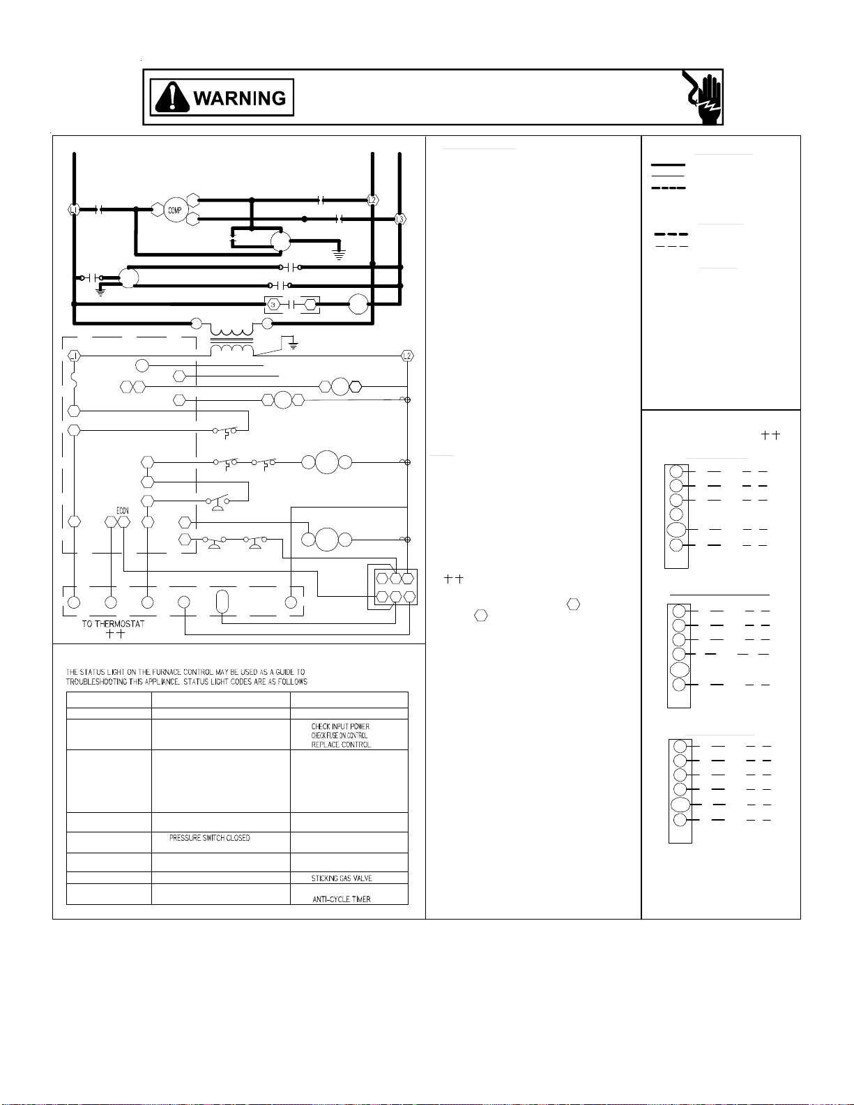
L1
C
BC
NOTE 3
F
4
5
9
R
STATUS LIGHT
1 BLINK
2 BLIN KS
3 BLIN KS
4 BLINKS
5 BLINKS
6 BLINKS
IIC
OFF
CPG036(048)0453B THREE PHASE 240V/60HZ BELT DRIVE
HIGH VOLTAGE!
DISCONNECT ALL POWER BEFORE SERVICING OR INSTALLING THIS
UNIT. MULTIPLE POWER SOURCES MAY BE PRESENT. FAILURE TO
DO SO MAY CAUSE PROPERTY DAMAGE, PERSONAL INJURY OR DEATH.
OMPONENT LEGEND
SUPPLY VOL TAG E
L2 L3
208-240/3/60
T1
T2
T1
T3
T2
FC
CM
C
T3
C
BC
TR
BC
VMR
VM
1
3
NOTE 3
IGN
FS
BC
IIC
EM
H C
1
FS
D1
LS
ALS
3
6
PS
VMR
RS
GV
8
7
10
12
11
LPS
W Y1
G
HPS
Y
Y2
C
NOTE 2
C
PLF
6
5
3
2
INSTALLER/SERVICEMAN
ON
EQUIP. STATUS
NORMAL OPERATION
NO POWER OR
INTER NAL CON TR OL
IGNITI ON FAILURE
OPEN ROLLOUT
SWITCH
OPEN AUX. LIMIT
SWITCH
PRESSURE SWITCH
OPEN
WITHOUT INDUCER ON
OPEN LIMIT SWITCH
FALSE FLAME SENSED
COMPRESSOR
OUTPUT DELAY
CHECK
-
GAS FLOW
GAS PRESSURE
GAS VALVE
FLAME SENSOR
FLAME ROLLOUT
BAD SWI TCH
AUX. LIMIT OPEN
CHECK
PRESS URE SWI TC H
CHECK
PRESS URE SWI TC H
MAIN LIMIT OPEN
BAD SWI TCH
3 MIN. COMP.
C
AUXILIARY LIMIT SWITCH
ALS
BLOWER CONTACTOR
BC
COMPRESSOR
COMP
CONDENSER MOTORCM
CONTACTOR
C
EVAP O R AT O R M OT O R
EM
FFUSE
FC
FAN CAPACITOR
FS
FLAME SENSOR
GND
EQUIPMENT GROUND
GV
GAS VALVE
HPS HIGH PRESSURE SWITCH
IBR INDOOR BLOWER RELAY
INTEGRATED IGNITION CONTROL
IIC
IGN
IGNITOR
LPS LOW PRE S SURE SWITCH
LIMIT SWITCHLS
FEMALE PLUG/CONNECTOR
PLF
PS
PRESSURE SWITCH
ROLLO U T SWITCH
RS
TERMINAL BLOCK (24V SIGNAL)
TB1
TRANSFORMERTR
VM
VENT MOTOR
VMR
VENT M OT O R REL A Y
NOTES
1. REPLAC EM ENT WIRE MUS T BE THE S A ME
SIZE AND TYPE OF INSULATION AS ORIGINAL.
(USE COPPER CONDUCTOR ONLY).
2. ACCESSORY ECONOMIZER PLUG ADJACENT
TO BLOWER HOUSING IN RETURN AIR
COMPARTMENT. REMOVE MALE PLUG AND
ATTACH FEMALE PLUG TO THE ECONOMIZER
ACCESSORY.
3. L1 AND L2 ON IIC CONTROL IS 24V INPU T.
4. USE COPPER CONDUCTORS ONLY.
4
5. FOR 208 VOLT TRANSFORMER O PERAT ION,
1
MOVE BLACK WIRE FROM TERMINAL 3 TO
USE NEC CLASS 2 WIRE.
TERMINAL 2 ON TRANSFORMER.
SEE UNIT RATING PLATE FOR TYPE AN D S I ZE OF OVER
CURRENT PROTECTION
208-240/3/60 0140L00979 REV A
FACTORY WIRING
LINE VOLTAGE
LOW VOLTAGE
OPTIONAL
HIGH VOLTAGE
WIRING
FIELD
HIGH VOLTAGE
LOW VOLTAGE
IRECODE
BK BLACK
BL BLUE
BR BROWN
GR GREEN
OR ORANGE
PK PINK
PU PURPLE
RD RED
WH WHITE
YL YELLOW
BL/PK BLUE WITH PINK STRIP
YL/PK YELLOW WITH PINK STRIP
W
THERMOSTAT
FIELD WIRING
NO ECONO
MIZER
W
G
R
Y1
Y/Y2
C
TB1
WITH ECO NOMIZE
W
G
R
Y1
Y/Y2
C
TB1
W
G
RRD
Y1
Y/Y2
C
TB1
AGE COOLING
2 ST
WH
GR
RD
YL
BL
R OPT ION
WH
GR
RD
YL
BL
WH
GR
YL
PK
BL
W
G
R
Y
C
STAT
W
G
R
Y
C
STAT
W
G
R
Y1
Y2
C
STAT
Wiring is subject to change. Always refer to the wiring diagram on the unit for the most up-to-date wiring.
55
Page 56

Goodman Manufacturing Company, L.P .
5151 Felipe, Suite 500, Houston, TX 77056
www.goodmanmfg.com www.amana-hac.com
© 2009-2010 Goodman Manufacturing Company, L.P.
56
 Loading...