

Page 1

I
NSTALLATION INSTRUCTIONS
L
IGHT
P
ACKAGED
C
OMMERCIAL
H
EATING
S
ELF
& C
-C
ONTAINED
OOLING
F
OR
U
NIT
15 & 20 T
®
C
US
ON
CPC
RECOGNIZE THIS SYMBOL AS A SAFETY PRECAUTION.
ATTENTION INSTALLING PERSONNEL
Prior to installation, thoroughly familiarize yourself with this Installation Manual. Observe all safety warnings.
During installation or repair, caution is to be observed.
It is your responsibility to install the product safely and to educate the customer on its safe use.
All information contained herein is subject to change without notice.
These installation instructions cover the outdoor
installation of single package electric heating and
cooling units. See the Specification Sheet applicable
to your model for information regarding accessories.
IO-367B
7/10
5151 San Felipe, Suite 500 ◊ Houston, TX 77056
www.goodmanmfg.com www.amana-hac.com
NOTE: Please contact your distributor or
our website for the applicable
Specification Sheet referred to in
this manual.
© 2010 Goodman Manufacturing Company, L.P .
Page 2
Index
REPLACEMENT PARTS
Replacement Parts ........................................................2
Safety Instructions ........................................................2
General Information ......................................................3
Unit Location ................................................................. 4
Clearances .....................................................................6
Roof Curb Post-Installation Checks ............................ 6
Roof Top Duct Connections ......................................... 6
Rigging Details ..............................................................7
Electrical Wiring ............................................................8
Circulating Air and Filters........................................... 10
Venting ......................................................................... 10
Condensate Drain Connection ...................................10
Startup, Adjustment s, and Checks ............................10
Air flow Adjustments................................................... 13
Motor Sheave Adjustments ........................................ 14
ORDERING PARTS
When reporting shortages or damages, or ordering repair
parts, give the complete unit model and serial numbers
as stamped on the unit’s nameplate.
Replacement parts for this appliance are available
through your contractor or local distributor. For the
location of your nearest distributor, consult the white
business pages, the yellow page section of the local
telephone book or contact:
CONSUMER AFFAIRS
GOODMAN MANUFACTURING COMPANY, L.P.
7401 SECURITY WAY
HOUSTON, TEXAS 77040
877-254-4729
SAFETY INSTRUCTIONS
TO THE INSTALLER
Before installing this unit, please read this manual to
familiarize yourself on the specific items which must be
adhered to, including maximum external static pressure
to unit, air temperature rise, minimum or maximum CFM
and motor speed connections.
Maintenance ................................................................14
Service .........................................................................15
Appendix A Blower Performance Data ...................... 16
Belt Drive - Standard...................................................16
Belt Drive - High Static................................................17
Appendix B Electrical Data.........................................18
Appendix C Unit Dimensions ..................................... 19
WARN ING
T
HIS PRODUCT CONTAINS OR PRODUCES A CHEMICAL OR CHEMICALS
WHICH MAY CAUSE SERIOUS ILLNESS OR DEATH AND WHICH ARE
KNOWN TO THE STATE OF CALIFORNIA TO CAUSE CANCER, BIRTH
DEFECTS OR OTHER REPRODUCTIVE HARM
.
Keep this literature in a safe place for future reference.
CAUTION
S
HEET METAL PARTS, SCREWS, CLIPS AND SIMILAR ITEMS INHERENTLY
HAVE SHARP EDGES, AND IT IS NECESSARY THAT THE INSTALLER AND
SERVICE PERSONNEL EXERCISE CAUTION
.
WARN ING
DO
NOT CONNECT TO OR USE ANY DEVICE THAT IS NOT DESIGN
CERTIFIED BY GOODMAN FOR USE WITH THIS UNIT
PROPERTY DAMAGE, PERSONAL INJURY, REDUCED UNIT
PERFORMANCE AND/OR HAZARDOUS CONDITIONS MAY RESULT FROM
THE USE OF SUCH NON-APPROVED DEVICES
. S
ERIOUS
.
WARNING
O AVOID PROPERTY DAMAGE, PERSONAL INJURY OR DEATH, DO NOT USE
T
THIS UNIT IF ANY PART HAS BEEN UNDER WATER.
QUALIFIED SERVICE TECHNICIAN TO INSPECT THE FURNACE AND TO REPLACE
ANY PART OF THE CONTROL SYSTEM AND ANY G AS CONTROL HAVING BEEN
UNDER WATER.
I
MMEDIATELY CALL A
WARNING
HIGH VOLTAGE!
ISCONNECT ALL POWER BEFORE SERVICING OR
D
INSTALLING THIS UNIT
BE PRESENT
DAMAGE, PERSONAL INJURY OR DEATH
. F
2
. M
AILURE TO DO SO MAY CAUSE PROPERTY
ULTIPLE POWER SOURCES MAY
.
Page 3
WARNING
TO PREVENT THE RISK OF PROPERTY DAMAGE, PERSONAL INJURY, O R DEATH,
DO NOT STORE COMBUSTIBLE MATERIA LS OR USE GASOLINE OR OTHER
FLAMMABLE LIQUI DS OR VAPORS I N THE V ICINIT Y OF THI S APPL IANCE.
WARNING
HIGHVOLTAGE!
I
NSTALLATIONANDREPAIROFTHISUNITSHOULDBE
PERFORMED
MINIMUM)THEREQUIREMENTSOFAN
T
ECHNICIAN”ASSPECIFIEDBYTHEAIRCONDITIONING
H
EATING,ANDREFRIGERATIONINSTITUTE
TTEMPTINGTOINSTALLORREPAIRTHISUNITWITHOUT
A
SUCHBACKGROUNDMAYRESULTINPRODUCTDAMAGE
PERSONALINJURYORDEATH
ONLYBY
INDIVIDUALSMEETING(ATA
“E
NTRYLEVEL
(AHRI).
.
GENERAL INFORMA TION
WARNING
O PREVENT PROPERTY DAMAGE, PERSONAL INJURY OR DEATH, DUE TO FIRE,
T
EXPLOSIONS, SMOKE, SOOT, CONDENSATION, ELECTRIC SHOCK OR CARBON
MONOXIDE, THIS UNIT MUST BE PROPERLY INSTALLED, REPAIRED, OPERATED,
AND MAINTAINED.
This unit is approved for outdoor installation ONLY. To
assure that your unit operates safely and efficiently, it must
be installed, operated, and maintained in accordance with
these installation and operating instructions, all local building
codes and ordinances.
EPA REGULATIONS
IMPORTANT: THE UNITED STATES ENVIRONMENTAL PROTECTION
AGENCY (EPA) HAS ISSUED VARIOUS REGULATIONS REGARDING
INTRODUCTION AND DISPOSAL OF REFRIGERANTS IN THIS UNIT.
THE
FAILURE TO FOLLOW THESE REGULATIONS MAY HARM THE
ENVIRONMENT
. BECAUSE REGULATIONS MA Y VARY DUE TO P ASSAGE OF NEW
FINES
, WE SUGGEST A CERTIFIED TECHNICIAN PERFORM ANY WORK
LAWS
ON THIS UNIT. SHOULD YOU HAVE ANY QUESTIONS PLEASE
DONE
CONTAC T
AND CAN LEAD TO THE IMPOSITION OF SUBSTANTIAL
THE LOCAL OFFICE OF THE EPA.
NATIONAL CODES
This product is designed and manufactured to permit installation in accordance with National Codes. It is the installer’s
responsibility to install the product in accordance with National Codes and/or prevailing local codes and regulations.
The heating and cooling capacities of the unit should be
greater than or equal to the design heating and cooling loads
of the area to be conditioned. The loads should be calculated
by an approved method or in accordance with ASHRAE Guide
or Manual J - Load Calculations published by the Air Conditioning Contractors of America.
,
,
Obtain from:
American National Standards Institute
1430 Broadway
New York, NY 10018
System design and installation should also, where applicable,
follow information presented in accepted industry guides such
as the ASHRAE Handbooks. The manufacturer assumes no
responsibility for equipment installed in violation of any code
or regulation. The mechanical installation of the packaged
roof top units consists of making final connections between
the unit and building services; supply and return duct connections; and drain connections (if required). The internal
systems of the unit are completely factory-installed and tested
prior to shipment.
Units are generally installed on a steel roof mounting curb
assembly which has been shipped to the job site for installation on the roof structure prior to the arrival of the unit. The
model number shown on the unit’s identification plate identifies the various components of the unit such as refrigeration
tonnage, heating input and voltage.
Carefully inspect the unit for damage. Any bolts or screws
which may have loosened in transit must be re-tightened. In
the event of damage, the receiver should:
1. Make notation on delivery receipt of any visible
damage to shipment or container.
2. Notify carrier promptly and request an inspection.
3. In case of concealed damage, carrier should be
notified as soon as possible-preferably within 5 days.
4. File the claim with the following supporting documents:
a. Original Bill of Lading, certified copy, or indemnity
bond.
b. Original paid freight bill or indemnity in lieu thereof.
c. Original invoice or certified copy thereof, showing
trade and other discounts or reductions.
d. Copy of the inspection report issued by carrier
representative at the time damage is reported to the
carrier. The carrier is responsible for making prompt
inspection of damage and for a thorough
investigation of each claim. The distributor or
manufacturer will not accept claims from dealers for
transportation damage.
NOTE: When inspecting the unit for transportation damage,
remove all packaging materials. Recycle or dispose of the
packaging material according to local codes.
PRE-INSTALLATION CHECKS
Carefully read all instructions for the installation prior to installing unit. Ensure each step or procedure is understood
and any special considerations are taken into account before starting installation. Assemble all tools, hardware and
supplies needed to complete the installation. Some items may
need to be purchased locally.
3
Page 4
UNIT LOCA TION
WARN ING
TO
PREVENT POSSIBLE EQUIPMENT DAMAGE, PROPERTY DAMAGE
PERSONAL INJURY OR DEATH, THE FOLLOWING BULLET POINTS MUST
BE OBSERVED WHEN INSTALLING THE UNIT
IMPORTANT NOTE: Remove wood shipping rails prior to
installation of the unit. See important note under Roof Curb
Installation Only.
.
,
ALL INSTALLATIONS:
I
MPORTANT NOTE: Unit should be energized 24 hours prior
to compressor start up to ensure crankcase heater has
sufficiently warmed the compressors. Compressor damage may occur if this step is not followed.
NOTE: Appliance is shipped from factory for vertical duct
application.
Proper installation of the unit ensures trouble-free operation.
Improper installation can result in problems ranging from
noisy operation to property or equipment damages, dangerous conditions that could result in injury or personal property
damage and could void the warranty . Give this booklet to the
user and explain it’s provisions. The user should retain these
instructions for future reference.
• For proper operation and condensate drainage, the
unit must be mounted level.
• The flue outlet hood must be at least three feet above
any forced air inlet located within ten feet. The
economizer/manual fresh air intake/motorized fresh
air intake and combustion air inlet mounted on the
unit are not affected by this restriction.
• Do not locate the unit in an area where the outdoor
air (i.e. combustion air for the unit) will be frequently
contaminated by compounds containing chlorine or
fluorine. Common sources of such compounds include
swimming pool chemicals and chlorine bleaches, paint
stripper, adhesives, p aints, varnishes, sealers, waxes
(which are not yet dried) and solvents used during
construction and remodeling. V arious commercial and
industrial processes may also be sources of chlorine/
fluorine compounds.
• To avoid possible illness or death of the building
occupants, do NOT locate outside air intake device
(economizer, manual fresh air intake, motorized fresh
air intake) too close to an exhaust outlet, gas vent
termination, or plumbing vent outlet. For specific
distances required, consult local codes.
• Allow minimum clearances from the enclosure for fire
protection, proper operation, and service access (see
Unit Clearances). These clearances must be
permanently maintained.
• When the unit is heating, the temperature of the return
air entering the unit must be between 50°F and 100°F .
GROUND LEVEL INSTALLATIONS ONLY:
• When the unit is installed on the ground adjacent to
the building, a level concrete (or equal) base is
recommended. Prepare a base that is 3” larger than
the package unit footprint and a minimum of 3” thick.
• The base should also be located where no runoff of
water from higher ground can collect in the unit.
ROOF TOP INSTALLATIONS ONLY:
• T o avoid possible property damage or personal injury ,
the roof must have sufficient structural strength to carry
the weight of the unit(s) and snow or water loads as
required by local codes. Consult a structural engineer
to determine the weight capabilities of the roof.
• The unit may be installed directly on wood floors or
on Class A, Class B, or Class C roof covering material.
• To avoid possible personal injury, a safe, flat surface
for service personnel should be provided.
• As indicated on the unit’s data plate, a minimum
clearance of 36” to any combustible material is
required on the access side of the unit. All combustible
materials must be kept out of this area.
• This 36” clearance must also be maintained to insure
proper combustion air flow. The combustion air intake
must not be blocked for any reason, including
blockage by snow.
• Adequate clearances from the unit to any adjacent
public walkways, adjacent buildings, building openings
or openable windows must be maintained in
accordance with National Codes.
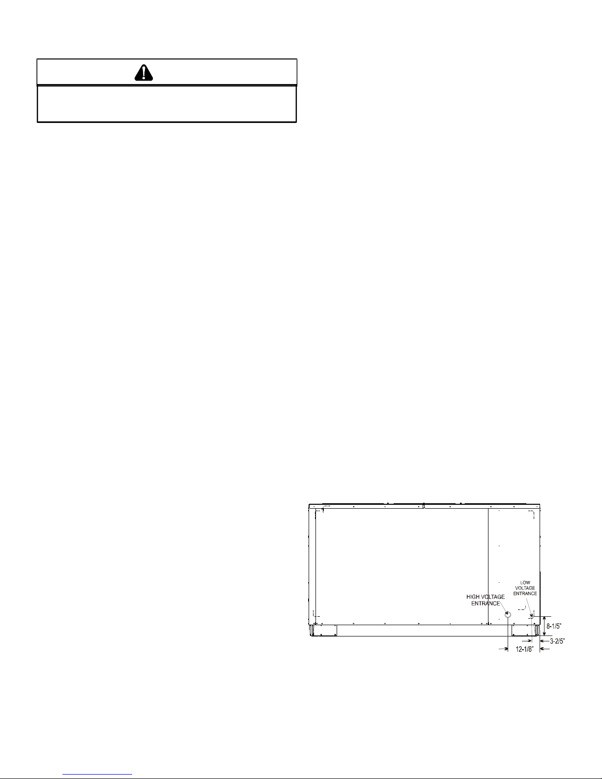
UNIT PRECAUTIONS
• Do not stand or walk on the unit.
• Except for holes in the wiring entrances (see Figure
below), do not drill holes anywhere in panels or in
the base frame of the unit. Unit access panels
provide structural support.
ELECTRICAL ENTRANCE LOCATIONS
• Do not remove any access panels until unit has been
installed on roof curb or field supplied structure.
• Do not roll unit across finished roof without prior
approval of owner or architect.
4
Page 5
• Do not skid or slide on any surface as this may
damage unit base. The unit must be stored on a
flat, level surface. Protect the condenser coil
because it is easily damaged.
ROOF CURB INSTALLATIONS ONLY:
3. Lift unit per the “Rigging Details” section of this manual,
observing all warnings and cautions. When unit is
lifted, boards and shipping brace will drop if screws
have been removed. T o avoid injury , ST AND CLEAR.
4. Dispose of the boards and brace appropriately.
Before installing this unit...
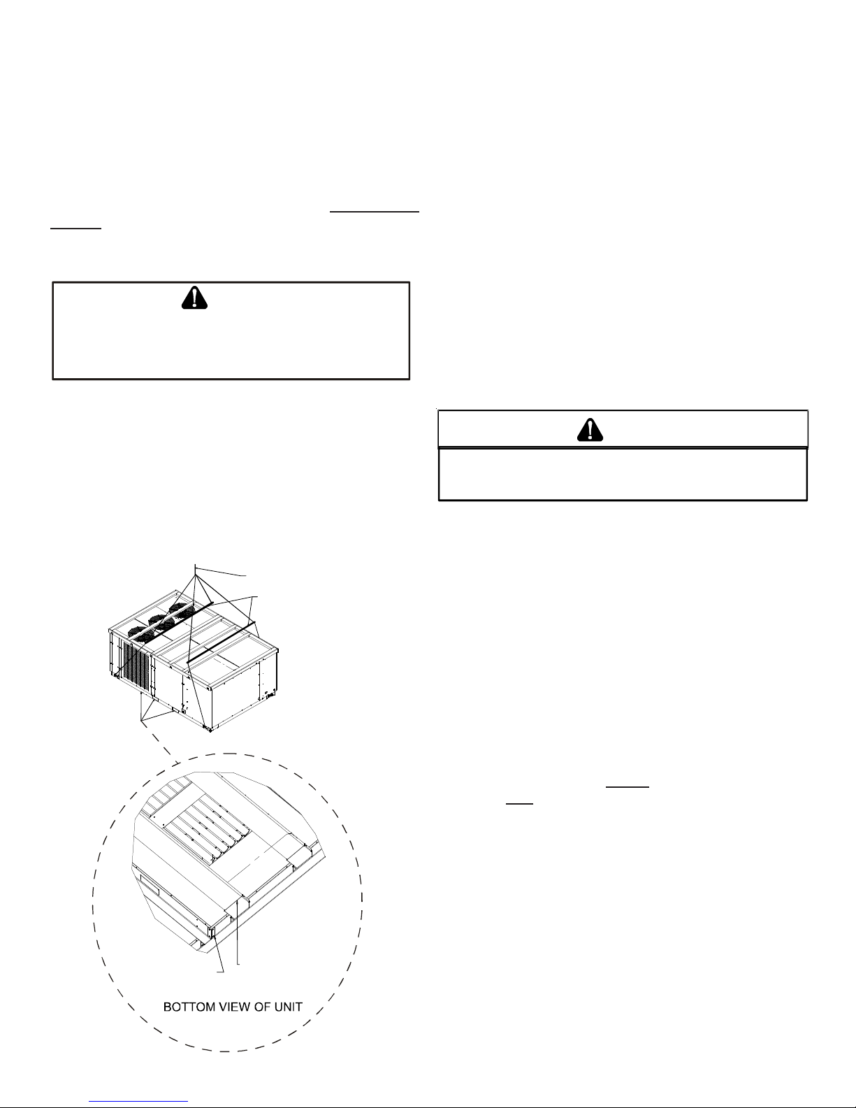
IMPORT ANT NOTE: This unit has been equipped with a shipping brace under the compressor section that MUST BE RE-
MOVED before installing the unit on a roof curb.
Please follow the instructions below to remove brace.
CAUTION
W
HENUNITISSUSPENDED,BOARDSANDSHIPPINGBRACEWILLDROPWHEN
SCREWSAREREMOVED
EMOVEFORKHOLEBRACKETS,BOARDSANDSHIPPINGBRACEFROMBOTTOM
R
UNITBEFOREPLACINGUNITONTOCURB
OF
.TO
PREVENTPERSONALINJURY
,STANDCLEAR.
.
1. Remove wooden struts and shipping brace per
installation instructions. The struts are located in the
fork holes and are used to protect the unit from
damage while lifting with forks. The shippping brace
is located underneath the unit (under compressors).
Also remove the fork hole brackets as shown in the
following figure.
2. Locate and remove the end brackets as shown below .
LIFT OVER APPROXIMATE
CENTER OF UN IT
SPREADER BARS
MUST BE USE D W ITH
LIFTING STRAPS THA T
ARE LESS THAN 16
FEET L ONG
Curb installations must comply with local codes and should
be done in accordance with the established guidelines of the
National Roofing Contractors Association.
Proper unit installation requires that the roof curb be firmly
and permanently attached to the roof structure. Check for
adequate fastening method prior to setting the unit on the
curb.
Full perimeter roof curbs are available from the factory and
are shipped unassembled. Field assembly, squaring, leveling and mounting on the roof structure are the responsibility
of the installing contractor . All required hardware necessary
for the assembly of the sheet metal curb is included in the
curb accessory.
WARN ING
TO
PREVENT POSSIBLE EQUIPMENT DAMAGE, PROPERTY DAMAGE
PERSONAL INJURY OR DEATH, THE FOLLOWING BULLET POINTS MUST
BE OBSERVED WHEN INSTALLING THE UNIT
.
,
• Sufficient structural support must be determined prior
to locating and mounting the curb and package unit.
• Ductwork must be constructed using industry
guidelines. The duct work must be placed into the
roof curb before mounting the package unit. Our full
perimeter curbs include duct connection frames to be
assembled with the curb. Cantilevered type curbs
are not available from the factory.
• Curb insulation, cant strips, flashing and general
roofing material are furnished by the contractor.
The curbs must be supported on parallel sides by roof members. The roof members must not penetrate supply and return duct opening areas as damage to the unit might occur.
REMOVE 2 BRACKE T S
ON EACH END TO
REMOVE
SHIPP I N G BR ACE
REMOVE 2 BRA C KETS
ON EACH END TO
REMOVE
WOODEN STRUTS
NOTE: The unit and curb accessories are designed to allow
vertical duct installation before unit placement. Duct
installation after unit placement is not recommended.
5
Page 6
CAUTION
ALL
CURBS LOOK SIMILAR
POSITIONING, CHECK JOB PLANS CAREFULLY AND VERIFY MARKINGS
ON CURB ASSEMBLY
SUPERSEDES INFORMATION SHOWN
. TO
AVOID INCORRECT CURB
. I
NSTRUCTIONS MAY VARY IN CURB STYLES AND
.
See the manual shipped with the roof curb for assembly and
installation instructions.
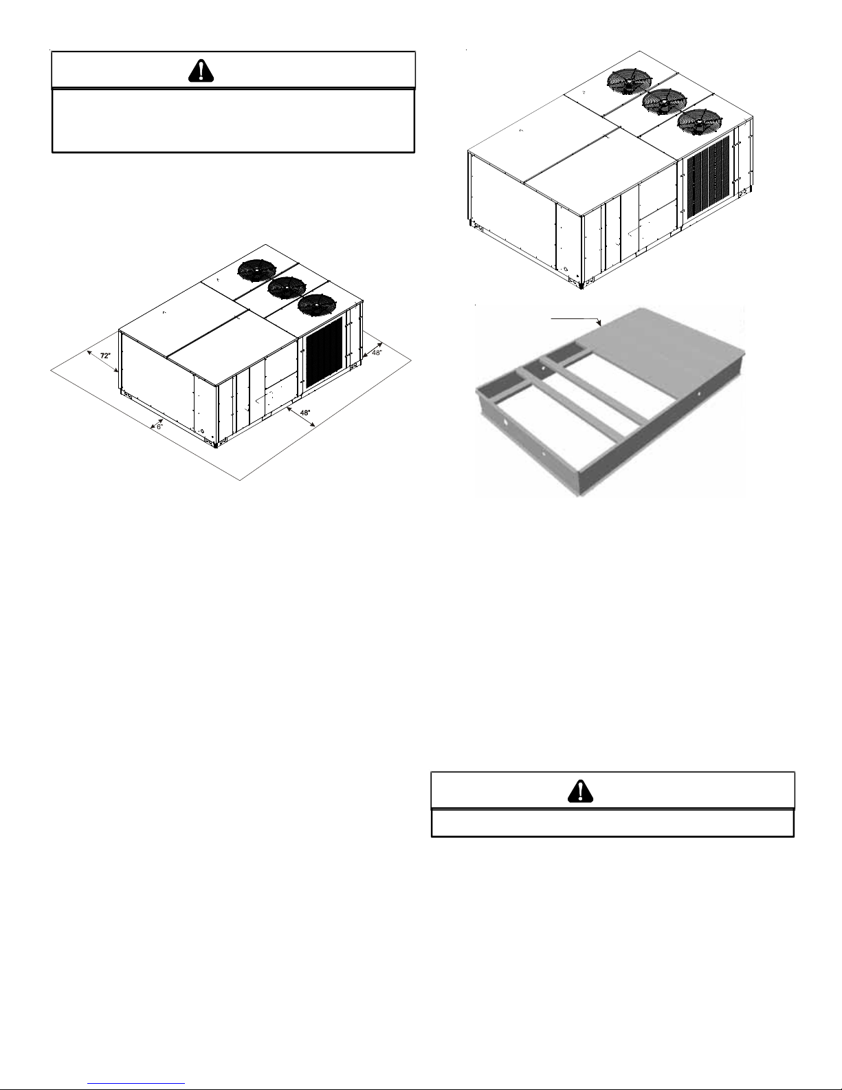
CLEARANCES
36”; minimum
roof overhang
Insulated
Panels
UNIT CLEARANCES
Adequate clearance around the unit should be kept for safety ,
service, maintenance, and proper unit operation. A total clearance of 75” on the main control panel side of the unit is recommended to facilitate possible fan shaft, coil, electric heat
and gas furnace removal. A clearance of 48” is recommended
on all other sides of the unit to facilitate possible compressor
removal, to allow service access and to insure proper ventilation and condenser airflow. The unit must not be installed
beneath any obstruction. The unit should be installed remote from all building exhausts to inhibit ingestion of exhaust
air into the unit fresh air intake.
Roof Curb Installation
ROOF CURB POST-INST ALLA TION
CHECKS
After installation, check the top of the curb, duct connection
frame and duct flanges to make sure gasket has been applied properly. Gasket should be firmly applied to the top of
the curb perimeter, duct flanges and any exposed duct connection frame. If gasket is loose, re-apply using strong
weather resistant adhesive.
PROTRUSION
Inspect curb to ensure that none of the utility services (electric) routed through the curb protrude above the curb.
CAUTION
IF
PROTRUSIONS EXIST, DO NO ATTEMPT TO SET UNIT ON CURB
.
ROOF TOP DUCT CONNECTIONS
Install all duct connections on the unit before placing the unit
on rooftop.
6
Page 7

RIGGING DET AILS
A
WARNING
O PREVENT PROPERTY DAMAGE, THE UNIT SHOULD REMAIN IN AN UPRIGHT
T
POSITION DURING ALL RIGGING AND MOVING OPERATIONS.
LIFTING AND MOVING WHEN A CRANE IS USED, PLACE THE UNIT IN AN
ADEQUATE CABLE SLING.
T
O FACILITATE
CAUTION
DO
NOT LIFT UNITS TWO AT A TIME
BEEN INCLUDED IN THE UNIT BASE FRAME
72”
TO PREVENT DAMAGE TO THE UNIT
. P
ROVISIONS FOR FORKS HAVE
. M
INIMUM FORK LENGTH IS
.
Provisions for forks have been included in the unit base frame.
No other fork locations are approved.
WARNING
O PREVENT POSSIBLE EQUIPMENT DAMAGE, PROPERTY DAMAGE, PERSONAL
T
INJURY OR DEATH, THE FOLLOWING BULLET POINTS MUST BE OBSERVED
WHEN INSTALLING THE UNIT.
• Unit must be lifted by the four lifting holes located at
the base frame corners.
• Lifting cables should be attached to the unit with
shackles.
• The distance between the crane hook and the top of
the unit must not be less than 60”.
• Two spreader bars must span over the unit to prevent
damage to the cabinet by the lift cables. Spreader
bars must be of sufficient length so that cables do not
come in contact with the unit during transport.
Remove wood struts mounted beneath unit base
frame before setting unit on roof curb. These struts
are intended to protect unit base frame from fork lift
damage. Removal is accomplished by extracting the
sheet metal retainers and pulling the struts through
the base of the unit. Refer to rigging label on the unit.
Important: If using bottom discharge with roof curb, ductwork should be attached to the curb prior to installing the
unit. Ductwork dimensions are shown in Roof Curb Installation Instructions.
CAUTION
W
HENUNITISSUSPENDED,BOARDSANDSHIPPINGBRACEWILLDROPWHEN
SCREWSAREREMOVED
R
EMOVEFORKHOLEBRACKETS,BOARDSANDSHIPPINGBRACEFROMBOTTOM
UNITBEFOREPLACINGUNITONTOCURB
OF
.TO
PREVENTPERSONALINJURY
,STANDCLEAR.
.
To assist in determining rigging requirements, unit weights
are shown as follows:
Y
COMPRESSOR 1
S
L
I
O
C
CG
COMPRESSOR 2
R
O
T
A
R
O
P
A
V
E
C
Refer to the Roof Curb Installation Instructions for proper curb
installation. Curbing must be installed in compliance with the
National Roofing Contractors Association Manual.
Lower unit carefully onto roof mounting curb. While rigging
unit, center of gravity will cause condenser end to be lower
than supply air end.
B
X
D
CORNER & CENTER OF GRAVITY LOCATIONS
7
Page 8

DATA
CPC Weights
(lbs)
CPC W eights
(lbs)
15 Tons 20 Tons
Corner Weight - A 580 655
Corner Weight - B 540 535
Corner Weight - C 475 510
Corner Weight - D 440 420
Unit Shipping Wei ght 2150 2235
Unit Operating Weight 2035 2120
WARN ING
HIGH VOLTAGE!
O AVOID PERSONAL INJURY OR DEATH DUE TO
T
ELECTRICAL SHOCK, DO NOT TAMPER WITH FACTORY
WIRING
. THE
OF THESE UNITS ARE FACTORY-INSTALLED AND HAVE
BEEN THOROUGHLY TESTED PRIOR TO SHIPMENT
ONTACT YOUR LOCAL REPRESENTATIVE IF
C
ASSISTANCE IS REQUIRED
INTERNAL POWER AND CONTROL WIRING
.
.
CAUTION
X (Inches)
Y (Inche s )
60" 58"
43" 40"
NOTE: These weights are without accessories installed.
CAUTION
TO
PREVENT SEVERE DAMAGE TO THE BOTTOM OF THE UNIT, DO NOT
FORK LIFT UNIT AFTER WOOD STRUTS HAVE BEEN REMOVED
.
Bring condenser end of unit into alignment with the curb. With
condenser end of the unit resting on curb member and using
curb as a fulcrum, lower opposite end of the unit until entire
unit is seated on the curb. When a rectangular cantilever
curb is used, care should be taken to center the unit. Check
for proper alignment and orientation of supply and return
openings with duct.
RIGGING REMOVAL
CAUTION
TO
PREVENT DAMAGE TO THE UNIT, DO NOT ALLOW CRANE HOOKS
AND SPREADER BARS TO REST ON THE ROOF OF THE UNIT
.
Remove spreader bars, lifting cables and other rigging equipment.
TO
PREVENT DAMAGE TO THE WIRING, PROTECT WIRING FROM
SHARP EDGES
LOCAL CODES AND ORDINANCES
REMOVABLE ACCESS PANELS
. F
OLLOW NATIONAL ELECTRICAL CODE AND ALL
.
. DO
NOT ROUTE WIRES THROUGH
CAUTION
C
ONDUIT AND FITTINGS MUST BE WEATHER-TIGHT TO PREVENT
WATER ENTRY INTO THE BUILDING
.
For unit protection, use a fuse or HACR circuit breaker that is
in excess of the circuit ampacity , but less than or equal to the
maximum overcurrent protection device. DO NOT EXCEED
THE MAXIMUM OVERCURRENT DEVICE SIZE SHOWN
ON UNIT DATA PLATE.
All line voltage connections must be made through weatherproof fittings. All exterior power supply and ground wiring
must be in approved weatherproof conduit.
The main power supply wiring to the unit and low voltage
wiring to accessory controls must be done in accordance with
these instructions, the latest edition of the National Electrical
Code (ANSI/NFPA 70), and all local codes and ordinances.
All field wiring shall conform with the temperature limitations
for Type T wire (63°F/35°C rise).
The main power supply shall be three-phase, three wire. The
unit is factory wired for the voltage shown on the unit’s data
plate.
ELECTRICAL WIRING
WARN ING
HIGH VOLTAGE!
ISCONNECT ALL POWER BEFORE SERVICING OR
D
INSTALLING THIS UNIT
BE PRESENT
DAMAGE, PERSONAL INJURY OR DEATH
. F
. M
AILURE TO DO SO MAY CAUSE PROPERTY
ULTIPLE POWER SOURCES MAY
.
NOTE: If supply voltage is 208V , all leads on primary of trans-
former TRANS1 must be moved from the 230V to the 208V
tap.
Main power wiring should be sized for the minimum wire
ampacity shown on the unit’s data plate. Size wires in accordance with the ampacity tables in Article 310 of the National
Electrical Code. If long wires are required, it may be necessary to increase the wire size to prevent excessive voltage
drop. Wires should be sized for a maximum of 3% voltage
drop.
8
Page 9

CAUTION
O AVOID PROPERTY DAMAGE OR PERSONAL INJURY DUE TO FIRE, USE
T
ONLY COPPER CONDUCTORS.
CAUTION
L
ABEL ALL WIRES PRIOR TO DISCONNECTION WHEN SERVICING
CONTROLS
DANGEROUS OPERATION
SERVICING
. W
IRING ERRORS CAN CAUSE IMPROPER AND
. V
ERIFY PROPER OPERATION AFTER
.
WARN ING
F
AILURE OF UNIT DUE TO OPERATION ON IMPROPER LINE VOLTAGE
OR WITH EXCESSIVE PHASE UNBALANCE CONSTITUTES PRODUCT
ABUSE AND WILL VOID YOUR WARRANTY AND MAY CAUSE SEVERE
DAMAGE TO THE UNIT ELECTRICAL COMPONENTS
.
Areas Without Convenience Outlet
It is recommended that an independent 115V power source
be brought to the vicinity of the roof top unit for portable lights
and tools used by the service mechanic.
NOTE: A weather-tight disconnect switch, properly sized for
the unit total load, must be field installed. An external field
supplied disconnect may be mounted on the exterior panel.
Ensure the data plate is not covered by the field-supplied
disconnect switch.
• Some disconnect switches are not fused. Protect the
power leads at the point of distribution in accordance
with the unit’s data plate.
• The unit must be electrically grounded in accordance
with local codes or, in the absence of local codes,
with the latest edition of the National Electrical Code
(ANSI-NFPA 70). A ground lug is provided for this
purpose. Size grounding conductor in accordance
with T able 250-95 of the National Electrical Code. Do
not use the ground lug for connecting a neutral
conductor.
• Connect power wiring to the Single Point Power block.
This terminal block is located within the main control
box.
Line voltage connects
to middle contactor
on 460v and 575v
Gas Packs
Ground
Lug
UNITS INSTALLED ON ROOF TOPS
Main power and low voltage wiring may enter the unit through
the side or through the roof curb. Install conduit connectors
at the desired entrance locations. External connectors must
be weatherproof. All holes in the unit base must be sealed
(including those around conduit nuts) to prevent water leakage into building. All required conduit and fittings are to be
field supplied.
Supply voltage to roof top unit must not vary by more than
10% of the value indicated on the unit’s data plate. Phase
voltage unbalance must not exceed 2%. Contact your local
power company for correction of improper voltage or phase
unbalance.
Power Block
(Coolers &
230V Gas Packs
Only)
Line voltage connects
to power block on
Coolers and the 230v
Gas Packs
Field wiring enters
from this direction
POWER AND LOW VOLTAGE BLOCK LOCATIONS
Low Voltage
Terminal Strip
Thermostat wiring
for all units
connec t t o low
voltage strip
ELECTRICAL ENTRANCE LOCATIONS
Unit is equipped with Single Point Power Block and Low Voltage Block.
LOW VOLTAGE CONTROL WIRING
1. A 24V thermostat must be installed for unit operation.
It may be purchased with the unit or field -supplied.
Thermostats may be programmable or
electromechanical as required.
2. Locate thermostat or remote sensor in the conditioned
space where it will sense average temperature. Do
not locate the device where it may be directly exposed
to supply air, sunlight or other sources of heat. Follow
installation instructions packaged with the thermostat.
9
Page 10

3. Use #18 AWG wire for 24V control wiring runs not
(
)
)
A
exceeding 75 feet. Use #16 A WG wire for 24V control
wiring runs not exceeding 125 feet. Use #14 AWG
wire for 24V control wiring runs not exceeding 200
feet. Low voltage wiring may be National Electrical
Code (NEC) Class 2 where permitted by local codes.
4. Route thermostat wires from sub-base terminals to
the unit. Control wiring should enter through the duct
panel (dimple marks entrance location). Connect
thermostat and any accessory wiring to low voltage
terminal block TB1 in the main control box.
CONDENSA TE DRAIN CONNECTION
CONDENSATE DRAIN CONNECTION
A 3/4” NPT drain connection is supplied for condensate piping. An external trap must be inst alled for proper condensate
drainage.
UNIT 2" MINIMU M
NOTE: Field-supplied conduit may need to be installed
depending on unit/curb configuration. Use #18 AWG solid
conductor wire whenever connecting thermostat wires to
terminals on sub-base. DO NOT use larger than #18 AWG
wire. A transition to #18 AWG wire may be required before
entering thermostat sub-base.
TERMINAL THERMOSTAT
Red R (24V )
Gr e en G ( Fan)
O range O (Rev . Valve)
White W1 (H eat, 2nd)*
Yellow Y 1 ( Low C ool)
Pur ple Y2 (High Cool)
C
Blue
C (Common
*Optional field installed heat connections
CPC240
CIRCULA TING AIR AND FILTERS
DUCTWORK
The supply duct from the unit through a wall may be installed
without clearance. However, minimum unit clearances must
be maintained (see “Clearances” section). The supply duct
should be provided with an access panel large enough to
inspect the air chamber downstream of the heat exchanger.
A cover should be tightly attached to prevent air leaks.
Ductwork dimensions are shown in the roof curb installation
manual.
If desired, supply and return duct connections to the unit may
be made with flexible connections to reduce possible unit
operating sound transmission.
FLEXIBLE
TUBING-HOSE
OR PIPE
POSITIVE LIQUID
SEAL IS REQUIRED
Drain Connection
3" MINIMUM
Install condensate drain trap as shown. Use 3/4" drain line
and fittings or larger. Do not operate without trap.
HORIZONTAL DRAIN
Drainage of condensate directly onto the roof may be acceptable; refer to local code. It is recommended that a small
drip pad of either stone, mortar , wood or metal be provided to
prevent any possible damage to the roof.
CLEANING
Due to the fact that drain pans in any air conditioning unit
will have some moisture in them, algae and fungus will grow
due to airborne bacteria and spores. Periodic cleaning is
necessary to prevent this build-up from plugging the drain.
ST ARTUP , ADJUSTMENTS, AND CHECKS
WARN ING
HIGH VOLTAGE!
T
O AVOID PERSONAL INJURY OR DEATH DUE TO
ELECTRICAL SHOCK, B
THE BUILDING ELECTRICAL GROUND BY USE OF THE
GROUNDING TERMINAL PROVIDED OR OTHER
ACCEPTABLE MEANS
SERVICI NG OR INSTALLING THIS UNIT
OND THE FRAME OF THIS UNIT TO
. D
ISCONNECT ALL POWER BEFORE
.
VENTING
NOTE: Venting is self-contained.
10
Page 11

PRE-STARTUP INSTRUCTIONS
CAUTION
TO
PREVENT PROPERTY DAMAGE OR PERSONAL INJURY
START THE UNIT UNTIL ALL NECESSARY PRE-CHECKS AND TESTS
HAVE BEEN PERFORMED
.
, DO
NOT
Prior to the beginning of Startup, Adjustments, and Checks
procedures, the following steps should be completed in the
building.
THERMOSTAT. Set the thermostat in the conditioned
space at a point at least 10°F below zone temperature.
On cooling only models, set the thermostat system
switch on COOL and the fan switch on AUTO. On
heating/cooling models, set the thermostat system
switch on COOL and the fan switch on AUTO.
NIGHT SETBACK THERMOSTAT (OPTIONAL). Set
thermostat at a point at least 10°F below zone
temperature.
WARN ING
TOOLS REQUIRED
Refrigeration gauge and manifold
Voltmeter
Clamp-on ammeter
Ohmmeter
Test lead
(Minimum #16 AWG with insulated alligator clips)
Air temperature measuring device
General refrigeration mechanics’ tools
TEMPORARY HEATING OR COOLING
If the unit is to be used for temporary heating or cooling, a
“Startup, Adjustments, and Checks” must first be performed
in accordance with this manual. Failure to comply with this
requirement will void the warranty. After the machines are
used for temporary heating or cooling, inspect the coils, fans,
and motors for unacceptable levels of construction dust and
dirt and install new filters.
CONTRACTOR RESPONSIBILITY
The installing contractor must be certain that:
MOVING MACHINERY HA ZARD!
T
O PREVENT POSSIBLE PERSONAL INJURY OR DEATH, DISCONNECT
POWER TO THE UNIT AND PADLOCK IN THE
SERVICN G FANS
.
“OFF”
POSITION BEFORE
HEATING STARTUP
On new installations, or if a major component has been replaced, the operation of the unit must be checked.
Check unit operation as outlined in the following instructions.
If any sparking, odors, or unusual sounds are encountered,
shut off electrical power and recheck for wiring errors, or obstructions in or near the blower motors. Duct covers must
be removed before operating unit.
The Startup, Adjustments, and Checks procedure provides a
step-by-step sequence which, if followed, will assure the
proper startup of the equipment in the minimum amount of
time. Air balancing of duct system is not considered part of
this procedure. However, it is an important phase of any air
conditioning system startup and should be performed upon
completion of the Startup, Adjustments, and Checks procedure. The Startup, Adjustments, and Checks procedure at
outside ambients below 55°F should be limited to a readiness check of the refrigeration system with the required final
check and calibration left to be completed when the outside
ambient rises above 55°F.
• All supply and return air ductwork is in place and
corresponds with installation instructions.
• All thermostats are mounted and wired in accordance
with installation instructions.
• All electric power, all gas, hot water or steam line
connections, and the condensate drain installation
have been made to each unit on the job. These main
supply lines must be functional and capable of
operating all units simultaneously.
ROOF CURB INSTALLATION CHECK
Inspect the roof curb for correct installation. The unit and curb
assembly should be level. Inspect the flashing of the roof
mounting curb to the roof, especially at the corners, for good
workmanship. Also check for leaks around gasket s. Note any
deficiencies in a separate report and forward to the contractor.
OBSTRUCTIONS, FAN CLEARANCE AND WIRING
Remove any extraneous construction and shipping materials that may be found during this procedure. Rotate all fans
manually to check for proper clearances and that they rotate
freely . Check for bolts and screws that may have jarred loose
during shipment to the job site. Retighten if necessary. Retighten all electrical connections.
PRE-STARTUP PRECAUTIONS
It is important to your safety that the unit has been properly
grounded during installation. Check ground lug connection
in main control box for tightness prior to closing circuit breaker
or disconnect switch. Verify that supply voltage on line side
of disconnect agrees with voltage on unit identification plate
and is within the utilization voltage range as indicated in Appendix C Electrical Data.
11
Page 12

System Voltage - That nominal voltage value assigned to a
circuit or system for the purpose of designating its voltage
class.
Nameplate Voltage - That voltage assigned to a piece of
equipment for the purpose of designating its voltage class
and for the purpose of defining the minimum and maximum
voltage at which the equipment will operate.
Utilization Voltage - The voltage of the line terminals of the
equipment at which the equipment must give fully satisfactory performance. Once it is established that supply voltage
will be maintained within the utilization range under all system conditions, check and calculate if an unbalanced condition exists between phases. Calculate percent voltage unbalance as follows:
Three Phase Models Only
2) MAXIMUM VOLTAGE DEVIATIONS
3) PERCENT VOLTAGE
UNBALA NCE
HOW TO USE THE FORMULA:
EXAMPLE: With voltage of 220, 216, and 213
1) Average Voltage = 220+216+213=649 / 3 = 216
2) Maximum Voltage Deviation s fro m Average Voltage = 220 - 216 = 4
3) Percent Voltage Unbalance = 100 x = = 1.8%
Percent voltage unbalance MUST NOT exceed 2%
= 100 X
FROM AVERAGE VOLT AG E
1) AVERAGE VOLTAGE
4
216
400
216
.
FIELD DUCT CONNECTIONS
Verify that all duct connections are tight and that there is no
air bypass between supply and return.
FILTER SECTION CHECK
Remove filter section access panels and check that filters
are properly installed. Note airflow arrows on filter frames.
BELT DRIVE
BEARING CHECK
Prior to energizing any fans, check and make sure that all
setscrews are tight so that bearings are properly secured to
shafts.
For heat pump units, the airflow must be adjusted so that the
air temperature rise falls within the ranges given stated on
Data Plate (see Appendix A - Blower Performance).
NOTE: Section on high static tables may require a field motor
change.
TENSION AND ALIGNMENT ADJUSTMENT
Correct belt tension is very important to the life of your belt.
Too loose a belt will shorten its life; too tight, premature motor and bearing failure will occur. Check you belt drive for
adequate “run-in” belt tension by measuring the force required
to deflect the belt at the midpoint of the span length. Belt
tension force can be measured using a belt tension gauge,
available through most belt drive manufacturers.
t = Span length, inches
C = Center distance, inches
D = Larger sheave diameter, inches
d = Smaller sheave diameter, inches
h = Deflection height, inches
DRIVE BELT TENSION ADJUSTMENT
MODEL
1 5 Ton B, BX Standar d 4.3 to 5. 5 5.5 + .5 8 .2 + .5 1 /4 ± 1/16
15 Ton B, BX
20 Ton B, BA Standar d 4.3 to 5. 5 5.5 + .5 8 .2 + .5 1 /4 ± 1/16
20 Ton B, BA
RECOMMENDED POUNDS OF FORCE PER BELT
TYPE
BELT DRIVE Used New
High
Stati c
High
Stati c
SHEAVE
DIA METER
(in)
4.3 to 5.5 5.5 +
4.3 to 5.5 5.5 +
DEFLECTION
FO RCE (lbs)
.5 8.2 + . 5 1/ 4 ± 1/16
.5 8.2 + . 5 1/ 4 ± 1/16
DEFLECTION
(in)
New V-belts will drop rapidly during the first few hours of use.
Check tension frequently during the first 24 hours of operation. T ension should fall between the minimum and maximum
force. To determine the deflection distance from a normal
position, measure the distance from sheave to sheave using
a straightedge or a cord. This is your reference line. On multiple belt drives, an adjacent undeflected belt can be used as
a reference.
EVAPORATOR FAN ROTATION CHECK (THREE PHASE MODELS
ONLY)
Check that fan rotates clockwise when viewed from the drive
side of unit and in accordance with rotation arrow shown on
blower housing. If it does not, reverse the two incoming power
cables at Single Point Power Block. In this case, repeat bearing check.
Do not attempt to change load side wiring. Internal wiring
assures all motors and compressors will rotate in correct direction once evaporator fan motor rotation check has been
made.
ELECTRICAL INPUT CHECK
Make preliminary check of evaporator fan ampere draw and
verify that motor nameplate amps are not exceeded. A final
check of amp draw should be made upon completion of air
balancing of the duct system (see Appendix C).
12
Page 13
REFRIGERATION SYSTEM CHECKS
Ensure the hold-down bolts on the compressor are secure
and have not vibrated loose during shipment. Check that vibration grommets have been installed. Visually check all piping and clamps. The entire refrigeration system has been
factory charged and tested, making it unnecessary to field
charge. Factory charges are shown in Appendix C and on
the unit nameplate.
Install service manifold hoses. Gauges should read saturation pressure corresponding to ambient temperature. Charge
should be checked to obtain 12° to 15° of sub-cooling per
system (i.e. compressor circuits).
START-UP PROCEDURE AND CHECKLIST
Begin with power turned off at all disconnects.
1. Turn thermostat system switch to “Cool,” and fan
switch to “Auto” and turn temperature setting as high
as it will go.
2. Inspect all registers and set them to the normal open
position.
3. Turn on the electrical supply at the disconnect.
4. Turn the fan switch to the “ON” position. The blower
should operate after a 7-second delay.
5. Turn the fan switch to “Auto” position. The blower
should stop after a 65 second delay.
6. Slowly lower the cooling temperature until first stage
COOL (LOW COOL) starts. The blower, both fans,
and first stage compressor should now be operating.
Allow the unit to run 10 minutes, make sure cool air is
being supplied by the unit.
7. Lower the cooling temperature further until second
stage COOL (HIGH COOL) starts. The blower, both
fans, and both compressors should now be operating.
Allow the unit to run 10 minutes, make sure cool air is
being supplied by the unit.
8. Turn the temperature setting to the highest position,
stopping the unit. The indoor blower will continue to
run for 65 seconds.
9. Turn the thermostat system switch to “OFF” and
disconnect all power when servicing the unit.
WARN ING
HIGH VOLTAGE!
ISCONNECT ALL POWER BEFORE SERVICING OR
D
INSTALLING THIS UNIT
BE PRESENT
DAMAGE, PERSONAL INJURY OR DEATH
. F
. M
AILURE TO DO SO MAY CAUSE PROPERTY
ULTIPLE POWER SOURCES MAY
.
11. Check for air leaks in the ductwork.See Sections on
Air Flow Adjustments.
12.Make sure the unit is free of “rattles”, and the tubing
in the unit is free from excessive vibration. Also make
sure tubes or lines are not rubbing against each other
or sheet metal surfaces or edges. If so, correct the
trouble.
13. Set the thermostat at the appropriate setting for
cooling and heating or automatic change over for
normal use.
14.Be sure the Owner is instructed on the unit operation,
filter, servicing, correct thermostat operation, etc.
REFRIGERATION PERFORMANCE CHECK
Under normal summertime (full load) operating conditions,
superheat should be between 8°F and 12°F and sub-cooling
measured at the condenser outlet should be 15°F (nominal).
A 25°F to 35°F temperature difference should exist between
the entering condenser air and the temperature corresponding to the compressor saturated discharge pressure. Check
that compressor RLA corresponds to values shown in Appendix C. RLA draw can be much lower than values listed at
low load conditions and low ambient condensing temperatures. Values in Appendix C can slightly exceed at high load
conditions and high ambient condensing temperatures.
AIR FLOW ADJUSTMENTS
The drive on the supply fan is typically set in the middle of the
RPM range. The drive motor sheave pitch diameter is field
adjustable for the required airflow. Refer to “Drive
Adjustments” section below.
When the final adjustments are complete, the current draw
of the motor should be checked and compared to the full
load current rating of the motor. The amperage must not exceed the service factor stamped on the motor nameplate.
The total airflow must not be less than that required for operation of the electric heaters or the furnace.
If an economizer is installed, check the unit operating balance with the economizer at full outside air and at minimum
outside air. Upon completion of the air flow balancing, we
recommend replacing the variable pitched motor sheave with
a properly-sized fixed sheave. A matching fixed sheave will
provide longer belt and bearing life and vibration free operation. Initially , it is best to have a variable pitched motor sheave
for the purpose of airflow balancing, but once the balance
has been achieved, fixed sheaves maintain alignment and
minimize vibration more effectively . For direct drive units, move
green wire for fan.
NOTE: Never run CFM below 350 CFM per ton, evaporator
freezing or poor unit performance is possible.
FINAL SYSTEM CHECKS
10. Check to see if all supply and return air grilles are
adjusted and the air distribution system is balanced
for the best compromise between heating and cooling.
13
Page 14

MOTOR SHEA VE ADJUSTMENTS
CAUTION
VL, VM & 2VP VARIABLE PITCH KEY TYPE MOTOR SHEAVES
The driving and driven motor sheaves should be in alignment with each other and the shafts parallel.
VL & VM SHEAVES ADJUSTMENT
1. Loosen set screw “B” using a 5/32" Allen key.
2. Making half or full turns from closed position, adjust
sheave pitch diameter for desired speed. DO NOT
OPEN MORE THAN SIX FULL TURNS.
3. Tighten set screw “B” securely over flat.
4. Carefully put on belts and adjust belt tension. DO NOT
FORCE BELTS OVER GROOVES.
5. Ensure all keys are in place and the set screws tight
before starting drive. Recheck set screws and belt
tension after 24 hours service.
NOTE: Future adjustments should be made by loosening the
belt tension and increasing or decreasing the pitch diameter
of the sheave by half or full turns as required. Readjust belt
tension before starting drive.
C
S
HEET METAL PARTS, SCREWS, CLIPS AND SIMILAR ITEMS INHERENTLY
HAVE SHARP EDGES, AND IT IS NECESSARY THAT THE INSTALLER AND
SERVICE PERSONNEL EXERCISE CAUTION
.
Y our Self Contained Packaged Air Conditioner and Heat Pump
should operate for many years without excessive service calls
if the unit is installed properly. However it is recommended
that the homeowner inspect the unit before a seasonal start
up. The coils should be free of debris so adequate airflow is
achieved. The return and supply registers should be free of
any obstructions. The filters should be cleaned or replaced.
These few steps will help to keep the product up time to a
maximum. The Service section that follows should help in
identifying problems if the unit does not operate properly.
FILTERS
CAUTION
T
O PREVENT PRO PERTY DAMAG E DUE TO FIRE AND LOSS O F
EQUIPMENT EFFICIENCY OR EQUIPMENT DAMAGE DUE TO DUST AND LINT
BUILD UP ON INTERNAL PARTS, NEVER OPERATE UNIT WITHOUT AN AIR
FILTER INSTALLED IN THE RETURN AIR SYSTEM.
Every application may require a different frequency of replacement of dirty filters. Filters must be replaced at least every
three (3) months during operating seasons.
B
VL & VM
NOTE: Do not operate sheave with flange projecting beyond
the hub end.
MAINTENANCE
WARN ING
HIGH VOLTAGE!
ISCONNECT ALL POWER BEFORE SERVICING OR
D
INSTALLING THIS UNIT
BE PRESENT
DAMAGE, PERSONAL INJURY OR DEATH
. F
. M
AILURE TO DO SO MAY CAUSE PROPERTY
ULTIPLE POWER SOURCES MAY
.
WARN ING
TO
PREVENT PERSONAL INJURY OR DEATH DUE TO IMPROPER
INSTALLATION, ADJUSTMENT, ALTERATION, SERVICE OR
MAINTENANCE, REFER TO THIS MANUAL
ASSISTANCE OR INFORMATION, CONSULT A QUALIFIED INSTALLER
SERVICE AGENCY OR THE GAS SUPPLIER
. FOR
.
ADDITIONAL
,
Dirty filters are the most common cause of inadequate heating or cooling performance. Filter inspection should be made
at least every two months; more often if necessary because
of local conditions and usage.
Dirty throwaway filters should be discarded and replaced with
a new, clean filter.
Disposable return air filters are supplied with this unit. See
the unit Specification Sheet or Technical Manual for the correct size and part number. To remove the filters, remove the
filter access panel on return side of the unit.
CABINET FINISH MAINTENANCE
Use a fine grade automotive wax on the cabinet finish to
maintain the finish’s original high luster. This is especially
important in installations with extended periods of direct sunlight.
14
Page 15

CLEAN OUTSIDE COIL (QUALIFIED SERVICER ONLY)
The coil with the outside air flowing over it should be inspected
annually and cleaned as frequently as necessary to keep the
finned areas free of lint, hair and debris.
CONDENSER, EVAPORATOR, AND INDUCED DRAFT MOTORS
Bearings on the air circulating blower motor, condenser motor and the combustion fan motor are permanently lubricated.
No additional oiling is required.
LUBRICATION
The fan shaft bearings, the 1 to 2 HP supply fan motors the
condenser fan motors and compressors are permanently lubricated.
FUNCTIONAL PARTS
Refer to the unit Parts Catalog for a list of functional parts.
Parts are available from your distributor.
SERVICE
OUTSIDE AIR INTO RETURN DUCT
Do not introduce cold outside air into the return duct of a heat
pump installation. Do not allow air entering the indoor coil to
drop below 65° F. Air below this temperature will cause low
discharge pressure, thus low suction pressure, and excessive defrost cycling resulting in low heating output. It may
also cause false defrosting.
UNDERCHARGE
An undercharged heat pump on the heating cycle will cause
low discharge pressure resulting in low suction pressure and
frost accumulation on the outdoor coil.
POOR “TERMINATING” SENSOR CONTACT
The unit’s defrost terminating sensor must make good thermal contact with the outdoor coil tubing. Poor contact may
not terminate the unit’s defrost cycle quickly enough to prevent the unit from cutting out on high discharge pressure.
WARN ING
HIGH VOLTAGE!
INSTALLATION AND REPAIR OF THIS UNIT SHOULD BE
PERFORMED
REQUIREMENTS OF AN
SPECIFIED BY THE AIR CONDITIONING AND
R
EFRIGERATION INSTITUTE
INSTALL OR REPAIR THIS UNIT WITHOUT SUCH
BACKGROUND MAY RESULT IN PRODUCT DAMAGE
PERSONAL INJURY OR DEATH
ONLY BY
INDIVIDUALS MEETING THE
“E
NTRY LEVEL TECHNICIAN” AS
(ARI). A
.
TTEMPTING TO
,
THE FOLLOWING INFORMA TION IS FOR USE BY QUALIFIED SERVICE AGENCY ONLY: OTHERS SHOULD NOT
A TTEMPT TO SERVICE THIS EQUIPMENT.
Common Causes of Unsatisfactory Operation of Heat Pump
on the Heating Cycle.
INADEQUATE AIR VOLUME THROUGH INDOOR COIL
When a heat pump is in the heating cycle, the indoor coil is
functioning as a condenser. The return air filter must always
be clean, and sufficient air volume must pass through the
indoor coil to prevent excessive discharge pressure, and high
pressure cut out.
15
Page 16

APPENDIX A BLOWER PERFORMANCE DATA
BELT DRIVE - STANDARD
CPC180 STANDARD BEL T DRIVE
TURNS O PEN
ESP, In H2O
0.2
0.4
0.6
0.8
1.0
1.2 4426 1.71 --- --- --- --- --- --- --- --- --- --- --- ---
CPC240 STANDARD BEL T DRIVE
ESP, In H2O
0.2
0.4
0.6
0.8
1.0
1.2 7344 4.35
0123456
CFM BHP CFM BHP CFM BHP CFM BHP CFM BHP CFM BHP CFM BHP
--- --- --- --- --- --- --- --- --- --- 72 03 2.18 6718 1.94
--- --- --- --- --- --- 7306 2.54 6777 2.14 6257 1.80 5711 1.66
--- --- 7477 2.97 6899 2.51 6323 2.10 5716 1.72 5103 1.39 --7112 2.96 6467 2.46 5795 2.01 5101 1.61 --- --- --- --- --- --5983 2.38 5190 1.89 --- --- --- --- --- --- --- --- --- ---
TURNS O PEN
0123456
CFM BHP CFM BHP CFM BHP CFM BHP CFM BHP CFM BHP CFM BHP
--- --- --- --- --- --- --- --- --- --- --- ---
--- --- --- --- --- --- --- ---
--- --- --- --- --- ---
--- ---
--- ---
8171 2.93 7630 3.70 7068 2.79
7901 2.85 7203 3.42
--- --- --- --- --- --- --- --- --- --- --- ---
9038 3.82 8460 3.46 7949 3.14
--- --- --- --- --- --- --- ---
9570 4.08 9197 3.82 8702 3.51
------------------
9664 4.05
--- ---
NOTES:
High static airflow requires installation of high static kit (HSKT240), or factory-built High Static model.
Unit factory shipped with sheave set at 2.5 turns open.
Air flow table represent dry coil with filters installed; SCFM correction factor for wet coil is 4%.
16
Page 17

APPENDIX A BLOWER PERFORMANCE DATA
BELT DRIVE - HIGH STATIC
CPC180 HIGH STATIC BELT DRIVE
TURNS OPEN
ESP, In H2O
1.0
1.2
1.4
1.6
1.8
2.0 6261 4.0 1 --- --- --- --- --- --- --- --- --- --- --- ---
CPC240 HIGH STATIC BELT DRIVE
ESP, In H
O
2
1.0
1.2
1.4
1.6
1.8
2.0 6594 4.8 7 --- --- --- --- --- --- --- --- --- --- --- ---
012345
CFM BH P CFM BHP CFM BHP CFM BHP CFM BHP CFM BHP CFM BHP
--- --- --- --- --- --- --- --- --- --- 7120 3.26 6223 2.55
--- --- --- --- --- --- --- --- 6927 3.39 5924 2.61 --- ---
--- --- --- --- --- --- 673 9 3.52 5602 2.65 --- --- --- ---
--- --- --- --- 65 8 7 3.69 5245 2.67 --- --- --- --- --- ---
--- --- 6419 3.84 4877 2.70 --- --- --- --- --- --- - -- ---
TURNS OPEN
0123456
CFM BH P CFM BHP CFM BHP CFM BHP CFM BHP CFM BHP CFM BHP
--- --- --- --- --- --- --- --- 9090 5.79 8297 5.06 7479 3.62
--- --- --- --- --- --- 8774 5.60 7914 4.83 6989 4.07 --- ---
--- --- --- --- 84 7 1 5.43 7549 4.63 --- --- --- --- --- ---
--- --- 8209 6.14 7194 4.45 --- --- --- --- --- --- - -- ---
7967 6.02 6883 5.01 --- --- --- --- --- --- --- --- --- ---
6
NOTES:
High static airflow requires installation of high static kit (HSKT240), or factory-built High Static model.
Unit factory shipped with sheave set at 2.5 turns open.
Air flow table represent dry coil with filters installed; SCFM correction factor for wet coil is 4%.
17
Page 18

APPENDIX B ELECTRICAL DATA
ELECTRICAL DATA
LARGER
COMPRESSOR
MODELS
15 TON
VOLTAGE
VOLTAGE
(NAMEP LATE)
208/230-60-3 187 253 1 29.5 195.0 1 25.0 164.0 3 1/3 2.40 BD STD STATIC 3.0 9.2
460-60-3 414 506 1 14.7 95.0 1 12.2 100.0 3 1/3 1.20 BD STD STATIC 3.0 4.6
575-60-3 518 633 1 12.2 80.0 1 9.0 78.0 3 1/3 0.90 BD STD STATIC 3.0 4.2
LIMITATIONS
MIN MAX Qty RLA LRA Qty RLA LRA Qty HP RLA HP FLA
EL ECTRICAL DATA
VOLTAGE
LIMITATIONS
MIN MAX Qty RLA LRA Qty HP RLA HP FLA
MODELS
20 TON
VOLTA GE
(NAMEPLATE)
208/230-60-3 187 253 2 33.3 239.0 3 1/3 2.40 BD STD STATIC 5 .0 12.7
460-60-3 414 506 2 17.9 125.0 3 1/3 1.20 BD STD STATIC 5.0 6.4
575-60-3 518 633 2 12.8 80.0 3 1/3 0.90 BD STD STATIC 5.0 5.1
NOTE: See unit nameplate for proper overcurrent protection.
COMPRESSOR
(ea)
SMA LLER
COMPRESSOR
OD FAN MOTORS
OD FAN MOTORS
(ea)
(ea)
ID MOTOR
APPL
ID MOTOR APPL
ID FAN MOTOR
ID FAN
MOTOR
UNIT
HE ATER KIT
MODEL NUMBER
MINIMUM CFM
Downshot
EHK3-3 1 5250 EHK4-31 5250 EHK7-31 5250
15 TON EHK3-46 5250 EHK4-46 5250 EHK7-46 5250
EHK3-6 0 5250 EHK4-60 5250 EHK7-60 5250
EHK3-3 1 7000 EHK4-31 7000 EHK7-31 7000
20 TON EHK3-46 7000 EHK4-46 7000 EHK7-46 7000
EHK3-6 0 7000 EHK4-60 7000 EHK7-60 7000
EHK3-7 5 7000 EHK4-75 7000 EHK7-75 7000
When using electric heat kit, use of the single point kit installed in the unit is required to meet UL requirements
ATTENTION INSTALLING PERSONNEL
Use only the heater kit specified for each model as dictated by the t able above.
HEATER KIT
MODEL NUMBER
18
MINIMUM CFM
Downshot
HEATER KIT
MODEL NUMBER
MINIMUM CFM
Downshot
Page 19

APPENDIX C UNIT DIMENSIONS
Model A
15 Ton
20 Ton
133-1/2"
BCD
88-7/32" 50-9/32" 5-5/32"
A
A
B
B
C
C
D
D
48”
22”
21”
7”
60”
VERTICAL DISCHARGE (TOP VIEW)
19
Page 20

www.goodmanmfg.com www.amana-hac.com
© 2010 Goodman Manufacturing Company, L.P .
5151 San Felipe, Suite 500
Houston, TX 77056
20
 Loading...