

Page 1
HKR / HKA / HKP
INSTALLATION INSTRUCTIONS
A
TTENTION INSTALLING PERSONNEL
As a professional installer, you have an obligation to know
the product better than the customer . This includes all safety
precautions and related items.
Prior to actual installation, thoroughly familiarize yourself
with this Instruction Manual. Pay special attention to all
safety warnings. Often during installation or repair, it is
possible to place yourself in a position which is more hazardous than when the unit is in operation.
Remember, it is your responsibility to install the product
safely and to know it well enough to be able to instruct a
customer in its safe use.
Safety is a matter of common sense...a matter of thinking
before acting. Most dealers have a list of specific good safety
practices...follow them.
The precautions listed in this Installation Manual are intended
as supplemental to existing practices. However, if there is
a direct conflict between existing practices and the content of this manual, the precautions listed here take precedence.
S
AFETY PRECAUTIONS
The following symbols and labels are used throughout this
manual to indicate immediate or potential safety hazards.
It is the owner’s and installer’s responsibility to read and
comply with all safety information and instructions accompanying these symbols. Failure to heed safety information
increases the risk of personal injury , property damage, and/
or product damage.
ELECTRIC HEAT KIT
WARNING
HIGH VOLTAGE !
D
ISCONNECT
ULTIPLE POWER SOURCES MAY BE PRESENT
M
TO DO SO MAY CAUSE PROPERTY DAMAGE, PERSONAL
INJURY OR DEATH
ONLY
ECHNICIA N” AS SPECIFIED BY THE AIR CONDITIONING
T
EFRIGERATION INSTITUTE
R
TTEMPTING TO INSTALL OR REPAIR THIS UNIT WITHOUT SUCH
A
BACKGROUND MAY RESU LT IN PRODUCT DAMAGE, PERSONAL INJURY
OR DEATH
T
HIS APPLIANCE
70 (N
F
AILURE TO FOLLOW THESE INSTRUCTIO N S CAN CAUSE FIRE, EXPLOSION
ELECTRICAL SHOCK, PROPERTY DAMAGE, PERSONAL INJURY OR DEATH
ALL
POWER BEFORE SERVICING
.
. F
AILURE
.
WARNING
INDIVIDUALS MEETING THE REQUIREMEN TS OF AN
, H
(AHRI)
MAY USE THIS INFORMATION
.
WARNING
MUST BE
ATIONAL ELECTRIC CODE) AND OTHER APPLICABLE CODES
INSTALLED FOLLOWING THE
ANSI/NFPA
WARNING
“E
NTRY LEVEL
EATING, AND
.
.
,
,
.
IO-365E
6/2018
CAUTION
TO
AVOID POSSIBLE PERSONAL INJURY, USE EXTREME CAUTION IN
USING POWER TOOLS TO REMOVE THE SMALL BREAKER MOUNTING
BRACKETS
OR DEATH
. THE
BRACKETS MAY QUICKLY ROTATE AND CAUSE INJURY
.
.
Page 2
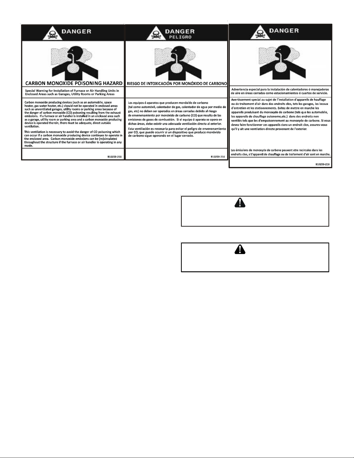
Advertencia especial para la instalación de calentadores ó manejadoras
de aire en áreas cerradas como estacionamientos ó cuartos de servicio.
Las emisiones de monóxido de carbono pueden circular a través
del ap arat o c u ando se opera e n cualquier m odo.
CO can cause serious illness including perman ent brain
damage or death.
S
HIPPING INSPECTION
El monó x i do de carbono p u ede causar en fe r m e dades severa s
como daño cerebral permanente ó muerte.
All units are securely packed in shipping containers tested
according to International Safe Transit Association specifications. The carton must be checked upon arrival for external damage. If damage is found, a request for inspection by carrier’s agent must be made in writing immediately.
Inspect the kit carefully on arrival for damage and bolts or
screws which may have come loose in transit. In the event
of damage the consignee should:
1. Make a notation on delivery receipt of any visible
damage to shipment or container.
2. Notify carrier promptly and request an inspection.
RISQUE D'EMPOISONNEMEN T AU
Cette ventilation est nécessaire pour éviter le danger d'intoxication
au CO pouvant survenir si un appareil produisant du monoxyde
de carbone continue de fonctionner au sein de la zone confinée.
Le monoxyde de
des
dommages perma n e n ts au cerveau et meme la mort.
S
TANDARD AIR HANDLER INSTALLATION
carbone peut causer des maladies graves telles que
MONOXYDE DE CAR BONE
WARNING
TO
PREVENT PERSONAL INJURY OR DEATH WHEN INSTALLING IN A
GARAGE, THE ELEMENT MUST BE AT LEAST
18”
ABOVE THE FLOOR
CAUTION
TO
AVOID PROPERTY DAMAGE OR PERSONAL INJURY DUE TO FIRE, USE
ONLY COPPER CONDUCTORS
.
.
3. With concealed damage, carrier must be notified as
soon as possible - preferably within five days.
4. File the claim with the following support documents
within a nine month statute of limitations.
• Original or certified copy of the Bill of Lading, or
indemnity bond.
• Original paid freight bill or indemnity in lieu thereof.
• Original or certified copy of the invoice, showing
trade and other discounts or reductions.
• Copy of the inspection report issued by carrier’s
representative at the time damage is reported to
carrier.
The carrier is responsible for making prompt inspection of
damage and for a thorough investigation of each claim. The
distributor or manufacturer will not accept claims from dealers for transportation damage.
NOTE: When installing in a garage, the element MUST
be at least 18” above the floor.
1. Remove the upper access panel from the air handler.
2. Remove the block-off plate from the air handler.
3. Slide the heater kit into the slot following the
direction of airflow decal attached to the heater
faceplate and secure using the screws previously
removed.
2
Page 3
NOTE: Steps 4 through 7 and step 10 pertain to kits that
contain circuit breakers.
WARNING
HIGH VOLTAGE !
D
ISCONNECT
ULTIPLE POWER SOURCES MAY BE PRESENT
M
TO DO SO MAY CAUSE PROPERTY DAMAGE, PERSONAL
INJURY OR DEATH
4. Remove the circuit breaker mounting bracket,
5. MBVC and MBR models
ALL
POWER BEFORE SERVICING
.
. F
AILURE
.
leaving the circuit breakers connected.
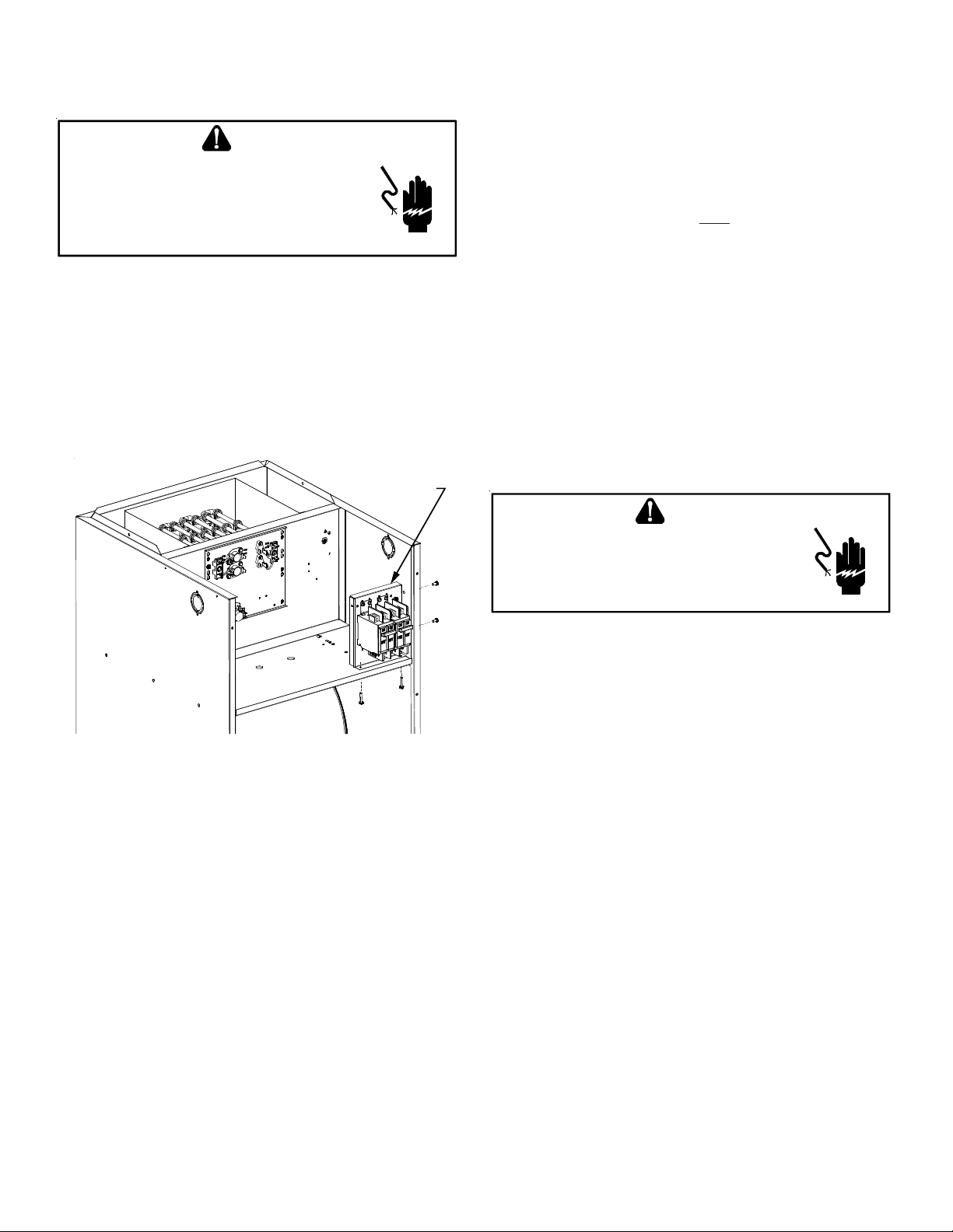
Mount the circuit breaker mounting bracket as shown
using the supplied screws. Insert two of the screws
through the blower deck from the blower side. Insert
the remaining screws in the holes provided on the
upper right side of the jacket.
CIRCUIT
BREAKER
MOUNTING
PLATE
9. Insert the provided ground wire into the lug(s).
10. Remove the screws holding the clear breaker cover
and remove cover. Cut out the insulation to expose
the breaker/breakers. Reinstall the clear plastic
cover with the screws to seal opening.
11. Replace panel and check operation.
12. Apply the wiring diagram
over the one found on the
air handlers. On the “MBVC” Airhandler wiring
diagram which is included, mark an “X” on the wiring
diagram according to the number of Heater Element
rows installed.
13. If installing an HKA heater kit on a unit that only has
the corresponding HKR heater kit shown on the serial
plate, use a permanent marker to add the HKA model
to the serial plate (the data is the same as the HKR).
If the corresponding HKR model number is not on
the serial plate, the heater kit cannot be used.
T
HREE-PHASE UNIT INSTALLATION
WARNING
Figure 1
NOTE: HKA-15C replaces HKR-15C and HKA-20C replaces
HKR-20C in air handlers.
6. Insert the breaker with OFF position oriented down.
NOTE: In the horizontal position, the direction does
not matter. In some cases, it will be easier to wire
the breakers before reinserting them into the
mounting bracket.
7. Insert power leads into the lugs provided on the
circuit breaker and tighten. The power leads MUST
be routed through a strain relief as they enter the
cabinet.
HIGH VOLTAGE !
TO AVOID THE RISK OF ELECTRICAL SHOCK, A MEANS OF
STRAIN RELIEF AND CONDUCTOR PROTECTION MUST BE
PROVIDED AT THE SUPPLY WIRE ENTRANCE
.
1. Follow steps 1 through 4 from “Standard Air Handler
Installation” section.
2. Using the two 1" screws provided, mount the terminal
block on the right hand side of the heater panel on
the airhandler (mounting holes are provided).
3. Wire the terminal block leads to the transformer as
per the wiring diagram.
4. Insert single phase power leads into lugs provided
on the terminal block and tighten.
5. Insert three-phase power leads into lugs provided
on the contactor and tighten. The power leads MUST
be routed through a strain relief as they enter the
cabinet.
6. Follow steps 9, 10, 11 and 12 from “Standard Air
Handler Installation” section.
8. Remove the multi-pin connector with the jumper wire
and discard. Insert the one contained in the kit. It
can be inserted in one position only.
3
Page 4
“H” S
NOTE: A separate power supply is required for the HKR/
ERIES PACKAGE UNIT INSTALLATION
HKP heater kits.
WARNING
HIGH VOLTAGE !
TO AVOID THE RISK OF ELECTRICAL SHOCK, A MEANS OF
STRAIN RELIEF AND CONDUCTOR PROTECTION MUST BE
PROVIDED AT THE SUPPLY WIRE ENTRANCE
1. Disconnect all power to the unit, both indoor and
outdoor.
.
2. Remove the control box cover and blower panel.
3. Remove cover to the electric heat kit box.
4. Break out appropriate knockout for electric heat kit
based on kW of element (# of elements).
5. Remove heater kit from packaging.
For kits that contain circuit breakers:
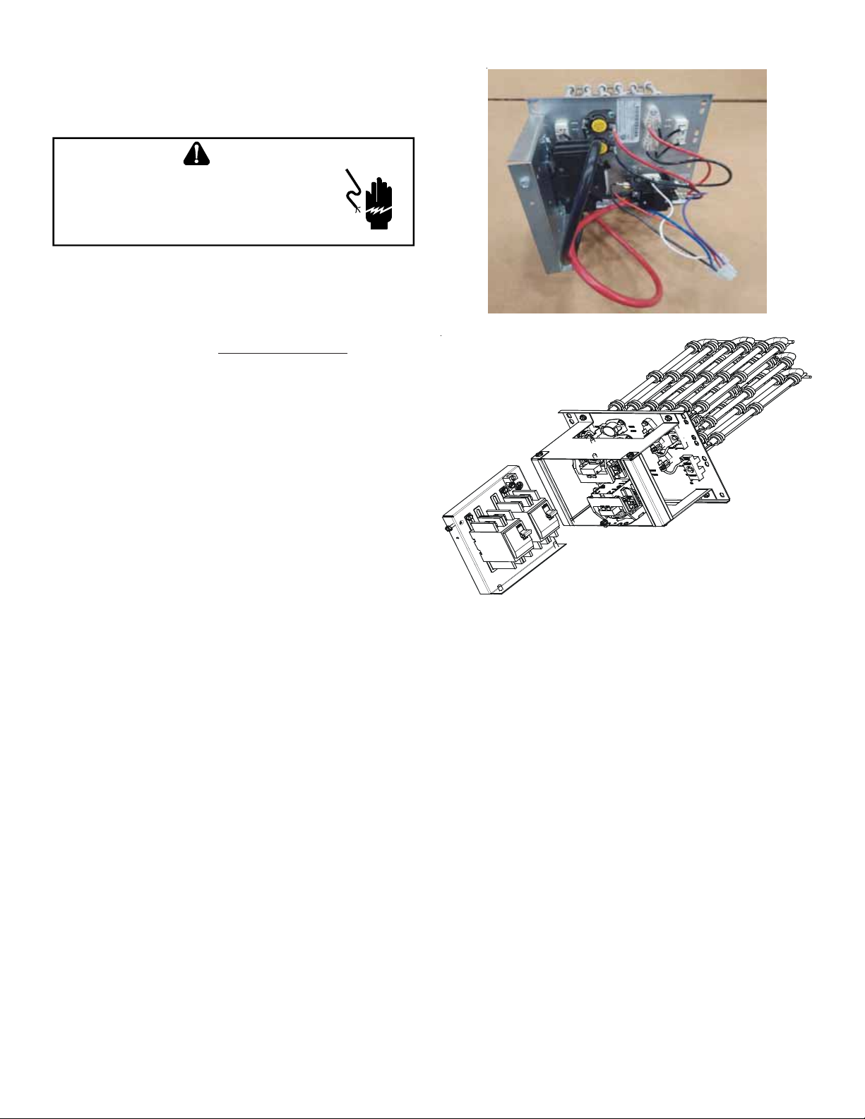
6. Remove screws attaching circuit breaker plate
(Figure 2 and 3).
Figure 2
Figure 3
For 15kW and 20kW kits:
7. Remove screws attaching the contactors (quantity
2) to horseshoe contactor bracket (Figure 4).
4
Page 5

Figure 4
8. Remove four (4) screws attaching the horseshoe
contactor bracket and lift off of heater plate
(Figure 5).
Figure 5
9. Attach contactors to included “H” model vertical
contactor plate. Ensure contactor lugs are pointed
inward towards each other.
10. Slide the heater kit into the slot following the
direction of airflow decal for package unit operation
attached to the heater faceplate and secure with
screws provided.
Figure 6
12. Place vertical contactor bracket behind corner post.
13. Secure vertical contactor plate and heater kit to unit
using remaining two mounting screws (Figure 7).
Figure 7
NOTE: Steps 14 and 17 pertain to kits that contain
circuit breakers.
14. Attach the circuit breaker mounting bracket inside
the top left corner of the electric heat kit box
(Figure 8 and 9). Ensure the breaker is oriented with
OFF position to the left. Remove the two (2) sheet
metal screws prior to installation and re-attach as
shown in Figure 8.
11. Install two of the four mounting screws on heaterkit
(Figure 6).
5
Page 6

Figure 8
CIRCUIT BREAKER
MOUNTING PLATE
Figure 10
16. Remove the protection plug (male plug) and discard.
Insert the one provided in the electric heat kit. It
can be inserted in one position only.
17. Insert the ground wire into the lug(s) provided for
that purpose.
18. Break out the appropriate area of the electric heat
kit cover previously removed for the circuit breaker
provided in the heater kit and replace electric heat
kit cover.
Figure 9
NOTE: In some cases, it will be easier to wire the
breakers BEFORE inserting them into the electric heat
kit box. If rewiring is desired, reference the included
wiring diagram to ensure correct wiring.
15. Insert the power leads into the lugs provided on the
circuit breaker or terminal block and tighten. Ensure
the power leads are routed through the outer cabinet
with a watertight electrical connector, sized
appropriately for the electrical power supply (see
NEC, National Electric Code).
NOTE: To replace the electric heat kit cover , slightly
tip the cover and insert only the notches under the
flanges on the top and bottom of the box. Secure
with screws. See Figure 11.
ATTACH CIRCUIT BREAKER
MOUNTING BRACKET
WITH PROVIDED
SHEET METAL SCREW
ATTACH CIRCUIT BREAKER
MOUNTING BRACK ET
WITH PROVIDED
SHEET METAL SCREW
FLANGE
CIRCUIT
BREAKER
KNOCKOUTS
TIP IN SLIGHTLY
AND SECURE
NOTCHES
BEHIND FLANGE
SCREW
Figure 11
6
Page 7

19. Ensure breaker is in the ON position. Replace blower
panel cover and check operation through the room
thermostat.
20. RESTORE POWER.
21. Apply the provided wiring diagram for package unit
models adjacent to the wiring diagram supplied on
the inside of the unit control box cover.
22. When proper operation is ensured, replace the
control box cover and resume normal operation.
NOTE: In Package Units:
HKP-05C replaces HKR-05C
HKP-10C replaces HKR-10C
HKP-15C replaces HKR-15C
HKP-20C replaces HKR-20C
23. If installing an HKP heater kit on a unit that only has
the corresponding HKR heater kit shown on the serial
plate, use a permanent marker to add the HKP model
to the serial plate (the data is the same as the HKR).
If the corresponding HKR model number is not on
the serial plate, the heater kit can not be used.
“M” S
ERIES PACKAGE UNIT INSTALLATION
NOTE: A separate power supply is required for the HKR
heater kits.
WARNING
HIGH VOLTAGE !
D
ISCONNECT
ULTIPLE POWER SOURCES MAY BE PRESENT
M
TO DO SO MAY CAUSE PROPERTY DAMAGE, PERSONAL
INJURY OR DEATH
ALL
POWER BEFORE SERVICING
.
.
. F
AILURE
Figure 12
5. Remove the two screws holding the rear mounting
plate. Note the orientation of the heater box
covers for reassembly.
NOTE: For “M” Series Package Unit Installations, do not
remove the horseshoe contractor bracket (on
15kW or 20kW heater kits).
6. Three-Phase HKR Kits only
Remove the contactor from the HKR mounting
bracket, leaving the wires connected. Attach
contactor to rear mounting plate as shown in Figure
13.
1. Disconnect all power to the unit, both indoor and
outdoor.
2. Remove control box door.
3. Remove blower door.
4. Locate heater box. Remove the two screws holding
the heater box cover in place (Figure 12).
Figure 13
7. Install heater element(s) with the four (4) pointed
screws included in the unit literature bag. Note the
air flow direction label located on the heater element
base shown in Figures 14 and 15. Orient the heating
element base to match airflow direction on package
unit blower assembly. Ensure scews attaching
horseshoe contactor plate fit into relief cuts of
package unit.
7
Page 8

Figure 14
Figure 15
8. Single Phase HKR Kits only
Mount the breaker (or terminal block) to the rear
mounting plate using the four (4) blunt tip screws
included in the unit literature bag. The screw heads
should all be located on the outside of the mounting
plate as shown in Figure 16.
Figure 16
9. Locate the 9-pin harness in the unit and remove the
male plug (Figures 17 and 18).
Figure 17
Figure 18
10. Connect the 9-pin plug from the unit to the 9-pin
plug in the heater kit.
11. Feed the 9-pin harness wires through the rubber
grommet, and feed the HKR wires through the plastic
bushing in the rear mounting plate. See Figure 19.
Ensure 6 gauge wires are going through heater kit
cover holes. Tuck excess into side of unit and route
wires over top of horshoe plate.
8
Page 9

Figure 19
12. Install rear mounting plate with the two (2) screws
removed in step 5.
13. Connect the line voltage leads to the breaker(s),
terminal block, or contactor as applicable.
14. If heat kit includes breakers, remove rectangular
knockout(s) from outside cover as required for
access.
16. Install control box door and blower door.
17. Reconnect power and test.
NOTE: In Package Units:
HKP-05C replaces HKR-05C
HKP-10C replaces HKR-10C
HKP-15C replaces HKR-15C
HKP-20C replaces HKR-20C
NOTE: If installing an HKP heater kit on a unit that only
has the corresponding HKR heater kit shown on
the serial plate, use a permanent marker to add
the HKP model to the serial plate (the data is the
same as the HKR). If the corresponding HKR model
number is not on the serial plate, the heater kit
can not be used.
NOTE: On earlier (M) models it may be necessary to
notch or cut heater kit shroud to accomodate
screws in heater (Figure 21).
15. Install the cover with the two (2) screws removed in
step 4, routing the line voltage wires through the
rubber grommet as shown in Figure 20.
Figure 20
Figure 21
9
Page 10

NOTE: T o accomodate 6-gauge wires, it may be necessary
to make cuts as shown on the heater kit cover.
Ensure grommet edging is used along sharp edges
to prevent injury (Figure 22).
Figure 22
NOTE: If necessary to connect line power to unit, drill a
1” hole at the coordinates provided in Figure 23.
Figure 23
10
Page 11

THIS PAGE IS INTENTIONALLY LEFT BLANK
11
Page 12

NOTE: SPECIFICATIONS AND PERFORMANCE DATA LISTED HEREIN ARE SUBJECT TO CHANGE WITHOUT NOTICE
Quality Makes the Difference!
All of our systems are designed and manufactured with the same high quality standards regardless of size or efficiency. We have designed these units to significantly reduce the most frequent
causes of product failure. They are simple to service and forgiving to operate. We use quality
materials and components. Finally, every unit is run tested before it leaves the factory. That’s
why we know. . . There’s No Better Quality.”
Visit our website at www.daikincomfort.com, www.goodmanmfg.com or www.amana-hac.com for information on:
• Products
• Warranties
• Customer Services
• Parts
• Contractor Programs and Training
• Financing Options
5151 San Felipe, Suite 500, Houston, TX 77056
© 2003-2007, 2009, 2012-2018 Goodman Manufacturing Company, L.P.
is a registered trademark of Maytag Corporation or its related companies and is used under license. All rights reserved.
12
 Loading...