

Page 1
HANG16, HALP13, HAPS30, HAPS31
HIGH AL TITUDE CONVERSION KIT(S)
INSTALLATION INSTRUCTIONS
Description
This kit contains the appropriate burner orifices, and/or pressure switch for the application of 90% furnaces in installations
above their maximum (as shipped) rated altitudes. These kits
are not applicable in Canada. Kits apply as shown in the
table below.
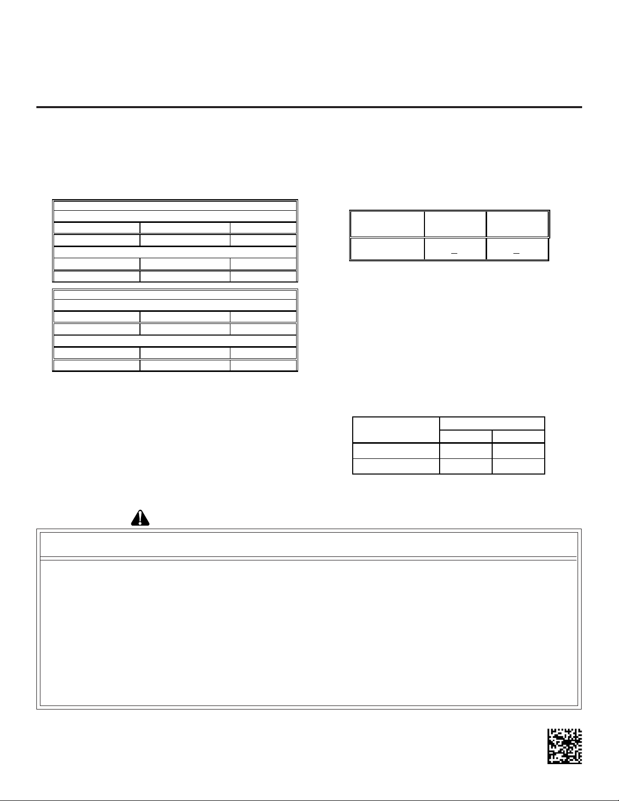
"S tandar d" and "H igh Altitude " Kits
0 - 7,000 Feet (Standa rd Altit u de)
Natural Gas Orifices Propane Gas Orifices Pressure Switch
No Change LPM-06 No Ch an ge
UPFLOWCOUNTERFLOW
Natural Gas Orifices Propane Gas Orifices Pressure Switch
HANG16 HALP13 HAPS30
"S tandar d" and "H igh Altitude " Kits
Natural Gas Orifices Propane Gas Orifices Pressure Switch
No Change LPM-06 No Ch an ge
Natural Gas Orifices Propane Gas Orifices Pressure Switch
HANG16 HALP13 HAPS31
Above an altitude of 7,000 feet, a derating of the appliance
must be followed since the CFM moved by the induced draft
blower remains almost constant while the pounds of oxygen
in that air is reduced as altitude increases. If this procedure
is not followed and the fuel input is not reduced the resulting
combustion can be inefficient, incomplete, or possibly cause
premature heat exchanger failure due to excessive temperature rise. The burner orifices in the high altitude kits have
been selected as a result of agency certified testing at high
altitude and will provide the appropriate derating (Table 2).
7 ,00 1 - 11, 000 Fe et
0 - 7,000 Feet (Standa rd Altit u de)
7 ,00 1 - 11, 000 Fe et
Table 1
Orifice selection is based on non-derated gas [at standard
conditions of 29.92 in Hg and 60°F—approximately 1,000 Btu/
ft3 for natural gas and 2,500 Btu/ft3 for propane]. NOTE:
“Point of use” Btu content will be less due to decreased
atmospheric pressure. If the Btu content of your gas sup-
ply has been artificially changed to account for altitude, contact your gas supplier for orifice sizing.
Alti tu d e (ft)
7,001 - 11,000 24 +
Na tural G as
De rate
2% 33 + 2%
Propa ne
Gas Derate
Table 2
Do not derate by adjusting the manifold pressure to a
lower pressure setting than specified on the furnace
nameplate. A lower air density in combination with a lower
manifold pressure at the burner orifice will prevent the orifice
from aspirating the proper amount of air into the burner required for complete combustion.
In addition to using smaller orifices to reduce the fuel input, a
different pressure switch must be used above the maximum
(as shipped) rated altitude. A high altitude pressure switch is
necessary as a result of the reduction in air density and is
required regardless of the Btu content of the fuel used.
Altitude (ft.)
0 - 7,000 #43 #55
7,001 - 11,000 #44 #56
Burner Orifice Size
Natural Propane
Table 3
IO-686A
September 2013
RECOGNIZE THIS SYMBOL AS A SAFETY PRECAUTION
ATTENTION INSTALLING PERSONNEL
As a professional installer you have an obligation to know the product better than the customer.
This includes all safety precautions and related items.
Prior to actual installation, thoroughly familiarize yourself with this Instruction Manual.
Pay special attention to all safety warnings. Often during installation or repair it is possible to place
yourself in a position which is more hazardous than when the unit is in operation.
Remember, it is your responsibility to install the product safely and to know it
well enough to be able to instruct a customer in its safe use.
Safety is a matter of common sense...a matter of thinking before acting.
Most dealers have a list of specific good safety practices...follow them.
The precautions listed in this Installation Manual are intended as supplemental to existing practices.
However, if there is a direct conflict between existing practices and the content of this manual,
the precautions listed here take precedence.
Page 2
CONTENTS
Important Information.......................................................... 2
HANG16 and HALP13
Orifice Installation HANG16 and HALP13 .................... 3
Gas Manifold Removal ............................................ 3
Burner Orifice Replacement .................................... 3
Gas Manifold Re-Installation ................................... 3
HANG16
Adjustments and Checks............................................ 3
Orifice Leak Check ................................................. 3
Line Pressure Check .............................................. 3
Manifold Pressure Check........................................ 4
Unit Operations Check................................................ 4
Check Normal Operating Sequence
of Ignition System............................................. 4
Verify Gas Input Rates............................................ 4
Inspect Burner Flame ............................................. 5
Check & Adjust Unit
T emperture Rise ............................................... 5
HALP13
Propane Gas Unit Kit Installation ................................ 5
Low Pressure LP Kit Accessory Installation................ 5
Adjustments and Checks............................................ 5
Orifice Leak Check ................................................. 5
Line Pressure Check .............................................. 6
Manifold Pressure Check........................................ 6
Unit Operation Checks................................................ 6
Check Normal Operating Sequence
of Ignition System............................................. 6
Verify Gas Input Rates............................................ 6
Inspect Burner Flame ............................................. 6
Check & Adjust Unit
T emperture Rise ............................................... 6
Label Attachment ................................................... 6
HAPS 30 and HAPS31
Pressure Switch Removal/Replacement...................... 7
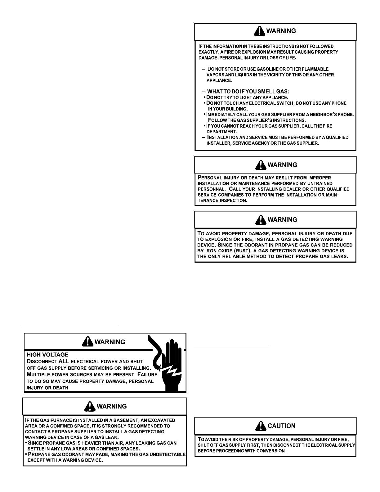
IMPORTANT INFORMA TION
Contact a local propane gas supplier
about installing a gas detecting warning device.
NOTE: T o ensure proper operation, install, operate and main-
tain the unit in accordance with these installation instructions,
all local building codes and ordinances. In their absence,
follow the latest edition of the National Fuel Gas Code (NFP A
54/ANSI Z223.1), and/or CAN/CSA B149.1 Installation Codes.
HANG16 and HALP13
The conversion from “standard altitude” orifices (as shipped
from the factory) to “high altitude” orifices requires:
• Removing gas manifold
• Replacing burner orifices
• Reinstalling gas manifold
Before proceeding, shut OFF gas supply at manual shut-off
and turn off power to the unit.
2
Page 3
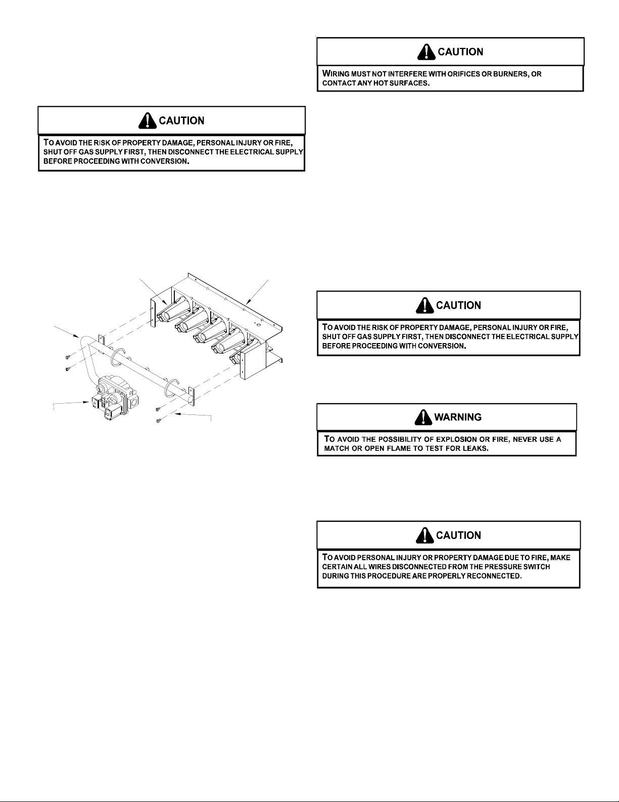
ORIFICE INSTALLATION - HANG16 AND HALP13
r
GAS MANIFOLD REMOVAL
1. Shut OFF gas supply at manual shutoff and turn OFF
power to the unit.
2. Disconnect wiring from the gas valve.
3. Where necessary, cut wire ties securing wiring to manifold.
4. Remove the screws securing the gas manifold and valve to
the burner bracket. Separate gas manifold and valve from
burner bracket.
Burne
Burner Brack et
Manifold
3. Refer to the following sections detailing Adjustments and
Checks for natural gas (HANG16) or Propane Spring
Change for propane gas (HALP13).
ADJUSTMENTS AND CHECKS - HANG16
The following adjustments and checks are a required part of
this ocnversion. Adjustment and checks include:
• Leak checking orifices
• Checking and adjusting line and manifold gas pressures
• V erfying proper unit operation (input rate, operational
sequence, burner flame, temperature rise, etc.)
Before proceeding, shut OFF gas supply at manual shut-off
and turn off power to the unit.
Gas Valve
Ground wire
Figure 1
Gas Manifold Removal
(Upflow shown, counterflow similar)
BURNER ORIFICE REPLACEMENT
1. Remove standard altitude natural gas orifices from gas
manifold using a box end wrench.
2. Install high altitude gas orifices supplied in the high alti-
tude kit. Tighten orifices with a box-end wrench; do not
use a socket wrench as it could damage the orifices; do
not cross-thread or overtighten. Refer to Tables 1 and 2
for the appropriate high altitude kit and orifice size. Ori-
fice usage depends on an installation’s gas usage (natural or propane) and altitude.
GAS MANIFOLD RE-INSTALLATION
1. Reinstall gas manifold and valve. Make certain that the
orifices are inserted in each burner and that each burner
remains properly seated in the burner bracket.
(NOTE: Secure green burner assembly ground wire with
manifold screw).
2. Reconnect wiring to gas valve. Secure wiring to manifold
using wire ties provided.
ORIFICE LEAK CHECK
Leak check burner orifice threads using a soap solution.
LINE PRESSURE CHECK
1. Shut OFF gas at the manual gas shutoff valve and turn
OFF power to the unit.
2. Connect a calibrated water manometer or appropriate gas
pressure gauge at either the gas valve inlet pressure tap
or gas piping drip leg.
3. Turn ON the power and gas, put the unit into heating cycle
and turn on all other gas consuming appliances.
4. Measure the gas supply pressure with the burners firing.
The inlet gas pressure for natural gas should be between
5.0 and 10.0 inches W .C. If supply pressure differs from
required, make necessary adjustments to pressure
regulator(s), gas piping, etc.
3
Page 4

5. T urn OFF gas to the unit at the manual shutof f valve and
disconnect manometer. Reinstall line pressure tap plug.
Turn OFF any unnecessary appliances started in step 3.
Outlet (Manifold)
Pressure Tap
(Side of Valve)
High Manifold
Regulator Adjustment
Screw (Under Cap)
Low Manifold
Regulator Adjustment
Screw (Unde r Cap)
Gas Valve
ON/OFF Switch
Inlet Pressure Tap
(Side of Valve)
Manometer
Hose
Figure 2
White-Rodgers 36E54
MANIFOLD PRESSURE CHECK
Only small variations in gas flow should be made by adjusting
the gas valve pressure regulator. See Table 4 for the required
natural gas manifold pressure.
Natural Ga s Manifold Pre ssure
Low Stage High Sta ge
1.6 to 2. 2" w. c . 3.0 to 3.6" w.c .
Table 4
1. Turn OFF gas to the unit at the manual gas shutoff valve.
2. Connect a calibrated water manometer or appropriate
gas pressure gauge at the gas valve outlet pressure tap.
3. Turn ON gas supply and operate unit.
4. Remove the cap screw from the high stage manifold
pressure regulator adjustment location.
5. Using an Allen wrench, adjust high stage manifold regu-
lator to the required manifold pressure (T able 4).
6. Reinstall the high stage manifold pressure regulator cap
screw. Confirm high st age manifold pressure.
7. Remove the cap screw from the low stage manifold pres-
sure regulator adjustment location.
8. Using an Allen wrench, adjust low stage manifold regulator to the required manifold pressure.
9. Reinstall the low st age manifold regulator cap screw.
Confirm low stage manifold pressure.
10. Turn OFF gas supply to unit. Disconnect manometer
and reinstall manifold pressure tap plug.
UNIT OPERATION CHECKS - HANG16
CHECK NORMAL OPERATING SEQUENCE
OF IGNITION SYSTEM
Check the normal operating sequence of the ignition system to
ensure burners light properly.
VERIFY GAS INPUT RATE(S)
1. Turn OFF gas supply to all other gas-burning appliances
except the furnace.
2. Install jumper wires between the R and W1 and the R
and W2 terminals of the integrated control module to initiate and maintain furnace operation on high stage heat.
3. While the furnace is operating on high stage, record the
time required (in seconds) for one complete revolution of
the small gas meter dial.
4. Calculate the number of seconds per cubic foot (sec/ft3) of
gas being delivered to the furnace. If the dial is a one-cubic
foot dial, divide the number of seconds recorded in step 3
by 1. If the dial is a two-cubic foot dial, divide the number of
seconds recorded in step 2 by 2.
5. Calculate the furnace input rate (high stage) in BTUs per
hour (Btu/hr). Input equals in the sum of: the installation’s
heating value and a conversion factor (hours to seconds)
divided by the number of seconds per cubic foot. The measured input must agree with the expected input calculated
in step 6.
INPUT CALCULATION EXAMPLE:
Installation’s gas heating value (from gas supplier)
1,000 Btu/ft3 (at standard conditions)
720 Btu/ft3 (at elevation)
Installation’s seconds per cubic foot: 30 sec/ft
3
Conversion Factor (hours to seconds): 3600 sec/hr
Input = (Htg. value x 3600) ÷ seconds per cubic foot
Input = (720 Btu/ft3 x 3600 sec/hr) ÷ 30 sec/ ft
3
Input = 86,400 Btu/hr (high stage)
This measured input must agree with the derates for your
unit and altitude as indicated in Table 2.
6. Compare measured input rate with expected input resulting from altitude derate.
Derating Example 1: 11,500 BTU at 9,000 ft.
Sea level (high stage) input = 115,000 Btu/hr
From Table 2: Derate at 9,000 ft. = 24 ± 2%
Since this installation is approximately at the mid point
of the elevation range, use the mid point of the derate:
24%.
Expected Input = 115,000 x (1 - .24) = 87,400 Btu/hr
4
Page 5

Derating Example 2: 11,500 BTU at 7,501 ft.
Sea level (high stage) input = 115,000 Btu/hr
From Table 2: Derate at 7,001 ft. = 24 ± 2%
Since this installation is at the lower end of the elevation
range, use the lower derate:
(24 - 2) = 22%.
Expected Input = 115,000 x (1 - .22) = 89,700 Btu/hr
7. Remove jumper wires from integrated control module.
INSPECT BURNER FLAME
The burner flames should be stable, soft and blue (dust may
cause orange tips but they must not be yellow). They should
extend directly outward from the burners without curling, floating, or lifting off.
Check t he burner flam es for:
1. Good adjustment
2. Stable, soft and blue
3. Not curling, floating, or lifting off.
Figure 3
Burner Flame
CHECK AND ADJUST UNIT TEMPERATURE RISE
Check and adjust unit temperature rise(s) as described in the
installation manual.
Temperature rise must be within the range shown on the furnace rating plate.
PROP ANE GAS UNIT KIT INST ALLA TION - HALP13
IMPORTANT: Propane gas is heavier than air and does not
vent upward as natural gas fuels.
LOW PRESSURE LP KIT ACCESSORY INSTALLATION HALP13
To guard against poor burner flame and possible sooting, install a Low Pressure LP kit (LPLP01). Follow the directions
outlined in the instructions provided with the kit.
ADJUSTMENT AND CHECKS - HALP13
The following adjustments and checks are a required part of
this conversion. Adjustments and checks include:
• Leak checking orifices
• Checking and adjusting line and manifold gas pres-
sures
• Verifying proper unit operation (input rate, operational
sequence, burner flame, temperature rise, etc.)
ORIFICE LEAK CHECK
Leak check burner orifice threads using a soap solution.
5
Page 6

LINE PRESSURE CHECK
1. Shut OFF gas at the manual gas shutoff valve and turn
OFF power to the unit.
2. Connect a calibrated water manometer or appropriate gas
pressure gauge at either the gas valve inlet pressure tap
or gas piping drip leg (Figure 2).
3. Turn ON the power and gas, put the unit into heating cycle
and turn on all other gas consuming appliances.
4. Measure the gas supply pressure with the burners firing.
The inlet gas pressure for propane gas must be between
11.0 and 13.0 inches W.C. If supply pressure differs
from required, make necessary adjustments to pressure
regulator(s), gas piping, etc.
5. Turn OFF gas to the unit at the manual shutoff valve and
disconnect manometer. Reinstall line pressure tap plug.
Turn OFF any unnecessary appliances started in step 3.
MANIFOLD PRESSURE CHECK
Only small variations in gas flow should be made by adjusting
the gas valve pressure regulator. See Table 5 for the required
propane gas manifold pressure.
UNIT OPERA TION CHECK - HALPS13
CHECK NORMAL OPERATING SEQUENCE OF
IGNTION SYSTEM
Check the normal operating sequence of the ignition system
to ensure burners light properly.
VERIFY GAS INPUT RATE(S)
Ensure that the appropriate orifices have been installed and
the manifold pressure has been set as specified in these instructions.
INSPECT BURNER FLAME
The burner flames should be stable, soft and blue (dust may
cause orange tips but they must not be yellow). They should
extend directly outward from the burners without curling, floating, or lifting off.
CHECK AND ADJUST UNIT TEMPERATURE RISE
Check and adjust unit temperature rises as described in the
installation manual.
Temperature rise must be within the range shown on the furnace rating plate.
LABEL ATTACHMENT
Attach conversion data plate, with correct input rating, adjacent to the unit rating plate. Use Table 6 to determine the
correct data plate to be applied.
Propane Gas Manifold Pressure
Low Stage High Stage
5.7 to 6.3" w.c. 9.7 to 10.3" w.c.
Table 5
1. Turn OFF gas to the unit at the manual gas shutoff valve.
2. Connect a calibrated water manometer or appropriate gas
pressure gauge at the gas valve outlet pressure tap.
3. Turn ON gas supply and operate unit.
4. Remove the cap screw from the high stage manifold pressure regulator adjustment location.
5. Using an Allen wrench, adjust high stage manifold regula-
tor to the required manifold pressure (T able 5).
6. Reinstall the high stage manifold pressure regulator cap
screw. Confirm high stage manifold pressure.
7. Remove the cap screw from the low stage manifold pressure regulator adjustment location.
8. Using an Allen wrench, adjust low stage manifold regulator
to the required manifold pressure.
9. Reinstall the low stage manifold regulator cap screw . Confirm low stage manifold pressure.
10. Turn OFF gas supply to unit. Disconnect manometer and
reinstall manifold pressure tap plug.
INPUT RATING
(Propane Gas: Standard Altitude)
Size Input (Btu/hr)
045 33,500
070 50,300
091 67,000
115 83,800
Table 6
Post “conversion date certificate” adjacent to the unit rating
plate.
HAPS30 and HAPS31
The conversion from “standard altitude” pressure switch assembly (as shipped from the factory) to “high altitude” pressure switch assembly requires:
• Removing standard altitude pressure switch
• Installing high altitude pressure switch
Before proceeding, shut OFF gas supply at manual shut-off
and turn OFF power to the unit.
6
Page 7

PRESSURE SWITCH REMOVAL/REPLACEMENT
1. Shut OFF gas supply at manual shutoff and turn OFF
power to the unit.
2. Locate induced draft blower two-stage pressure switch
assembly.
3. Disconnect the pressure switch hose from the pressure
switch assembly tee.
4. Disconnect high stage (yellow and orange) and low stage
(red and blue) wiring from pressure switches.
5. Remove mounting bracket screw securing standard altitude pressure switch assembly to partition panel.
6. Install high altitude pressure switch assembly using
screw removed in step 5. Refer to Table 7 for proper
pressure switch kit.
7. Reconnect wiring to pressure switches.
8. Reconnect pressure switch hose to new assembly.
9. V erify proper furnace operation.
Two-Stage
Pressure
Switch
Red/Blue
Yellow/Orange,
Electrical
Connections
Induced Draft
Blower
Pressure Switch
Hoses
Figure 4
Induced Draft Blower
Pressure Switch Location
(Upflow shown, Counterflow similar)
7,001 - 11,000 ft.
Kit
HAPS30 11177119 -0.15 -0.46
HAPS31 11177120 -0.15 -0.30
Pressure
Switch
Low Stage High Stage
Set Point
Table 7
Pressure Switch
7
Page 8

NOTE: SPECIFICATIONS AND PERFORMANCE DATA LISTED HEREIN ARE SUBJECT TO CHANGE WITHOUT NOTICE
®
Quality Makes the Difference!
All of our systems are designed and manufactured with the same high quality standards regardless of size or efficiency. We have designed these units to significantly reduce the most frequent causes of product failure. They are
simple to service and forgiving to operate. We use quality materials and components. Finally, every unit is run tested
before it leaves the factory. That’ s why we know. . .There’ s No Better Quality.
Visit our website at www.daikincomfort.com, www.goodmanmfg.com or www.amana-hac.com for information on:
• Products
• Warranties
• Customer Services
Goodman Manufacturing Company, L.P.
5151 San Felipe, Suite 500, Houston, TX 77056
© 2002 - 2007, 2013 Goodman Manufacturing Company, L.P.
is a trademark of Maytag Corporation and is used under license. All rights reserved.
• Parts
• Contractor Programs and Training
• Financing Options
8
 Loading...