

Page 1
I
NSTALLA TION
I
NSTRUCTIONS FOR
*MES96
INGLE-STAGE
S
(T ype FSP CA TEGOR Y IV Direct
or Non Direct V ent Air Furnace)
These furnaces comply with requirements embodied in the American National Standard/National Standard of Canada ANSI Z21.47·CSA-2.3
Gas Fired Central Furnaces.
As a professional installer you have an obligation to know
the product better than the customer . This includes all safety
precautions and related items.
Prior to actual installation, thoroughly familiarize yourself
with this Instruction Manual. Pay special attention to all
safety warnings. Often during installation or repair it is
possible to place yourself in a position which is more
hazardous than when the unit is in operation.
Remember, it is your responsibility to install the product
safely and to know it well enough to be able to instruct a
customer in its safe use.
Safety is a matter of common sense...a matter of thinking
before acting. Most dealers have a list of specific good
safety practices...follow them.
The precautions listed in this Installation Manual are intended
as supplemental to existing practices. However, if there is
a direct conflict between existing practices and the content
of this manual, the precautions listed here take precedence.
RECOGNIZE THIS SYMBOL
AS A SAFETY PRECAUTION.
*NOTE: Please contact your distributor or our website for
the applicable Specification Sheet referred to in this manual.
GAS F
Affix all manuals
adjacent to the unit.
URNACE
Installer:
O
NLY PERSONNEL THAT HAVE BEEN TRAINED TO INSTALL, ADJUST, SERVICE OR
REPAIR (HEREINAFTER
SHOULD SERVICE THE EQUIPMENT
FOR ANY INJURY OR PROPERTY DAMAGE ARISING FROM IMPROPER SERVICE OR
SERVICE PROCEDURES
FOR ANY INJURY OR PROPERTY DAMAGE WHICH MAY RESULT
JURISDICTIONS THAT REQUIRE ONE OR MORE LICENSES TO SERVICE THE EQUIPMENT
SPECIFIED IN THIS MANUAL, ONLY LICENSED PERSONNEL SHOULD SERVICE THE
EQUIPMENT
THE EQUIPMENT SPECIFIED IN THIS MANUAL, OR ATTEMPTING TO INSTALL, ADJUST
SERVICE OR REPAIR THE EQUIPMENT SPECIFIED IN THIS MANUAL WITHOUT PROPER
TRAINING MAY RESULT IN PRODUCT DAMAGE, PROPERTY DAMAGE, PERSONAL
INJURY OR DEATH
, “
SERVICE
”)
THE EQUIPMENT SPECIFIED IN THIS MANUAL
. THE
MANUFACTURER WILL NOT BE RESPONSIBLE
. IF
YOU SERVICE THIS UNIT, YOU ASSUME RESPONSIBILITY
. IN
ADDITION, IN
. I
MPROPER INSTALLATION, ADJUSTM ENT, SERVICING OR REPAIR OF
.
PROP 65 WARNING
FOR CALIFORNIA CONSUMERS
Cancer and Reproductive Harm -
www.P65Warnings.ca.gov
0140M00517-A
TABLE OF CONTENTS
SAFETY CONSIDERATIONS .......................................... 2
SHIPPING INSPECTION ............................................ 4
ELECTROST ATIC DISCHARGE (ESD) PRECAUTIONS.................... 4
TO THE INSTALLER ............................................. 5
PRODUCT APPLICATION ............................................. 5
LOCA TION REQUIREMENTS & CONSIDERATIONS......................... 5
CLEARANCES AND ACCESSIBILITY ................................... 6
EXISTING FURNACE REMOVAL ..................................... 7
THERMOSTAT LOCATION .......................................... 7
COMBUSTION & VENTILATION AIR REQUIREMENTS ..................... 8
INSTALLATION POSITIONS ............................................ 8
HORIZONTAL APPLICATIONS & CONSIDERATIONS ........................ 8
FURNACE SUSPENSION ........................................... 8
FRONT COVER PRESSURE SWITCH TUBE LOCATION ................. 9
DRAIN TRAP AND LINES ......................................... 9
LEVELING ...................................................... 9
ALTERNATIVE VENT/FLUE AND COMBUSTION AIR CONNECTIONS ...... 9
ALTERNATE ELECTRICAL AND GAS LINE CONNECTIONS ............... 9
DRAIN PAN .................................................... 9
FREEZE PROTECTION ............................................ 9
HIGH ALTITUDE INSTALLATION .................................... 9
VENT/FLUE PIPE & COMBUSTION AIR PIPE .......................... 9
DUAL CERTIFICATION: NON-DIRECT/DIRECT VENT .................10
MATERIALS AND JOINING METHODS ..............................10
PROPER VENT/FLUE AND COMBUSTION AIR PIPING PRACTICES ...... 10
TERMINATION LOCATIONS ........................................11
STANDARD FURNACE CONNECTIONS ..............................12
VENT/FLUE PIPE ..............................................12
,
IOG-2013B
07/2019
5151 San Felipe Suite 500
Houston, TX 77056
www.goodmanmfg.com • www.amana-hac.com
© 2014-2019 Goodman Manufacturing Company, L.P.
is a registered trademark of Maytag Corporation or its related companies
and is used under license. All rights reserved.
Page 2

OMBUSTION AIR PIPE ............................................12
C
DIRECT VENT INSTALLATIONS ....................................12
NON-DIRECT VENT INSTALLATIONS ...............................13
AL TERNATE VENT/FLUE LOCATION .................................13
AL TERNATE COMBUSTION AIR PROVISION ..........................13
NON-DIRECT VENT (SINGLE PIPE) PIPING ........................13
VENT/FLUE PIPE LENGTHS AND DIAMETERS ......................14
MAXIMUM ALLOWABLE VENT LENGTH OF VENT/FLUE PIPE &
C
OMBUSTION AIR PIPE (FT) ....................................14
VENT/FLUE PIPE TERMINA TIONS.................................14
DIRECT VENT (DUAL PIPE) PIPING ..............................16
VENT/FLUE COMBUSTION AIR PIPE LENGTHS & DIAMETERS ........16
VENT/FLUE AND COMBUSTION AIR PIPE TERMINATIONS ............16
VENT/INTAKE TERMINATIONS FOR INST ALLATIONS OF MULTIPLE DIRECT
VENT FURNACES ...............................................17
CONCENTRIC VENT TERMINATION.................................17
SIDE WALL VENT KIT..........................................17
CONDENSATE DRAIN LINES & DRAIN TRAP ..........................17
GENERAL DRAIN INFORMATION...................................18
FIELD SUPPLIED DRAIN .........................................18
UPFLOW MODEL INSTALLED VERTICALLY ..........................18
DRAIN EXITING RIGHT SIDE .....................................19
DRAIN EXITING LEFT SIDE ......................................19
UPFLOW MODEL INSTALLED HORIZONTALLY W/ RIGHT SIDE DOWN .19
UPFLOW MODEL INSTALLED HORIZONTALLY W/ LEFT SIDE DOWN . 19
UPFLOW MODEL INSTALLED HORIZONTALLY W/ LEFT SIDE DOWN -
AL TERNATE ....................................................20
ELECTRICAL CONNECTIONS .........................................20
WIRING HARNESS ..............................................20
115 VOLT LINE CONNECTIONS OF ACCESSORIES
(HUMIDIFIER AND ELECTRONIC AIR CLEANER) .....................21
JUNCTION BOX RELOCATION.....................................21
24 VOLT THERMOSTAT WIRING..................................22
SINGLE-STAGE HEA TING THERMOSTAT APPLICATION ................22
FOSSIL FUEL APPLICA TIONS......................................22
GAS SUPPLY AND PIPING .......................................22
HIGH ALTITUDE DERATE ........................................22
GAS VALVE ...................................................22
GAS PIPING CONNECTIONS ......................................23
GAS PIPING CHECKS ...........................................24
CIRCULA TING AIR & FILTERS .......................................24
DUCT WORK - AIR FLOW .......................................24
CHECKING DUCT STATIC ........................................25
BOTTOM RETURN AIR OPENING [UPFLOW MODELS]...............25
FILTERS - READ THIS SECTION BEFORE INSTALLING
THE RETURN AIR DUCT WORK ...............................26
HORIZONT AL INSTALLATIONS .....................................27
STARTUP PROCEDURE & ADJUSTMENT ..............................27
DRAIN TRAP PRIMING ..........................................27
FURNACE OPERATION ...........................................27
FURNACE ST A RTUP .............................................27
FURNACE SHUTDOWN ..........................................27
GAS SUPPLY PRESSURE MEASUREMENT ...........................27
GAS PRESSURE TEST ...........................................27
GAS MANIFOLD PRESSURE MEASUREMENT AND ADJUSTMENT ........28
GAS INPUT RATE MEASUREMENT (NATURAL GAS ONLY) ...........29
TEMPERA TURE RISE ............................................29
CIRCULATOR BLOWER SPEEDS ...................................29
BLOWER SPEED ADJUSTMENT ...................................30
LOWER HEAT OFF DELAY TIMINGS .............................30
B
NORMAL SEQUENCE OF OPERATION .................................30
POWER UP ...................................................30
HEATING MODE ...............................................30
COOLING MODE ...............................................30
FAN ONLY MODE .............................................30
OPERA TIONAL CHECKS ............................................31
SAFETY CIRCUIT DESCRIPTION ......................................31
I
NTEGRATED CONTROL MODULE .................................31
PRIMARY LIMIT .................................................31
AUXILIARY LIMIT ...............................................31
BURNER TEMPERATURE SWITCH ..................................31
PRESSURE SENSOR .............................................31
PRESSURE SWITCHES ...........................................31
FLAME SENSOR ................................................31
TROUBLESHOOTING ...............................................31
ELECTROST ATIC DISCHARGE (ESD) PRECAUTIONS...................31
DIAGNOSTIC CHART ............................................32
FAULT CODE RETRIEVAL........................................32
CLEAR FAULT MEMORY .........................................32
RESETTING FROM LOCKOUT .....................................32
MAINTENANCE ...................................................32
ANNUAL INSPECTION ...........................................32
FILTERS .......................................................32
FILTERS MAINTENANCE ..........................................32
FILTER REMOVAL ..............................................32
HORIZONTIAL UNIT FILTER REMOVAL .............................33
MEDIA AIR FILTER OR ELECTRONIC AIR CLEANER REMOVAL .........33
BURNER ......................................................33
INDUCED DRAFT AND CIRCULATOR BLOWERS ......................33
CONDENSATE TRAP AND DRAIN SYSTEM (QUALIFIED SERVICER ONLY)33
FLAME SENSOR (QUALIFIED SERVICER ONLY) .....................33
FLUE PASSAGES (QUALIFIED SERVICER ONLY).....................33
BEFORE LEAVING AN INSTALLATION .................................33
REPAIR AND REPLACEMENT PARTS ..................................33
TROUBLESHOOTING CHART ........................................34
AIRFLOW *MES96*** ........................................... 37
WIRING DIAGRAM *MES96***....................................38
S
AFETY
C
ONSIDERATIONS
IMPORTANT NOTE: This unit is designed to meet the NOx
requirement of 14Ng/J maximum as required by the South
Coast Air Quality Management District and the San Joaquin
V alley Air P ollution Control District, both in the State of California, and is intended for installation in those districts
only.
This unit has a control system that compensates for certain
installation and environmental conditions. This unit must:
• Be properly installed, operated, and maintained per
the instructions.
• Be serviced only by properly trained service
technicians.
Units that are not installed, maintained, or operated properly may result in “noisy” operation during the heating cycle.
If this unit is making unusual or objectionable noises during the heating cycle, turn the heat off at the thermostat
and contact a qualified service organization right away .
Page 3
Adhere to the following warnings and cautions when installing, adjusting, altering, servicing, or operating the furnace.
T o ensure proper installation and operation, thoroughly read
this manual for specifics pertaining to the installation and
application of this product.
This furnace is manufactured for use with natural gas only .
Install this furnace only in a location and position as speci-
fied in LOCA TION REQUIREMENTS & CONSIDERATIONS sec-
tion and INSTALLATION POSITIONS section of this manual.
Provide adequate combustion and ventilation air to the furnace as specified in
COMBUSTION & VENTILATION AIR RE-
QUIREMENTS section of this manual.
Combustion products must be discharged to the outdoors.
Connect this furnace to an approved vent system only, as
specified in VENT/FLUE PIPE & COMBUSTION AIR PIPE section of this manual.
Never test for gas leaks with an open flame. Use a commercially available soap solution made specifically for the detection of leaks to check all connections, as specified in GAS
SUPPLY AND PIPING section of this manual.
Always install a furnace to operate within the furnace’ s intended temperature-rise range with a duct system which has
external static pressure within the allowable range, as specified on the furnace rating plate and OPERATIONAL CHECKS
section of these instructions.
When a furnace is installed so that supply ducts carry air
circulated by the furnace to areas outside the space containing the furnace, the return air shall also be handled by duct(s)
sealed to the furnace casing and terminating outside the
space containing the furnace.
A gas-fired furnace for installation in a residential garage
must be installed as specified in the LOCATION REQUIRE-
MENTS AND CONSIDERATIONS section of this manual.
This furnace cannot be used as a construction site heater .
CAUTION
FROZEN AND BURST WATER PIPE HAZARD
AILURE TO PROTECT AGAINST THE RISK OF FREEZING MAY RESULT IN
F
PROPERTY DAMAGE
PECIAL PRECAUTIONS
S
AREA WHICH MAY DROP BELOW FREEZING
OPERATION OR DAMAGE TO EQUIPMENT
ENVIRONMENT HAS THE POTENTIAL OF FREEZING, THE DRAIN TRAP AND
DRAIN LINE MUST BE PROTECTED
HEATERS, ELECTRIC HEAT TAPE AND/OR
RECOMMENDED FOR THESE INSTALLATIONS
.
MUST BE
MADE IF INSTALLING FURNACE IN AN
. T
HIS CAN CAUS E IMPROPER
. IF
THE FURNACE
. THE
USE OF ACCESSORY DRAIN TRAP
RV
ANTIFREEZE IS
.
WARNING
TO
PREVENT PERSONAL INJURY OR DEATH DUE TO IMPROPER
INSTALLATION, ADJUSTMENT, ALTERATION, SERVICE OR MAINTENANCE
REFER TO THIS MANUAL
INFORMATION, CONSU LT A QUALIFIED INSTALLER, SERVICER AGENCY OR
THE GAS SUPPLIER
. FOR
ADDITIONAL ASSISTANCE OR
.
WARNING
IF
THE INFORMATION IN THESE INSTRUCTIONS IS NOT FOLLOWED
EXACTLY, A FIRE OR EXPLOSION MAY RESULT CAUSING PROPERTY
DAMAGE
,
PERSONAL INJURY OR LOSS OF LIFE
DO
NOT STORE OR USE GASOLINE OR OTHER FLAMMABLE VAPORS AND
LIQUIDS IN THE VICINITY OF THIS OR ANY OTHER APPLIANCE
.
.
WHAT TO DO IF YOU SMELL GAS:
D
O NOT TRY TO LIGHT ANY APPLIANCE
D
O NOT TOUCH ANY ELECTRICAL SWITCH; DO NOT USE ANY PHONE
IN YOUR BUILDING
I
MMEDIATELY CALL YOUR GAS SUPPLIER FROM A NEIGHBOR’S
PHONE
. F
I
F YOU CANNOT REACH YOUR GAS SUPPLIER, CALL THE FIRE
DEPARTMENT
I
NSTALLATION AND SERVICE MUST BE PERFORMED BY A QUALIFIED
INSTALLER, SERVICE AGENCY OR THE GAS SUPPLIER
.
OLLOW THE GAS SUPPLIER’S INSTRUCTIONS
.
.
.
.
WARNING
T
HIS PRODUCT CONTAINS OR PRODUCES A CHEMICAL OR CHEMICALS
WHICH MAY CAUSE SERIOUS ILLNESS OR DEATH AND WHICH ARE
KNOWN TO THE STATE OF CALIFORNIA TO CAUSE CANCER, BIRTH
DEFECTS OR OTHER REPRODUCTIVE HARM
.
WARNING
H
EATING UNIT SHOULD NOT BE UTILIZED WITHOUT REASONABLE
ROUTINE, INSPECTION, MAINTENANCE AND SUPERVISION
BUILDING IN WHICH ANY SUCH DEVICE IS LOCATED WILL BE VACANT
CARE SHOULD BE TAKEN THAT SUCH DEVICE IS ROUTINELY INSPECTED
MAINTAINED AND MONITORED. IN THE EVENT THAT THE BUILDING
MAYBE EXPOSED TO FREEZING TEMPERATURES AND WILL BE VACANT
ALL WATER-BEARING PIPES SHOULD BE DRAINED, THE BUILDING SHOULD
BE PROPERLY WINTERIZED, AND THE WATER SOURCE CLOSED. IN THE
EVENT THAT THE BUILDING MAY BE EXPOSED TO FREEZING
TEMPERATURES AND WILL BE VACANT, ANY HYDRONIC COIL UNITS
SHOULD BE DRAINED AS WELL AND, IN SUCH CASE, ALTERNATIVE HEAT
SOURCES SHOULD BE UTILIZED
.
. IF
THE
,
,
,
,
,
3
Page 4
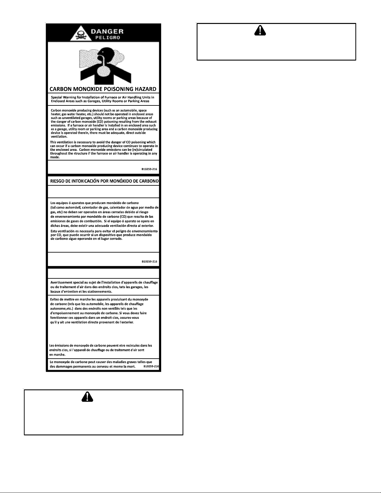
CO can caus e serious illness inc luding permanent brain
damage or death.
Advertenc ia especial para la instala ción de calentadores ó manejadoras
de aire en áreas cerradas como estaci onamientos ó cuartos de servicio.
Las emi siones de monóxid o de carbono p ueden circular a tr avés
del aparato cuando se opera e n cualquier modo .
El monóxido de carbono puede causar enfermedades severas
como daño cerebral permanente ó muerte.
RISQUE D'EMPOISONNEMENT AU
MONOXYDE DE CARBONE
WARNING
S
HOULD OVERHEATING OCCUR OR THE GAS SUPPLY FAIL TO SHUT OFF
TURN OFF THE MANUAL GAS SHUTOFF VALVE EXTERNAL TO THE
FURNACE BEFORE TURNING OFF THE ELECTRICAL SUPPLY
.
,
SHIPPING INSPECTION
All units are securely packed in shipping containers tested according to International Safe T ransit Association specifications.
The carton must be checked upon arrival for external damage.
If damage is found, a request for inspection by carrier’ s agent
must be made in writing immediately .
The furnace must be carefully inspected on arrival for damage
and bolts or screws which may have come loose in transit. In
the event of damage the consignee should:
1. Make a notation on delivery receipt of any visible damage
to shipment or container .
2. Notify carrier promptly and request an inspection.
3. With concealed damage, carrier must be notified as soon
as possible - preferably within five days.
4. File the claim with the following support documents within
a nine month statute of limitations.
• Original or certified copy of the Bill of Lading, or
indemnity bond.
• Original paid freight bill or indemnity in lieu thereof.
• Original or certified copy of the invoice, showing trade
and other discounts or reductions.
• Copy of the inspection report issued by carrier’s
representative at the time damage is reported to carrier .
The carrier is responsible for making prompt inspection of damage and for a thorough investigation of each claim. The distributor or manufacturer will not accept claims from dealers for
transportation damage.
Cette ventilation est nécessaire pour éviter le danger d'intoxication
au CO po uvant survenir si u n appareil produi sant du monoxyde
de carbo ne continue de fon ctionner au sein de la zone confinée.
WARNING
P
OSSIBLE PROPERTY DAMAGE, PERSONAL INJURY OR DEATH DUE TO
FIRE, EXPLOSION, SMOKE, SOOT, CONDENSATION, ELECTRICAL SHOCK
OR CARBO N MONOXIDE MAY RESULT FROM IMPROPER INSTALLATION
REPAIR OPERATION, OR MAINTENANCE OF THIS PRODUCT
.
ELECTROSTATIC DISCHARGE (ESD) PRECAUTIONS
NOTE: Discharge your body’s static electricity before touching
unit. An electrostatic discharge can adversely affect electrical
components.
Use the following precautions during furnace installation and
servicing to protect the integrated control module from damage. By putting the furnace, the control, and the person at the
sam e electrostatic potential, these steps will help avoid exposing the integrated control module to electrostatic discharge. This procedure is applicable to both installed and
non-installed (ungrounded) furnaces.
1. Disconnect all power to the furnace. Do not touch the
,
integrated control module or any wire connected to the
control prior to discharging your body’s electrostatic
charge to ground.
2. Firmly touch a clean, unpainted, metal surface of the
furnaces near the control. Any tools held in a person’ s
hand during grounding will be discharged.
4
Page 5
3. Service integrated control module or connecting wiring
following the discharge process in step 2. Use caution not
to recharge your body with static electricity; (i.e., do not
move or shuffle your feet, do not touch ungrounded
objects, etc.). If you come in contact with an ungrounded
object, repeat step 2 before touching control or wires.
4. Discharge your body to ground before removing a new
control from its container. Follow steps 1 through 3 if
installing the control on a furnace. Return any old or new
controls to their containers before touching any ungrounded
object.
TO THE INSTALLER
Before installing this unit, please read this manual thoroughly to
familiarize yourself with specific items which must be adhered
to, including but not limited to: unit maximum external static
pressure, gas pressures, BTU input rating, proper electrical connections, circulating air temperature rise, minimum or maximum CFM, and motor speed connections.
Dual certification means that the combustion air inlet pipe is
optional and the furnace can be vented as a:
• Non-direct vent (single pipe) central forced air furnace
in which combustion air is taken from the installation
area or from air ducted from the outside or ,
• Direct vent (dual pipe) central forced air furnace in
which all combustion air supplied directly to the furnace
burners through a special air intake system outlined in
these instructions.
This furnace cannot be used as a construction site heater .
T o ensure proper furnace operation, install, oper ate and maintain the furnace in accordance with these installation and
operation instructions, all local building codes and ordinances.
In their absence, follow the latest edition of the National Fuel
Gas Code (NFP A 54/ANSI Z223.1), Installation Codes, local plumbing or waste water codes, and other applicable codes.
WARNING
TO
PREVENT PROPERTY DAMAGE, PERSONAL INJURY OR DEATH DUE TO
FIRE, DO NOT INSTALL THIS FURNACE IN A MOBILE HOME, TRAILER, OR
RECREATIONAL VEHICLE
P
RODUCT APPLICA TION
.
This furnace is primarily designed for residential home-heating
applications. It is NOT designed or certified for use in mobile
homes, trailers or recreational vehicles. Neither is it designed
or certified for outdoor applications. The furnace must be installed indoors (i.e., attic space, crawl space, or garage area
provided the garage area is enclosed with an operating door).
This furnace can be used in the following non-industrial commercial applications:
Schools, Office buildings, Churches, Retail stores, Nursing
homes, Hotels/motels, Common or office areas.
In such applications, the furnace must be installed with the following stipulations:
• It must be installed per the installation instructions
provided and per local and national codes.
• It must be installed indoors in a building constructed on
site.
• It must be part of a ducted system and not used in a
free air delivery application.
• It must not be used as a “make-up” air unit.
• It must be installed as a two-pipe systems for
combustion air .
• All other warranty exclusions and restrictions apply This
furnace is an ETL certified appliance and is appropriate
for use with natural gas.
A copy of the National Fuel Gas Code (NFPA 54/ANSI Z223.1)
can be obtained from any of the following:
American National Standards Institute
23 West 43rd Street, 4th Floor
New York, NY 10036
National Fire Protection Association
1 Batterymarch Park
Quincy , MA 02169-7471
CSA International
8501 East Pleasant V alley
Independence, OH 441311
The rated heating capacity of the furnace should be greater than
or equal to the total heat loss of the area to be heated. The total
heat loss should be calculated by an approved method or in accordance with “ASHRAE Guide” or “Manual J-Load Calculations”
published by the Air Conditioning Contractors of America.
L
OCA TION REQUIREMENTS
& C
ONSIDERA TIONS
WARNING
TO
PREVENT POSSIBLE EQUIPMENT DAMAGE, PROPERTY DAMAGE
PERSONAL INJURY OR DEATH, THE FOLLOWING BULLET POINTS MUST BE
OBSERVED WHEN INSTALLING THIS UNIT
.
,
WARNING
P
OSSIBLE PROPERTY DAMAGE, PERSONAL INJURY OR DEATH DUE TO
FIRE, EXPLOSION, SMOKE, SOOT, CONDENSATION, ELECTRICAL SHOCK
OR CARBO N MONOXIDE MAY RESULT FROM IMPROPER INSTALLATION
REPAIR OPERATION, OR MAINTENANCE OF THIS PRODUCT
.
,
Follow the instructions listed below and the guidelines provided
in the Combustion and Ventilation Air Requirements section when
selecting a furnace location.
5
Page 6
• Centrally locate the furnace with respect to the
proposed or existing air distribution system.
• Ensure the temperature of the return air entering the
furnace is between 55°F and 100°F when the furnace is
heating.
• Provide provisions for venting combustion products
outdoors through a proper venting system. Special
consideration should be given to vent/flue pipe routing
and combustion air intake pipe when applicable. Refer
to V ent/Flue Pipe and Combustion Air Pipe -T ermination
Locations for appropriate termination locations and to
determine if the piping system from furnace to
termination can be accomplished within the guidelines
given. NOTE: The length of flue and/or combustion
air piping can be a limiting factor in the location of the
furnace.
• Locate the furnace so condensate flows downwards to
the drain. Do not locate the furnace or its condensate
drainage system in any area subject to below freezing
temperatures without proper freeze protection. Refer
to Condensate Drain Lines and T rap for further details.
• Ensure adequate combustion air is available for the
furnace. Improper or insufficient combustion air can
expose building occupants to gas combustion products
that could include carbon monoxide. Refer to
Combustion and V entilation Air Requirements.
• Set the furnace on a level floor to enable proper
condensate drainage. If the floor becomes wet or damp
at times, place the furnace above the floor on a concrete
base sized approximately 1-1/2" larger than the base
of the furnace. Refer to the Horizontal Applications
and Considerations for leveling of horizontal furnaces.
• Ensure upflow or horizontal furnaces are not installed
directly on carpeting, or any other combustible material.
The only combustible material allowed is wood.
• Exposure to contaminated combustion air will result in
safety and performance-related problems. Do not install
the furnace where the combustion air is exposed to the
following substances:
• Permanent wave solutions
• Chlorinated waxes or cleaners
• Chlorine-based swimming pool chemicals
• Carbon tetrachloride
• W ater softening chemicals
• Swimming pool chemicals
• Deicing salts or chemicals
• Halogen type refrigerants
• Printing inks
• Cleaning solutions (such as perchloroethylene)
• Paint removers
• Varnishes
• Hydrochloric acid
• Cements and glues
• Antistatic fabric softeners for clothes dryers
• Masonry acid washing materials
• Seal off a non-direct vent furnace if it is installed
near an area frequently contaminated by any of the
above substances. This protects the non-direct vent
furnace from airborne contaminants. T o ensure that
the enclosed non-direct vent furnace has an adequate
supply of combustion air, vent from a nearby
uncontaminated room or from outdoors. Refer to
the Combustion and Ventilation Air Requirements
for details.
• If the furnace is used in connection with a cooling coil
unit, install the furnace upstream or in parallel with the
cooling coil unit. Premature heat exchanger failure will
result if the cooling unit is placed ahead of the furnace.
For vertical (upflow) applications, the minimum
cooling coil width shall not be less than furnace width
minus 1”. Additionally, a coil installed above an
upflow furnace may be the same width as the furnace
or may be one size larger than the furnace. Example:
a “C” width coil may be installed with a “B” width
furnace.
For upflow applications, the front of the coil and
furnace must face the same direction.
• If the furnace is installed in a residential garage,
position the furnace so that the burners and ignition
source are located not less than 18" above the floor .
Protect the furnace from physical damage by vehicles.
• If the furnace is installed horizontally , ensure the access
doors are not on the “up/top” or “down/bottom” side
of the furnace.
• Do not connect this furnace to a chimney flue that
serves a separate appliance designed to burn solid
fuel.
CLEARANCES AND ACCESSIBILITY
NOTES:
• For servicing or cleaning, a 24" front clearance is
required.
• Unit connections (electrical, flue and drain) may
necessitate greater clearances than the minimum
clearances listed above.
• In all cases, accessibility clearance must take
precedence over clearances from the enclosure
where accessibility clearances are greater .
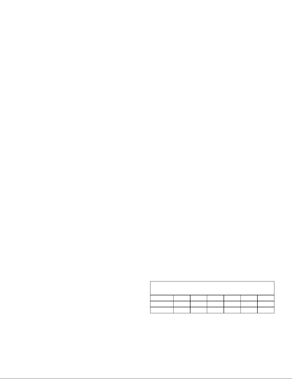
*MES96 MINIM UM CLEARANCES
TO COMBU S TI BLE M A TERIA LS (IN C HES)
POSITION* SIDES REAR FRONT BOTTOM FLUE TOP
Upflow 0" 0" 3" C 0" 1"
Horizontal 6" 0" 3" C 0" 6"
C = If pl aced on combustibl e floor, floor MUST be w ood only.
Table 1
6
Page 7
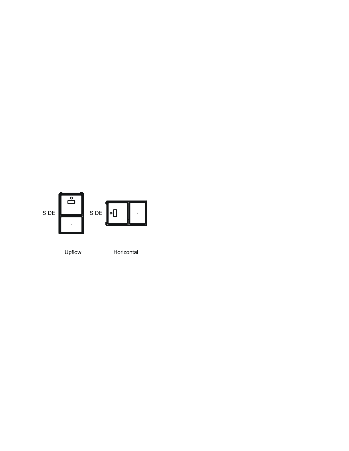
Installations must adhere to the clearances to combustible
materials to which this furnace has been design certified.
The minimum clearance information for this furnace is provided on the unit’ s clearance label. These clearances must
be permanently maintained. Clearances must also accommodate an installation’ s gas, electrical, and drain trap and
drain line connections. If the alternate combustion air intake or vent/flue connections are used additional clearance
must be provided to accommodate these connections. Refer
to Vent/Flue Pipe and Combustion Air Pipe for details.
NOTE: In addition to the required clearances to combustible
materials, a minimum of 24" service clearance must be available in front of the unit.
A furnace installed in a confined space (i.e., a closet or utility
room) must have two ventilation openings with a total minimum
free area of 0.25 square inches per 1,000 BTU/hr of furnace
input rating. Refer to Specification Sheet applicable to your model
for minimum clearances to combustible surfaces. One of the
ventilation openings must be within 12" of the top; the other
opening must be within 12" of the bottom of the confined space.
In a typical construction, the clearance between the door and
door frame is usually adequate to satisfy this ventilation requirement.
TOP
TOP
4. Close fireplace dampers.
5. T urn on clothes dryers and any appliance not connected
to the venting system. Turn on any exhaust fans, such
as range hoods and bathroom exhausts, so they shall
operate at maximum speed. Do not operate a summer
exhaust fan.
6. Follow the lighting instructions. Place the appliance
being inspected in operation. Adjust thermostat so appliance shall operate continuously .
7. If improper venting is observed during any of the above
tests, the venting system must be corrected in accordance with the National Fuel Gas Code ANSI Z223.1/
NFPA 54.
8. After it has been determined that each appliance connected to the venting system properly vents when tested
as outlined above, return doors, windows, exhaust
fans, fireplace dampers and any other gas burning appliance to their previous conditions of use.
If resizing is required on any portion of the venting system, use
the appropriate table in Appendix G in the latest edition of the
National Fuel Gas Code ANSI Z223.1 Installation Codes.
THERMOSTAT LOCATION
BOTTOM
BOTTOM
Figure 1
EXISTING FURNACE REMOVAL
The following vent testing procedure is reproduced from the
American National Standard/National Standard of Canada for
Gas-Fired Central F urnaces ANSI Z21.47, CSA-2.3 latest edition
Section 1.23.1.
The following steps shall be followed with each appliance
connected to the venting system placed in operation, while
any other appliances connected to the venting system are
not in operation:
1. Seal any unused openings in the venting system.
2. Inspect the venting system for proper size and horizontal pitch, as required by the National Fuel Gas Code,
ANSI Z223.1 instructions. Determine that there is no
blockage or restriction, leakage, corrosion and other
deficiencies which could cause an unsafe condition.
The thermostat should be placed approximately five feet from
the floor on a vibration-free, inside wall in an area having good
air circulation. Do not install the thermostat where it may be
influenced by any of the following:
• Drafts, or dead spots behind doors, in corners, or under
cabinets.
• Hot or cold air from registers.
• Radiant heat from the sun.
• Light fixtures or other appliances.
• Radiant heat from a fireplace.
• Concealed hot or cold water pipes, or chimneys.
• Unconditioned areas behind the thermostat, such as
an outside wall.
Consult the instructions packaged with the thermostat for
mounting instructions and further precautions.
3. As far as practical, close all building doors and windows and all doors between the space in which the
appliance(s) connected to the venting system are located and other spaces of the building.
7
Page 8
C
OMBUSTION
TO
AVOID PROPERTY DAMAGE, PERSONAL INJUR Y OR DEATH
SUFFICIEN T FRESH AIR FOR PROPER COMBUSTIO N AND VENTILATION OF
FLUE GASES MUST BE SUPPLIED
SUPPLIED INTO THE FURNACE AREA
& V
ENTILATION AIR REQUIREMENTS
WARNING
. M
OST HOMES REQUIRE OUTSIDE AIR BE
.
,
Improved construction and additional insulation in buildings have
reduced heat loss by reducing air infiltration and escape around
doors and windows. These changes have helped in reducing
heating/cooling costs but have created a problem supplying
combustion and ventilation air for gas fired and other fuel burning
appliances. Appliances that pull air out of the house (clothes
dryers, exhaust fans, fireplaces, etc.) increase the problem by
starving appliances for air.
House depressurization can cause back drafting or improper
combustion of gas-fired appliances, thereby exposing building
occupants to gas combustion products that could include carbon monoxide.
If this furnace is to be installed in the same space with other
gas appliances, such as a water heater, ensure there is an adequate supply of combustion and ventilation air for all appliances. Refer to the latest edition of the National Fuel Gas Code
NFP A 54/ANSI Z223.1 or applicable provisions of the local building codes for determining the combustion air requirements for
the appliances.
Alternate Vent/Flue Location
Figure 2A
Figure 2B
Most homes will require outside air be supplied to the furnace
area by means of ventilation grilles or ducts connecting directly
to the outdoors or spaces open to the outdoors such as attics or
crawl spaces.
I
NST ALLATION POSITIONS
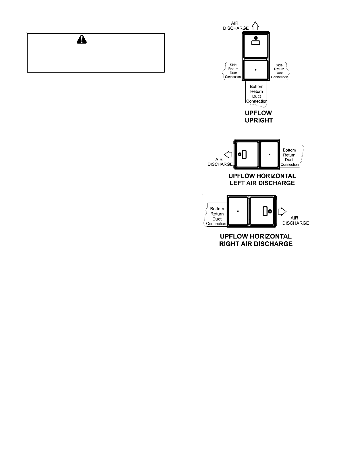
This furnace may be installed in an upright position or horizontal on either the left or right side panel. Do not install this
furnace on its back. For upright upflow furnaces, return air
ductwork may be attached to the side panel(s) and/or basepan.
For horizontal upflow furnaces, return air ductwork must be
attached to the basepan. For both upright or horizontal furnaces, return ductwork must be attached to the basepan (top
end of the blower compartment). NOTE: Ductwork must never
be attached to the back of the furnace. Contact your distributor for proper airflow requirements and number of required
ductwork connections. Refer to “R ecommended Installation Positions” figure for appropriate installation positions, ductwork
connections, and resulting airflow arrangements.
Figure 2C
Recommended Installation Positions
H
ORIZONT AL APPLICA TIONS
& C
ONSIDERA TIONS
When installing a furnace horizontally , additional consideration
must be given to the following:
FURNACE SUSPENSION
If suspending the furnace from rafters or joists, use 3/8" threaded
rod and 2"x2"x1/8" angle iron as shown in the following diagram.
The length of rod will depend on the application and the clearances necessary .
If the furnace is installed in a crawl space it must be suspended
from the floor joist or supported by a concrete pad. Never install
the furnace on the ground or allow it to be exposed to water .
8
Page 9
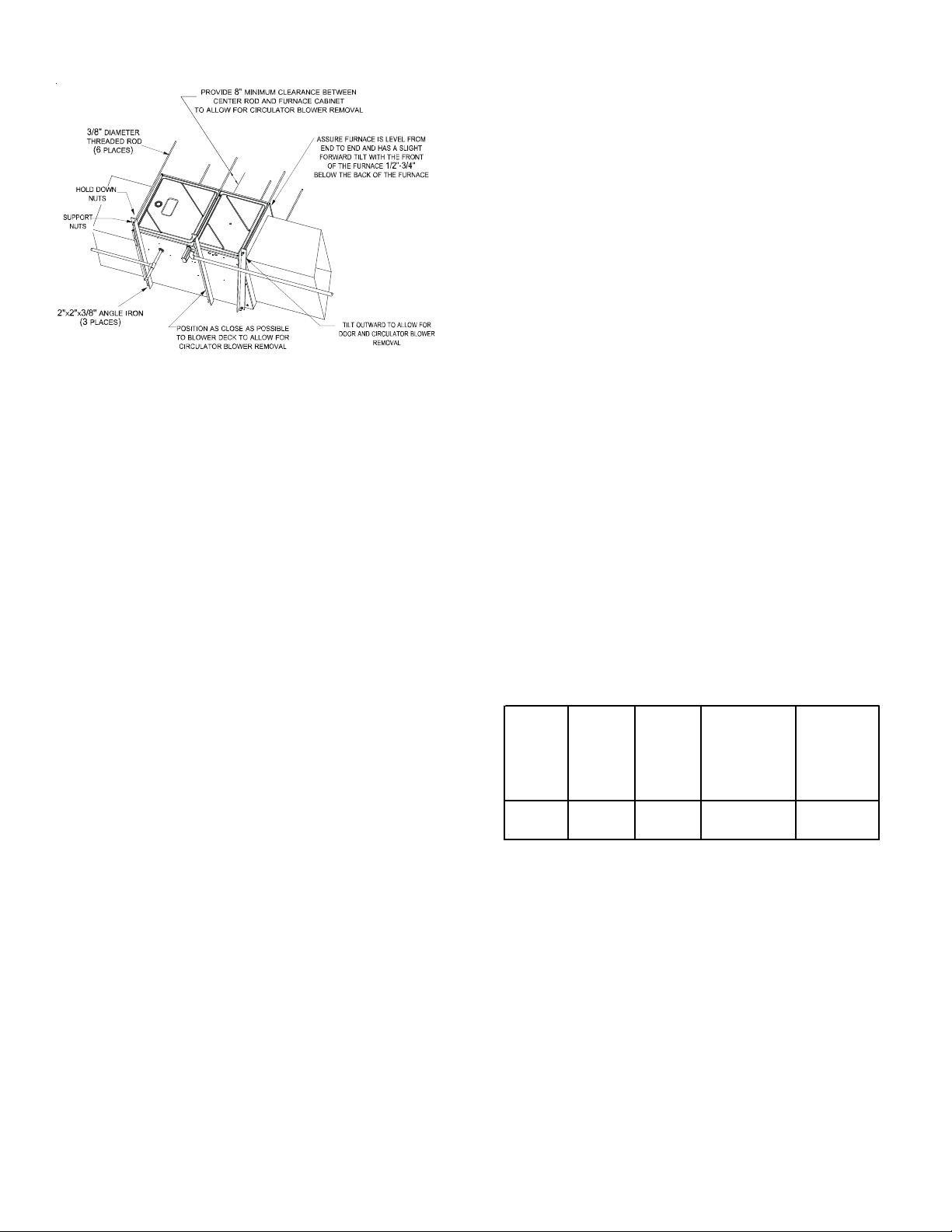
Figure 3
FRONT COVER PRESSURE SWITCH TUBE LOCATION
When a furnace is installed horizontally with left side down,
the front cover pressure switch tube must be re-located to
the lower port of the collector box cover .
1. Remove tube from front cover pressure switch and
collector box cover .
2. Remove rubber plug from bottom collector box port
and install on top collector box port.
3. Locate 24” x 1/4” tube in bag assembly.
4. Install one end on front cover pressure switch.
5. Route tube to lower port on collector box cover and
cut off excess tubing.
ALTERNATE VENT/FLUE AND COMBUSTION AIR CONNECTONS
In horizontial installations provisions for alternate flue and
combustion air piping are available for upflow furnaces with
left discharge. This configuration allows the flue and combustion air piping to be run vertically through the side of the
furnace. Refer to the “R ecommended Installation Positions”
figure for further detail. The standard piping connections
may also be used in these positions. Refer to Vent/Flue Pipe
and Combustion Air Pipe for details concerning the conversion to the alternate vent/flue and combustion air connections.
When using the horizontal alternate vent configuration, you
must use the RF000142 vent drain kit. See Figure 9.
ALTERNATE ELECTRICAL AND GAS LINE CONNECTIONS
This furnace has provisions allowing for electrical and gas line
connections through either side panel. In horizontal applications
the connections can be made either through the “top” or “bottom” of the furnace.
DRAIN PAN
A drain pan must be provided if the furnace is installed above a
conditioned area. The drain pan must cover the entire area
under the furnace (and air conditioning coil if applicable).
FREEZE PROTECTION
Refer to Horizontal Applications and Conditions - Drain Trap and
Lines.
H
IGH ALTITUDE INSTALLATION
DRAIN T RAP AND LINES
In horizontal applications the condensate drain trap is secured to
the furnace side panel, suspending it below the furnace. A minimum clearance of 5.5” below the furnace must be provided for
the drain trap. Additionally, the appropriate downward piping
slope must be maintained from the drain trap to the drain location. Refer to Condensate Drain Trap and Lines for further de-
tails. If the drain trap and drain line will be exposed to temperatures near or below freezing, adequate measures must be taken
to prevent condensate from freezing.
LEVELING
Leveling ensures proper condensate drainage from the heat exchanger. For proper flue pipe drainage, the furnace must be
level lengthwise from end to end. The furnace should have a
slight tilt from back to front with the access doors downhill
from the back panel approximately 1/2" to 3/4". The slight tilt
allows the heat exchanger condensate, generated in the
recuperator coil, to flow forward to the recuperator coil frontcover .
High Altitude Insallation Unit can be installed from 0-4500 ft
only . See table 2.
Gas Al titude Kit
Natural 0-4500' None 3.0" WC None
Table 2
V
ENT/FLUE PIPE
This manual will refer to the pipe that discharges products
of combustion to the outdoors as the “vent” pipe or “flue”
pipe. The pipe that supplies air for combustion to the furnace will be referred to as the “intake” pipe or “combustion
air” pipe. A condensing gas furnace achieves its high level of
efficiency by extracting almost all of the heat from the products
of combustion and cooling them to the point where condensation
takes place. Because of the relatively low flue gas temperature
and water condensation requirements, PVC or ABS pipe is typically used as venting and intake pipe materials.
& C
OMBUSTION AIR PIPE
Manifold
Pressure
Pressure
Switch
Change
9
Page 10
®
In addition to PVC and ABS pipe and fittings, Innoflue
by
Centrotherm Eco Systems and PolyP ro® by M&G Duravent are
also approved vent and combustion air materials for installations in the U.S.A. Manufacturers Installation instructions
for these products must be followed. These products have
specific instructions for installing, joining and terminating.
Do not mix materials or components of onemanufacturer with
materials or components of another manufacturer .
All furnaces are manufactured with 2" vent/intake pipe and
connectors. For furnaces requiring installation of 3" pipe,
the transition from 2" to 3" should be done as close to the
furnace as practically possible, and only in the vertical sections.
This furnace must not be connected to T ype B, BW, or L vent or
vent connector, and must not be vented into any portion of a
factory built or masonry chimney except when used as a pathway
for PVC as described later in this section. Never common vent
this appliance with another appliance or use a vent which is used
by a solid fuel appliance. Do not use commercially available “no
hub connectors” other than those shipped with this product.
It is the responsibility of the installer to follow the manufacturers’ recommendations and to verify that all vent/flue piping and
connectors are compatible with furnace flue products. Additionally , it is the responsibility of the installer to ensure that all piping
and connections possess adequate structural integrity and support to prevent flue pipe separation, shifting, or sagging during
furnace operation.
WARNING
U
PON COMPLETION OF THE FURNACE INSTALLATION, CAREFULLY
INSPECT THE ENTIRE FLUE SYSTEM BOTH INSIDE AND OUTSIDE OF THE
FURNACE TO ASSURE IT IS PROPERLY SEALED
SYSTEM CAN RESULT IN SERIOUS PERSONAL INJURY OR DEATH DUE TO
EXPOSURE TO FLUE PRODUCTS, INCLUDING CARBO N MONOXIDE
. L
EAKS IN THE FLUE
.
MATERIALS AND JOINING METHODS
2" to 3" nominal diameter PVC Schedule 40 pipe meeting
ASTM D1785, PVC primer meeting ASTM F656, and PVC solvent cement meeting ASTM D2564 specifications must be
used. Fittings must be DWV type fittings meeting ASTM
D2665 and ASTM D3311. Carefully follow the manufacturer’ s
instructions for cutting, cleaning, and solvent cementing of
PVC.
The use of Schedule 40 PVC cellular core DWV meeting ASTM
F891-1 or ABS cellular core (Foam Core) plastic pipe is also
acceptable as a flue/vent and intake pipe material. PVC
primer meeting ASTM F656 and PVC solvent cement meeting
ASTM D2564 specifications must be used. Fittings must be
DWV type fittings meeting ASTM D2665 and ASTM D3311.
Carefully follow the manufactures instructions for cutting,
cleaning and solvent cementing of PVC.
NOTE: Requirement does not apply to the combustion air
pipe.
As an alternative to PVC pipe, primer, solvent cement, and fittings, ABS materials which are in compliance with the following
specifications may be used. 2" to 3" ABS Schedule 40 pipe must
meet ASTM D1527. Solvent cement for ABS to ABS joints must
meet ASTM D2235. The solvent cement for the PVC to ABS transition joint must meet ASTM D3138. Fittings must be DWV type
fittings meeting ASTM D2661 and ASTM D3311. Carefully follow
the manufacturers’ instructions for cutting, cleaning, and solvent cementing PVC and/or ABS.
All 90° elbows must be medium radius (1/4 bend DWV) or long
radius (Long sweep 1/4 bend DWV) types conforming to ASTM
D3311. A medium radius (1/4 bend DWV) elbow measures
3-1/16" minimum from the plane of one opening to the center
line of the other opening for 2" diameter pipe, and 4- 9/16"
minimum for 3" pipe.
WARNING
F
AILURE TO FOLLOW THESE INSTRUCTIONS CAN RESULT IN BODILY
INJURY OR DEATH
GIVEN IN THIS SECTION
. C
AREFULLY READ AND FOLLOW ALL INSTRUCTIONS
.
DUAL CERTIFICATION: NON-DIRECT/DIRECT VENT
This furnace is dual certified and may be installed as a non-direct
vent (single pipe) or direct vent (dual pipe) appliance. A non-
direct vent installation requires only a vent/flue pipe, while a
direct vent installation requires both a vent/flue pipe and a com-
bustion air intake pipe. Refer to the appropriate section for
details concerning piping size, length, number of elbows, furnace connections, and terminations.
WARNING
TO
AVOID BODILY INJURY, FIRE OR EXPLOSION, SOLVENT CEMENTS
MUST BE KEPT AWAY FROM ALL IGNITION SOURCES (I.E
FLAMES, AND EXCESSIVE HEAT) AS THEY ARE COMBUSTIBLE LIQUIDS
VOID BREATHING CEMENT VAPORS OR CONTACT WITH SKIN AND/OR
A
EYES
.
.,
SPARKS, OPEN
.
PROPER VENT/FLUE AND COMBUSTION AIR PIPING PRACTICES
Adhere to these instructions to ensure safe and proper furnace
performance. The length, diameter, and number of elbows of
the vent/flue pipe and combustion air pipe (when applicable)
affects the performance of the furnace and must be carefully
sized. All piping must be installed in accordance with local codes
and these instructions.
10
Page 11
ACCEPTABLE
PREFERRED
Figure 4
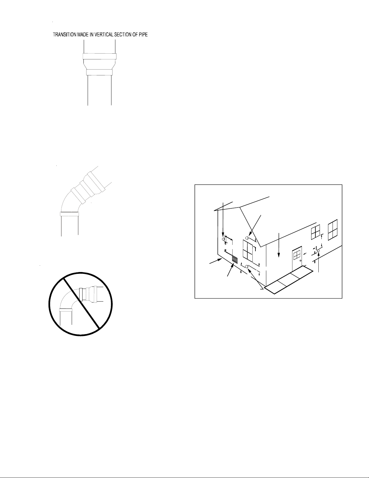
TRANSITION NO LESS
THAN 45 TO HORIZONTAL
°
PLANE TO AVOID CREATING
A WATER TRAP IN VENT
PIPING.
Piping must be adequately secured and supported to prohibit
sagging, joint separation, and/or detachment from the furnace.
Horizontal runs of vent/flue piping must be supported every three
to five feet and must maintain a 1/4" per foot downward slope,
back towards the furnace, to properly return condensate to the
furnace’s drain system. Allowances should be made for minor
expansion and contraction due to temperature variations. For
this reason, particular care must be taken to secure piping when
a long run is followed by a short offset of less than 40".
Precautions should be taken to prevent condensate from freezing inside the vent/flue pipe and/or at the vent/flue pipe termination. All vent/flue piping exposed to freezing temperatures
below 35°F for extended periods of time must be insulated with
1/2" thick closed cell foam. Also all vent/flue piping exposed
outdoors in excess of the terminations shown in this manual (or
in unheated areas) must be insulated with 1/2" thick closed cell
foam. Inspect piping for leaks prior to installing insulation.
TERMINATION LOCATIONS
NOTE: Refer to Location Requirements and Considerations for
combustion air contaminant restrictions.
Non-Direct Vent
&
Direct Vent
Vent/Flue Terminations
Non-Direct Vent
Vent/Flue Termination
No Terminations
Above Walkway
Figure 5
NOT ACCEPTABLE
NO TRANSITION ON
HORIZONTAL PLANE,
THIS CREATES A
WATER T RAP AND
RESTRICTS FLUE
GASES
Figure 6
Some models require the use of 3" pipe. Do not transition
from a 2" to 3" pipe in a horizontal section of pipe as this
may create a water trap.
Grade or Highest
Anticipated
Snow Level
3' min.
Forced Air
Inlet
<10'
12"
12" min.
Direct Vent
Vent/Flue Termination
12" min.
4' min.
4'
min.
12"
min.
Non-Direct Vent
Vent/Flue Termination
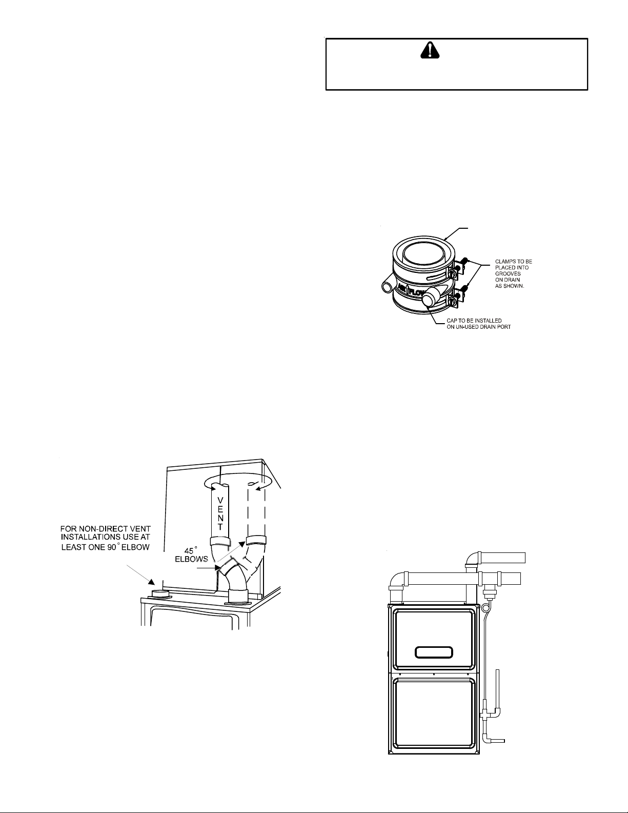
Vent Termination Clearances
Figure 7
The following bullets and diagram describe the restrictions concerning the appropriate location of vent/flue pipe and combustion air intake pipe (when applicable) terminations. Refer to
Non-Direct Vent (Single Pipe) Piping and Direct V ent (Dual Pipe)
Piping located in this section for specific details on termination
construction.
• All terminations (flue and/or intake) must be located
at least 12" above ground level or the anticipated
snow level.
• Vent terminations (non-direct and direct vent) must
terminate at least 3 feet above any forced air inlet
located within 10 feet.
NOTE: This provision does not apply to the combustion
air intake termination of a direct vent application.
• The vent termination of a non-direct vent application
must terminate at least 4 feet below , 4 feet horizontally
from, or 1 foot above any door, window, or gravity air
inlet into any building.
11
Page 12
• The vent termination of a direct vent application must
terminate at least 12" from any opening through which
flue gases may enter a building (door , window , or gravity
air inlet).
• The vent termination of vent pipe run vertically through
a roof must terminate at least 12" above the roof line
(or the anticipated snow level) and be at least 12" from
any vertical wall (including any anticipated snow build
up).
• A vent termination shall not terminate over public
walkways or over an area where condensate or vapor
could create a nuisance or hazard or could be detrimental
to the operation of regulators, relief valves, or other
equipment.
• The combustion air intake termination of a direct vent
application should not terminate in an area which is
frequently dusty or dirty .
STANDARD FURNACE CONNECTIONS
It is the responsibility of the installer to ensure that the piping
connections to the furnace are secure, airtight, and adequately
supported.
WARNING
E
DGES OF SHEET METAL HOLES MAY BE SHARP
PRECAUTION WHEN REMOVING HOLE PLUGS
C
OMBUSTION AIR PIPE
.
. USE
GLOVES AS A
DIRECT VENT I NSTALLATIONS
On upflow units secure the combustion air intake pipe to the air
intake coupling by using a take apart rubber coupling supplied
with the furnace or a plastic coupling. Also, the intake coupling may be inverted to allow the intake pipe to be glued
directly to it. After inverting the coupling, secure it to the
furnace top with screws.
VENT-DRAIN
VENT/FLUE PIPE
The vent pipe outlet is sized to accept 2" pipe. Secure vent/
flue pipe directly into the furnace fitting with the appropriate glue. Alternately, a small section of 2" pipe may be glued
in the furnace socket and a rubber coupling installed to allow
removal for future service. Combustion Air and V ent piping
should be routed in a manner to avoid contact with refrigerant lines, metering devices, condensate drain lines, etc. If
necessary , clearances may be increased by creating an offset using two 45° elbows (Figure 8A).
Figure 8B
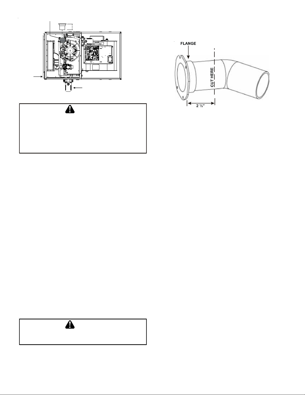
COMBUSTION AIR INT AKE OPTIONS: The RF000142 coupling
(Figure 8B) can be secured directly to the furnace intake
coupling if condensation/rain water is a concern. If the
RF000142 is used on the combustion air inlet, it must be
installed with the arrow pointing up. It should be noted, the
combustion air will actually be moving in a direction opposite of the arrow on the RF000142 coupling. It must have a
field supplied, trapped drain tube free-draining to proper
condensate disposal location. A loop in the drain tube can
serve as a trap. The unused RF000142 drain fitting should
be capped. A tee installed in the intake pipe is also an acceptable method of catching condensation. It must have a
field supplied, trapped drain tube or pipe, free-draining to
proper condensate disposal location. A loop in the drain tube
can serve as a trap.
Exhaust
Combustion Air
Increased Clearance Configuration
Figure 8A
This joint can be rotated on the fitting to establish maximum clearance between refrigerant lines, metering devices,
and condensate drain lines, etc. This joint is the equivalent
of one 90° elbow when considering elbow count.
NOTE: For non-direct vent installations, a minimum of one
90° elbow should be installed on the combustion air intake
coupling to guard against inadvertent blockage. Figure 8A
12
Figure 8C
Page 13
Air Intake
RF000142
Insert flange. Cut 2 ½ ong
2 ½
"
"
Drain Tap
Figure 9
.
RF000142 coupling must have a filed supplied , trapped drain
tube free draining to proper condensate disposal location. A
loop in the drain tube can serve as a trap. The unused
RF000142 drain fitting should be capped.
WARNING
THE
RUBBER ELBOW IS NOT DESIGNED TO SUPPORT A LOAD
RUBBER ELBOW IS MOUNTED EXTERNALLY TO THE FURNACE CABINET
EXTREME CARE MUST BE TAKEN TO ADEQUATELY SUPPORT FIELD
SUPPLIED VENT/FLUE PIPING, AS DAMAGE CAN RESULT IN LEAKS
CAUSING BODILY INJURY OR DEATH DUE TO EXPOSURE TO FLUE GASES
INCLUDING CARBON MONOXIDE
. W
HEN THE
,
-
,
NON-DIRECT VENT INSTALLATIONS
A minimum of one 90° elbow should be installed on the combustion air intake “coupling” to guard against inadvertent blockage. (Figure 8A)
ALTERNATE VENT/FLUE LOCATION
The alternate vent/flue location is the large hole directly in line
with the induced draft blower outlet. T o use the alternate vent/
flue location refer to the following steps and the “Alternate Vent/
Flue Location” Figure 9.
NOTE: In the horizontal left installation position, a means of
condensate collection must be provided to keep vent pipe
condensate from entering the draft inducer housing. If the
vent drain elbow is eliminated from the installation, an
RF000142 kit must be used.
1. Remove the four screws from the vent pipe flange on
top the furnace.
2. Remove the internal elbow and vent pipe
3. Cut 2 1/2" from the flange .
4. Remove plastic plug in line with the inducer outlet
5. Install cut end of the flanged section and connect to
inducer with rubber coupling supplied with furnace.
6. Install screws removed in step 1 securing flange to
cabinet.
Figure 10
ALTERNATE COMBUSTION AIR PROVISION
(Upflow/Horizontal models only)
When using the alternate venting location, either in a horizontal left side down installation or a vertical installation
using down – venting, an alternate combustion air opening
can be used. A locating dimple is located on the right side of
the furnace cabinet. The locating dimple is 1-7/8" measured from the front edge of the cabinet in line with the
knock out. To use the alternate combustion air location:
1. Remove screws and combustion air flange from
cabinet.
2. Insert cabinet plug in unused combustion air hole.
3. Drill a pilot hole at the cabinet dimple (size dictated
by knockout tool used).
4. Use a knockout tool to create a 3" diameter hole
5. Install combustion air flange and secure with screws
removed in step one.
NON-DIRECT VENT (SINGLE PIPE) PIPING
Non-direct vent installations require only a vent/flue pipe. The
vent pipe can be run horizontally with an exit through the side of
the building or run vertically with an exit through the roof of the
building. The vent can also be run through an existing unused
chimney; however, it must extend a minimum of 12" above the
top of the chimney. The space between the vent pipe and the
chimney must be closed with a weather-tight, corrosion-resistant flashing.
Although non-direct vent installations do not require a combus-
tion air intake pipe, a minimum of one 90° elbow should be
attached to the furnace’s combustion air intake if: an upright
CAUTION
BE
SURE NOT TO DAMAGE INTERNAL WIRING OR OTHER COMPONENTS
WHEN REINSTALLING COUPLING AND SCREWS
.
13
Page 14
installation uses the standard intake location, or a horizontal
installation uses the alternate air intake location. This elbow will
guard against inadvertent blockage of the air intake.
VENT/FLUE PIPE LENGTHS AND DIAMETERS
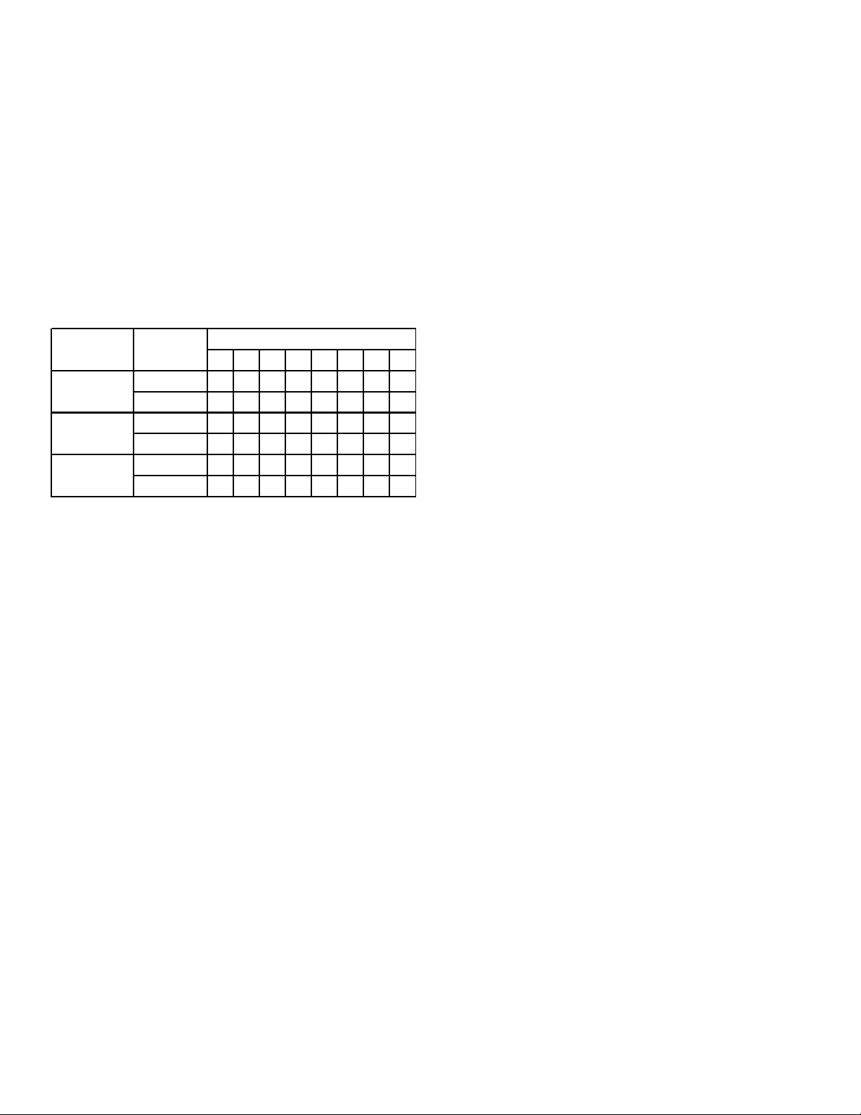
Refer to the Direct and Non-Direct V ent T able 3 for applicable
length, elbows, and pipe diameter for construction of the
vent/flue pipe system of a non-direct vent installation. In
addition to the vent/flue pipe, a single 90° elbow should be
secured to the combustion air intake to prevent inadvertent
blockage. The tee used in the vent/flue termination must be
included when determining the number of elbows in the piping
system.
MAXIMUM ALLOWABLE VENT LENGTH OF VENT/FLUE PIPE &
COMBUSTION AIR PIPE (Ft)
MODEL Pipe Size (in)
*M ES960403BU
*M ES960603BU
*M ES960805C U
12345678
2 9590858075706560
3 103 96 89 82 75 68 61 54
2 9085807570656055
3 158 151 144 137 130 123 1 16 109
2 5550454035302520
3 151 144 137 130 123 116 1 09 102
Table 3
Num ber of Elbows
VENT/FLUE PIPE TERMINATIONS
NOTE: If either a 9 0°or 45 °elbow is used for termination, it
must be pointed downward.
The vent/flue pipe may terminate vertically , as through a roof,
or horizontally , as through an outside wall.
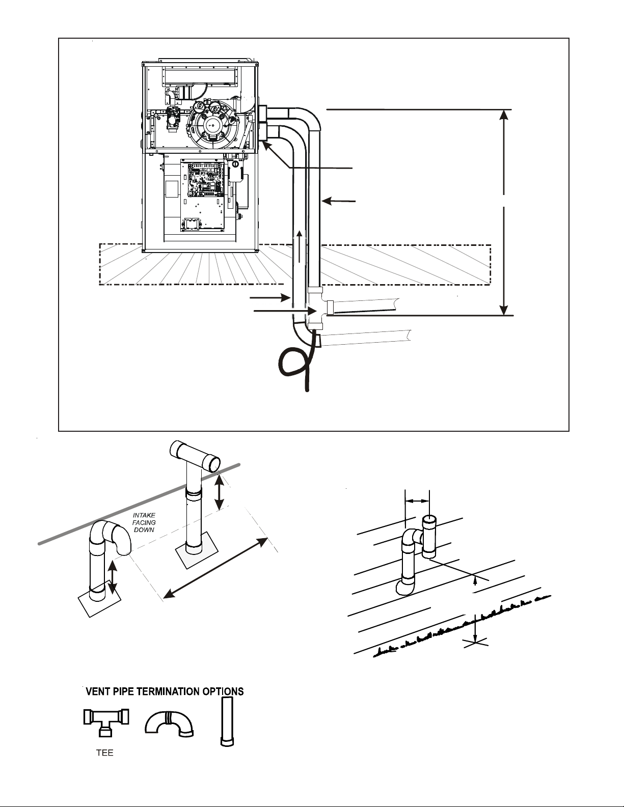
V ertical vent/flue pipe terminations should be as shown in figure
12. Refer to Vent/Flue Pipe and Combustion Air Pipe - T ermina-
tion Locations for details concerning location restrictions. The
penetration of the vent through the roof must be sealed tight
with proper flashing such as is used with a plastic plumbing vent.
Horizontal vent/flue pipe terminations should be as shown in the
following figure. Refer to Vent/Flue Pipe and Combustion Air
Pipe. To secure the pipe passing through the wall and prohibit
damage to piping connections, a coupling should be installed on
either side of the wall and solvent cemented to a length of pipe
connecting the two couplings. The length of pipe should be the
wall thickness plus the depth of the socket fittings to be installed
on the inside and outside of the wall. The wall penetration
should be sealed with silicone caulking material.
NOTE: Terminate both pipes in the same pressure zone
(same side of roof, no major obstacles between pipes,
etc.).
A heat pump thermostat with two stages of heat is required
to properly use a furnace in conjunction with a heat pump.
Refer to the fossil fuel kit installation instructions for additional thermostat requirements.
14
Page 15
DOWN VENTING UPFLOW MODEL FURNACES ONLY
Use alternate vent
& combination air locations
B
COMBUSTION AIR INTAKE
(OPTIONAL)
*Not required for
single pipe installation
Vent Pipe
o
l
F
Combustion Air Pipe
Field Supplied
Drain Te e on Vent Pipe
e
c
a
p
s
l
w
a
r
C
/
t
n
e
em
s
a
All piping and fittings must be joined per material manufacturer’s specifications
to prevent separation and flue gas leaks.
Condensate trapped
to prevent flue gas from escaping
and routed to field supplied
conden s ate disposal
Figure 11
TEE (OPTIONAL)
12” MIN
HEIGHT
DIFFERENCE
6’ MAX.
r
o
Both Pipes Terminated
Outside Structure
1/4” per foot min. slope
12" MIN.
E
N
I
L
F
O
O
R
12” MIN TO ROOF OR
HIGHEST ANTICIPATED
SNOW LEVEL
Figure 12 - Vertical Termination
ELBOWS
Figure 13
X
A
M
”
6
9
STRAIGHT
VENT/FLUE TEE (
TURNED DO WN or
.
N
I
M
”
3
-
.
90° ELBOW TURNED
1 2" MI N. ABOVE
HIGHEST ANTICIPATED
SNOW LEVEL
OPTIONAL)
or
45° EL BOW
DOWN
Horizontal Termination (Single Pipe)
Above Highest Anticipated Snow Level
Figure 14
15
Page 16
DIRECT VENT (DUAL PIPE) PIPING
VENT/FLUE & COMBUSTION AIR PIPE LENGTHS & DIAMETERS
Direct vent installations require both a combustion air intake
and a vent/flue pipe. The pipes may be run horizontally and
exit through the side of the building or run vertically and exit
through the roof of the building. The pipes may be run through
an existing unused chimney; however , they must extend a minimum of 12" above the top of the chimney. The space between
the pipes and the chimney must be closed with a weather tight,
corrosion resistant flashing. Both the combustion air intake and
a vent/flue pipe terminations must be in the same atmospheric
pressure zone. Refer to Vent/Flue and Combustion Air Pipe -
T ermination Locations or Concentric V ent T ermination for specific details on termination construction. For details concerning
connection of pipes to the furnace, refer to the Vent/Flue Pipe
and Combustion Pipe - Standard Furnace Connections or Alter-
nate Furnace Connections.
10”- 24”
6” MAX
4” MIN
Refer to the table 3 on page 14 for applicable length, elbows,
and pipe diameter for construction of the vent/flue and combustion air intake pipe systems of a direct vent (dual pipe)
installation. The number of elbows tabulated represents the
number of elbows and/or tees in each (Vent/Flue & Combustion
Air Intake) pipe. Elbows and/or tees used in the terminations
must be included when determining the number of elbows in
the piping systems.
If the combustion air intake pipe is to be installed above a
finished ceiling or other area where dripping of condensate will
be objectionable, insulation of the combustion air pipe may be
required.
90°
ELBOWS
12" MIN. TO GRADE OR
HIGHEST ANTICIPATED
SNOW LEVEL
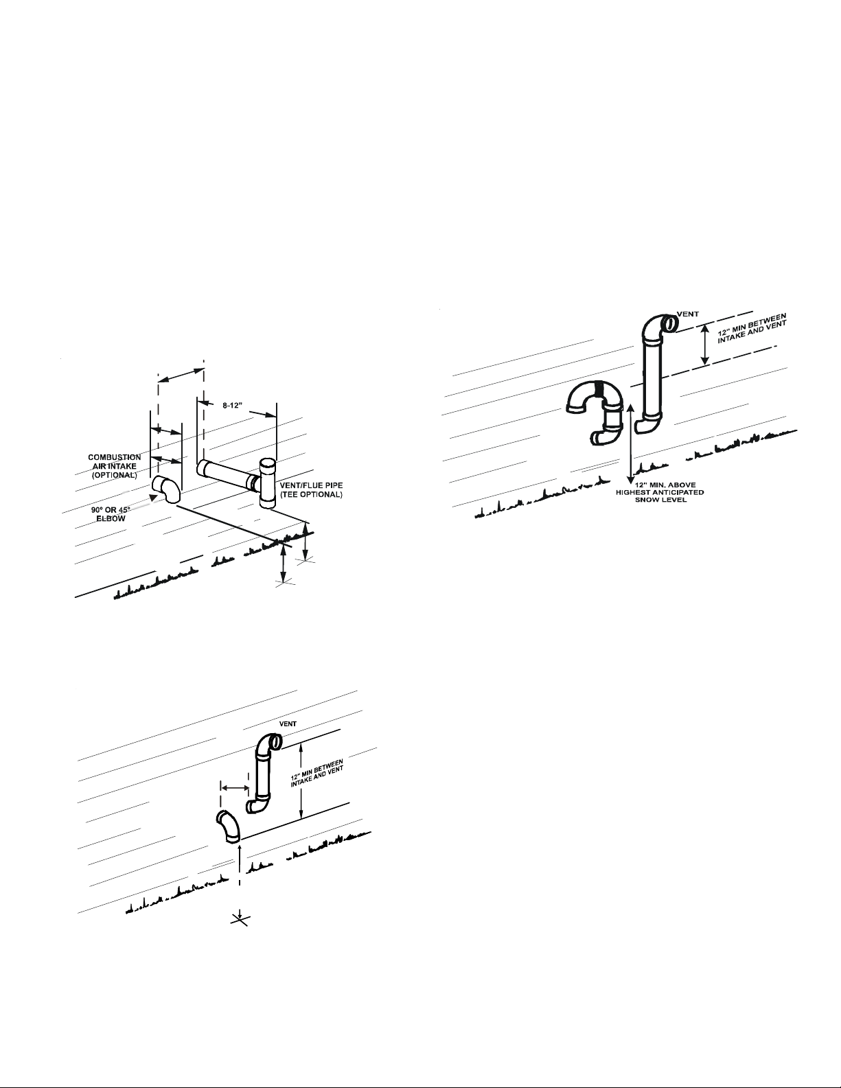
Standard Horizontal Terminations (Dual Pipe)
Figure 15
90°
ELBOWS
3” - 24”
12" MIN. ABOVE
HIGHEST ANTICIPATED
SNOW LEVEL
Combustion Air Intake may also be snorkeled
to obtain 12" min ground clearance.
Alternate Vent Termination Above Anticipated Snow Level
(Dual Pipe)
Figure 17
Use ½" thick closed cell foam insulation such as Armaflex™
or Insultube™ where required.
VENT/FLUE AND COMBUSTION AIR PIPE TERMINATIONS
The vent/flue and combustion air pipes may terminate vertically, as through a roof, or horizontally, as through an outside
wall.
Vertical pipe terminations should be as shown in figure 12. Refer
to Vent/Flue Pipe and Combustion Pipe - Termination Locations
for details concerning location restrictions. The penetrations
through the roof must be sealed tight with proper flashing such
as is used with a plastic plumbing vent.
Vent & Combustion Air Intake Measurements for Standard Horizontal Terminations (Dual Pipe)
Center to center = 10" min / 24" max.
Alternate Horizontal Vent Termination (Dual Pipe)
Figure 16
V ertical separation: 0" - 24"
V ent termination from wall = 8" min/ 12" max.
Combustion air intake from wall = 4" min/6" max.
Vent and intake clearance to ground or anticipated snow
level = 12" min.
16
Page 17
VENT/INTAKE TERMINATIONS FOR INSTALLATION OF MULTIPLE
DIRECT VENT FURNACES
If more than one direct vent furnace is to be installed vertically
through a common roof top, maintain the same minimum clearances between the exhaust vent and air intake terminations of
adjacent units as with the exhaust vent and air intake terminations of a single unit.
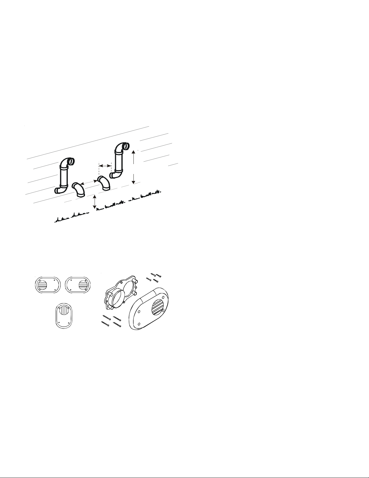
If more than one direct vent furnace is to be installed horizontally through a common side wall, maintain the clearances as in
the following figure. Always terminate all exhaust vent outlets
at the same elevation and always terminate all air intakes at
the same elevation.
10”MIN
24”MAX
12” MIN SEPARATION
3” MIN
12” MIN TO GRADE OR HIGHEST
ANTICIPATED SNOW LEVEL
Termination of Multiple Direct Vent Furnaces
Figure 18
CONCENTRIC VENT TERMINATION
Refer to the directions provided with the Concentric Vent Kit
(DCVK) for installation specifications.
Allowable Installation Orentation
Horizontal Installation
C
ONDENSA TE DRAIN LINES
& D
RAIN TRAP
A condensing gas furnace achieves its high level of efficiency by
extracting heat from the products of combustion to the point
where condensation takes place. The condensate must be collected in the furnace drain trap and routed to an appropriate drain location in compliance with local and national codes.
Follow the bullets listed below when installing the drain system.
Refer to the following sections for specific details concerning
furnace drain trap installation and drain hose hook ups.
• The drain trap supplied with the furnace must be
used.
• The drain trap must be primed at time of
installation.
• The drain line between furnace and drain location
must meet local and nation codes.
• The drain line between furnace and drain location
must maintain a 1/4" per foot downward slope
toward the drain.
• Do not trap the drain line in any other location than
at the drain trap supplied with the furnace.
• If the drain line is routed through an area which may
see temperatures near or below freezing,
precautions must be taken to prevent condensate
from freezing within the drain line.
• If an air conditioning coil is installed with the
furnace, a common drain may be used. An open tee
must be installed in the drain line, near the cooling
coil, to relieve positive air pressure from the coil’s
plenum. This is necessary to prohibit any
interference with the function of the furnace’ s drain
trap.
NOTE: In vertical installations, air conditioning coil condensate may drain into the furnace trap as long as there is a
trap between the coil and the furnace trap and the drain
pipe is not terminating below the water level of the furnace
trap.
Vertical Installation
Side Wall Vent Kit
Figure 19
SIDE WALL VENT KIT
This kit is to be used with 2” or 3” direct vent systems. The
vent kit must terminate outside the structure and may be installed with the intake and exhaust pipes located side-by-side
or with one pipe above the other . These kits are NOT intended
for use with single pipe (non-direct vent) installations.
Refer to the directions furnished with the Side Wall V ent Kit
(p/n 0170K00000S or 0170K00001S) for installation specifications.
17
Page 18
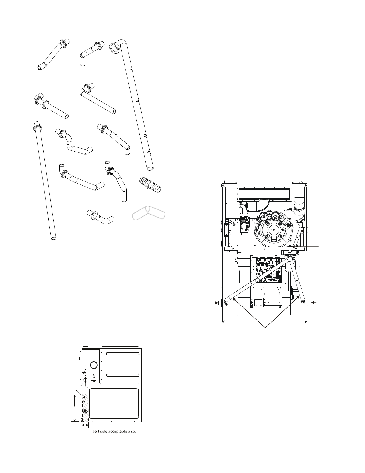
#1
#2
FIELD SUPPLIED DRAIN
Drain the furnace and air conditioning coil if applicable, in
compliance with code requirements. In horizontal installations, a field installed rubber coupling will allow the drain
trap to be removed for cleaning. The drain trap must be
primed before initial furnace start up. When an air conditioning coil drain is connected to the field supplied furnace
drain, it must be vented. An open tee must be installed at a
3
#
height no higher than the bottom of the furnace collector
box to prevent air conditioning condensate from backing up
into the furnace, if the common drain was blocked.
#4
#7
#9
6
#
#5
#11
Figure 20
#8
#10
100 Degree
Elbow
Coupling
NOTE: Drain components shown for information purposes only.
GENERAL DRAIN INFORMATION
UPFLOW MODEL INSTALLED VERTICALLY
The trap and factory installed hoses remain as shipped. The
furnace drain may exit either the right or left side of the
furnace cabinet. Both sides of the cabinet have two .875”
diameter holes which can be used interchangeably for drain
and low voltage wiring purposes. If a higher drain exit is
needed, a .875” diameter hole may be added in the area
shown in Figure 21. Any unused cabinet opening must be
sealed. Do not allow drain hose to sag or trap water.
Hose #1
Hose #2
All furnace models come with a factory installed drain trap.
For vertical installations, the trap will remain in the factory
position. All furnace models installed horizontally require the
trap to be relocated. Many drain hoses have a built–in grommet which will provide a cabinet seal when installed. See
instructions below for your model and installation position.
NOTE: Both sides of the drain trap must be primed prior
to initial furnace start up
Acceptable
area for
drain hole.
12”
3”
Side Cut-Out
Right side shown.
Figure 21
18
45
barb-pipe
adapter
º
Installer selects right or left side drain
and installs this hose accordingly
Figure 22
45
barb-pipe
adapter
º
Page 19
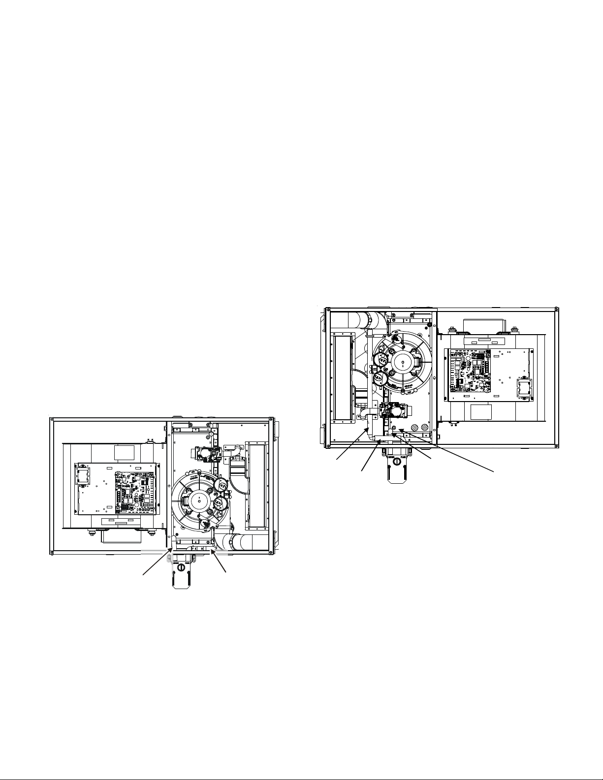
DRAIN EXITING RIGHT SIDE
1. Locate and Install the 45º pipe/hose drain coupling
from the outside of the cabinet (barbed end goes in
the cabinet) through hole in the right side of the cabinet
and secure with two field supplied #8 self-tapping
screws (see Figure 22).
2. Locate the long drain hose #3 and cut at line “A”.
3. Install large end of hose #3 to trap outlet and secure
with 1.25" clamp.
4. Install smaller end of hose #3 on 45º elbow and secure
with 1" clamp.
5. Refer to Field Supplied Drain section for instructions
on field supplied/installed drain on outlet of furnace
trap.
DRAIN EXITING LEFT SIDE
1. Install the 45º pipe/hose drain coupling from the
outside of the cabinet (barbed end goes in the cabinet)
through the hole in the left side of the cabinet and
secure with two field supplied #8 self-tapping screws
(see Figure 22).
2. Locate the long drain hose #3 and cut at “B” line for a
17.5" cabinet; cut at line “C” for a 21" cabinet; do not
cut for a “D” width cabinet.
3. Install large end of hose #3 to trap outlet and secure
with 1.25" clamp.
4. Install smaller end of hose #3 on 45º elbow and secure
with 1" clamp.
5. Refer to Field Supplied Drain section for instructions
on field supplied/installed drain on outlet of furnace
trap.
3. Remove the trap and two hoses from the blower deck
4. Remove the two plugs from the right side of the cabinet
and install them in the blower deck.
5. Draining the Vent Elbow: Locate hose #2 (factory
installed) and cut 1" away from the 45º bend, discard
the 45º section. Insert hose #2 from outside the cabinet
through the cabinet drain hole nearest the top, secure
it to the barbed fitting in the elbow with a red clamp.
6. Draining the Collector Box: Install the non-grommet
end of hose #11 from outside the cabinet in the bottom
drain hole. Install on collector box and secure with a
silver clamp.
7. Use two silver clamps and secure the hoses to drain
trap. The trap outlet faces the front of the furnace.
Secure the trap to the cabinet using two screws
removed in step 2 by inserting the two screws through
the large set of holes in the top mounting tabs of the
trap into the two predrilled holes in the side of the
cabinet.
8. Refer to Field Supplied Drain section for instructions
on field supplied/installed drain on outlet of furnace
trap.
Hose #11
Figure 23
Hose #2
UPFLOW MODEL INSTALLED HORIZONTALLY WITH RIGHT SIDE
DOWN
Minimum 5 ½" clearance is required for the drain trap beneath the furnace.
1. Remove the clamps from both ends of the drain hoses.
2. Remove the two screws holding the drain trap to the
blower deck.
Hose #6
Hose #11
Hose #5
Figure 24
Front Cover
Pressure Switch
Tube Locati on
UPFLOW MODEL INSTALLED HORIZONTALLY WITH LEFT SIDE
DOWN
Minimum 5 ½" clearance is required for the drain trap beneath the furnace.
*See Front Cover Pressure Switch Tube Location on Figure
24.
1. Remove the clamps from the two drain tubes on the trap.
2. Remove the two screws holding the drain trap to the
blower deck.
3. Remove the trap and hoses from the blower deck.
4. Remove the two plugs from the left side of the cabinet
and install them in the blower deck.
5. Draining the Vent Elbow: Locate hose #6. Measuring
from the non-grommet end; cut off and discard 1 ½"
for a “D” width cabinet, 5” for a “C” width cabinet, 8
½" for a “B” width cabinet.
19
Page 20
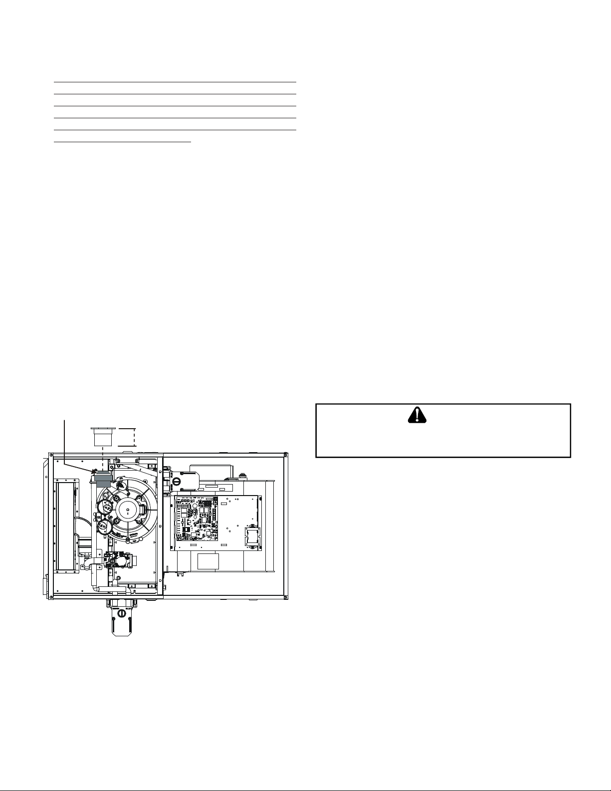
6. Remove the rubber plug from vent – drain elbow side
port. Place hose #6 on the vent – drain elbow side port
and secure with a silver clamp .
7.
Unused vent-drain elbow drip leg port must be sealed
to prevent flue gases from escaping. Insert the rubber
plug removed in step 6 into the unused elbow drain
port. Inserting a blunt tool such as a 3/16’ ’ Allen wrench
into the center of the rubber plug will stretch the plug
and allow complete insertion.
8. Locate hose #5 and cut 3" from the non-grommet end.
Discard the section without the grommet.
9. Insert the cut end of tube #5 through the lower cabinet
drain hole.
10.Connect hose #6 & hose #5 using 100º elbow and secure
with two red clamps
11.Draining the Collector Box: Remove cap from left side
collector box drain port (bottom in horizontal left position)
and install it on right side (top) collector box drain port.
12.Install the non-grommet end of hose #11 from outside
the cabinet in the upper drain hole. Install on collector
box and secure with a silver clamp.
13.Use two silver clamps and secure the hoses to drain trap.
The trap outlet faces the front of the furnace. Secure
the trap to the cabinet using two screws removed in
step 2 by inserting the two screws through the large set
of holes in the top mounting tabs of the trap into the
two pre-drilled holes in the side of the cabinet.
14.Refer to Field Supplied Drain section for instructions on
field supplied/installed drain on outlet of furnace trap.
1. Draining the RF000142 Coupling: Locate hose #2
(factory installed). Cut off and discard the 45° radius
end.
2. Install 90°radius end of hose #2 on RF000142 drain
outlet and secure with a red clamp.
3. Insert coupling in hose #2 and secure with a red clamp.
4. Locate hose #5 and cut 3” from the non-grommet end.
Discard the section without the grommet.
5. Insert the cut end of tube #5 through the lower cabinet
drain hole.
6. Insert 100° elbow in the cut end of hose #5.
7. Locate hose #6. Using red clamps, connect between
the coupling and 100° elbow , cutting off excess tubing.
8. Draining the Collector Box: Remove cap from left side
collector box drain port (bottom in horizontal left
position) and install it on right side (top) collector box
drain port and secure with a red clamp.
9. Install the non-grommet end of hose #11 from outside
the cabinet in the upper drain hole. Install on collector
box and secure with a silver clamp.
10. Use two silver clamps and secure the hoses to drain
trap. The trap outlet faces the front of the furnace.
Secure the trap to the cabinet using two screws
removed in step 2 by inserting the two screws through
the large set of holes in the top mounting tabs of the
trap.
E
LECTRICAL CONNECTIONS
RF000142
Insert flange. Cut 2 ½” long
.
2 ½”
Figure 25
UPFLOW MODEL INSTALLED HORIZONTALLY WITH LEFT SIDE
DOWN - ALTERNATE
*See Front Cover Pressure Switch T ube Location on Figure
24.
WARNING
E
DGES OF SHEET METAL HOLES MAY BE SHARP
PRECAUTION WHEN REMOVING HOLE PLUGS
. USE
.
GLOVES AS A
WIRING HARNESS
The wiring harness is an integral part of this furnace. Wires
are color coded for identification purposes. Refer to the wiring
diagram for wire routings. If any of the original wire as supplied with the furnace must be replaced, it must be replaced
with wiring material having a temperature rating of at least
e
105°C. Any replacement wiring must be a copper conductor.
115 VOLT LINE CONNECTIONS
Before proceeding with electrical connections, ensure that the
supply voltage, frequency , and phase correspond to that specified on the unit rating plate. Power supply to the furnace must
be NEC Class 1, and must comply with all applicable codes. The
furnace must be electrically grounded in accordance with local
codes or, in their absence, with the latest edition of The National Electric Code, ANSI NFPA 70.
Use a separate fused branch electrical circuit containing properly sized wire, and fuse or circuit breaker . The fuse or circuit
breaker must be sized in accordance with the maximum
overcurrent protection specified on the unit rating plate. An
electrical disconnect must be provided at the furnace location.
20
Page 21
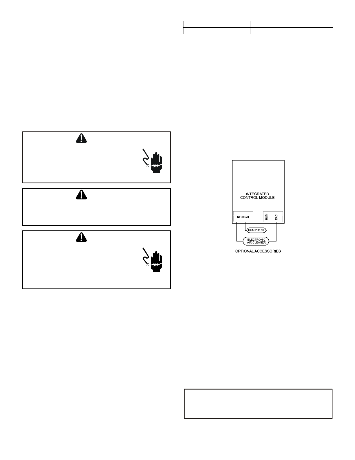
Connect hot, neutral, and ground wires as shown in the wiring
diagram located on the unit’s blower door. For direct vent applications, the cabinet opening to the junction box must be
sealed air tight using either an UL approved bushing such as
Heyco Liquid Tight or by applying non-reactive UL approved
sealant to bushing.
Line polarity must be observed when making field connections.
Line voltage connections can be made through either the right
or left side panel. The furnace is shipped configured for a left
side electrical connection with the junction box located inside
the burner compartment. T o make electrical connections through
the opposite side of the furnace, the junction box must be
relocated to the other side of the burner compartment prior to
making electrical connections. To relocate the junction box,
follow the steps shown in the Junction Box Relocation section.
WARNING
Humidifier 1.0 Amp m aximum at 120 V AC
Elec tronic Air Cleaner 1.0 Amp maximum at 120 VAC
Table 4
If it is necessary for the installer to supply additional line voltage
wiring to the inside of the furnace, the wiring must conform to
all local codes, and have a minimum temperature rating of 105°C.
All line voltage wire splices must be made inside the furnace
junction box.
The integrated control module single humidifier terminal (HUM)
is energized with 115 volts whenever the induced draft blower is
ene rg ize d. This terminal can also be used to provide 115 volt
power to a humidifier transformer. The remaining primary
transformer wire would be connected to the Line N on the
control board. The integrated control module electronic air
cleaner terminals (EAC) are energized with 115 volts whenever
the circulator blower is energized.
HIGH VOLTAGE !
TO
AVOID PERSONAL INJURY OR DEATH DUE TO
ELECTRICAL SHOCK, DISCONNECT ELECTRICAL POWER
BEFORE SERVICING OR CHANGING ANY ELECTRICAL
WIRING
.
CAUTION
L
ABEL ALL WIRES PRIOR TO DISCONNECTION WHEN SERVICING
CONTROLS
OPERATION
. W
IRING ERRORS CAN CAUSE IMPROPER AND DANGEROUS
. V
ERIFY PROPER OPERATION AFTER SERVICING
.
WARNING
HIGH VOLTAGE !
TO
AVOID THE RISK OF INJURY, ELECTRICAL SHOCK OR
DEATH, THE FURNACE MUST BE ELECTRICALLY
GROUNDED IN ACCORDANCE WITH LOCAL CODES OR IN
THEIR ABSENCE, WITH THE LATEST EDITION OF THE
ATIONAL ELECTRIC CODE
N
.
115 VOLT LINE VOLTAGE CONNECTION OF ACCESSORIES
(HUMIDIFIER AND ELECTRONIC AIR CLEANER)
The furnace integrated control module is equipped with line voltage accessory terminals for controlling power to an optional fieldsupplied humidifier and/or electronic air cleaner .
The accessory load specifications are as follows:
T urn OFF power to the furnace before installing any accessories.
Follow the humidifier and/or air cleaner manufacturers’ instructions for locating, mounting, grounding, and controlling these
accessories. Accessory wiring connections are to be made through
the 1/4" quick connect terminals provided on the furnace integrated control module. The humidifier and electronic air cleaner
hot terminals are identified as HUM and EAC. The humidifier
and electronic air cleaner neutral terminals are identified as NEUTRAL. All field wiring must conform to applicable codes.
NOTE: Wire routing must not to interfere with circulator blower
operation, filter removal, or routine maintenance.
Figure 26
JUNCTION BOX RELOCATION
Line voltage connections can be made through either the
right or left side panel. The furnace is shipped configured for a left side electrical connection. To make electrical connections through the opposite side of the furnace, the junction box must be relocated to the left side
prior to making electrical connections. To relocate the
junction box, perform the following steps.
1. Remove the burner compartment door .
2. Remove and save the two screws securing the junction
box to the side panel.
3. Relocate junction box and associated plugs and grommets
to opposite side panel. Secure with screws removed in
step 2.
IMPORTANT NOTE
W
IRE ROUTING MUST NOT INTERFERE WITH CIRCULATOR BLOWER
OPERATION, FILTER REMOVAL OR ROUTINE MAINTENANCE
.
21
Page 22
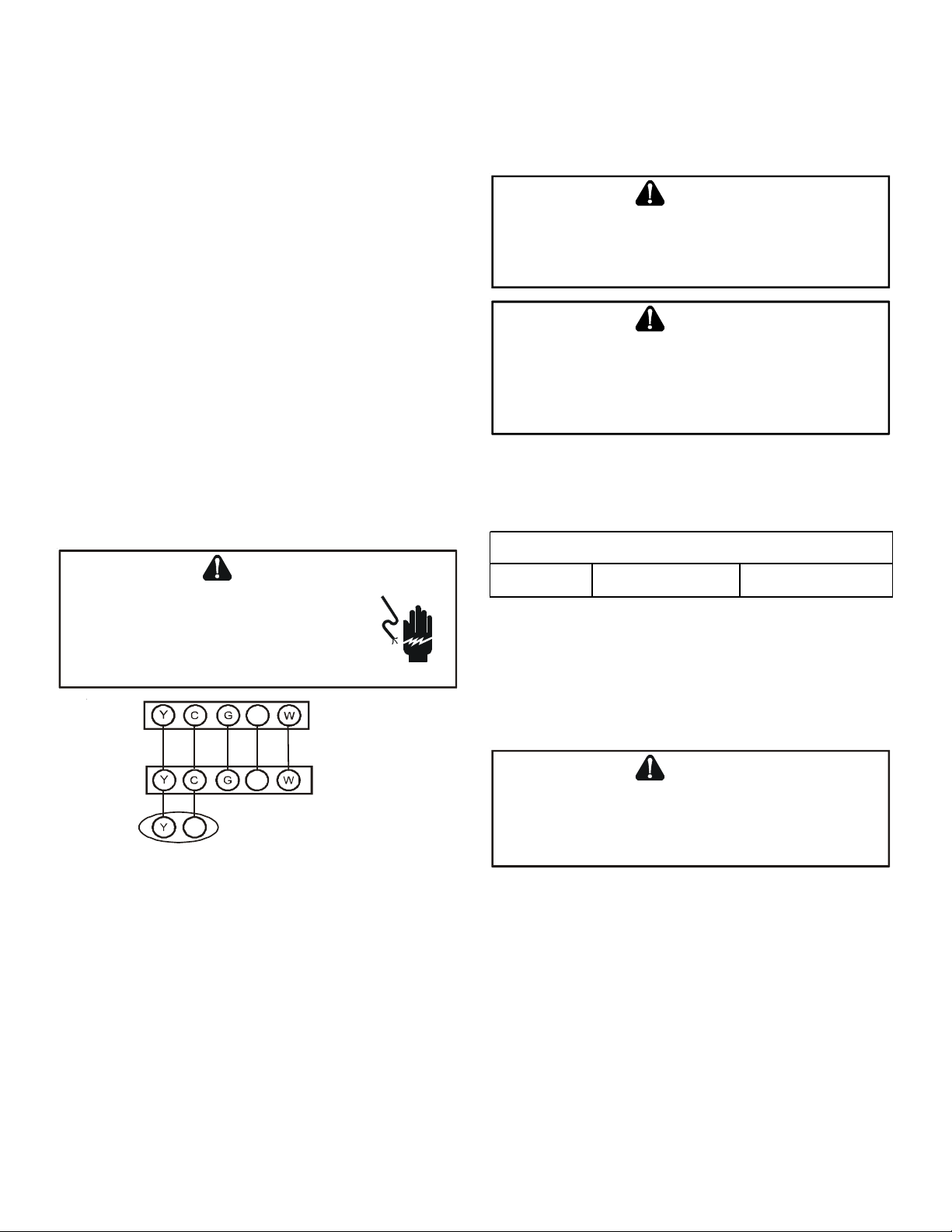
To ensure proper unit grounding, the ground wire should run
from the furnace ground screw located inside the furnace junction box all the way back to the electrical panel. NOTE: Do not
use gas piping as an electrical ground. To confirm proper unit
grounding, turn off the electrical power and perform the following check.
1. Measure resistance between the neutral (white) connection
and any unpainted surface.
2. Resistance should measure 10 ohms or less.
This furnace is equipped with a blower door interlock switch
which interrupts unit voltage when the blower door is opened
for servicing. Do not defeat this switch.
Strictly follow the wiring guidelines in the fossil fuel kit installation instructions. All furnace connections must be made to the
furnace integrated control module and the “FURNACE” terminal strip on the fossil fuel control board.
GAS S
UPPLY AND PIPING
CAUTION
TO
PREVENT UNRELIABLE OPERATION OR EQUIPMENT DAMAGE, THE
GAS MANIFOLD PRESSURE MUST BE AS SPECIFIED ON THE UNIT RATING
PLATE
. O
NLY MINOR ADJUSTMENTS SHOULD BE MADE BY ADJUSTING
THE GAS VALVE PRESSURE REGULATOR
.
24 VOLT THERMOSTAT WIRING
NOTE: Wire routing must not interfere with circulator blower
operation, filter removal or routine maintenance.
Low voltage connections can be made through either the right or
left side panel. Thermostat wiring entrance holes are located in
the blower compartment. The following figure shows connections for a “heat/cool system”.
This furnace is equipped with a 40 VA transformer to facilitate
use with most cooling equipment. Consult the wiring diagram,
located on the blower compartment door, for further details of
115 Volt and 24 V olt wiring.
WARNING
HIGH VOLTAGE !
TO
AVOID PERSONAL INJURY OR DEATH DUE TO
ELECTRICAL SHOCK, DISCONNECT ELECTRICAL POWER
BEFORE SERVICING OR CHANGING ANY ELECTRICAL
WIRING
.
R
Room
Thermostat
R
C
Remote Condensing Unit
(Single-Stage Cooling)
Figure 27
Furnace Integrated
Control Module
WARNING
P
OSSIBLE PROPERTY DAMAGE, PERSONAL INJURY OR DEATH MAY
OCCUR IF THE CORRECT CONVERSION KITS ARE NOT INSTALLED
APPROPRIATE KITS MUST BE APPLIED TO ENSURE SAFE AND PROPER
FURNACE OPERATION
QUALIFIED INSTALLER OR SERVICE AGENCY
. ALL
CONVERSIONS MUST BE PERFORMED BY A
.
. THE
The furnace rating plate includes the approved furnace gas
input rating and gas types. The furnace must be equipped to
operate on the type of gas applied. This includes any conversion kits required for alternate fuels and/or high altitude.
INLET GAS SUPPLY PRESSURE
Natural Gas Minimum: 4.5" W.C. Maximum: 10.0" W.C.
Table 5
Inlet gas supply pressures must be maintained within the ranges
specified in the table 5. The supply pressure must be constant
and available with all other household gas fired appliances operating. The minimum gas supply pressure must be maintained to prevent unreliable ignition. The maximum must not
be exceeded to prevent unit overfiring.
WARNING
TO
AVOID POSSIBLE UNSATISFACTORY OPERATION OF EQUIPMENT
DAMAGE DUE TO UNDERFIRING OR EQUIPMENT, USE THE PROPER SIZE
OF NATURAL GAS PIPING NEEDED WHEN RUNNING PIPE FROM THE
METER/TANK TO THE FURNACE
.
HIGH ALTITUDE DERATE
SINGLE-STAGE HEATING THERMOSTAT APPLICATION
A single-stage thermostat with only one heating stage is
needed to control this furnace.
FOSSIL FUEL APPLICATIONS
This furnace can be used in conjunction with a heat pump in a
fossil fuel application. A fossil fuel application refers to a combined gas furnace and heat pump installation which uses an outdoor temperature sensor to determine the most cost efficient
means of heating (heat pump or gas furnace).
The furnace shall be installed within 0-4500’ of altitude.
GAS VALVE
This unit is equipped with a 24 volt gas valve controlled during
furnace operation by the integrated control module. As shipped,
the valve is configured for natural gas. T aps for measuring the
gas supply pressure and manifold pressure are provided on the
valve.
The gas valve has a manual ON/OFF control located on the
valve itself. This control may be set only to the “ON” or “OFF”
22
Page 23
position. Refer to the lighting instructions label or Startup Procedure & Adjustment for use of this control during start up and
shut down periods.
GAS PIPING CONNECTIONS
WARNING
TO
AVOID POSSIBLE UNSATISFACTORY OPERATION OF EQUIPMENT
DAMAGE DUE TO UNDERFIRING OR EQUIPMENT, USE THE PROPER SIZE
OF NATURAL GAS PIPING NEEDED WHEN RUNNING PIPE FROM THE
METER/TANK TO THE FURNACE
.
When sizing gas lines, be sure to include all appliances which
will operate simultaneously . The gas piping supplying the furnace must be properly sized based on the gas flow required,
specific gravity of the gas, and length of the run. The gas line
installation must comply with local codes, or in their absence,
with the latest edition of the National Fuel Gas Code, NFP A 54/
ANSI Z223.1
T o connect the furnace to the building’ s gas piping, the installer
must supply a ground joint union, drip leg, manual shutoff valve,
and line and fittings to connect to gas valve. In some cases, the
installer may also need to supply a transition piece from 1/2"
pipe to a larger pipe size.
The following stipulations apply when connecting gas piping. Refer to Gas Piping Connections figures 28 and 29 for typical gas
line connections to the furnace.
• Gas piping must be supported external to the furnace
cabinet so that the weight of the gas line does not
distort the burner rack, manifold or gas valve.
• Use black iron or steel pipe and fittings for building piping.
Where possible, use new pipe that is properly chamfered,
reamed, and free of burrs and chips. If old pipe is used,
be sure it is clean and free of rust, scale, burrs, chips,
and old pipe joint compound.
• Use pipe joint compound on male threads ONL Y. Always
use pipe joint compound (pipe dope) that is APPROVED
FOR ALL GASSES. DO NOT apply compound to the first
two threads.
• Use ground joint unions.
• Install a drip leg to trap dirt and moisture before it can
enter the gas valve. The drip leg must be a minimum of
3" long.
• Install a 1/8" NPT pipe plug fitting, accessible for test
gauge connection, immediately upstream of the gas supply
connection to the furnace.
• Always use a back-up wrench when making the connection
to the gas valve to keep it from turning. The orientation
of the gas valve on the manifold must be maintained as
shipped from the factory. Maximum torque for the gas
valve connection is 375 in-lbs; excessive over-tightening
may damage the gas valve.
• Install a manual shutoff valve between the gas meter and
unit within six feet of the unit. If a union is installed, the
union must be downstream of the manual shutoff valve,
between the shutoff valve and the furnace.
• Tighten all joints securely .
Natural Gas Capacity of Pipe
Length of Nominal Black Pipe Size
Pipe in Feet 1/2" 3/4" 1" 1 1/4" 1 1/2"
10 132 278 520 1050 1600
20 92 190 350 730 1100
30 73 152 285 590 980
40 63 130 245 500 760
50 56 115 215 440 670
60 50 105 195 400 610
70 46 96 180 370 560
80 43 90 170 350 530
90 40 84 160 320 490
100 38 79 150 305 460
(Pressure 0.5 psig or less and pres sure drop of 0.3" W.C.; Based on
0.60 Specific Gravity Gas)
BTUH Furnace Input
CFH =
Heating Value of Gas ( BTU/Cubic Foot)
In Cubic Feet of Gas Per Hour ( CFH)
Table 6
• Connection method must be in compliance with all local
and national codes. US: National Fuel Gas Code (NFGC)
NFPA 54-2012/ANSI Z223.1-2012 and the Installation
Standards, Warm Air Heating and Air Conditioning
Systems ANSI/NFP A 90B.
Connect the furnace to the building piping by one of the
following methods:
– Rigid metallic pipe and fittings.
– Semi-rigid metallic tubing and metallic fittings.
Aluminum alloy tubing must not be used in exterior
locations. In order to seal the grommet cabinet
penetration, rigid pipe must be used to reach the
outside of the cabinet. A semi-rigid connector to the
gas piping may be used from there.
• Use listed gas appliance connectors in accordance with
their instructions. Connectors must be fully in the same
room as the furnace.
• Protect connectors and semirigid tubing against physical
and thermal damage when installed. Ensure aluminumalloy tubing and connectors are coated to protect against
external corrosion when in contact with masonry , plaster ,
or insulation, or subjected to repeated wetting by liquids
such as water (except rain water), detergents, or sewage.
The gas piping may enter the left or right side of the furnace
cabinet. The installer must supply following fittings starting
from the gas valve.
• 1/2" dia x 2" long nipple
• 90 degree elbow
• Additional length of rigid piping enough to reach the
outside of the cabinet
• Grounded joint union
• Drip leg
23
Page 24
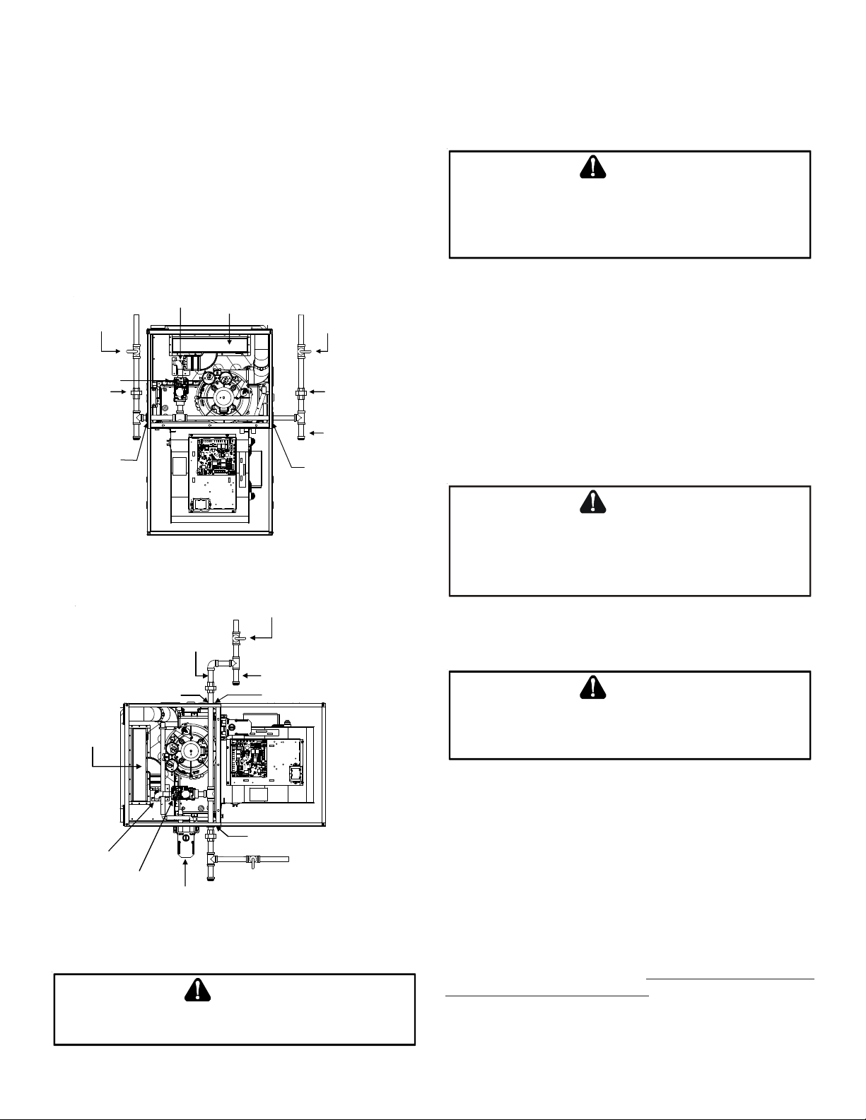
• Manual gas shut off valve
Before placing unit in operation, leak test the unit and gas connections.
A semi-rigid connector to the gas piping can be used
outside the cabinet per local codes. ½ " NPT pipe and
fittings are required. Model requires one 90 degree
elbow, one 2" nipple and additional nipple to reach
outside the cabinet.
A semi-rigid connector to the gas piping can be used outside
the cabinet per local codes. From the elbow, the length of
pipe and the fittings required will vary by the side chosen,
location of union and cabinet width. The union may be placed
inside or outside of the cabinet.
Alternate
Gas Line
Location
Gas Valve
* Ground
Joint
Pipe
Union
Plug in
Alternate
Gas Line
Hole
Manifold
Burner
Manual Shut Off Valve
(upstream from
ground joi nt
pipe unio n)
*Ground
Joint
Pipe
Union
Drip Leg
Grommet
in Standard
Gas Line
Hole
Check for leaks using an approved chloride-free soap and water
solution, an electronic combustible gas detector, or other approved testing methods.
CAUTION
TO
PREVENT PROPERTY DAMAGE OR PERSONAL INJURY DUE TO FIRE
THE FOLLOWING INSTRUCTIONS MUST BE PERFORMED REGA RDING GAS
CONNECTIONS, PRESSURE TESTING, LOCATION OF SHUTOFF VALVE AND
INSTALLATION OF GAS PIPING
.
,
NOTE: Never exceed specified pressures for testing. Higher
pressure may damage the gas valve and cause subsequent
overfiring, resulting in heat exchanger failure.
Disconnect this unit and shutoff valve from the gas supply piping
system before pressure testing the supply piping system with
pressures in excess of ½ psig (3.48 kPa).
Isolate this unit from the gas supply piping system by closing its
external manual gas shutoff valve before pressure testing supply
piping system with test pressures equal to or less than ½ psig
(3.48 kPA).
WARNING
* NOTE: Union may be inside furnace cabinet where allowed by local codes.
UPFLOW
Figure 28
Alternate
Union
Location
Grommet in
Standard Gas Line Hole
Burner
Manifold
Gas Valve
Drain Trap
Manual Shut Off Valve
(upstream from
ground joint pipe union)
Drip Leg
Plug in Alternate Gas Line Hole
Plug in Main Gas Line Hole
UPFLOW - HORIZONTAL LEFT
Figure 29
IF
THE GAS FURNACE IS INSTALLED IN A BASEMENT, AN EXCAVATED
AREA OR CONFINED SPACE, IT IS STRONGLY RECOMMENDED TO
CONTACT A CERTIFIED CONTRACTOR TO INSTALL A GAS DETECTING
WARNING DEVICE IN CASE OF A GAS LEAK
C
IRCULATING AIR
& F
ILTERS
.
DUCT WORK - AIR FLOW
WARNING
N
EVER ALLOW THE PRODUCTS OF COMBUSTION, INCLUDING CARBON
MONOXIDE, TO ENTER THE RETURN DUCT WORK OR CIRCULATION AIR
SUPPLY
.
Duct systems and register sizes must be properly designed for
the CFM and external static pressure rating of the furnace.
Ductwork should be designed in accordance with the recommended methods of “Air Conditioning Contractors of America”
Manual D.
Install the duct system in accordance with Standards of the National Board of Fire Underwriters for the Installation of Air Conditioning, Warm Air Heating and Ventilating Systems. Pamphlets
No. 90A and 90B.
GAS PIPING CHECKS
WARNING
TO
AVOID THE POSSIBILITY OF EXPLOSION OR FIRE, NEVER USE A MATCH
OR OPEN FLAME TO TEST FOR LEAKS
.
A closed return duct system must be used, with the return duct
connected to the furnace. NOTE: Ductwork must never be at-
tached to the back of the furnace. For upflow installations requiring 1800 CFM or more, use either two side returns or bottom
return or a combination of side/bottom. Flexible joints may be
used for supply and return connections to reduce noise transmis-
24
Page 25
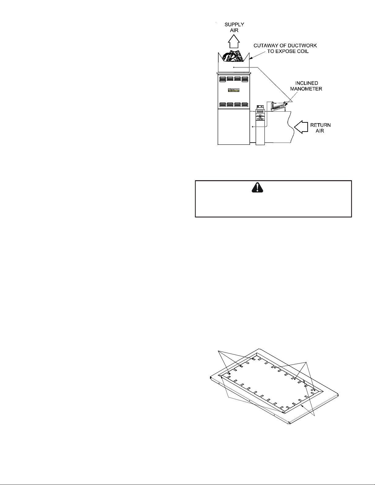
sion. T o prevent the blower from interfering with combustion air
or draft when a central return is used, a connecting duct must be
installed between the unit and the utility room wall. Never use a
room, closet, or alcove as a return air chamber .
CHECKING DUCT STATIC
Refer to your furnace rating plate for the maximum ESP (external duct static) rating.
T otal external static refers to everything external to the furnace cabinet. Cooling coils, filters, ducts, grilles, registers
must all be considered when reading your total external static
pressure. The supply duct pressure must be read between
the furnace and the cooling coil. This reading is usually taken
by removing the “A” shaped block off plate from the end on
the coil; drilling a test hole in it and reinstalling the block off
plate. Take a duct static reading at the test hole. Tape up
the test hole after your test is complete. The negative pressure must be read between the filter and the furnace blower .
Too much external static pressure will result in insufficient
air that can cause excessive temperature rise. This can cause
limit switch tripping and heat exchanger failure.
T o determine total external duct static pressure, proceed as
follows;
1. With clean filters in the furnace, use a draft gauge (inclined manometer) to measure the static pressure of the
return duct at the inlet of the furnace. (Negative Pressure)
2. Measure the static pressure of the supply duct. (Positive
Pressure)
3. The difference between the two numbers is .4” w .c.
Example:
static reading from return duct = -.1" w .c.
static reading from supply duct = .3" w .c.
total external static pressure on this system = .4" w .c.
NOTE: Both readings may be taken simultaneously and read
directly on the manometer if so desired. If an air conditioner coil or Electronic Air Cleaner is used in conjunction
with the furnace, the readings must also include theses components, as shown in the following drawing.
4. Consult proper tables for the quantity of air .
Checking Static Pressure
(80% Furnace Shown, 90% Similar)
Figure 30
WARNING
E
DGES OF SHEET METAL HOLES MAY BE SHARP
PRECAUTION WHEN REMOVING SHEET METAL FROM RETURN AIR
OPENINGS
.
. USE
GLOVES AS A
BOTTOM RETURN AIR OPENING [UPFLOW MODELS]
The bottom return air opening on upflow models utilizes a “lance
and cut” method to remove sheet metal from the duct opening
in the base pan. T o remove, simply press out the lanced sections
by hand to expose the metal strips retaining the sheet metal
over the duct opening. Using tin snips, cut the metal strips and
remove the sheet metal covering the duct opening. In the corners of the opening, cut the sheet metal along the scribe lines to
free the duct flanges. Using the scribe line along the duct flange
as a guide, unfold the duct flanges around the perimeter of the
opening using a pair of seamer pliers or seamer tongs. NOTE:
Airflow area will be reduced by approximately 18% if duct flanges
are not unfolded. This could cause performance issues and noise
issues.
CUT USING TIN SNIPS
PRESS OUT BY HAND
If the total external static pressure exceeds the maximum
listed on the furnace rating plate, check for closed dampers,
registers, undersized and/or oversized poorly laid out duct
work.
The temperature rise of the furnace must be within the temperature rise range listed on the furnace rating plate.
25
CUT FOUR CORNERS
AFTER REMOVING SHEET
METAL
Duct Flange Cut Outs
Figure 31
SCRIBE LINES OUTLINING
DUCT FLANGES
Page 26
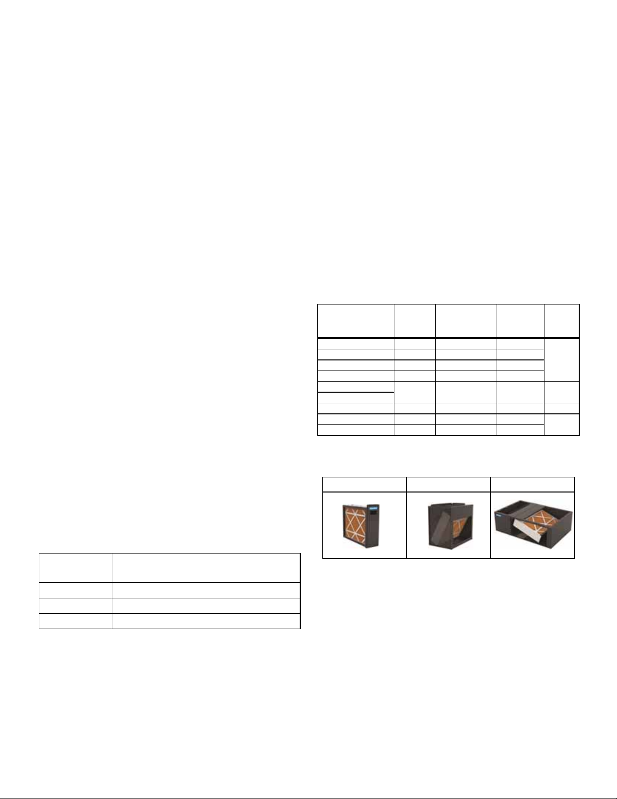
When the furnace is used in connection with a cooling unit, the
furnace should be installed in parallel with or on the upstream
side of the cooling unit to avoid condensation in the heating
element. With a parallel flow arrangement, the dampers or
other means used to control the flow of air must be adequate to
prevent chilled air from entering the furnace and, if manually
operated, must be equipped with means to prevent operation of
either unit unless the damper is in the full heat or cool position.
When the furnace is installed without a cooling coil, it is recommended that a removable access panel be provided in the outlet
air duct. This opening shall be accessible when the furnace is
installed and shall be of such a size that the heat exchanger can
be viewed for visual light inspection or such that a sampling
probe can be inserted into the airstream. The access panel
must be made to prevent air leaks when the furnace is in
operation.
cause premature heat exchanger failure. A new home may
require more frequent replacement until all construction dust
and dirt is removed. Circulating air filters are to be installed
in the return air duct external to the furnace cabinet. Consider installing an air cleaner with deep-pleated media filter
at the time of furnace installation. A deep-pleated filter with
a MERV rating of 8 (minimum) will often provide better filtration to protect equipment and the air distribution system
than a standard 1" filter and often has lower static pressure
loss than a 1" filter. Also a deep-pleated filter will typically
require less frequent replacement intervals. A void using highly
restrictive 1" filters which produce static pressure loss greater
than .25" W .C. In some installations the minimum filter size
required (consult filter sizing chart above) will not lend itself
to a filter installation on the side of the furnace. The installation of a centrally installed air cleaner cabinet or a return
duct filter installation may offer more practicality .
NOTE: In a horizontal installation the air conditioning coil
must be adequately supported by proper brackets and supports. Inadequate coil support can result in furnace cabinet
distortion and air leakage.
When the furnace is heating, the temperature of the return air
entering the furnace must be between 55°F and 100°F.
FILTERS - READ THIS SECTION BEFORE INSTALLING THE RETURN
AIR DUCT WORK
Filters must be used with this furnace. Discuss filter maintenance with the building owner. Filters do not ship with this
furnace, but must be provided, sized and installed externally by
the installer. Filters must comply with UL900 or CAN/ULCS111
standards. Damage or repairs due to the installation of the
furnace without filters is not covered under the warranty .
On upflow units, guide dimples locate the side return cutout
locations. Use a straight edge to scribe lines connecting the
dimples. Cut out the opening on these lines. NOTE: An undersized opening will cause reduced airflow .
Refer to the Filter Sizing Chart to determine filter area requirements.
Filter Sizing Chart
Clean Comfort™ brand MERV 11 air cleaners have 5¼" media
filters and are available in the following configurations shown
in Table 8. Consult your distributor for information on our
complete line of IAQ Clean Comfort™ products.
Air Cleaner
Installation L ocatio n
Si de o r bottom return 1200 CFM 16 in X 20 in x 5¼" AM11-1620-5
Si de o r bottom return 1600 CFM 16 in X 25 in x 5¼" AM11-1625-5
Si de o r bottom return 1600 CFM 20 in X 20 in x 5¼" AM11-2020-5
Si de o r bottom return 2000 CFM 20 in X 25 in x 5¼" AM11-2025-5
Sid e return
(for 2 separate returns)
Si de retu rn (Ri ght a ngl e) 2000 CFM 20 i n X 25 i n x 5¼" AM11-2025-5RA AM11-5RA
Bottom retu rn (pl atfo rm) 2000 CFM 20 i n X 25 i n x 5¼" AM11-2832-5PP
Bottom retu rn (pl atfo rm) 2000 CFM 20 i n X 25 i n x 5¼" AM11-2843-5PP
AM11-5 AM11-5RA AM11-5PP
Family Family Family
Maxim um
Heat ing
Airflow
2 X 1600 CFM 2, 16 i n X 25 i n x 5¼" AM11-3225-5 AM11-3225
Filter (Media)
Dimensions
Table 8
Part Num ber
Air
Cleaner
Family
AM11-5
AM11-5PP
Model Minimum Recommended F i lter S ize^
*MES 960403BU
*MES 960603BU
*MES960805CU
^ Larger filters may be used, filters may also be centrally located.
1 - 16 X 25 Side or Bottom
1 - 16 X 25 Side or Bottom
1 - 20 X 25 Bottom/2 - 16 X 25 Side Return
Table 7
Change filters before occupants
take ownership of a new home!
One of the most common causes of a problem in a forced air
heating system is a blocked or dirty filter. Circulating air
filters must be inspected monthly for dirt accumilation and
replaced if necessary. Failure to maintain clean filters can
Upright Installations
Depending on the installation and/or customer preference, differing filter arrangements can be applied. Filters can be installed in the central return register or a side panel external filter
rack kit (upflows). As an alternative a media air filter or electronic air cleaner can be used as the requested filter .
The following figure shows possible filter locations.
26
Page 27
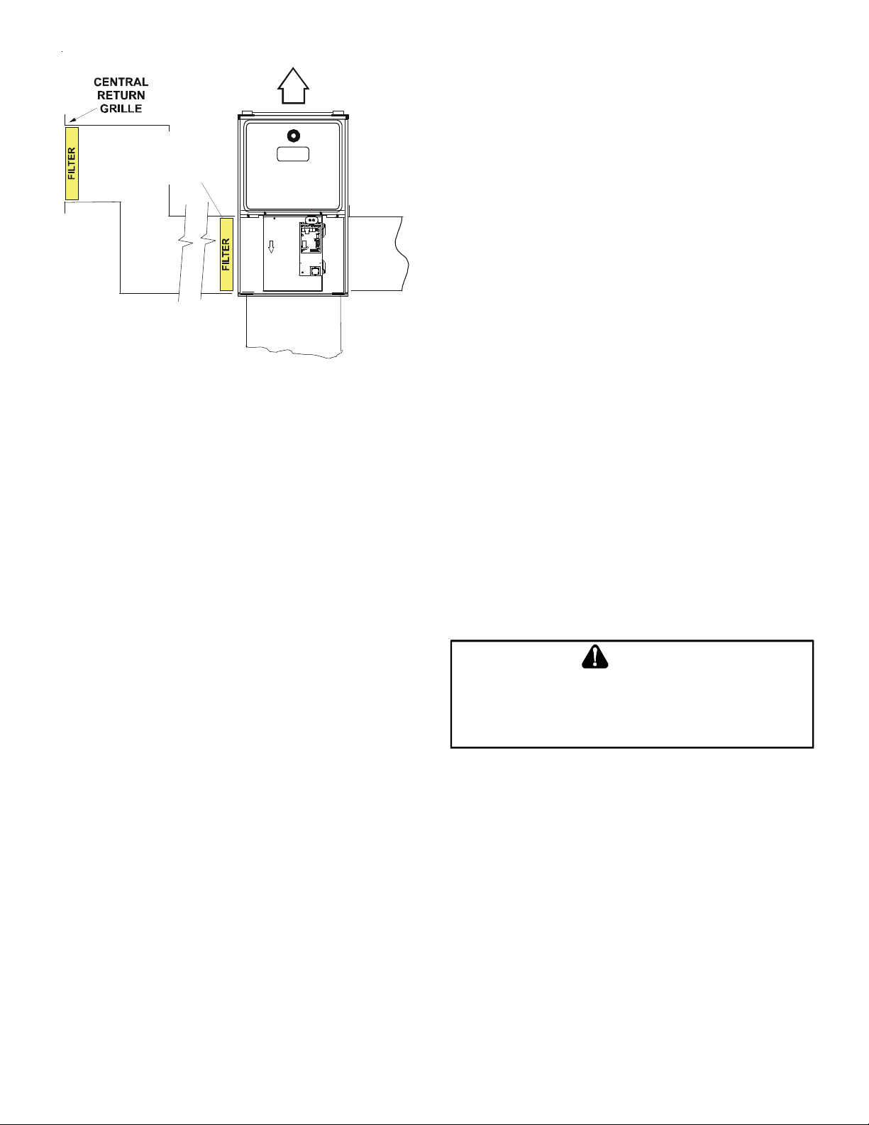
AIR FLOW
SIDE RETURN
EXTERNAL FILTER
RACK KIT
(EITHER SIDE)
Possible Upright Upflow
Figure 32
HORIZONTAL INSTALLATIONS
Filters must be installed in either the central return register or in
the return air duct work.
S
T AR TUP PROCEDURE
Furnace must have a 115 V AC power supply properly connected
and grounded. Proper polarity must be maintained for correct
operation. In addition to the following start-up and adjustment
items, refer to further information in Operational Checks section.
& A
DJUSTMENT
DRAIN TRAP PRIMING
The drain trap MUST be primed prior to furnace startup. To
prime, fill both sides of the drain trap with water . This ensures
proper furnace drainage upon startup and prohibits the possibility of flue gases escaping through the drain system.
FURNACE OPERATION
Purge gas lines of air prior to startup. Be sure not purge lines
into an enclosed burner compartment. Follow NFPA 54, National
Fuel Gas Code 8.1.
5. Move the furnace gas valve manual control to the OFF
position.
6. Wait five minutes then smell for gas. Be sure check
near the floor as some types of gas are heavier than
air.
7. If you smell gas after five minutes, immediately follow
the safety instructions in the Safety Considerations
on page 3 of this manual. If you do not smell gas
after five minutes, move the furnace gas valve
manual control to the ON position.
8. Replace the burner compartment door .
9. Open the manual gas shutoff valve external to the furnace.
10. Turn on the electrical power to the furnace.
11. Adjust the thermostat to a setting above room
temperature.
12. After the burners are lit, set the thermostat to desired
temperature.
FURNACE SHUTDOWN
1. Set the thermostat to the lowest setting.
The integrated control will close the gas valve and
extinguish flame. Following a 30 second delay , the induced
draft blower will be de-energized. The circulator blower
will shut down when the time delay expires (Time delay
is selectable on all models).
2. Remove the burner compartment door and move the
furnace gas valve manual control to the OFF position.
3. Close the manual gas shutoff valve external to the furnace.
4. Replace the burner compartment door .
GAS SUPPLY PRESSURE MEASUREMENT
GAS PRESSURE TEST
CAUTION
TO
PREVENT UNRELIABLE OPERATION OR EQUIPMENT DAMAGE, THE
INLET GAS SUPPLY PRESSURE MUST BE AS SPECIFIED ON THE UNIT
RATING PLATE WITH ALL OTHER HOUSEHOLD GAS FIRED APPLIANCES
OPERATING
.
Check for leaks using an approved chloride-free soap and water
solution, an electronic combustible gas detector, or other approved method.
FURNACE STARTUP
1. Close the manual gas shutoff valve external to the furnace.
2. T urn off the electrical power to the furnace.
3. Set the room thermostat to the lowest possible setting.
4. Remove the burner compartment door.
NOTE: This furnace is equipped with an ignition device which
automatically lights the burner . Do not try to light the burner by
hand.
The line pressure supplied to the gas valve must be within the
range specified on Table 5 on page 22. The supply pressure can
be measured at the gas valve inlet pressure tap or at a hose
fitting installed in the gas piping drip leg. The supply pressure
must be measured with the burners operating. T o measure the
gas supply pressure, use the following procedure.
1. T urn OFF gas to furnace at the manual gas shutoff valve
external to the furnace. Back inlet pressure test port
screw turn counter clockwise, not more than one turn.
2. Connect a calibrated water U tube manometer (or
appropriate gas pressure gauge) at either the gas valve
inlet pressure tap or the gas piping drip leg. See WhiteRodgers 36J22Y-204 gas valve figure below for location
of inlet pressure tap.
27
Page 28
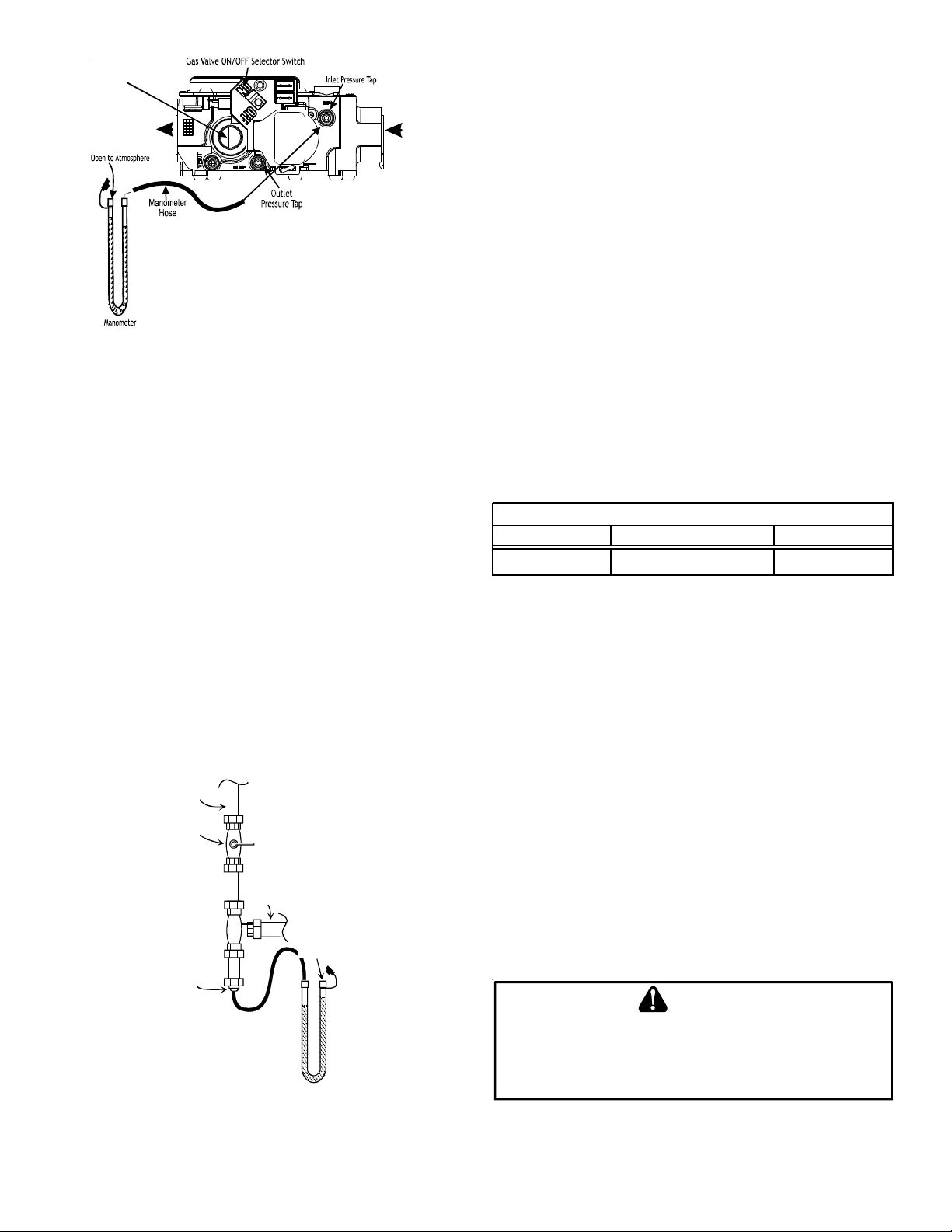
Regulator Cover
Screw
OUTLET
White-Rodgers Model 36J22Y-204
Connected to Manometer
Figure 33
INLET
NOTE: If measuring gas pressure at the drip leg, a field-supplied
hose barb fitting must be installed prior to making the hose
connection. If using the inlet pressure tap on the White-Rodgers
36J22 gas valve, then use the 36G/J Valve Pressure Check Kit,
Part No. 0151K00000S.
3. Turn ON the gas supply and operate the furnace and all
other gas consuming appliances on the same gas supply
line.
4. Measure furnace gas supply pressure with burners firing.
Supply pressure must be within the range specified in the
Inlet Gas Supply Pressure table 5, on page 22.
If supply pressure differs from table, make the necessary adjustments to pressure regulator , gas piping size, etc., and/or consult
with local gas utility .
5. Turn OFF gas to furnace at the manual shutoff valve and
disconnect manometer. Reinstall plug and tighten as
needed before turning on gas to furnace.
6. T urn OFF any unnecessary gas appliances stated in step 3.
Gas Line
Gas
Shutoff
Valve
GAS MANIFOLD PRESSURE MEASUREMENT AND ADJUSTMENT
Only small variations in gas pressure should be made by adjusting the gas valve pressure regulator. The manifold pressure
must be measured with the burners operating. T o measure and
adjust the manifold pressure, use the following procedure.
1. T urn OFF gas to furnace at the manual gas shutoff valve
external to the furnace.
2. T urn off all electrical power to the system.
3. Outlet pressure tap connections:
White-Rodgers 36J22 valve: Back outlet pressure test screw
(outlet pressure tap) out one turn (counterclockwise, not
more than one turn).
4. Connect calibrated U tube manometer (or appropriate
pressure gauge) at the gas valve outlet pressure tap.
See White-Rodgers 36J22Y-204 gas valve Figure 33 for
location of outlet pressure tap.
5. T urn ON the gas supply .
6. T urn on power and close thermostat “R” and “W” contacts
to provide a call for heat.
7. Measure the gas manifold pressure with burners firing.
Adjust manifold pressure using the Manifold Gas Pressure
table 9 shown below.
Manif old Ga s P ressure
Gas Range Nominal
Natural 2.8 - 3.2" w.c. 3.0" w.c.
Table 9
8. Remove regulator cover screw from the outlet pressure
regulator adjust tower and turn screw clockwise to increase
pressure or counterclockwise to decrease pressure. Replace
regulator cover screw .
9. T urn off all electrical power and gas supply to the system.
10.Remove the manometer hose from the hose barb fitting
or outlet pressure tap.
11.Replace outlet pressure tap: White-Rodgers 36J22 valve:
Turn outlet pressure test screw in to seal pressure port
(clockwise, 7 in-lb minimum).
12.T urn on electrical power and gas supply to the system.
13.Close thermostat contacts “R” and “W” to energize the
valve.
Gas Line
To Furnace
Open To
Atmosphere
Drip Leg Cap
With Fitting
Manometer Hose
Manometer
Measuring Inlet Gas Pressure (Alt. Method)
Figure 34
Using a leak detection solution or soap suds, check for leaks
at outlet or screw (White-Rodgers valve). Bubbles forming
indicate a leak. SHUT OFF GAS AND REPAIR ALL LEAKS IMMEDIATELY!
CAUTION
TO
PREVENT UNRELIABLE OPERATION OR EQUIPMENT DAMAGE, THE
INLET GAS SUPPLY PRESSURE MUST BE AS SPECIFIED ON THE UNIT
RATING PLATE WITH ALL OTHER HOUSEHOLD GAS FIRED APPLIANCES
OPERATING
28
.
Page 29
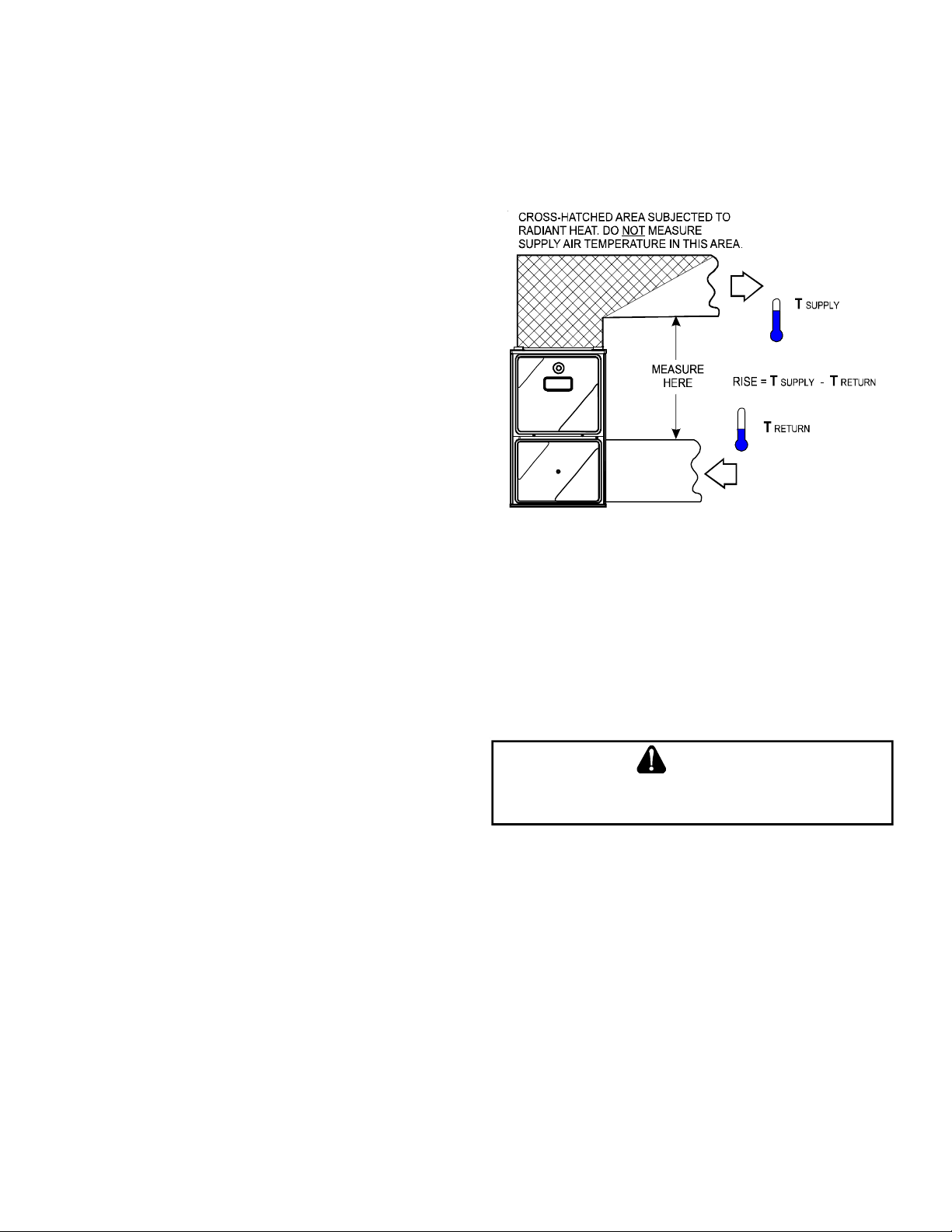
GAS INPUT RATE MEASUREMENT (NATURAL GAS ONLY)
The actual gas input rate to the furnace must never be greater
than that specified on the unit rating plate. T o measure natural
gas input using the gas meter , use the following procedure.
1. T urn OFF the gas supply to all other gas-burning appliances
except the furnace.
2. While the furnace is operating at high fire rate, time
and record one complete revolution of the gas meter dial,
measuring the smallest quantity , usually the dial that
indicates 1/2 cu. ft. per revolution. Y ou will use this
number to calculate the quantity of gas in cubic ft. if
the furnace would consume if it ran steadily for one
hour (3600 seconds).
3. If the 1/2 cu. ft. dial was used, multiply your number
x 2.
EXAMPLE: If it took 23 seconds to complete one
revolution of the 1/2 ft. dial (23 x 2 = 46).
This tells us that at this rate, it would take 46 seconds to
consume one cu. ft. of gas.
This tells us that in one hour, the furnace would consume 78
cu. ft. of gas. (3600 / 46 = 78)
3. Subtract the return air temperature from the supply air
temperature to determine the air temperature rise. Allow
adequate time for thermometer readings to stabilize.
4. Adjust temperature rise by adjusting the circulator blower
speed. Increase blower speed to reduce temperature rise.
Decrease blower speed to increase temperature rise. Refer
to Startup Procedure and Adjustment -Circulator Blower
Speeds for speed changing details.
SUPPLY
AIR
RETURN
AIR
The typical value range for 1 cu. ft. of natural gas is around
1025 BTU. Check with your gas utility, if possible. In this
example, the furnace is consuming 80,000 BTUH.
NOTE: The final manifold pressure cannot vary by
more than ± 0.2” w.c. for Natural gas f r o m t h e
specified setting. Consult your local gas supplier if
additional input rate adjustment is required.
4. Turn ON gas to and relight all other appliances turned off
in step 1. Be certain that all appliances are functioning
properly and that all pilot burners (if applicable) are
operating.
TEMPERATURE RISE
Air temperature rise is the temperature differench between
supply and return air. The proper amount of temperature
rise is usually obtained when the unit is operated at the
rated input with the “as shipped” blower speed. If the correct amount of temperature rise is not obtained, it may be
necessary to change the blower speed.
T emperature rise must be within the range specified on the unit
rating plate. An incorrect temperature rise may result in condensing in or overheating of the heat exchanger . An airflow and
temperature rise table is provided in the Specification Sheet on
page 33 applicable to your model. Determine and adjust temperature rise as follows:
1. Operate furnace with burners firing for approximately
ten minutes. Ensure all registers are open and all
duct dampers are in their final (fully or partially open)
position.
2. Place thermometers in the return and supply ducts as
close to the furnace as possible. Thermometers must
not be influenced by radiant heat by being able to
“see” the heat exchanger .
Temperature Rise Measurement
Figure 35
CIRCULATOR BLOWER SPEEDS
This furnace is equipped with a multi-speed circulator blower .
This blower provides ease in adjusting blower speeds. The
Specification Sheet applicable to your model provides an airflow table, showing the relationship between airflow (CFM)
and external static pressure (E.S.P.), for the proper selection of heating and cooling speeds.
WARNING
TO
AVOID PERSONAL INJURY OR DEATH DUE TO ELECTRICAL SHOCK
TURN
OFF
POWER TO THE FURNACE BEFORE CHANGING SPEED TAPS
1. Determine the tonnage of the cooling system installed
with the furnace. If the cooling capacity is in BTU/hr divide
it by 12,000 to convert capacity to tons.
Example: Cooling Capacity of 30,000 BTU/hr .
30,000/12,000 = 2.5 Tons
2. Determine the proper air flow for the cooling system. Most
cooling systems are designed to work with air volume
between 350 and 450 CFM per ton. Most manufacturers
recommend an air flow of about 400 CFM per ton.
Example: 2.5 tons X 400 CFM per ton = 1000 CFM
3. Select the heating speed for your model from the heating
speed chart in the Specification Sheet. The selected speed
must provide a temperature rise within the rise range
listed with the particular model.
,
.
29
Page 30

BLOWER SPEED ADJUSTMENT
T o adjust the circulator blower speed, proceed as follows:
1. T urn OFF power to the furnace.
2. Select the heating and cooling blower speeds that
match the installation requirements from the airflow
table 10 in the Specification Sheet.
3. Relocate desired motor leads to the circulator blower
heat and cool speed terminals on the integrated control
module. (T erminals are identified as HEA T and COOL).
If heating and cooling blower speeds are the same, a
jumper wire must be used between the heat and cool
terminals.
4. Connect all unused blower motor leads to the “P ARK”
terminals on the integrated control module. Any leads
not connected to the “P ARK” terminals must be taped.
5. T urn ON power to furnace.
6. Verify proper temperature rise as outlined in the
Temperature Rise section of Startup Procedure and
Adjustment.
In general lower heating speeds will: reduce electrical consumption, lower operating sound levels of the blower, and increase
the outlet air temperature delivered to the home. The speeds
available allow the blower performance to be optimized for the
particular homeowner’ s needs.
BLOWER HEAT OFF DELAY TIMINGS
NOTE: Items in this section refer to the air circulator blower
fan, NOT to the induced draft blower. The induced draft
blower timing sequence is not adjustable.
The integrated control module on all models provides a select-
able heat off delay function. The delay is factory shipped at 150
seconds but may be changed to suit the installation requirements and/or homeowner preference. Other timings available
are 90, 120 and 180 seconds. Heat cycle jumper settings on
the integrated control board are A, B, and D respectively.
N
ORMAL SEQUENCE OF OPERATION
POWER UP
The normal power up sequence is as follows:
• 115 V AC power applied to furnace.
• Integrated control module performs internal checks.
• LED will flash once at power up then remain on.
• Integrated control module monitors safety circuits
continuously.
• Furnace awaits call from thermostat.
• Igniter warm up begins after 15 second pre-purge
expires.
• Gas valve opens at the end of igniter warm up
period, delivering gas to burners and establishing
flame.
• Integrated control module monitors flame presence.
Gas valve will remain open only if flame is detected.
• Circulator blower is energized on high heat speed
following a fixed five second blower on delay.
Electronic air cleaner terminals are energized with
circulator blower .
• Furnace operates; integrated control module
monitors safety circuits continuously .
• R and W thermostat contacts open, completing the
call for heat.
• Gas valve closes, extinguishing flame.
• Induced draft blower is de-energized following a thirty
second post purge.
• HUM terminal is de-energized.
• Circulator blower continues running for the selected
heat off delay period. Factory set at 150 seconds.
If required this can be changed in the field.
• EAC terminal is de-energized
• Furnace awaits next call from thermostat.
COOLING MODE
The normal operational sequence in cooling mode is as follows:
• R,Y and G thermostat contacts close, initiating a
call for cool.
• Integrated control module performs safety circuit
checks.
• Outdoor fan and compressor are energized.
• Circulator blower is energized on the cool speed.
Following a fixed 6 second delay. Other timing
available is 45 seconds. Jumper settings on the
integrated control board is B for 45 seconds delay .
• EAC terminal is energized.
• Furnace circulator blower and outdoor cooling unit
run their appropriate speeds, integrated control
module monitors safety circuits continuously .
• R,Y and G thermostat contacts open, completing the
call for cool.
• Outdoor fan and compressor are de-energized.
• Circulator blower continues running during a cool
off delay period of 45 seconds. EAC terminals are
denergized.
• Furnace awaits next call from thermostat.
HEATING MODE
The normal operational sequence in heating mode is as follows:
• R and W thermostat contacts close, initiating a call
for heat.
• Integrated control module performs safety circuit
checks.
• Induced draft blower is energized for 30 second prepurge period causing pressure switch contacts to
close.
FAN ONLY MODE
The normal operational sequence in fan only mode is as follows:
• R and G thermostat contacts close, initiating a call
for fan.
• Integrated control module performs safety circuit
checks.
• Circulator blower is energized on heat speed.
• EAC terminal is energized.
30
Page 31
• Circulator blower runs, integrated control module
monitors safety circuits continuously .
• R and G thermostat contacts open, completing the
call for fan.
• Circulator blower is de-energized.
• EAC terminal is de-energized.
• Furnace awaits next call from thermostat.
O
PERA TIONAL CHECKS
PRESSURE SWITCHES
The pressure switches are normally-open (closed during operation) negative air pressure-activated switches. They monitor
the airflow (combustion air and flue products) through the heat
exchanger via pressure taps located on the induced draft blower
and the coil front cover. These switches guard against insufficient airflow (combustion air and flue products) through the heat
exchanger and/or blocked condensate drain conditions.
FLAME SENSOR
S
AFETY CIRCUIT DESCRIPTION
CAUTION
TO
AVOID PERSONAL INJURY OR DEATH, DO NOT REMOVE ANY
INTERNAL COMPARTMENT COVERS OR ATTEMPT ANY ADJUSTMENT
LECTRICAL COMPONE NTS ARE CONTAINED IN BOTH COMPARTM ENTS
E
C
ONTACT A QUALIFIED SERVICE AGENT AT ONCE IF AN ABNORMAL
OPERATION SHOULD DEVELOP
A number of safety circuits are employed to ensure safe and
proper furnace operation. These circuits serve to control any
potential safety hazards and serve as inputs in the monitoring
and diagnosis of abnormal function. These circuits are continuously monitored during furnace operation by the integrated control module.
.
.
.
INTEGRATED CONTROL MODULE
The integrated control module is an electronic device which, if a
potential safety concern is detected, will take the necessary precautions and provide diagnostic information through an LED.
PRIMARY LIMIT
The primary limit control is located on the partition panel and
monitors heat exchanger compartment temperatures. It is a
normally-closed (electrically), automatic reset, temperature-activated sensor . The limit guards against overheating as a result
of insufficient conditioned air passing over the heat exchanger .
AUXILIARY LIMIT
The auxiliary limit controls are located on or near the circulator
blower and monitors blower compartment temperatures. They
are a normally-closed (electrically), manual-reset sensors. These
limits guard against overheating as a result of insufficient conditioned air passing over the heat exchanger.
BURNER TEMPERATURE SWITCH
The flame sensor is a probe mounted to the burner assembly
which uses the principle of flame rectification to determine the
presence or absence of flame.
T
ROUBLESHOOTING
ELECTROSTATIC DISCHARGE (ESD) PRECAUTIONS
NOTE: Discharge body’ s static electricity before touching unit.
An electrostatic discharge can adversely affect electrical
components.
Use the following precautions during furnace installation and servicing to protect the integrated control module from damage. By
putting the furnace, the control, and the person at the same
electrostatic potential, these steps will help avoid exposing the
integrated control module to electrostatic discharge. This procedure is applicable to both installed and uninstalled (ungrounded)
furnaces.
1. Disconnect all power to the furnace. Do not touch the
integrated control module or any wire connected to the
control prior to discharging your body’s electrostatic
charge to ground.
2. Firmly touch a clean, unpainted, metal surface of the
furnace away from the control. Any tools held in a person’ s
hand during grounding will be discharged.
3. Service integrated control module or connecting wiring
following the discharge process in step 2. Use caution not
to recharge your body with static electricity; (i.e., do not
move or shuffle your feet, do not touch ungrounded
objects, etc.). If you come in contact with an ungrounded
object, repeat step 2 before touching control or wires.
4. Discharge your body to ground before removing a new
control from its container. Follow steps 1 through 3 if
installing the control on a furnace. Return any old or new
controls to their containers before touching any ungrounded
object.
The burner temperature switch is mounted on the burner
assembly to monitor the burner box temperature. It is normally closed (electrically), auto-reset sensor. This switch
guards against the burner flames not being properly drawn into
the heat exchanger .
PRESSURE SENSOR
Pressure sensor is mounted on the induced draft blower. Its
function is to regulate the induced draft blower’s speed in
order to maintain proper air-fuel ratio for clean and reliable
combustion.
TROUBLESHOOTING CHART
Refer to the Troubleshooting Codes chart for assistance in de-
termining the source of unit operational problems.
31
Page 32
FAULT CODE RETRIEVAL
The ignition control is equipped with a push button (SW1)
that can be used to display on the diagnostic LED the last
five faults detected by the control. The control must be in
Standby Mode (no thermostat inputs) to use the feature.
Depress the push button once for less than 5 seconds. Release the push button. The diagnostic LED will then display
the flash codes associated with the last five detected faults.
The order of display is the most recent fault to the least
fault. See trouble shooting guide for fault description.
• Flue pipe system: Check for blockage and/or leakage.
Check the outside termination and the connections at
and internal to the furnace.
• Heat exchanger: Check for corrosion and/or buildup
within the heat exchanger passageways.
• Burners: Check for proper ignition,and flame sense.
• Drainage system: Check for blockage and/or leakage.
Check hose connections at and internal to furnace.
• Wiring: Check electrical connections for tightness and/
or corrosion. Check wires for damage.
• Filters: Check for Blockage
CLEAR FAULT MEMORY
Replace the following “The push button (SW1) on the ignition control can be used to erase the fault code as well. The
control must be in Standby Mode (no thermostat inputs) to
use the feature. Press and hold SW1 button for more than 5
seconds, but less than 10 seconds and the control will erase
the stored fault code history. LED will display rapid green
flash to indicate the fault history has been cleared.
RESETTING FROM LOCKOUT
Furnace lockout results when a furnace is unable to achieve ignition after three attempts during a single call for heat. It is
characterized by a non-functioning furnace and a fault code
displayed. If the furnace is in “lockout”, it will (or can be) reset
in any of the following ways.
1. Automatic reset. The integrated control module will
automatically reset itself and attempt to resume normal
operations following a one hour lockout period.
2. Manual power interruption. Interrupt 115 volt power to
the furnace.
3. Manual thermostat cycle. Lower the thermostat so that
there is no longer a call for heat for 1 -20 seconds then
reset to previous setting.
NOTE: If the condition which originally caused the lockout still
exists, the control will return to lockout. Refer to the
T roubleshooting Chart for aid in determining the cause.
M
AINTENANCE
WARNING
HIGH VOLTAGE !
TO
AVOID PERSONAL INJURY OR DEATH DUE TO
ELECTRICAL SHOCK, DISCONNECT ELECTRICAL POWER
BEFORE
PERFORMING ANY SERVICE OR MAINTENANCE
.
ANNUAL INSPECTION
The furnace should be inspected by a qualified installer , or service agency at least once per year. This check should be performed at the beginning of the heating season. This will ensure
that all furnace components are in proper working order and that
the heating system functions appropriately . Pay particular attention to the following items. Repair or service as necessary.
FILTERS
FILTER MAINTENANCE
A return air filter is not supplied with this furnace; however,
there must be a means of filtering all of the return air. The
installer will supply filter(s) at the time of installation.
Improper filter maintenance is the most common cause of inadequate heating or cooling performance. Filters should be cleaned
(permanent) or replaced (disposable) every two months or as
required. When replacing a filter, it must be replaced with a
filter of the same type and size.
Become familiar with filter location and procedures for removal, cleaning and replacing them. If help is needed, contact the installer of the furnace or a qualified servicer .
FILTER REMOVAL
WARNING
HIGH VOLTAGE!
TO
PREVENT PROPERTY DAMAGE, PERSONAL INJURY OR
DEATH DUE TO ELECTRICAL SHOCK, DISCONNECT
ELECTRICAL POWER TO THE FURNACE
REMOVING THE FILTER OR PERFORMING ANY OTHER
MAINTENANCE
Depending on the installation, differing filter arrangements can
be applied. Filters can be installed in either the central return
register or a side panel external filter rack (upflow only). A media air filter or electronic air cleaner can be used as an alternate
filter. Follow the filter sizes given in the Recommended Minimum Filter size table 7 or instruction provided by the media
or electronic air cleaner manufacturer to ensure proper unit
performance.
T o remove filters from an external filter rack in an upright upflow
installation, follow the directions provided with external filter
rack kit.
.
BEFORE
HORIZONTAL UNIT FILTER REMOVAL
Filters in horizontal installations are located in the central return
register or the ductwork near the furnace.
32
Page 33
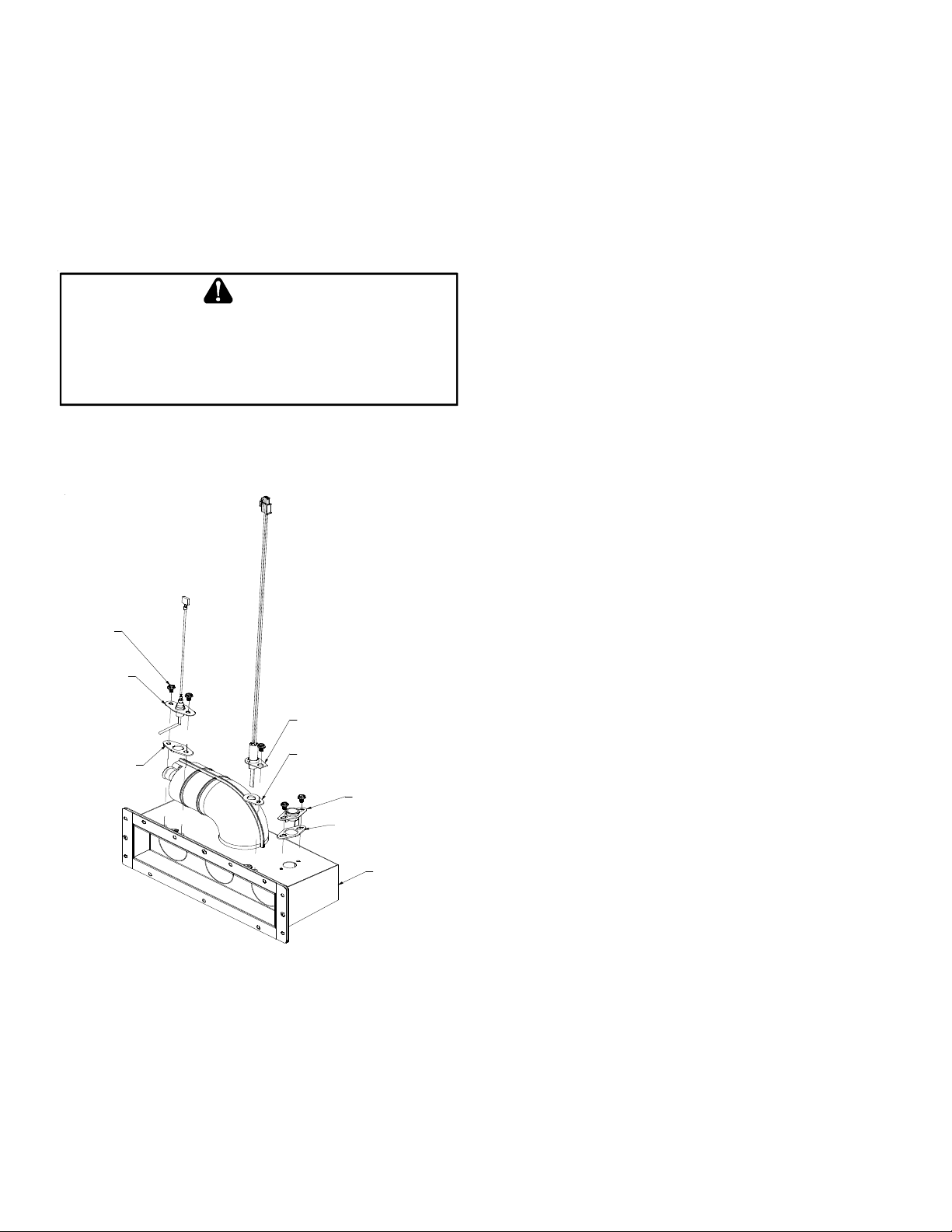
T o remove:
1. T urn OFF electrical power to furnace.
2. Remove filter(s) from the central return register or
ductwork.
3. Replace filter(s) by reversing the procedure for removal.
4. T urn ON electrical power to furnace.
INDUCED DRAFT AND CIRCULATOR BLOWERS
The bearings in the induced draft blower and circulator blower
motors are permanently lubricated by the manufacturer . No further lubrication is required. Check motor windings for accumulation of dust which may cause overheating. Clean as necessary .
MEDIA AIR FILTER OR ELECTRONIC AIR CLEANER REMOVAL
Follow the manufacturer’ s directions for service.
BURNER
WARNING
TO
PREVENT PERSONAL INJURY OR DEATH, DO NOT REMOVE ANY
INTERNAL COMPARTMENT COVERS OR ATTEMPT ANY ADJUSTMENT
E
LECTRICAL COMPONENTS ARE CONTAINED IN BOTH COMPARTMENTS
ONTACT A QUALIFIED SERVICE AGENT AT ONCE IF AN ABNORMAL
C
FLAME APPEARANCE SHOULD DEVELOP
.
The Ultra Low NOx furnace uses a premix burner . The burner
box is sealed to achieve safe and reliable operation.
SCREW
SENSOR
IGNITOR
GASKET
GASKET
LIMIT
GASKET
.
.
BURNER BOX
CONDENSATE TRAP AND D RAIN SYSTEM (QUALIFIED SERVICER
ONLY)
Annually inspect the drain tubes, drain trap, and field-supplied
drain line for proper condensate drainage. Check drain system
for hose connection tightness, blockage, and leaks. Clean or
repair as necessary .
FLAME SENSOR (QUALIFIED SERVICER ONLY)
Under some conditions, the fuel or air supply can create a nearly
invisible coating on the flame sensor. This coating acts as an
insulator causing a drop in the flame sense signal. If the flame
sense signal drops too low the furnace will not sense flame and
will lock out. The flame sensor should be carefully cleaned by a
qualified servicer using emery cloth or steel wool. Following
cleaning, the flame sense signal should be above 3 micro amps.
FLUE PASSAGES (QUALIFIED SERVICER ONLY)
The heat exchanger flue passageways should be inspected at the
beginning of each heating season.
B
EFORE LEA VING AN INST ALLATION
• Cycle the furnace with the thermostat at least three times.
V erify cooling and fan only operation.
• Review the Owner’s Manual with the homeowner and
discuss proper furnace operation and maintenance.
• Leave literature packet near furnace.
R
EP AIR AND REPLACEMENT PAR TS
• When ordering any of the listed functional parts, be sure
to provide the furnace model, manufacturing, and serial
numbers with the order .
• Although only functional parts are shown in the parts list,
all sheet metal parts, doors, etc. may be ordered by
description.
• Parts are available from your distributor .
Burner Box
Figure 36
NOTE: Location of flame sensor, igniter and burner limit
switch may vary depending on the model.
Functional P arts List-
Gas V alve Blower Motor
Gas Manifold Blower Wheel
Natural Gas Orifice Blower Mounting Bracket
Igniter Blower Cutoff
Flame Sensor Blower Housing
Burner T emperature Switch Pressure Switches
Primary Limit Switch Burner Assembly
Coil Front Cover Drain Trap
Auxiliary Limit Switch Burner Box Gasket
Transformer Integrated Control Module
Door Switch Pressure Sensor
Induced Draft Blower
Heat Exchanger with Recuperator Coil
33
Page 34
T
ROUBLESHOOTING CHAR T
Symp toms of Abn orma l
Operation
· Fur nace fails to operate. · No 1 15 volt power to
· Fur nace fails to operate. · Fur nace lockout due to a n
· Integra ted control modul e
dia gnostic LED is fla shi ng
ONE (1) fl ash.
· Furnace Fails to operate · Pressure sensor indicates
· Integra ted control modul e
dia gnostic LED is flashing
TWO (2) flas hes.
· Induced draft blower runs
continuousl y with no further
fu rna ce oper ati on .
· Integra ted control modul e
dia gnostic LED is fla shi ng
THREE (3) flashes.
Ass oci ated
LED Cod e² &
Color
· None
☼
1 Flash
LED color is
RED.
☼
2 Flashes
LED color is
RED.
☼
3 Flashes
LED color is
RED.
Fault Description(s) Possible
furnace, or no 24 volt power
to integrated control modul e.
· Integrated control module
has an internal fault.
excessive number of ignition
attempts. (3 total retries)¹
· No limits to number of
recycles.
pressure reading when it
should be zero.
5 minute lockout. Unlimited
retries. Fault is displayed
until fault condition is
corrected or CFH i s removed.
· Inducer not making
press ure s etting.
· Induced draft blower is
oper ati ng pr operl y.
5 minute lockout. Unlimited
retries. Fault is displayed
until fault condition is
corrected or CFH i s removed.
Caus es
· Manual disconnect switch OFF,
door switch open, or 24 volt wir es
improperl y connected or loos e.
· Bad integrated control module. · Check for possible shorts in
· Failure to establish flame. Cause
may be no gas to burner, bad
igniter or igniter alignment,
improper orifi ces, or
coated/oxidized or improperl y
connected or shorted flame sensor.
· Loss of flame after establishment.
Cause may be interrupted gas
suppl y, lazy burner flames
(improper gas pressure or
restriction in flue or improper
induced draft blower
performance).
· Improperly connected igniter. · Check and correct wiring.
· Bad i gniter. · Compa re igni ter res istance
· Poor unit or burner ground. · Check and correct unit
· Faulty i ntegrated control module. · Replac e bad integrated
· Faulty wiring to the pressure
sensor.
· Faulty pressure sensor. · Replace pressure sensor.
· Pressure sensor hoses blocked,
pinc hed or connected improperl y.
Bad wire connection.
· Blocked intake, blocked flue outlet
or weak induced draft bl ower.
· Ass ure 115 and 24 volt
power to furnace integrated
control module.
115 and 24 volt circuits.
Repair as necessary.
· Replace bad integra ted
control module.
· Locate and correct gas
i nterr upti on.
· Replace bad gas valve or gas
orifice size.
· Replace igniter.
· C heck fla me s ens e s i gna l.
Clean sensor if coated and/or
oxidized.
· Replace induced draft
blower pressure switch.
Inspect pressure switch
hose. Repair, if necessary.
Ins pect fl ue, bur ner o r
condensa te for blocka ge,
proper length, elbows , and
termination.
to spec. Repl ace i f necessar y.
ground wiring.
control module.
· C heck and co rr ect p res su re
sensor wiring.
· Replace induced draft
blower pressure sensor and
hoses. Repair, if necessary.
Chec k and correc t wiri ng.
· Inspect intake and flue for
blockage, proper length,
elbows, and termination.
· Replace induced draft
blower.
Corrective
Ac tio n
Cautions
& Notes
· Turn power OFF pri or
to rep ai r.
· Read precautions in
"Electr osta tic
Disc harge" s ection of
man ual .
· Turn power and ga s
OFF prior to repair.
· Igniter is fragile,
handl e with care.
· Clea n fl ame s ens or
wi th s teel wool .
· Rep la ce i gni ter with
proper repla cement
part.
· Read precautions in
“El ectr os tati c
Disc harge” section of
man ual .
· Turn power OFF prior
to rep ai r.
· Replace pressure
sensor with proper
replacement part.
· Turn power OFF pri or
to rep ai r.
· Repl ace with proper
replacement parts.
· See “Combustion and
Ventila tion Air
Requirements” and
“Ca tegor y I Ven tin g
(Vertical Venting)”
section for details.
1
2
34
Page 35
T
ROUBLESHOOTING CHART
Symp toms of Abn orma l
Operation
· Circulator blower runs
continuousl y. No furnace
operation.
· Integra ted control modul e
dia gnostic LED is fla shi ng
FOUR (4) flas hes.
· Induced draft blower and
circul ator blower runs
continuousl y. No furnace
operation.
· Integra ted control modul e
dia gnostic LED is fla shi ng
FIVE (5) flashes.
· Furnace fails to operate. · Burner temperature switch
· Integra ted control modul e
dia gnostic LED is fla shi ng SIX
(6) fl ashes.
· No furna ce opera tion . · Gas va lve c ircuit shorted. · Ba d wiri ng · Inspect and replace wiring
· Integra ted control modul e
dia gnostic LED i s fl ashi ng
SEVEN (7) fla shes.
Ass oci ated
LED Cod e² &
Color
☼
4 Flashes
LED color is
RED.
☼
5 Flashes
LED color is
RED.
☼
6 Flashes
LED color is
RED.
☼
7 Flashes
LED color is
RED.
Fault Description(s) Possible
· Primary limit circuit is
open.
· 5 minute lockout. 1 hour
lockout a fter three faul ts i n a
single CFH.
· Flame sensed with no cal l
for heat.
· 5 minute lockout. Control
continues normal operation
when fault condi tion is
corrected.
open.
· 5 minute lockout. Control
continues normal operation
when fault condi tion is
corrected.
· 5 minute lockout. · Faulty integrated control module. · Replace bad integra ted
· Insufficient conditioned air over
the hea t exc ha nger . Bl oc ked fi lter s,
restrictive ductwork, improper
circul ator blower speed, or fai led
circulator blower.
· Faulty primary limit switch. · Check primary limit. Replace
· Loose or improperly connected
wiri ng.
· Faulty i ntegrated control module.. · Replace bad integra ted
· Exces si ve fl ame. · Ch ec k an d corr ect ga s
· Blocked flue, air inl et pipe, and/or
burner intake and mesh, or fail ed
induced draft blower.
· Loose or improperly connected
wiri ng.
· Faulty burner temperature switch. · Check induced draft blower
Caus es
· Chec k circ ula tor bl ower
speed and performance.
Co rre ct s peed or rep la ce
blower if necessary. · Check
fil ters a nd ductwork for
blockage. Clean fil ters or
remove obstruction.
if necess ary.
· Chec k position of h eat
exchanger shield.
· Tighten or correct wiring
connection.
control module.
supply pressure.
· Replace bad gas valve or gas
orifice size.
· Check flue, ai r inl et pipi ng,
and burner intake and mesh
for blocka ge, proper length,
elbows, and termination.
Co rre ct a s nec ess ar y.
· Check induced dra ft blower
fo r p rop er p erfo rma nc e.
Replace, if necessary.
· C heck bur ner temper atu re
swi tch. Repl ac e i f nec ess ary.
fo r p rop er p erfo rma nc e.
Replace, if necessary.
· Tighten or correct wiring
connection.
as needed.
control module.
Corrective
Ac tio n
Cautions
& Notes
· Turn power OFF pri or
to rep ai r.
· Repl ac e blower with
co rr ect r epl ac ement
part.
· Replace pri mary
switch with proper
replacement part.
· Turn power OFF pri or
to rep ai r.
· See “Vent/Fl ue Pi pe”
section for piping
detail s.
· Repl ace induced draft
blower with proper
replacement part.
· Replace burner
tempera ture swi tch
with c orrect
replacement part.
· Turn power OFF pri or
to rep ai r.
· Read precautions in
“El ectr os tati c
Disc harge” section of
man ual .
2
35
Page 36
T
ROUBLESHOOTING CHAR T
Symp toms of Abn orma l
Operation
· LED is s teady on Steady
· Integra ted control modul e
dia gnostic LED is fla shi ng
ONE (1) fl ash.
· Integra ted control modul e
dia gnostic LED is fla shi ng
TWO (2) flas h.
· Integra ted control modul e
dia gnostic LED is fla shi ng
THREE (3) flash.
· LED is s teady on Steady
· Integra ted control modul e
dia gnostic LED is fla shi ng
rapi dly.
· Integra ted control modul e
dia gnostic LED is fla shi ng
ONE (1) fl ash.
Ass oci ated
LED Cod e² &
Color
LED color
AMBER.
☼
1 Flash
LED color is
AMBER.
☼
2 Flash
LED color is
AMBER.
☼
3 Flash
LED color is
AMBER.
LED color
GREEN.
Rapid flash
LED color is
GREEN.
☼
1 Flash
LED color is
GREEN.
Fault Description(s) Possible
· OEM test mode · N/A
· Low fl ame sens e · F la me s ens or in co rrec tl y
posi tioned in burner flame.
· Flame sensor is coated/oxidized. · Clean flame rod. · Clean flame s ens or
· Lazy burner flame due to improper
gas pressure or combustion air.
· ID plug failure (Applies only
to certa in model s with ID
plug).
· Integrated control module
fuse is blown.
· Normal opera ti on. · N/A
· Clear error history. · N/A · Press and hold the SW1
· Call for heating. · N/A
· Improper ID plug. · Replace ID pl ug. · Turn power OFF pri or
· Blown fuse. · Replace integrated control
Caus es
· I ns pec t fo r p rop er s ens or
alignment.
· Co mpar e cur rent ga s
press ure to rating pla te info.
Adj ust as needed.
modul e fuse (3A).
button for more than 5 secs
results in the display of this
mode. Releas i ng the Button
during this indicati on wil l
ca use the Err or Hi stor y to be
cleared.
Corrective
Ac tio n
Cautions
& Notes
· Turn power OFF pri or
to rep ai r.
wi th s teel wool .
· See r ati ng p la te for
proper gas press ure.
to rep ai r.
· Turn power OFF pri or
to rep ai r.
· The button must be
releas ed within 5
seconds after
the LED begi ns this
flash sequence.
· Integra ted control modul e
dia gnostic LED is fla shi ng
TWO (2) flas h.
· Integra ted control modul e
dia gnostic LED is fla shi ng
THREE (3) flash.
· Integra ted control modul e
dia gnostic LED has THREE (3)
rapid fla sh's.
· Abnormal hi gh pitch noise
during burner operation.
☼
2 Flash
LED color is
GREEN.
3 Flash
LED color is
GREEN.
3 Rapi d
Flas h's
LED color is
GREEN.
· None · Abnormal combustion
· Call for cool ing. · N/A
☼
· Continuous fan opera tion. · N/A
☼
· ID plug installed (Applies
only to certain models with
ID plug).
noise.
· N/A · For control with unit-
· Insuffi cient combustion a ir or
high i nput.
· Blocked flue and/or air inlet pipe,
or faulty induced draft blower or
pr ess ur e s ens or.
spec ifi c p rogr ammi ng
imbedded in the CPU, this
indicates at power-up that an
valid ID plug is installed.
· C heck and co rr ect g as
supply and manifold
press ures. See Table 5 and
Table 9 for additional
information.
· Replace bad gas valve or gas
orifice size.
· Check flue and ai r inlet
piping for blockage, proper
length, elbows, and
termination. Correct as
necessary.
· Check induced dra ft blower
and pressure sensor for
proper perfor manc e.
Replace, if necessary.
· The control will use
the alternate
parameters.
· Turn power and ga s
OFF prior to repair.
· See “Vent/Fl ue Pi pe”
section for piping
detail s.
· Repl ace induced draft
blower or pressure
sensor with proper
replacement part.
2
36
Page 37
A
IRFLOW
*MES96***
*MES96 0403BU
*MES96 0603BU
*MES96 0805CU
0.1 0.2 0.3 0. 4 0. 5
EXTERN AL STA TIC PR ESSURE (i nche s wate r colu mn)
Wire Color Function Tons AC CFM Rise CFM Rise CFM Rise CFM Rise CFM Rise CFM CFM CFM
Red Hig h-Coo l 3 1350 NA 1310 N A 1273 NA 1234 NA 1198 N A 1156 1117 1078
Bl ue Me d Hi - H eat 2.5 1247 29 12 12 30 1167 31 1129 32 1087 33 1043 997 95 2
Brow n Med Low 2 1151 31 1107 32 1067 35 1021 35 977 36 928 880 835
Bl ack Low 1.5 922 39 870 41 819 43 763 NA 704 N A 643 592 539
Ora nge Fa n On ly 1 779 N A 661 N A 588 N A 516 N A 4 55 NA 394 352 N /A
Red Hig h-Coo l 3 1364 NA 1332 N A 1285 NA 1246 NA 1206 N A 1170 1127 1083
Bl ue Me d Hi - H eat 2.5 1259 42 12 14 44 1175 45 1135 47 1091 49 1053 1008 957
Brow n Med Low 2 1165 46 1121 48 1073 50 1033 52 984 54 929 876 832
Bl ack Lo w 1.5 936 57 884 60 829 N A 770 N A 706 N A 645 593 539
Ora nge Fan onl y 1 815 NA 665 NA 596 N A 517 NA 451 NA 396 3 45 N a
Red Hig h-Coo l 5 2298 NA 2260 N A 2222 NA 2182 NA 2149 N A 2114 2087 2022
Blu e Med Hi - Heat 4 1701 42 1641 43 1600 45 1548 46 1502 47 1454 1411 1366
Brow n Med Low 3.5 1575 45 1528 47 1478 48 1426 50 1373 52 1323 1272 1220
Bl ack Low 2.5 1302 55 1220 60 1187 N A 1126 NA 1063 N A 1004 936 871
Oran ge F an onl y 1.5 1056 NA 981 N A 915 N A 842 NA 764 NA 683 604 540
0.6 0.7 0. 8
AIRFLOW AND TEMPERATURE RISE SPECIFICATION SHEET FOR *MES96*** MODELS
Table 10
1. CFM in chart is without filter(s). Filters do not ship with this furnace, but must be provided by the installer. If the furnace requires two return
filters, this chart assumes both filters are installed.
2. For most jobs, about 400 CFM per ton when cooling is desirable.
3. INSTALLATION and/or BLOWER SPEED CAN BE ADJUSTED TO OBTAIN TEMPERATURE RISE WITHIN THE RANGE SPECIFIED ON THE RATING PLATE.
4. The chart is for information only. For satisfactory operation, external static pressure must not exceed value shown on rating plate. The shaded
area indicates ranges in excess of maximum external static pressure allowed when heating. The data for 0.6" w.c. to 0.8" w.c. is shown for
air conditioning purposes only.
5. At higher altitudes, a properly derated unit will have approximately the same temperature rise at a particular CFM, while the ESP at that CFM
will be lower.
37
Page 38
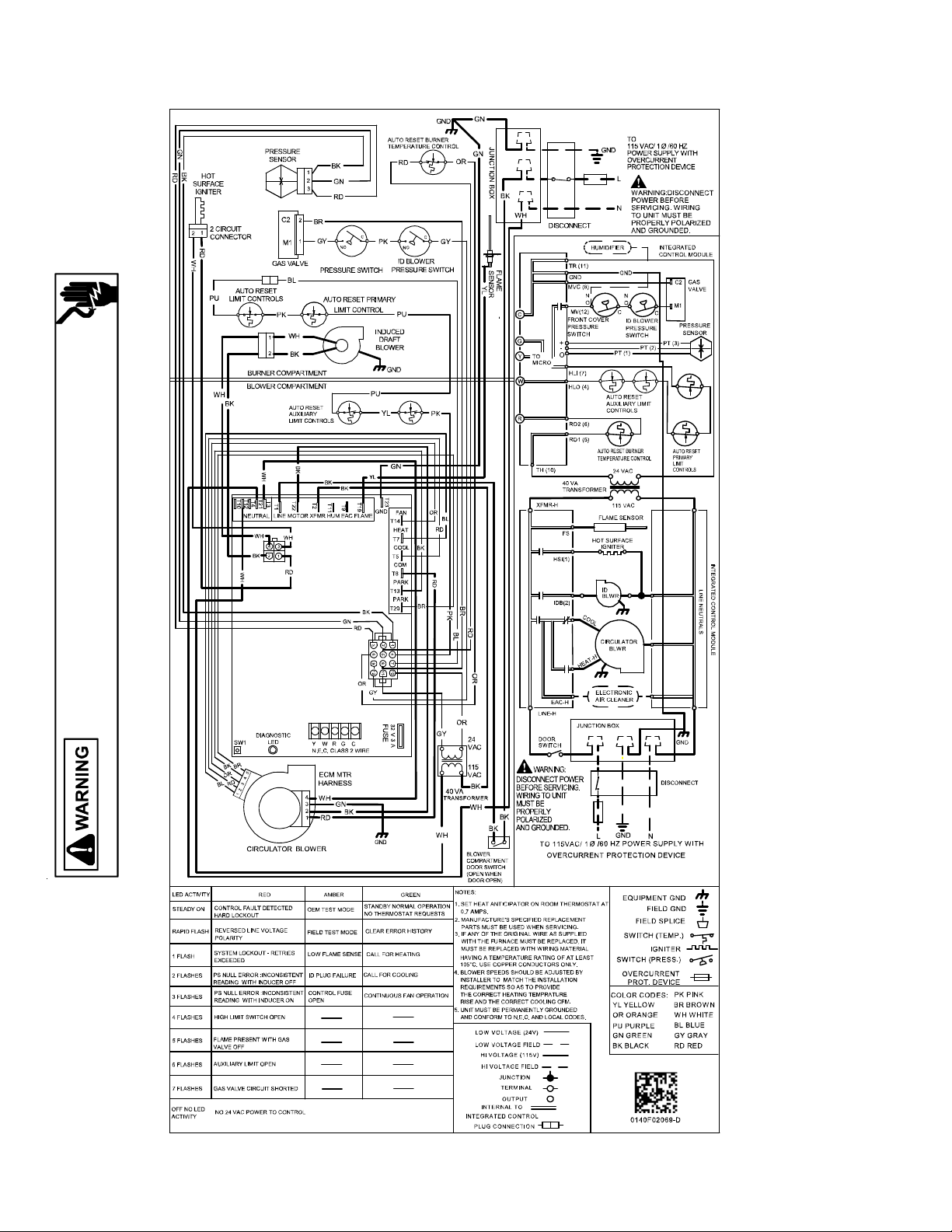
W
IRING
D
IAGRAM
*MES96***
HIGH VOLTAGE!
Disconnect ALL power before servicing or installing this unit. Multiple
power sources may be present. Failure to do so may cause property
damage, personal injury or death.
Wiring is subject to change. Always refer to the wiring diagram on the unit for the most up-to-date wiring.
38
Page 39

Page Left Intentionally Blank
39
Page 40
CUSTOMER FEEDBACK
We are very interested in all product comments.
Please fill out the feedback on one of the following links:
Goodman® Brand Products:
(http://www.goodmanmfg.com/about/contact-us).
Amana® Brand Products: (http://www.amana-hac.com/about-us/contact-us).
You can also scan the QR code on the right for the product brand
GOODMAN® BRAND
you purchased to be directed to the feedback page.
PRODUCT REGISTRATION
Thank you for your recent purchase. Though not required to get the protection of
the standard waranty, registering your product is a relatively short process, and
entitles you to additional warranty protection, except that failure by California and Quebec
residents to register their product does not diminsh their warranty rights.
GOODMAN® BRAND
For Product Registration please register by following this link:
Goodman® Brand Products: (https://www.goodmanmfg.com/product-registration).
Amana® Brand Products: (http://www.amana-hac.com/product-registration).
You can aslo dcan the QR code on the right to be directed to the Product Registration Page.
AMANA® BRAND
AMANA® BRAND
5151 San Felipe Suite 500
Houston, TX 77056
www.goodmanmfg.com • www.amana-hac.com
© 2014-2019 Goodman Manufacturing Company, L.P.
is a registered trademark of Maytag Corporation or its related companies and is used under license. All rights reserved.
40
 Loading...