How it Works
Log In / Sign Up
Buy Points
How it Works
FAQ
Contact Us
Questions and Suggestions
Users
Goodman
Loading...
G
GKS90905DXAB
GKS90905DXAC
GKS91155DX
3
GKS91155DXAA
GKS91155DXAB
GKS91155DXAC
GKS91155DXAD
GM9C80
4
GM9C80,GC9C80
GM9C96
5
GM9S80
6
GM9S80,GC9S80
GM9S92
2
GM9S96
4
GM9S96,GC9S96
GME8
4
GME80603BNB
GME80603B Series
2
GME80703BXC
GME80703BXCA
GME80703BXCB
GME80704BXAA
GME80704BXAB
GME80704BXAC
GME80805C Series
2
GME80805D Series
GME80905CXAA
GME80905CXAB
GME80905CXAC
GME80905CXC
GME80905CXCA
GME80905CXCB
GME81005C Series
2
GME81155CXAA
GME81155CXAB
GME81155CXAC
GME81155CXC
GME81155CXCA
GME81155CXCB
GME95
4
GME950403BXAA
GME950603BXAA
GME950805CXAA
GME951005DXAA
GMEC80
4
GMEC80,GCEC80
3
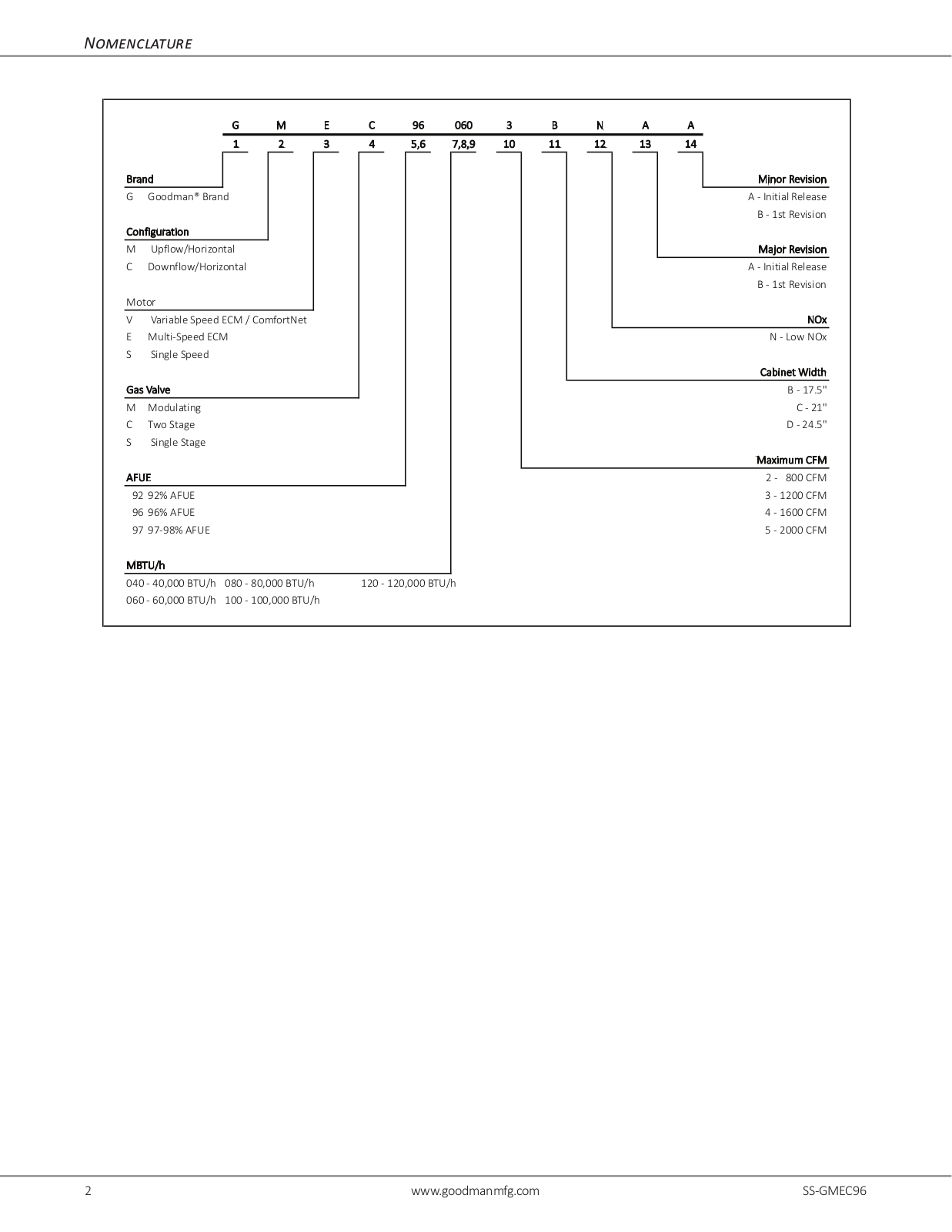
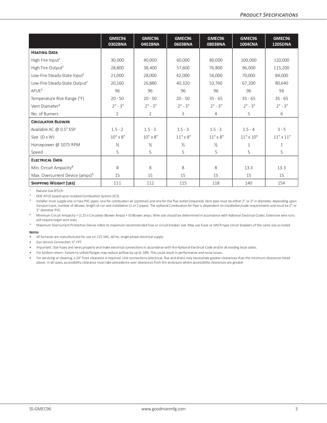
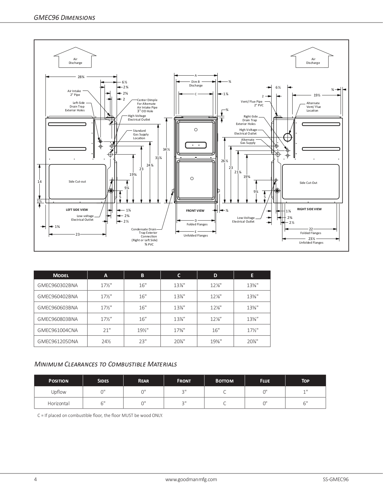
GMEC96
10
GMEC960302BN
GMEC960302BNA
GMEC960402BN
GMEC960603BN
GMEC960803BN
GMEC961004CN
GMEC961205DN
GMEC96,GCEC96
GMES92
3
GMES96
4
GMES96,GCES96
GME series
GMH8
5
GMH80403ABB
GMH80453ANCA
GMH80453ANCB
GMH80453AXCA
GMH80453AXCB
GMH80603ABB
GMH80604BBB
GMH80703AN
GMH80703ANCA
GMH80703ANCB
GMH80703AXCA
GMH80703AXCB
GMH80704BN
GMH80704BNCA
GMH80704BNCB
GMH80704BXCA
GMH80704BXCB
GMH80803BBB
GMH80804BBB
GMH80805CBB
GMH80903BN
GMH80903BNCA
GMH80903BNCB
GMH80904BN
GMH80904BNCA
GMH80904BNCB
GMH80904BXCA
GMH80904BXCB
GMH80905CN
GMH80905CNCA
GMH80905CNCB
GMH80905CXCA
GMH80905CXCB
GMH81005CBB
GMH81155CN
GMH81155CNCA
GMH81155CNCB
GMH81155CXCA
GMH8 Series
GMH series
Loading...
Loading...
Nothing found
GMEC960302BNA
User Manual
12 pgs
618.26 Kb
0
Table of contents
Loading...
Goodman GMEC960302BNA User Manual
...
Goodman User Manual
Download
Specifications and Main Features
Frequently Asked Questions
User Manual
Download
Page 1
Page 2
Page 3
Page 4
Page 5
Page 6
Page 7
Page 8
Page 9
Page 10
Page 11
Page 12
Loading...
+
hidden pages
Unhide
You need points to download manuals.
1 point = 1 manual.
You can buy points or you can get point for every manual you upload.
Buy points
Upload your manuals
 Loading...