

Page 1
GAS-FIRED WARM AIR FURNACE
USER’S INFORMATION MANUAL
WARNING
IF
THEINFORMATIONINTHESEINSTRUCTIONSISNOTFOLLOWED
EXACTLY,AFIREOREXPLOSIONMAYRESULTCAUSINGPROPERTY
,
DAMAGE
PERSONALINJURYORLOSSOFLIFE
DO
NOTSTOREORUSEGASO LINEOROTHERFLAMMABLEVAPORSAND
LIQUIDSINTHEVICINITYOFTHISORANYOTHERAPPLIANCE
.
WHATTODOIFYOUSMELLGAS:
DO
NOTTRYTOLIGHTANYAPPLIANCE
•
D
ONOTTOUCHANYELECTRICALSWITCH;DONOTUSEANYPHONE
•
INYOURBUILDING
I
MMEDIATELYCALLYOURGASSUPPLIERFROMANEIGHBOR’S
•
PHONE
.F
I
FYOUCANNOTREACHYOURGASSUPPLIER,CALLTHEFIRE
•
DEPARTMENT
I
NSTALLATIONANDSERVICEMUSTBEPERFORMEDBYAQUALIFIED
INSTALLER,SERVICEAGENCYORTHEGASSUPPLIER
.
OLLOWTHEGASSUPPLIER’SINSTRUCTIONS
.
.
.
Installer - Affix this manual, Installation Guide, and Warranty adjacent to the appliance.
.
.
Owner - Read and keep all product literature in a safe place for future reference.
WARNING
S
HOULDOVERHEATINGOCCURORTHEGASSUPPLYFAILTOSHUTOFF
TURNOFFTHEMANUALGASSHUTOFFVALVEEXTERNALTOTHE
FURNACEBEFORETURNINGOFFTHEELECTRICALSUPPLY
P
RODUCTCONTAINSFIBERGLASSWOOL
INTHISPRODUCTDURINGINSTALLATION,MAINTENANCEORREPAIR
WILLEXPOSEYOUTOFIBERGLASSWOOL
LUNGCANCE R
ALIFORNIATOCAUSECANCE R
C
FURTHERINFORMATION,CONSULTMATERIALSAFETYDATASHEETS
AVAILABLEFROMTHEADDRESSSHOWNBELOW
.
.(F
IBERGLASSWOOLISKNOWNTOTHESTATEOF
RECOGNIZE THIS SYMBOL AS A SAFETY PRECAUTION.
,
TO
DEATHDUETOELECTRICALSHOCK,THEFURNACEMUSTBELOCATEDTO
PROTECTTHEELECTRICALCOMPONENTSFROMWATER
WARNING
.D
ISTURBINGTHEINSULATION
.B
REATHINGTHISMAYCAUSE
.)TO
REDUCEEXPOSUREORFOR
WARNING
PREVENTPOSSIBLEPROPERTYDAMAGE,PERSONALINJURYOR
.
.
Part No. HI-115C
Printed in USA
Due to policy of continual product
improvement, the right is reserved
to change specifications and design
without notice.
©
2004-2006, 2010, 2012 Goodman Company, L.P.
Effective: 02/12
Page 2

Contents
IMPORTANT NOTE TO THE OWNER REGARDING PRODUCT WARRANTY ............................................................. 3
NIT LOCATION .............................................................................................................. 3
U
NIT INSTALLATION ........................................................................................................... 4
U
Air Requirements ...........................................................................................................................4
Combustion Air..............................................................................................................................4
Indoor Humidity ............................................................................................................................5
Propane (LP) Gas Installations Only ....................................................................................................5
Thermostat Functions .....................................................................................................................5
Furnace Operation .........................................................................................................................6
FURNACE START-UP .......................................................................................................... 6
URNACE SHUT DOWN ........................................................................................................ 6
F
OCKOUT RESET .............................................................................................................. 6
L
Routine Maintenance ......................................................................................................................7
ANNUAL INSPECTION .......................................................................................................... 7
OTORS ..................................................................................................................... 7
M
ILTERS ...................................................................................................................... 7
F
Troubleshooting / Before You Request a Service Call...............................................................................8
Safety Labels ................................................................................................................................9
2
Page 3
Dear Homeowner, please recognize the following safety information. This information will alert you to the potential
for personal injury.
WARNING - Indicate hazards or unsafe practices which
COULD result in severe personal injury or death.
WARNING
T
HISPRODUCTCONTAINSORPRODUCESACHEMICALORCHEMICALS
WHICHMAYCAUSESERIOUSILLNESSORDEATHANDWHICHARE
KNOWNTOTHESTATEOFCALIFORNIATOCAUSECANCER,BIRTH
DEFECTSOROTHERREPRODUCTIVEHARM
.
To register your Amana® brand unit, go to
www.amanahac.com and click “Warranty R egistration” . Complete the
registration as prompted.
Product limited warranty certificates for models currently
in production can be viewed at
www.goodmanmfg.com or
www.amana-hac.com. If your model is not currently in
production or does not appear on the website, please contact your installing contractor or contact customer service
(877-254-4729) to obtain a copy of your warranty certificate.
Before using this manual, check the serial plate for
proper model identification.
WARNING
TO
AVOIDPOSSIBLEEQUIPMENTDAMAGE,PERSONALINJURY,FIREOR
DEATH,THEFOLLOWINGINSTRUCTIONSMUSTBEOBSERVEDREGARDING
UNITLOCATION,AIRREQUIREMENTSANDOPERATINGPROCEDURES
.
WARNING
H
EATINGUNITSHOULDNOTBEUTILIZEDWITHOUTREASONABLE
ROUTINE,INSPECTION,MAINTENANCEANDSUPERVISION
BUILDINGINWHICHANYSUCHDEVICEISLOCATEDWILLBEVACANT
CARESHOULDBETAKENTHATSUCHDEVICEISROUTINELYINSPECTED
MAINTAINEDANDMONITORED.INTHEEVENTTHATTHEBUILDING
MAYBEEXPOSEDTOFREEZINGTEMPERATURESANDWILLBEVACANT
ALLWATER‐BEARINGPIPESSHOULDBEDRAINED,THEBUILDINGSHOULD
BEPROPERLYWINTERIZED,ANDTHEWATERSOURCECLOSED.INTHE
EVENTTHATTHEBUILDINGMAYBEEXPOSEDTOFREEZING
TEMPERATURESANDWILLBEVACANT,ANYHYDRONICCOILUNITS
SHOULDBEDRAINEDASWELLAND,INSUCHCASE,ALTERNATIVEHEAT
SOURCESSHOULDBEUTILIZED
.
.IF
THE
,
,
,
,
IMPORTANT NOTE TO THE OWNER REGARDING PRODUCT
WARRANTY
Your warranty certificate is supplied as a separate document with the unit installed by your contractor. Read the
limited warranty certificate carefully to determine what is
and is not covered and keep the warranty certificate in a
safe place. If you are unable to locate the warranty certificate please contact your installing contractor or contact
customer service (877-254-4729) to obtain a copy.
IMPORTANT: To receive the Lifetime Heat Exchanger Limited Warranty (good for as long as you own your home) and
the 10-year Parts Limited W arranty , online registration must
be completed within 60 days of installation. Online registration is not required in California or Quebec. Complete
warranty details available from your local dealer or, for
Goodman® brand products, visit www.goodmanmfg.com,
and for Amana® brand products, visit www.amana-hac.com.
To register your Goodman® brand unit, go to
www.goodmanmfg.com and click “Warranty Registration”.
Complete the registration as prompted.
The installation and servicing of this equipment must be
performed by qualified, experienced technicians only.
UNIT LOCATION
1. The furnace area and the vicinity of any other gas appli-
ances must be kept clear and free of combustible materials, gasoline, and other flammable vapors and liquids.
Also, do not store or use flammable items such as paint,
varnish, or lacquer in the area.
2. Do not store or use chlorine or fluorine products
(bleaches, cements, strippers, aerosols) near the unit.
They can corrode the heat exchanger.
3. Do not use the furnace closet as storage for brooms,
mops, brushes and oily rags or cloths. The area must be
kept clear, clean and free of lint. Furnace must be kept
free and clear of exposed or loose insulation materials
in the area of installation. Examine the furnace area
when the furnace or additional insulation is added since
some insulation materials may be combustible.
4. Make sure the furnace is always connected to an ap-
proved vent, in good condition, to carry combustion products outdoors.
5. Familiarize yourself with the controls that shut off the
gas and electrical power to the furnace. If the furnace
is to be shut down at the end of the heating season,
turn off both the gas and electrical power. For safety,
always turn the gas and electrical power off before performing service or maintenance on the furnace.
6. Establish a regular maintenance schedule to insure effi-
cient and safe operation of the furnace. The furnace
should be checked at the beginning of each heating and
cooling season by a qualified service technician.
WARNING
TO
AVOIDPERSONALINJURYORFIRE,MINIMUMCLEARANCESTO
COMBUSTIBLESURFACESMUSTBEFOLLOWED
.
7. Make certain the required clearances for the furnace
are always maintained. These clearances are listed on
the furnace clearance label. If any question develops,
contact the installer of the furnace or another qualified
servicer.
3
Page 4
UNIT INSTALLATION
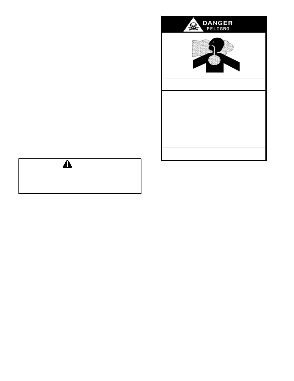
CARBON MONOXIDE POISONING HAZARD
Examine the furnace installation to determine the following:
1. All flue product carrying passages external to the furnace (i.e. chimney, vent connector) are clear and free
of obstructions.
2. The vent connector is in place, slopes upward and is
physically sound without holes or excessive corrosion.
3. The return air duct connection is physically sound, sealed
to the furnace casing, and terminates outside the space
containing the furnace.
4. The physical support of the furnace is sound without
sagging, cracks, or gaps around the base so as to provide a seal between the support and the base.
5. There are no obvious signs of deterioration of the furnace.
6. Check for proper burner flame performance. Flame
should extend directly outward from burners without
curling, floating, or lifting off.
AIR R
TO
SUFFICIENTFRESHAIRFORPROPERCOMBUSTIONANDVENTILATIONOF
FLUEGASESMUSTBESUPPLIED
SUPPLIEDINTOTHEFURNACEAREA
Improved construction and additional insulation in homes
have reduced the heat loss and made these homes much
tighter around doors and windows so that air infiltration is
minimal. This creates a problem to supply ventilation and/
or combustion air for gas fired or other fuel burning appliances. Any use of appliances that pull air out of the house
(clothes dryers, exhaust fans, fireplaces, water heaters,
non-direct vent furnaces, etc.) could reduce combustion
air to the furnace.
If fuel-burning appliances are starved for air, the flue gases
produced may not vent outdoors properly. These flue gases
may include carbon monoxide.
EQUIREMENTS
WARNING
AVOIDPROPERTYDAMAGE,PERSONALINJURYORDEATH
.M
OSTHOMESREQUIREOUTSIDEAIRBE
.
,
Special Warning for Installation of Furnaces or Air Hand ling Units in
Enclosed Areas such as Garages, Utility Rooms or Parking Areas
Carbon monoxide producing devices (such as an automobile, space
heater, gas water heater, etc.) should not be operated in enclosed areas
such as unventilated garages, utility rooms or parking areas because of
the danger of carbon monoxide (CO) poisoning r esulting from the exhaust
emissions. If a furnace or air handler is ins talled in an enclosed area such
as a garage, utility room or parking area and a carbon monoxide producing
device is oper ated therein, there must be adequate, direct outside
ventilation.
This ventilation is necessary to avoid the danger of CO poisoning which
can occur if a carbon monoxide producing device continues to o perate in
the enclose d area. Carbon monoxide emiss ions can be (re)ci rculated
throughout t he structure if the furnace or air handler is operating in any
mode.
CO can cause serious illness including permanent brain damage or death.
B10259-216
Carbon monoxide or “CO” is a colorless and odorless gas
produced when fuel is not burned completely or when the
flame does not receive sufficient oxygen.
Be aware of these air starvation signals which indicate
conditions that my result in carbon monoxide or that
carbon monoxide may be present:
1. Headaches, Nausea, Dizziness, Flu-like symptoms.
2. Excessive humidity, heavily frosted windows or a moist
“clammy” feeling in the home.
3. Smoke from a fireplace will not draw up the chimney.
4. Flue gases that will not draw up the appliance vent pipe.
C
OMBUSTION
A
IR
The air for combustion and ventilation can also (where local codes permit) be obtained from the surrounding unconfined space or louvered closet door. Observe the following
precautions concerning air availability:
• When a furnace is installed in a closet and the closet
door is louvered, DO NOT OBSTRUCT LOUVERS. Louvers must be open and clear to provide combustion air
to the furnace.
• When a furnace is installed in a confined space within
a home and the air for combustion and ventilation enters the space through ducts from the outside, be sure
to routinely check the entering and outlet, grilled openings to verify that they are always clear and clean.
• Do not partition off a small area around the furnace
utilizing a non-louvered door. This could obstruct the
combustion air from reaching the furnace.
4
Page 5
I
NDOOR
H
UMIDITY
Relative humidity is the amount of water vapor in the air
relative to the amount the air can hold at the same temperature. The colder the air; the less moisture it can hold.
As air is warmed, its ability to hold moisture is increased.
Relative humidity is important to your health and home as
proper humidification helps reduce respiratory difficulties
and helps improve the indoor air quality.
A good relative humidity is one just high enough to barely
start condensation along the lower edges or lower corners
of the windows. More than that can be damaging.
Frequent fogging or excessive condensation on inside windows indicates the indoor humidity level is too high for
outdoor weather conditions. Damage to the building may
result if the condition persists. Condensation on inside of
storm windows indicates a poor seal inside windows. Adding weather-stripping to tighten inside windows usually corrects this problem.
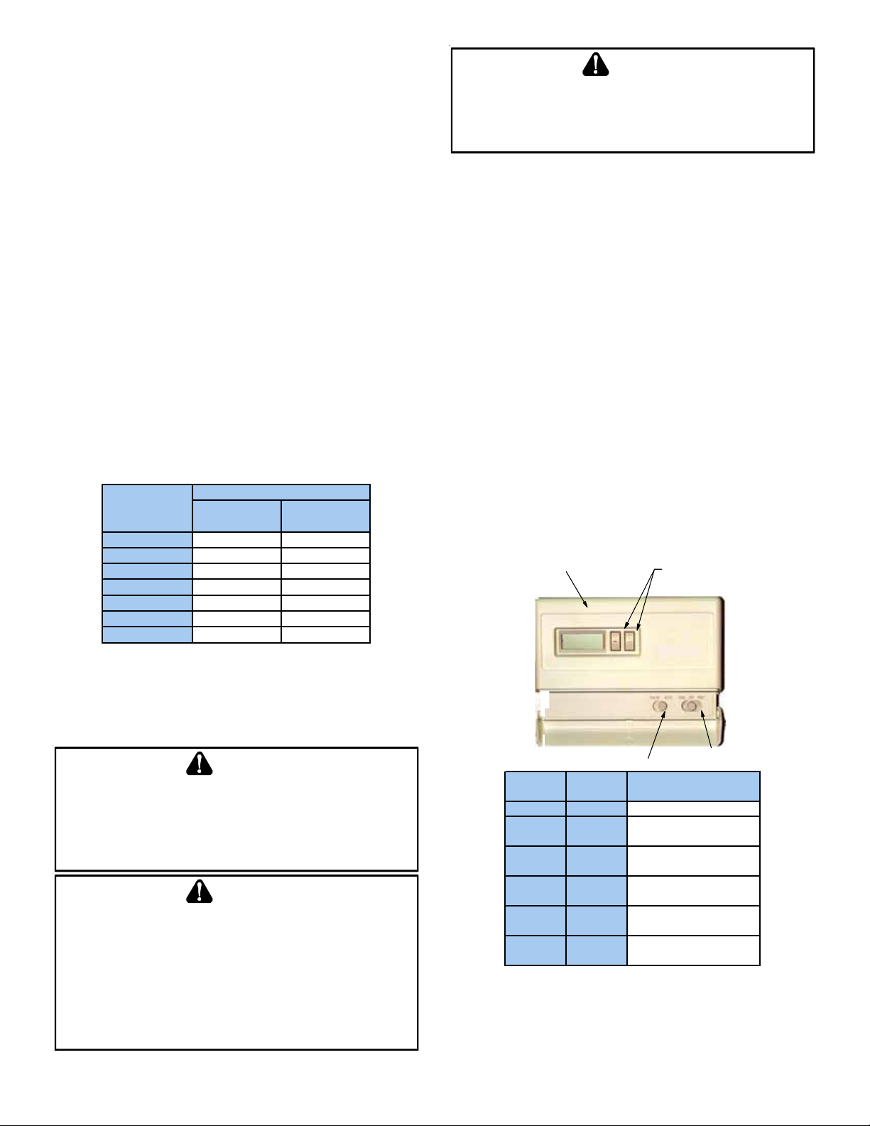
The following table shows the recommended maximum indoor humidity in relationship to the outdoor temperatures.
Outdoor Humidity
Temperature Single -Paned Double-Paned
Glass Glass
+30°F 30% 50%
+20°F 20% 40%
+10°F 15% 35%
0°F 10% 30%
-10°F 5% 25%
-20°F 5% 20%
-30°F 3% 18%
WARNING
AN
UNDETECTEDGASLEAKWILLCREATEADANGEROFEXPLOSIONOR
FIRE
.IF
THEPRESENCEOFGASISSUSPECTED,FOLLOWTHE
INSTRUCTIONSONTHECOVEROFTHISMANUAL
COULDRESULTIN
T
HERMOSTAT FUNCTIONS
SERIOUSPERSONALINJURYORDEA TH.
.F
AILURETODOSO
There are many types and styles of thermostats but operation is usually similar. BE SURE TO BECOME FAMILIAR WITH
YOUR THERMOSTAT. The simplest type of thermostat only
starts and stops the furnace to maintain the desired room
temperature. The most widely used types will control both
heating and cooling functions and will have a Fan Switch
with Auto and ON settings. On Auto, the circulating air
blower will cycle on/off with the furnace but if switched
to ON it will run continuously regardless of whether or not
heating or cooling is being provided.
In addition, there are thermostats which automatically
switch from heating to cooling mode and those with night
set back capability. The night set back, or multiple set
back, type allows for a different temperature at night or
during the day when no one is at home. Programmable
thermostats will allow for more control and tailoring of the
heating and cooling functions. The level of this control
depends on the type of thermostat applied.
Room Temperature
Thermostat
Cool/Heat
Temperature
Control Dials
P
ROPANE
(LP) G
AS INSTALLATIONS
O
NLY
For furnaces operating on propane gas, please review the
following warnings before use.
WARNING
TO
AVOIDPROPERTYDAMAGE,PERSONALINJURYORDEATH,DUETO
EXPLOSIONORFIRE,INSTALLAGASDETECTINGWARNINGDEVICE
THEODORANTINPROPANEGASCANBEREDUCEDBYIRONOXIDE
(
RUST
),A
GASDETECTINGWARNINGDEVICEISTHEONLYRELIABLE
METHODTODETECTPROPANEGASLEAKS
.
.S
INCE
WARNING
IF
THEGASFURNACEISINSTALLEDINABASEMENT,ANEXCAVATED
AREAORCONFINEDSPACE,ITISSTRONGLYRECOMMENDEDTO
CONTACTAPROPANESUPPLIERTOINSTALLAGASDETECTINGWARNING
DEVICEINCASEOFAGASLEAK
S
INCEPROPANEGASISHEAVIERTHANAIR,ANYLEAKINGGASCAN
•
SETTLEINANYLOWAREASORCONFINEDSPACES
•
ROPANEGASODORANTMAYFADE,MAKINGTHEGASUNDETECTABLE
P
EXCEPTWITHAWARNINGDEVICE
.
.
.
Fan Switch
System
Switch
OFF AUTO
COOL AUTO
COOL ON
HEAT AUTO
HEAT ON
OFF ON
Fan
Switch
None
System only cools, fan
cycles off and on.
System only cools, fan
runs all the time.
System only heats, fan
cycles off and on.
System only heats, fan
runs all the time.
No heating or cooling,
fan runs all the time.
Cool/Heat
Action
Switch
5
Page 6
F
URNACE
O
PERATION
WARNING
E
LECTRICALCOMPONENTSARECONTAINEDINBOTHCOMPARTMENTS
T
OAVOIDPERSONALINJURY,ELECTRICALSHOCKORDEATH,DONOT
REMOV EANYINTERNALCOMPARTMENTCOVERS
QUALIFIEDSERVICERATONCEIFANABNORMALCONDITIONISNOTICED
Keep both doors in place except for inspection and maintenance. An interlock switch prevents furnace operation if
the blower door is not in place.
.C
ONTACTA
.
.
FURNACE START-UP
1. Close the external manual gas shut-off valve.
2. Turn off the electrical power to the furnace.
3. Set the room thermostat to the lowest possible setting.
4. Remove the burner compartment door.
5. This furnace is equipped with an ignition device which
automatically lights the burner. Do not try to light the
burner by hand.
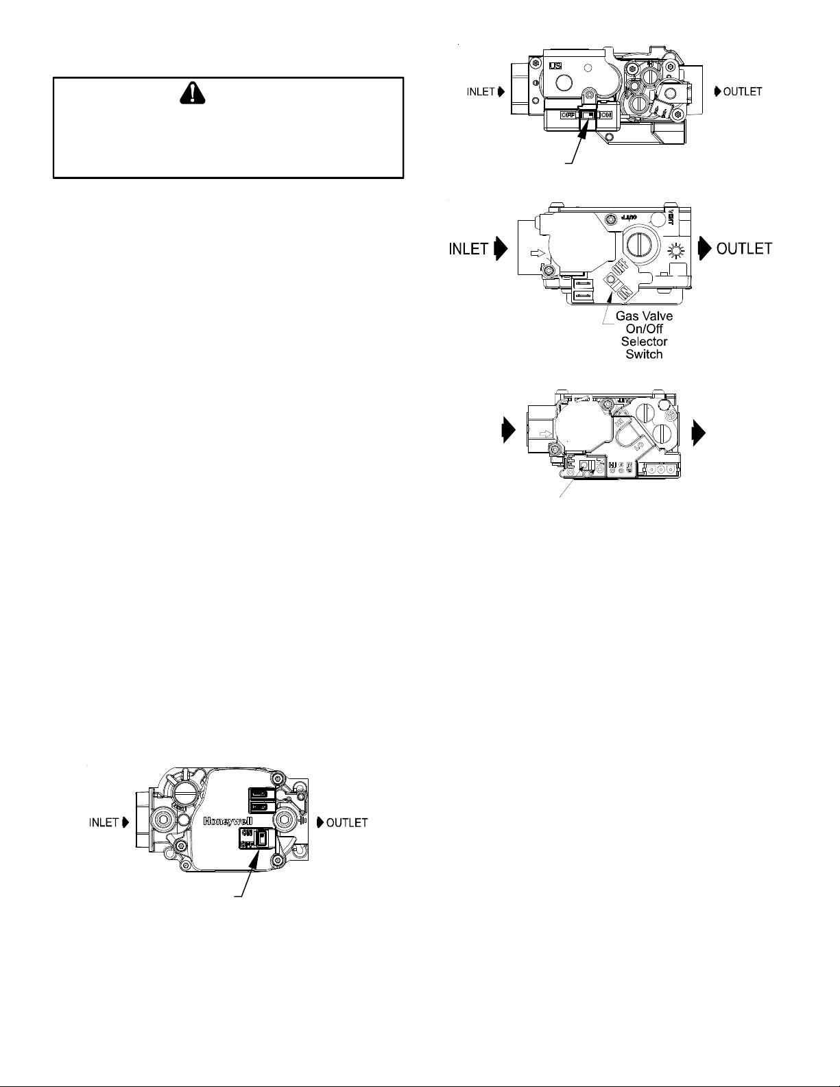
6. Move the furnace’s gas valve ON/OFF switch to the
OFF position.
7. Wait five minutes to clear out any gas. Then smell for
gas, including near the floor as some types of gas are
heavier than air.
8. If you smell gas following the five minute waiting period in step 7, immediately follow the instructions on
the cover of this manual. If you do not smell gas after
five minutes, move the furnace’s gas valve ON/OFF
switch to the ON position.
9. Replace the burner compartment door.
10. Open the external manual gas shut-off valve.
11. Turn on the electrical power to the furnace.
12. Adjust the thermostat to a setting above room temperature.
13. After the burners are lit, set the thermostat to desired
temperature.
Gas Valve On/Off
Selector Switch
Honeywell Model VR9205 (Two-Stage)
White-Rodgers Model 36G22 (Single-Stage)
INL E T
On/Off Sw itch
White-Rodgers Model 36G54 (Two-Stage)
OUTLET
FURNACE SHUT DOWN
To shut down your furnace, follow the steps listed below.
1. Set the thermostat to the lowest setting.
2. Integrated control closes gas valve extinguishing flame.
3. Induced draft blower is de-energized following a 15 second delay. The circulator blower is de-energized following a 90, 120, 150, or 180 second delay period.
4. Remove the burner compartment door.
5. Move the furnace’s gas valve ON/OFF switch to the OFF
position.
6. Close the external manual gas shut-off valve.
7. Replace the burner compartment door.
Gas Valve On/Off
Selector Switch
Honeywell Model VR8215 (Single-Stage)
LOCKOUT RESET
Furnace lockout is characterized by a non-functioning furnace (circulator blower may be running continuously) providing a diagnostic LED code. Lockout results when a furnace control detects abnormal conditions. If the furnace
is in “lockout”, it may be reset by any of the following
methods:
1. One hour automatic reset. Control will automatically
reset itself and attempt to resume normal operations
following a one hour lockout period.
6
Page 7
2. Power interruption. Interrupt 115 volt power to the furnace for greater than 20 seconds.
3. Thermostat cycle. Interrupt thermostat signal to the
furnace for between 0 and 20 seconds.
If the condition which originally caused the lockout still
exists, the control will return to lockout. If your furnace
frequently locks out, a problem exists which must be corrected. Contact a qualified servicer.
R
OUTINE
M
AINTENANCE
Maintenance is to be performed by a qualified service technician only. User maintenance is to be restricted to frequent air filter changes and to ensure the warnings and
notices found elsewhere in this manual be followed. We
recommend that at a minimum system maintenance be
performed by a qualified service technician prior to the
beginning of each heating season, and if equipped with air
conditioning, prior to air conditioning season.
WARNING
P
ERSONALINJURYORDEATHMAYRESULTFROMIMPROPER
MAINTENANCEPERFORMEDBYUNTRAINEDPERSONNEL
INSTALLINGDEALEROROTHERQUALIFIEDSERVICECOMPANIESTO
PERFORMTHEMAINTENANCEINSPECTION
.
.C
ALLYOUR
WARNING
TO
PREVENTPERSONALINJURYORDEATHDUETOELECTRICSHOCK
DISCONNECTELECTRICALPOWERBEFORESERVICINGTHISUNIT
,
.
ANNUAL INSPECTION
The furnace should be inspected by a qualified installer, or
service agency at least once per year. This check should be
performed at the beginning of the heating season by a qualified technician. This will insure that all furnace components are in proper working order and that the heating system functions appropriately. Particular attention should
be paid to the following items. Repair or service as necessary.
• Combustion air intake pipe system (where applicable).
Check for blockage and/or leakage. Check the outside
termination and the connection at the furnace.
• Heat exchanger. Check for corrosion and/or buildup
within the heat exchanger passageways.
• Burners. Check for proper ignition, burner flame, and
flame sense. Flames should extend directly outward
from burners without curling, floating or lifting off.
• Wiring. Check electrical connections for tightness and/
or corrosion. Check wires for damage.
• Drainage system. Check for blockage and/or leakage.
Check hose connections at and internal to furnace.
• Filters. Check that filters are clean and in the proper
placement in the furnace or duct system.
MOTORS
The combustion air motor and indoor blower motor are permanently lubricated and require no further lubrication.
FILTERS
WARNING
TO
AVOIDPROPERTYDAMAGE,PERSONALINJURYORDEATH
DISCONNECTELECTRICALPOWERBEFOREREMOV INGFILTERSOR
PERFORMINGANYOTHERMAINTENANCE
WITHOUTAFILTERINSTALLEDBECAUSEDUSTANDLINTWILLBUILDUP
ONINTERNALPARTSRESULTINGINLOSSOFEFFICIENCY,EQUIPMENT
DAMAGEORPOSSIBLEFIRE
.
.N
EVEROPERATEFURNACE
A return air filter is not supplied with this furnace and cannot be installed inside the cabinet; however, a means of
filtering all of the return air (intake) must be provided.
Your installer will supply filters at the time of installation.
Become familiar with filter location and procedures for removing, cleaning and replacing them.
If you need assistance, contact the installer of your furnace or another qualified servicer.
Filters must be inspected, cleaned or changed every two
months or as required. As a homeowner, it is your personal
responsibility to keep air filters clean. Remember that dirty
filters are the most common cause of inadequate heating
or cooling performance.
,
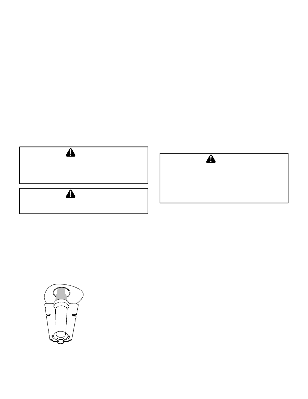
Check the
Burner Flames for:
1. Stable, soft and blue.
2. Not curling, floating
or lifting off.
• Flue pipe system. Check for blockage and/or leakage.
Check the outside termination and the connections at
and internal to the furnace.
FILTER REMOVAL
Depending on the installation, differing filter arrangements
can be applied. Filters can be located in a central return
grille or a side panel external filter rack (upflow only). To
remove filters from an external filter rack, follow the directions provided with external filter rack kit.
7
Page 8

HORIZONTAL UNIT FILTER REMOVAL
T
ROUBLESHOOTING
/ B
EFORE YOU REQUEST A SERVICE CALL
Filters in horizontal installations are located in the central
return register or the ductwork near the furnace.
To remove:
1. Turn OFF electrical power to furnace.
2. Remove filter(s) from the central return register or
ductwork.
3. Replace filter(s) by reversing the procedure for removal.
4. Turn ON electrical power to furnace.
To remove all other filter configurations, consult with the
installing contractor.
MEDIA AIR FILTER OR ELECTRONIC AIR CLEANER REMOVAL
High efficiency filters are available in both electronic and
non-electronic types. These filters can do a better job of
catching small airborne particles. Contact your dealer for
further information.
If using a Media or Electronic Air Cleaner, follow the directions provided with the air cleaner for proper filter removal,
cleaning, and replacement.
FILTER CLEANING AND/OR REPLACEMENT
Disposable filters must be replaced with a filter or filters
of the same size as that which is removed. Filters must
comply with UL900 or CAN/ULC-S111 Standards.
Permanent filters must be cleaned, washed, and dried as
specified by the filter manufacturer. If it becomes necessary to replace a permanent filter , it must be replaced with
a filter or filters of the same size as that which is removed.
Filters must comply with UL900 or CAN/ULC-S111 Standards.
If your furnace is not operating or is performing improperly, take time to perform the following checks before requesting service. A couple of simple checks may allow you
to avoid a service call. If the following steps do not resolve
the problem, contact a qualified servicer for further troubleshooting and/or repairs. Do not attempt troubleshooting
beyond that which is outlined in the following bullet points.
Do not attempt repairs yourself.
• Check the blower compartment sight glass. If LED is
flashing, record the number of flashes seen in sequence,
shutdown your unit as outlined in the “Furnace Startup” section and contact a qualified servicer for further
troubleshooting and/or repairs. Refer to Installation
Instructions for code identification. If not flashing,
continue with checks.
• Check thermostat for proper operation. Verify that it
is set on HEA T and that temperature (above room temperature) setting is appropriate.
• Check the electrical panel for tripped circuit breakers
or failed fuses. Reset the circuit breakers or replace
fuses as necessary.
• Check to see that the manual gas shut-off valve external to the furnace is in the ON position. If the valve is
in the OFF position, turn the gas ON following the start
up procedures outlined in the “Furnace Start-up” section.
• Check for dirty filter(s). This in the most common cause
of improper furnace operation. Check your filter(s) at
least once a month and replace or clean filters as necessary.
• Check for blocked return air or supply air grilles throughout your home. Grilles may be blocked by furniture,
drapery, clothes, carpeting, etc. Clear any blockage.
• Check intake and vent terminations on high efficiency
furnaces to make sure they are not blocked.
When reinstalling filters, be careful to maintain correct
airflow direction.
8
Page 9
S
AFETY
L
ABELS
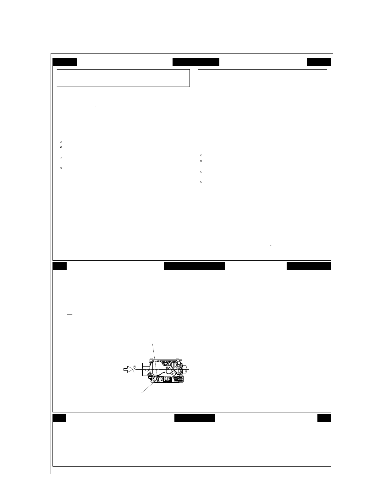
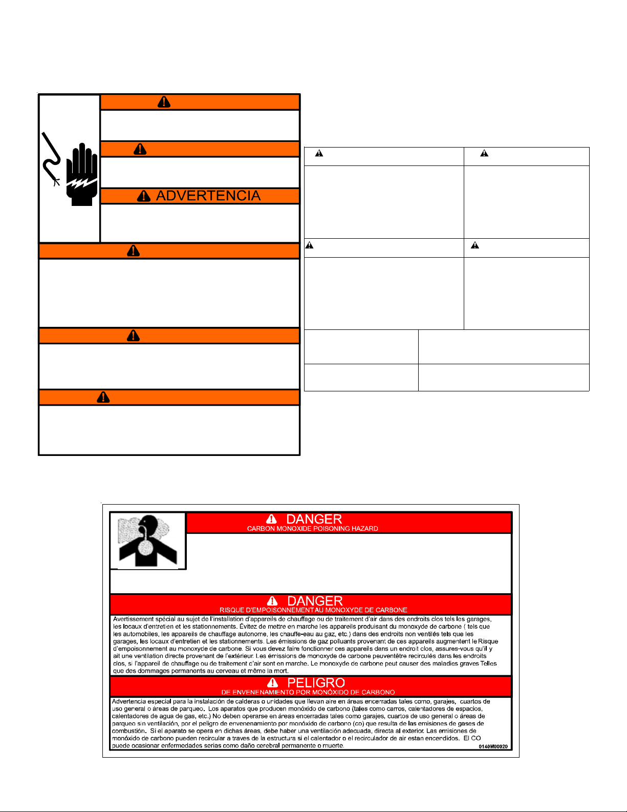
NOTE: If safety labels are missing or illegible, contact the installing dealer or our Customer Service Department for
ordering information.
FOR YOUR SAFETY
READ BEFORE OPERATING
If you do not follow these instructions
WARNING:
explosion may result causing propertyexac tly ,a fire o r
damage, personal injury or
loss of life.
A. This appliance does not have a pilot. It is equi pped
with an ignition device which automatically lights
the burner. Do not try
to light the burner by hand.
B. smell all around the appliance
BEFORE OPERATING
area for gas. Be sure to smell next to the floor
because some gas is heavier than air and will
settle on the floor.
WHAT TO DO IF YOU SMELL GAS
Do not try to light any appliance.
Do not touch any electr i c switch;
do not use any phone in your building.
Immediately call your gas supplier from a neighbor' s
phone. Follow the gas supplier's instructions.
If you cannot reach your gas supplier,
call the fire department.
C. Use only your hand to pus h i n or turn the gas control lever.
Never use tools. If the lever will not push in or turn by
hand, don't try to repair it, call a qualified service
technician. Fo r ce or at te mpt ed r epa ir m ay r esu l t in a fire
or explosion.
D. Do not use this appl i ance if any part has been under water.
Immediately call a qualified service technician to inspect
the appliance and to replace any part of the control
system and any gas control which has been underwater.
AVERTISSEMEN T:
la lettre les instructions dans le presént manuel
risque de déclencher un incendie ou une explosion
entraînant des dommages matériels, des lesions
corporelles ou la pert e de v i es humaines.
Cet appareil ne comporte pas de veilleuse . Il est
A.
muni d'un dispos i tif d'allumage qui allume
automatiqu ement le brûleur. Ne pas tenter
d'allumer le brûleur manuel l ement.
B. AVANT DE LE FAIRE FONCTIONNER,
renifler to ut autour de l'appariel pour decéler
une odeur de gaz. Renifler prés du plancher, car
certains gaz s ont plus lourds que l'air et
peuvent s'accumuler au nivea u du s ol.
QUE FAIRE S'IL Y A UNE ODEUR DE GAZ
Ne pas tenter d'allumer d'appareils.
Ne touche r à aucun interr upteur; ne pas vous servir
des téléphones dans le bâtiment.
Appelez immédiatement votre fournisseur de gaz depuis
un voisi n. Suivez les i nstructions du fournisseur de gaz
Si vous ne pouvez rejoindre le fournisseur de gaz,
appelez le service de s i ncendies.»
C. Ne pousser ou tourner la manette d'admi ssion du gaz
qu'à la main. Ne jamais emploer d'outil à cette fin.
Si la manette res te coincée, ne tenter pas de l a
réparer; appelez un technic ien qualifié. Quiconque
tente de forcer la manette ou de l a réparer peut
provoquer une explosion ou un i ncendie.»
D. Ne pas se servir de cet appareil s' il a été pl ongé dans
l'eau, même partielleme nt . Fai r e insp ecter l'appareil
par un technicien qualifié et rem placer toutr partie du
systéme de contrôle et toute comm and e qui ont été
plongées dans l'eau.»
LIRE AVANT DE METTRE
EN MARCHELIRE
Quiconque ne respecte pas à
OPERATING INSTRUCTIONS
1. Read the safety information above on
STOP!
this label.
2. Set the ther m o sta t to lowe s t set ti ng .
3. Tur n off all electric p ower to the appliance.
4. This appliance is equipped with an ignition
device which automatically lights the burner.
Do not try to light the bur ner by hand.
5. Push the gas control lever to Position.
Do not force.
6. Wait five (5) minutes to clear out any gas. Then
smell for gas, including near the floor. If you
then smell gas, Follow
in the safety. information above
on this label i f you don't smell
gas, go to next step.
7. Push gas control lever
to
"ON".
8. Replace access panel.
9. Tur n on all elect ric
power to the appliance.
10. Set thermostat to desired settin g .
11. If the appliance will not operate,
follow the instructions "To Turn
Off Gas To Appliance" and call your
service techni cian or gas company.
STOP! "B"
"OFF"
GAS
INLET
ARRIVEE
DU GAZ
ROBINET A GAZ
MANUEL, EN POS
MANUAL GAS
LEVER SHOWN
IN "ON" POS
TO TURN OFF GAS TO APPLIANCE
1. Set the thermos tat to lowe st setting.
2. Tur n of f all electr ic pow er to the appliance
if service is to be performed.
3. Push the gas control lever to Position.
Do not fo rce.
4. Replace control access panel.
"OFF"
"ON/MARCHE"
MISE EN MARCHE
ARRÊTEZ
1. Lisez les instructions de sécurité dans la
section supérieure de cet te étiquette.
2. Régler le thermostat à la température la plus basse.
3. Couper l'alimentation électrique de l'appareil.
4. Cet appareil menager etant dote d'un systeme
d'allumage automatique, ne pas essayer à
allumer le brûleur manuellement.
5. Pousse l e l evier du contrÔle du gaz a
position.
6. Attendre cinq (5) minutes pour laisser echapper tout le
gaz. Renifler tout autour de l'appar e i l, y compris prés du
plancher, pour déceler une odeur de gaz . Si c'est l e cas,
Passer à l'etape B des instructions de securite
ARRÊTEZ.
sur la portion superieure de cette etiquette.
S'il n'y a pas d'odeur de gaz, passer à l'etàpe suivant e.
7. Pousse l e l evier du contrôle du gaz à
position.
8. Remettr e en place le pann eau d'accés.
9. Mettre l ' appareil sous tension.
10. Régler le thermostat à la tempéra ture désirée .
11. Si l'appareil ne se met pas en marche, suivre les
instructions intitulées Comment couper l'admission
de gaz de l'appareil et appeler un technicien
qualifié ou l e fournisseur de gaz.
"OFF/ ARRET"
"ON/MARCHE”
POUR COUPER L'ADMISSI ON
DE GAZ DE L'APPAREIL
1. Régler le thermostat à la température la plus bassé.
2. Couper l'alimentation électrique de l'appareil s'il
faut procéder à des operations d' entretien.
3. Pousse le levier du contrôl e du gaz à
position.
Ne pas forcer.
4. Remettre en place le panneau d'accés.
"OFF/ AR RET"
0140F00000P R E V C
9
Page 10
S
AFETY
L
ABELS
RISK OF ELECTRIC SHOCK. CAN CAUSE INJURY OR DEATH:
DISCONNECT ALL REMOTE ELECTRIC POWER SUPPLIES
BEFORE SERVICING. THIS COMPARTMENT MUST BE CLOSED
EXCEPT WHEN SER VICING.
A VERTISSEMENT
WARNING
DANGER DE CHOC É LETRIQUE O U DE M ORT. COUPEZ TOUT LE
COURANT AVANT TOUT ENTRETIEN OU RÉPARATION. LE
COMPARTEMENT DOIT RESTER FERMER SAUF PENDANT
LÉNTRETIEN.
PELIGRO DE CHOQUE ELÉCTRICO O MUERTE. DESCONECTE
TODAS LAS FUENTES DE ENERGÌA ELÉCTRICA ANTES DE
MANTENIMIENTO O SERVICO TÉCNICO. EL COMPARTIMIENTO
DEBE PERMANECER CERRADO EXCEPTO DURANTE EL
SERVICIO DE MANTENIMIEN TO.
WARNING
HEATING UNITS SHOULD NOT BE UTILIZED WITHOUT REASONABLE ROUTINE
INSPECTION , MAINTENA NCE, AND SUPERVISION . IF THE BUILDING IN WHICH ANY
SUCH DEVICE IS LOCATED WILL BE VACANT, CARE SHOULD BE TAKEN THAT SUCH
DEVICE IS ROUTINELY INSPEC TED, MAINTAINED, AND MONITORED. IN THE EVE NT
THAT THE BUILDING IS EXPOSED TO FREEZING TEMPERATURES, ALL WATER-BEARING
PIPES SHOULD BE DRAINED,THE BU ILDING SHOULD BE PROPERLY WINTERIZED, AND
THE WATER SOURCE C LOSED . SHOU LD THE BUILD ING BE EXPOSED TO FREEZING
TEMPERATURES, ANY HYDRONIC CO IL UNITS SH OU LD BE DRA I NE D AS WELL; AND, IN
SUCH CASE, AL TERNAT IVE HEAT SOURCES SHOUL D BE UTILIZED.
WARNING
IMPROPER ADJUSTM EN T, ALTE RATION, SERV ICE , MAINT EN AN C E OR INSTALLATION
CAN CAUSE SERIOUS INJURY OR DEATH.
READ AND FOLLOW INST RUCTIONS AND PRECAUTIO N S IN USER ’S INFOR MATION
MANUAL PROVIDED WITH THIS FURNACE. INSTALLATION AND SERVICE MUST BE
PERFORMED BY A QUALIFIED SERVICE AGENCY OR GAS SUPPLIER.
FIRE, EXPLOSION, AND ASPHYXIATION HAZARD
A VERTISSEMENT
UN RÉGLAGE, UN E MOD IFICATION, UNE RÉPARATION, UN ENTRETIEN OU UNE
INST AL LATION INC ORRECTE PEUT ENTRAINER DES BLE SSURES GRAVES OU LA
MORT. SUIVEZ LES INSTRUCTIONS ET LES CO NSIGNES DANS LA NOTICE
D’UTIL ISATION QUI AC COM PAGNE CE GÉNÉRA TEUR D’AIR CHA UD . L’INSTALLAT IO N
ET L’ENTRETIEN DOIVENT ÊTRE EFFECTUES PAR UN RÉPARATEUR QUALIFIÉ OU PAR
LE FOURNISSEUR DE GAZ
RISQUE D’INCENDIE ET D’ASPHYXIE
0140M00010
WARNING: FIRE, EXPLOSION AND
IMPROPER INSTALLATION, ADJUSTMENT, ALTERATION
SERVICE OR MAINTENANCE CAN CAUSE PROPERTY
DAMAGE, PERSONAL INJURY OR DEATH, OR EXPOSURE TO
SUBSTANCES IN FUEL OR FROM FUEL COMBUSTION WHICH
CAN CAUSE DEATH OR SERIOUS ILLNESS, AND WHICH ARE
KNOWN TO THE STATE OF CALIFORNIA TO CAUSE CANCER,
BIRTH D E FECTS, OR O THER REPRODUCTIVE HARM. READ
AND FOLLOW INSTRUCTIONS AND PRECAUTIONS IN USER'S
INFORMATION MANUAL PROVIDED WITH THIS FURNACE.
INSTALLATION AND SERVICE MUST BE PERFORMED BY A
QUALIFI ED INSTALL ER , S ERVICE AGENCY OR GAS
SUPPLIER.
UN REGLAGE, UNE MODIFICA TIO N, UN RÉPARATI ON, UN
ENRETIEN OU UNE INSTALLATION INCORRECT PUET
ENTRAÎNER DES BLESSURES GRAVES OU LA MORT.
SUIVRE LES INSTRUCT ION ET LES CONSIGNES Q UI
FIGURENT DANS LA NOTICE D'UTILISATION QUI
ACCOM PA GNE CE GÉNÉ RATEUR D'AIR CHAUD.
L'INSTALLATION ET L'ENTRETIEN DOIVENT ÊTRE
EFFECTURÉS PAR UN RÉPARATEUR QUALIFIÉ OU PAR LE
FOURNISSEUR DE GAZ .
SEE INSIDE SURFACE OF BURNER
COMPARTMENT DOOR FOR
LIGHTING/OPERATING INSTRUCTIONS.
LES INDICA TIONS POUR L 'ECLAI RAGE ET
LE SERVICE SE TROUVENT A LA
SURFACE INTERIEURE LA PORTE DU
COMPAR TIMENT DU B RULEUR.
ASPHYXIATION HAZARD
AVERTISSEMENT: RISQUE D'INCENDIE,
D'EXPLOSION ET ASPHYXIE
FILTER(S) SHOULD BE INSPECTED FREQUENTLY AND CLEANED
WHEN NECESSARY. WHEN REPLACEMENT IS REQUIRED BE
SURE TO USE THE SAME TYPE (CLASS 1 OR 2) AND SIZE
ORIGINALLY IN STALLED AND THAT IT IS U.L. C.* CERTIFIED.
*CANADIAN REQUIREMENT
LES FILTRES DOIVENT ETRE FREQUEMMENT INSPECTES ET
NETTOYES SI NECESSAIRE. REMPLACES-LES DE FILTRES DU
MEME TYPE (CLASSE 1 OU 2) ET FORMAT QUE DANS
L'EQUIPEMENT ORIGINAL. CERTIFIES PAR LE U.L.C. 22317001
WARNING: FIRE AND
EXPLOSION HAZARD
CAN RESULT IN SERI OU S IN JU RY OR DEATH.
DO NOT STORE OR USE GASOLINE OR OTHER
FLAMMABLE VAPORS AND LIQUIDS IN THE
VICINITY OF THIS OR ANY OTHER APPLIANCE.
STORAGE OF OR USE OF GASOLINE OR
OTHER FLAMMABLE VAPORS OR LIQUIDS IN
THE VICINITY OF THIS OR ANY APPLIANCE
CAN RESULT IN SERI OU S IN JU RY OR DEATH.
AVERTISSEMENT:RISQUE
D'INCENDIE ET D'EXPLOSION
RISQUE DE BLESSURES GRAVES OU DE
MORT. NE PAS ENTREPOSER NI UTILISER DE
L'ESSENCE NI D'AUTRES VAPEURS OU
LIQUIDES INFLAMMABLES DANS LE
VOISINAGE DE CET APPAREIL, NI DE TOUT
AUTRE APPAREIL. LE FAIT D'ENTREPOSER OU
D'UTILISER DE L'ESSENCE OU D'AUTRES
LIQUIDES OU VAPEURS INFLAMMABLES À
PROXIMITÉ DE CET APPAREIL OU DE TOUT
AUTRE APPAREIL PEUT CAUSER DES
BLESSURES GRAVES OU LA MORT.
Special warning for installation of furnaces or air handling units in enclosed area such as garages, utility
rooms or parking areas. Carbon m onoxide producing devices (such as an automobile, space heater, gas
water heater, etc.) Should not be operated in enclosed areas such as unventilated garages, utility room or
parking areas because of the danger of carbon monoxide (CO) poisoning resulting from the exhaust
area and a carbon monoxide producing device is operated therein, there must be adequate, direct outside ventilation. Carbon monoxide
emissions can be (re)circulated throughout the structure if the furnace or air handler is operating in any mode. CO can cause serious
illness including permanent brain damage or death.
emissions. If a furnace or air handler is installed in an enclosed area such as garage, utility room or parking
10
Page 11

THIS PAGE LEFT INTENTIONALLY BLANK
11
Page 12

Most questions can be answered by your local dealer. For additional information, please call:
CONSUMER INFORMATION LINE
TOLL FREE
1-877-254-4729 (U.S. only)
email us at: [email protected]
fax us at: (731) 856-1821
(Not a technical assistance line for dealers.)
Outside the U.S., call 1-713-861-2500.
(Not a technical assistance line for dealers.)
Your telephone company will bill you for the call.
To obtain the proper labels, the Model Number and Serial Number of the unit must be
supplied. These numbers are recorded on the nameplate of the furnace. For convenience, record this information here:
MODEL NUMBER: _ _ _ _ _ _ _ _ _ _ _ _ _
12
©
2004-2006, 2010, 2012 Goodman Company, L.P.
Effective: 02/12
 Loading...