

Goodman ASZC180481A, DSZC180361A, ASZC180601A, ASZC180601B, DSZC180481A Technical Manual
...
TECHNICAL MANUTECHNICAL MANU
TECHNICAL MANU
TECHNICAL MANUTECHNICAL MANU
ALAL
AL
ALAL
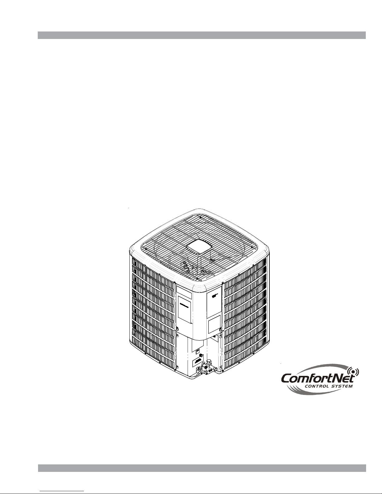
*SZC 18 SEER
Split System Heat Pump s
• Refer to Service Manual RS6200006 for installation, operation, and troubleshooting information.
• All safety information must be followed as provided in the Service Manual.
• Refer to the appropriate Parts Catalog for part number information.
• See models on page 3.
This manual is to be used by qualified, professionally trained HVAC technicians only. Goodman does
not assume any responsibility for property damage or personal injury due to improper service
procedures or services performed by an unqualified person.
Copyright © 2009 - 2010, 2012 - 2014 Goodman Manufacturing Company, L.P.
RT6214006r6
February 2014
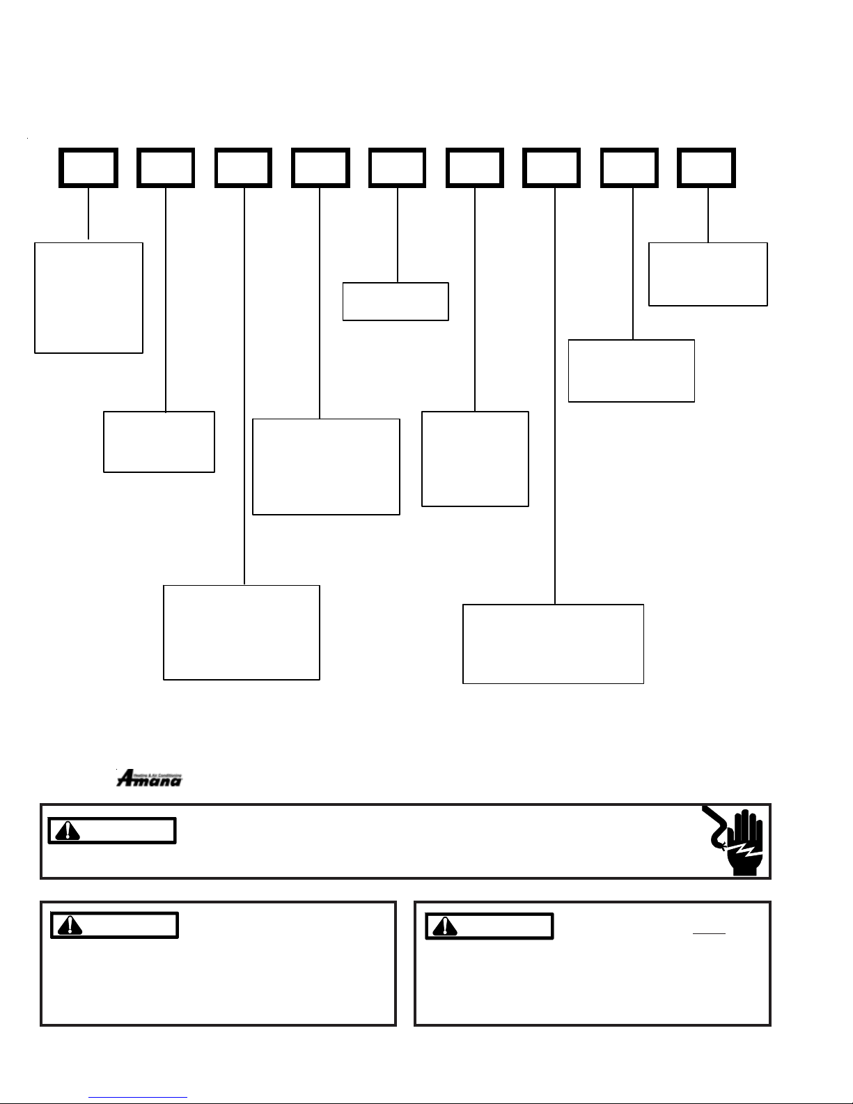
PRODUCT IDENTIFICATION
The model number is used for positive identification of component parts used in manufacturing. Please use this number
when requesting service or parts information.
D S Z C 18 036 1 A A
BRAND:
D: D eluxe
Go odman®
Brand
A: Aman a®
Brand
PRODUCT
FAMILY:
S: Spl it Syst em
COMMUNICATION
FEATURE:
C: 4-wir e
Communi cation
Ready
PRODUCT TYPE:
C: Condenser R-22
H: H eat Pump R - 2 2
X: Condenser R-410A
Z: Heat P u m p R-41 0A
SEER:
SEER Rating
NOMINAL
CAPACITY:
036: 3 T ons
048: 4 T ons
060: 5 T ons
MINOR
REVISION:
A: I nitia l Release
MAJOR
REVISION:
A: Init ial Release
ELECTRICAL:
1: 208-230V/1ph/ 60Hz
3: 208-230v/3p h/60Hz
4: 460v/3ph/60 Hz
is registered trademark of Maytag Corporation or its related entities and is used under license. All rights reserved.
HIGH VOLTAGE!
WARNING
WARNING
WARNING
WARNING
arising from improper service or service procedures. If
you install or perform service on this unit, you assume
responsibility for any personal injury or property damage
which may result. Many jurisdictions require a license to
install or service heating and air conditioning equipment.
2
Disconnect ALL power before servicing or installing this unit. Multiple power
sources may be present. Failure to do so may cause property damage, personal
injury or death.
Goodman will not be responsible
for any injury or property damage
WARNING
WARNING
ments of an "entry level technician", at a minimum, as
specified by the Air-Conditioning, Heating, and Refrigeration Institute (AHRI). Attempting to install or repair this
unit without such background may result in product
damage, personal injury or death.
Installation and repair of this unit
should be performed
individuals meeting the require-
ONLY by
PRODUCT IDENTIFICATION
The model number is used for positive identification of component parts used in manufacturing. Please use this number
when requesting service or parts information.
ASZC180361A*
ASZC180481A*
ASZC180601A*
ASZC180601B*
* Indicates minor revision & is not used for order entry or inventory management
DSZC180361A*
DSZC180481A*
DSZC180601A*
DSZC180601B*
WARNING
WARNING
WARNING
WARNING
Serious property damage, personal injury, reduced unit
performance and/or hazardous conditions may result
from the use of such non-approved devices.
The United States Environmental Protection Agency (“EPA”) has issued various regulations regarding the introduction and disposal of refrigerants introduced into this unit. Failure to follow
these regulations may harm the environment and can lead to the imposition of substantial fines.
These regulations may vary by jurisdiction. Should questions arise, contact your local EPA office.
Do not connect or use any device
that is not design certified by
Goodman for use with this unit.
WARNING
WARNING
do not store combustible materials or use gasoline or
other flammable liquids or vapors in the vicinity of this
appliance.
To prevent the risk of property
damage, personal injury, or death,
3
PRODUCT DESIGN
Models covered by this manual come with a new 4-wire communicating PCB. When paired with a compatible communicating indoor unit and a communicating thermostat, these
models can support 4-wire communication protocol and provide more troubleshooting information. These models are
also backward compatible with the legacy thermostat wiring.
*SZC18 models are available in 3, 4 and 5 ton sizes and
use R-410A refrigerant. They are designed for 208/230 volt
single phase applications.
The condenser air is pulled through the condenser coil by a
direct drive propeller fan. This condenser air is then discharged out of the top of the cabinet.
These units are designed for free air discharge, so no additional resistance like duct work shall be attached.
The suction and liquid line connections on present models
are of the sweat type for field piping with refrigerant type copper. Front seating valves are factory installed to accept the
field run copper. The total refrigerant charge for a normal installation is factory installed in the condensing unit. *SZC
units are charged for the matching evaporator coil and a 15
foot refrigerant line set.
Systems should be properly sized by heat gain and loss
calculations made according to methods of the Air Conditioning Contractors Association (ACCA) or equivalent. It is
the contractors responsibility to ensure the system has adequate capacity to heat or cool the conditioned space.
*SZC models use high-efficiency Copeland® scroll "Ultratech"
compressors which are specifically desgined for R-410A refrigerant. There are a number of design characteristics which
are different from the scroll compared to the traditional reciprocating compressor.
"Ultratech" Series scroll compressors with Copeland
ComfortAlert diagnostics will not have a discharge thermostat. Some of the early model scroll compressors required
discharge thermostats.
Due to their design Scroll compressors are inherently more
tolerant of small quantities of liquid refrigerant.
NOTE: Even though the compressor section of a Scroll compressor is more tolerant of liquid refrigerant, continued
floodback or flooded start conditions may wash oil from the
bearing surfaces causing premature bearing failure.
"Ultratech" Series scroll compressors use "POE" or
polyolester oil which is NOT compatible with mineral oil based
lubricants like 3GS. "POE" oil must be used if additional oil
is required.
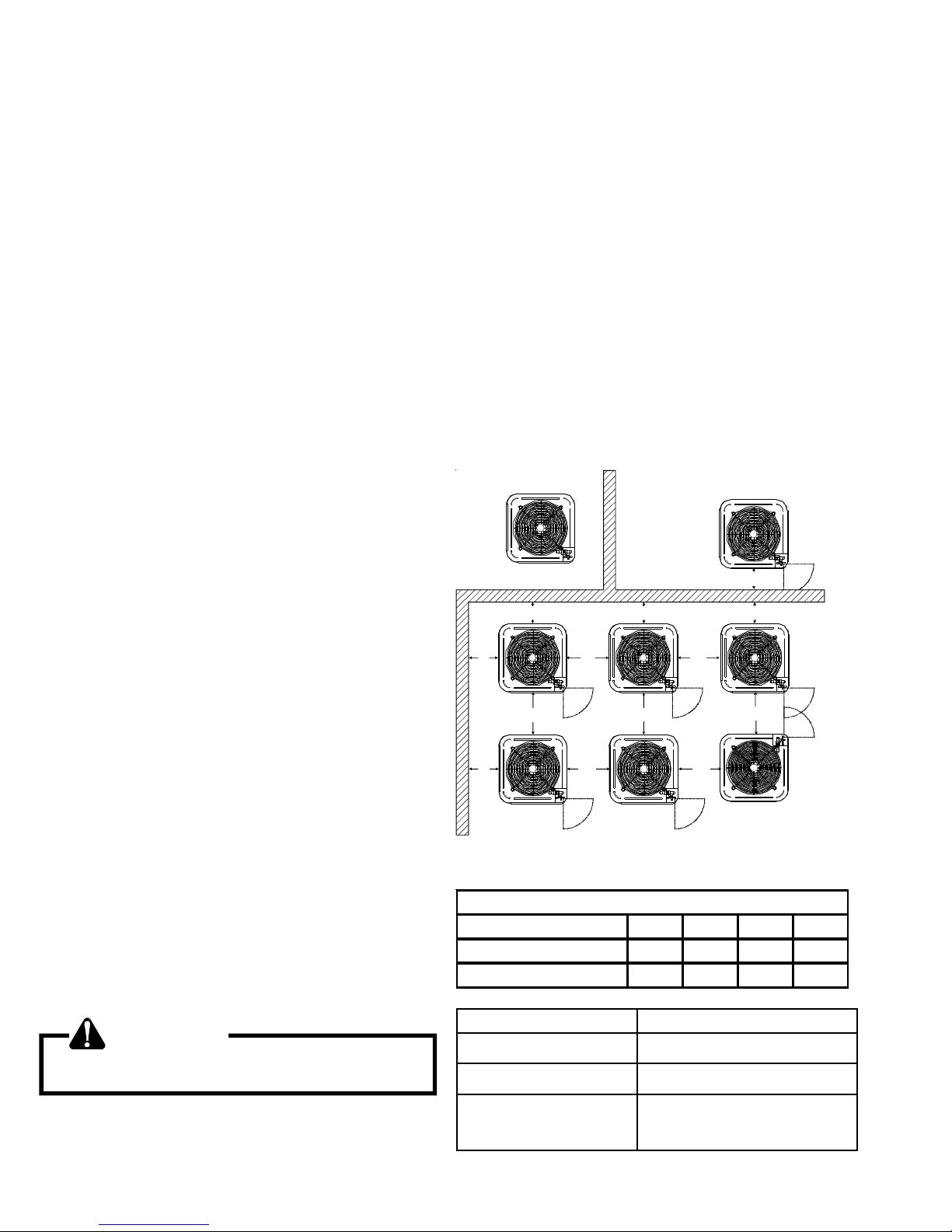
This unit is for outdoor installation only. Refer to figure for
minimum clearances from the sides of the unit to full walls
and other objects.
NOTE: This unit cannot be completely enclosed. At least
one side must be unrestricted.
These clearances will help avoid air recirculation. If installing
two or more units at the same location, allow at least 24
inches between units. If only one side is restricted (for example, against the outside wall of a house), the unit may be
placed as close as 8" to that one wall.
DO NOT locate the unit:
* Directly under a vent termination for a gas appliance.
* Within 3 feet of a clothes drier vent
* Where the refreezing of defrost water would create
a hazard
* Where water may rise into the unit.
NOT
RECOMMENDED
B B B
AA AAA
C
®
AA
A
AA
AA
C
AA
CC
B
AA
OK!
OK!
OK!
Minimum Air flow Clearance
Model Type A B C AA
Residential 10" 10" 18" 20"
Light Commercial 12" 12" 18" 24"
OK!
OK!
OK!
WARNING
To avoid possible injury, explosion or death, practice
safe handling of refrigerants.
Operating pressures and amp draws may differ from standard
reciprocating and/or scroll compressors. This information may
be found in the "Cooling Performance Data" section.
4
Model Dimensions - W x D x H
*SZC180361A* 35½ x 35½ x 38¼
*SZC180481A* 35½ x 35½ x 38¼
*SZC180601A*
*SZC180601B*
35½ x 35½ x 38¼

HEAT PUMP SPECIFICATIONS
*SZC180361A* - *SZC180481A*
*SZC180361A*
*SZC180361AD
*SZC180481A*
*SZC180481AD
Cool ing Capacity, BTUH 35,000 35,000 47,000 47,000
Compressor
R.L. Amps
L.R. Amps
16.7 15.3 21.2 21.2
82.0 83.0 96.0 104.0
Low Pressure Switch
Op en 22 + / - 7 PSIG 22 + / - 7 PSIG 2 2 + / - 7 PSIG 22 + / - 7 PSI G
Clo se 50 + / - 7 PSIG 50 + / - 7 PSIG 5 0 + / - 7 PSIG 50 + / - 7 PSI G
High Press ure Sw itch
Op en 610 PSIG 610 PSIG 610 PSIG 610 PSIG
Clo se 420 PSIG 420 PSIG 420 PSIG 420 PSIG
Condenser Fan Motor
Horsepower 1/3 1/3 1/3 1/3
F.L. Amps 2.8 2.8 2.8 2.8
Liquid Line, Inch es O.D.* 3/8" 3/8" 3/8" 3/8"
Suc t io n Line , In c hes O.D.* 7/8 " 7/8 " 1 1/ 8" 1 1/ 8"
Refrigerant Charge 188.0 188.0 278.0 278.0
Power Supply 208/230-60-1 208/230-60-1 208/230-60-1 208/230-60-1
Minimum Circuit Ampacity
Maximum Overcurrent Device
(1)
(2)
23.7 21.9 29.3 29.3
40 35 50 50
Electrical Conduit Size
Power Supply (In ches) 1/2 or 3/4 1/2 or 3/4 1/2 or 3/4 1/2 or 3/4
Approximate Shipping Weight
*
Up to 24' in equivalent line length
(1)
Wire size should be determined in accordance with National Electrical Codes; extensive wire runs will require larger wire sizes.
(2)
Maximum Overcurrent Protection Device: MUST use Time Delay Fuse or HACR type Circuit Breaker of the same size as noted.
268 268 330 330
NOTES:
• Always check the serial plate for electrical data on the unit being installed.
• Installer will need to supply 7/8" to 1-1/8" adapters for suction line connections (4 & 5 ton units).
• Installer will need to supply 3/4" to 7/8" adapters for suction line connections (3 ton unit).
• Unit is charged with refrigerant for 15' of 3/8" liquid line. System charge must be adjusted per Installation Instructions Final Charge
Procedure.
• Installation of these units requires the specified TXV Kit to be installed on the indoor coil. THE SPECIFIED TXV IS DETERMINED BY THE
OUTDOOR UNIT, NOT THE INDOOR COIL.
NOTE: This data is provided as a guide, it is important to electrically connect the unit and properly size fuses/circuit breakers and
wires in accordance with all national and/or local electrical codes. Use copper wire only.
Unit specifications are subject to change without notice. ALWAYS refer to the unit's serial plate for the most up-to-date general
and electrical information.
5
HEAT PUMP SPECIFICATIONS
*SZC180601A*
Co o li ng Ca p ac ity , BTUH 57,000
Compressor
R.L. Amps
L.R. Amps
Low Pressure Switch
Open 22 + / - 7 PSIG
Clo se 50 + / - 7 PS IG
High Pressure Switch
Open 6 10 PSIG
Clos e 420 P S IG
Co n den s er Fa n Mo to r
Horsepower 1/3
F.L. Amp s 2.8
Liquid L ine, Inches O.D.* 3/8"
Suc t ion Line, Inche s O.D .* 1 1/8
Refrigerant Char ge 278.0
Power S upp ly 208/230- 60-1
Mi n imum Cir cu it Ampa c it y
Maximum Overcur rent Device
Electrical Conduit Size
Power Supply (Inches) 1/2 or 3/4
Approximate S hipping Weight
(1)
(2)
*SZC180601A*
25.6
118.0
34.8
60
345
*
Up to 24' in equivalent line length
(1)
Wire size should be determined in accordance with National Electrical Codes; extensive wire runs will require larger wire sizes.
(2)
Maximum Overcurrent Protection Device: MUST use Time Delay Fuse or HACR type Circuit Breaker of the same size as noted.
NOTES:
• Always check the serial plate for electrical data on the unit being installed.
• Installer will need to supply 7/8" to 1-1/8" adapters for suction line connections (4 & 5 ton units).
• Installer will need to supply 3/4" to 7/8" adapters for suction line connections (3 ton unit).
• Unit is charged with refrigerant for 15' of 3/8" liquid line. System charge must be adjusted per Installation Instructions Final Charge
Procedure.
• Installation of these units requires the specified TXV Kit to be installed on the indoor coil. THE SPECIFIED TXV IS DETERMINED BY THE
OUTDOOR UNIT, NOT THE INDOOR COIL.
NOTE: This data is provided as a guide, it is important to electrically connect the unit and properly size fuses/circuit breakers and
wires in accordance with all national and/or local electrical codes. Use copper wire only.
Unit specifications are subject to change without notice. ALWAYS refer to the unit's serial plate for the most up-to-date general
and electrical information.
6
HEAT PUMP SPECIFICATIONS
*SZC180601B*
*SZC180601B*
*SZC180601BB
Cooling Capacity, BT U H 57,0 00 57, 00 0
Compressor
R. L. Amps
L.R . Amps
23.0 28.8
118.0 152.9
Low Pressure Switch
Ope n 22 + / - 7 PSIG 22 + / - 7 P SIG
Close 50 + / - 7 PSIG 50 + / - 7 PSIG
High Pressu r e Switch
Ope n 6 10 PSIG 610 PSIG
Clos e 420 PSIG 420 PSIG
Condenser Fan Motor
Horsepower 1/3 1/3
F.L. Amps 2.8 2.8
Liquid Line, In ches O.D.* 3/8" 3/8"
Suc t ion Line , In c hes O. D. * 1 1/8 1 1/ 8
Refrigerant Charge 278.0 278.0
Power Suppl y 208/ 230-60-1 208/ 230- 6 0-1
Minimum Circuit Ampacity
Maximum Overcurrent Device
(1)
(2)
31.6 38.8
50 60
Electrical Conduit Size
Power Suppl y (Inc hes) 1/2 or 3/ 4 1/ 2 or 3/4
Approximat e Shipping W eight
336 336
*
Up to 24' in equivalent line length
(1)
Wire size should be determined in accordance with National Electrical Codes; extensive wire runs will require larger wire sizes.
(2)
Maximum Overcurrent Protection Device: MUST use Time Delay Fuse or HACR type Circuit Breaker of the same size as noted.
NOTES:
• Always check the serial plate for electrical data on the unit being installed.
• Installer will need to supply 7/8" to 1-1/8" adapters for suction line connections (4 & 5 ton units).
• Installer will need to supply 3/4" to 7/8" adapters for suction line connections (3 ton unit).
• Unit is charged with refrigerant for 15' of 3/8" liquid line. System charge must be adjusted per Installation Instructions Final Charge
Procedure.
• Installation of these units requires the specified TXV Kit to be installed on the indoor coil. THE SPECIFIED TXV IS DETERMINED BY THE
OUTDOOR UNIT, NOT THE INDOOR COIL.
NOTE: This data is provided as a guide, it is important to electrically connect the unit and properly size fuses/circuit breakers and
wires in accordance with all national and/or local electrical codes. Use copper wire only.
Unit specifications are subject to change without notice. ALWAYS refer to the unit's serial plate for the most up-to-date general
and electrical information.
7
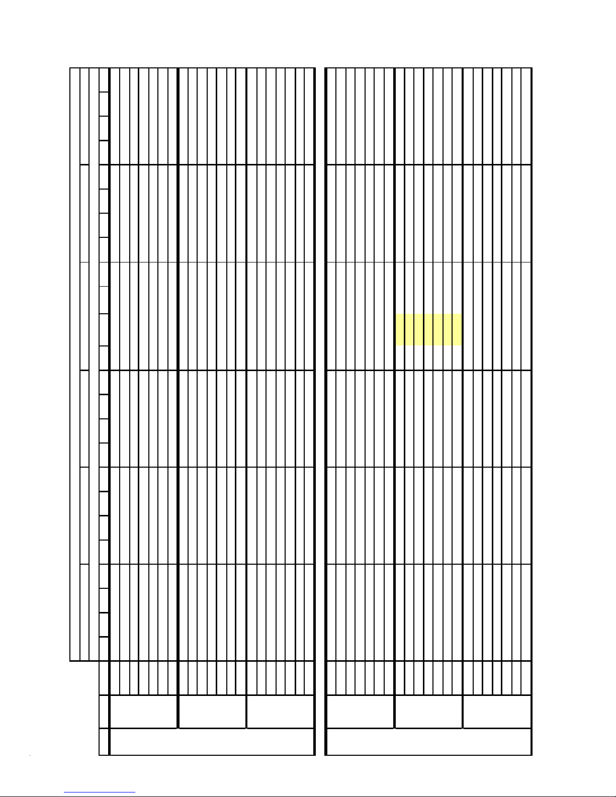
COOLING PERFORMANCE DA T A
5
5
5
w
3
3
7
9
-
-
-
-
-
-
A
-
-
-
-
R
-
-
-
-
-
-
-
-
A
-
-
-
-
R
-
-
-
-
-
-
-
-
A
-
-
-
-
R
-
-
A
6
R
A
8
R
A
9
R
g
63 67 71
*SZC180361A*-LOW ST AGE
18 16 12
7.2 7.4 7. 7
363 390 412
0.81 0.67 0.47
COOLING OPERATION
71 5
6
19 17 13
0.80 0.67 0.46
67 71 59 63 67 71 59 6
Outdoor Ambien t Temperature
85 95 105 11
Entering Ind oor Wet Bu lb Tempera ture
133 141 154
1.71 1.75 1.81
6.8 7.0 7.2
328 353 373
128 137 149
1.65 1.69 1.75
18 15 12
7.5 7.6 7. 9
374 402 425
0.84 0.70 0.48
19 17 13
0.83 0.69 0.48
137 146 159
1.76 1.80 1.86
7.0 7.2 7.5
338 364 384
132 141 154
1.69 1.73 1.79
17 15 11
7.5 7.7 8. 0
377 406 429
0.88 0.73 0.51
18 16 12
0.87 0.73 0.50
138 147 161
1.77 1.81 1.88
7.1 7.3 7.5
342 368 388
134 142 155
1.71 1.75 1.81
6.9 7.1 6.9 7.1 7.3 7.6 7.3 7.5 7.7 8.0
144 153 130 138 151 160 134 143 156 166
17 12 22 20 17 12 21 19 16 11
25.4 27.2 21.6 22.3 24.1 25.9 20.0 20.6 22.3 24.0
23 . 4
7.1 7.3 7.1 7.3 7.5 7.8 7.5 7.7 8.0 8.3
21
6.
7.1 7.4 7.2 7.3 7.6 7.9 7.6 7.8 8.0 8.4
7
EXPA N DED PERFO RMA NCE DATA
6
59 63 67 71 59 63 67 71 59 6
DT 19 17 13 - 20 17 13 - 20 17 13 - 20 17 13
S/T 0.70 0.59 0.41 - 0.73 0.61 0.42 - 0.75 0.62 0.43 - 0. 77 0.64 0.45
MBh 22.2 23.0 25.2 - 21.7 22.5 24.6 - 21.2 21.9 24.0 - 20.7 21.4 23.5 - 19.6 20.3 22.3 - 18.2 18.8 20.6 -
irflo
MODEL: *SZC180361A* / CA*F3743*6** + TXV / MBV C 1600**-1** Design Subcooling 5 - 7 °F @ the liquid service valve, AHRI 95° F test conditions
8
IDB*
106 113 123 - 112 119 130 - 117 124 135 - 123 130 142
DT 19 16 12 - 19 17 13 - 19 17 13 - 19 17 13
MPS 5.1 5.2 5.4 - 5.5 5.7 5.9 - 6.0 6.2 6.4 - 6.4 6.6 6.8
744 KW 1.29 1.32 1.37 - 1.40 1.43 1.48 - 1.50 1.53 1.58 - 1.58 1.61 1.67
S/T 0.73 0.61 0.42 - 0.76 0.63 0.44 - 0.78 0.65 0.45 - 0. 80 0.67 0.46
MBh 24.1 24.9 27.3 - 23.5 24.4 26.7 - 22.9 23.8 26.1 - 22.4 23.2 25.4 - 21.3 22.0 24.1 - 19.7 20.4 22.4 -
HI PR 201 216 228 - 225 242 256 - 256 276 291 - 292 314 331
LO P
110 117 127 - 116 123 134 - 120 128 140 - 126 134 147
DT 18 16 12 - 18 16 12 - 18 16 12 - 19 16 12
MPS 5.3 5.4 5.6 - 5.7 5.8 6.0 - 6.2 6.3 6.5 - 6.6 6.8 7.0
70 850 KW 1.33 1.36 1.40 - 1.44 1.47 1.52 - 1.54 1.57 1.63 - 1.62 1.66 1.72
S/T 0.77 0.64 0.44 - 0.79 0.66 0.46 - 0.81 0.68 0.47 - 0. 84 0.70 0.49
MBh 24.8 25.7 28.1 - 24.2 25.1 27.5 - 23.6 24.5 26.8 - 23.1 23.9 26.2 - 21.9 22.7 24.9 - 20.3 21.0 23.0 -
HI PR 207 223 235 - 232 250 264 - 264 284 300 - 301 324 342
LO P
111 118 128 - 117 124 136 - 121 129 141 - 128 136 148
DT 22 21 17 12 23 21 17 12 23 21 17 12 23 21 17 12 22 21 17 12 21 19 16 11
MPS 5.3 5.4 5.6 - 5.7 5.9 6.1 - 6.2 6.4 6.6 - 6.7 6.8 7.1
HI PR 209 225 237 - 234 252 266 - 267 287 303 - 304 327 345
LO P
956 KW 1.34 1.37 1.42 - 1.45 1.48 1.54 - 1.55 1.58 1.64 - 1.63 1.67 1.73
S/T 0.800.720.540.350.830.740.560.360.850.760.580.370.88 0.79 0.59 0.38 0.91 0.81 0.62 0.40 0.92 0.82 0.62 0.40
MBh 22.623.325.227.022.122.724.626.421.522.224.025.821.0 21 . 6 23.4 25.1 20.0 20.5 22.2 23.9 18.5 19.0 20.6 22.1
107 114 125 133 113 121 132 140 118 125 137 146 124
MPS 5.2 5.3 5.5 5.7 5.6 5.7 5.9 6. 1 6.1 6.2 6.4 6.7 6.5 6.
HI PR 203 218 230 240 227 245 258 270 259 278 294 307 295 317 335 349 331 357 377 393 366 394 416 434
LO P
744 KW 1.311.341.381.431.411.451.501.551.511.541.601.651.59 1.63 1.69 1.75 1.66 1.70 1.76 1.82 1.72 1.77 1.83 1.89
MBh 24.525.227.329.323.924.626.628.623.324.026.027.922.8
DT 22 20 17 11 22 20 17 12 22 20 17 12 22
S/T 0.830.740.560.360.860.770.580.370.880.790.600.380.91 0.81 0.62 0.40 0.94 0.85 0.64 0.41 0.95 0.85 0.64 0.41
111 118 128 137 117 124 136 145 121 129 141 150 128 136 148 158 134 142 155 165 138 147 161 171
DT 21 19 16 11 21 20 16 11 21 20 16 11 22 20 16 11 21 20 16 11 20 18 15 10
MPS 5.3 5.4 5.6 5.8 5.7 5.9 6.1 6. 3 6.2 6.4 6.6 6.9 6.7
HI PR 209 225 237 248 234 252 266 278 267 287 303 316 304 327 345 360 342 368 388 405 378 406 429 447
75 850 KW 1.341.371.421.471.451.481.541.591.551.591.641.701.64 1.67 1.73 1.79 1.71 1.75 1.81 1.87 1.77 1.81 1.88 1.95
S/T 0.870.780.590.380.900.810.610.390.920.830.630.400.95 0.85 0.65 0.42 0.99 0.89 0.67 0.43 1.00 0.89 0.68 0.44
MBh 25.225.928.130.124.625.327.429.424.024.726.828.723.4 24 . 1 26.1 28.0 22.3 22.9 24.8 26.6 20.6 21.2 23.0 24.7
LO P
112 119 130 138 118 126 137 146 123 131 143 152 129 137 150 159 135 144 157 167 140 149 162 173
MPS 5.4 5.5 5.7 5.9 5.8 5.9 6.1 6. 4 6.3 6.5 6.7 6.9 6.7 6.
HI PR 211 227 240 250 237 255 269 281 269 290 306 319 307 330 349 364 345 371 392 409 381 410 433 452
LO P
956 KW 1.351.381.431.481.461.501.551.601.561.601.651.711.65 1.69 1.75 1.81 1.72 1.76 1.83 1.89 1.79 1.83 1.89 1.96
h and low pressures are measured at the liquid and suction service valves.
Shaded area is ACCA (TVA) conditions IDB: Entering Indoor Dry Bulb Temperature KW=Total system power AMPS=outdoor unit amps (comp. +fan)
Hi
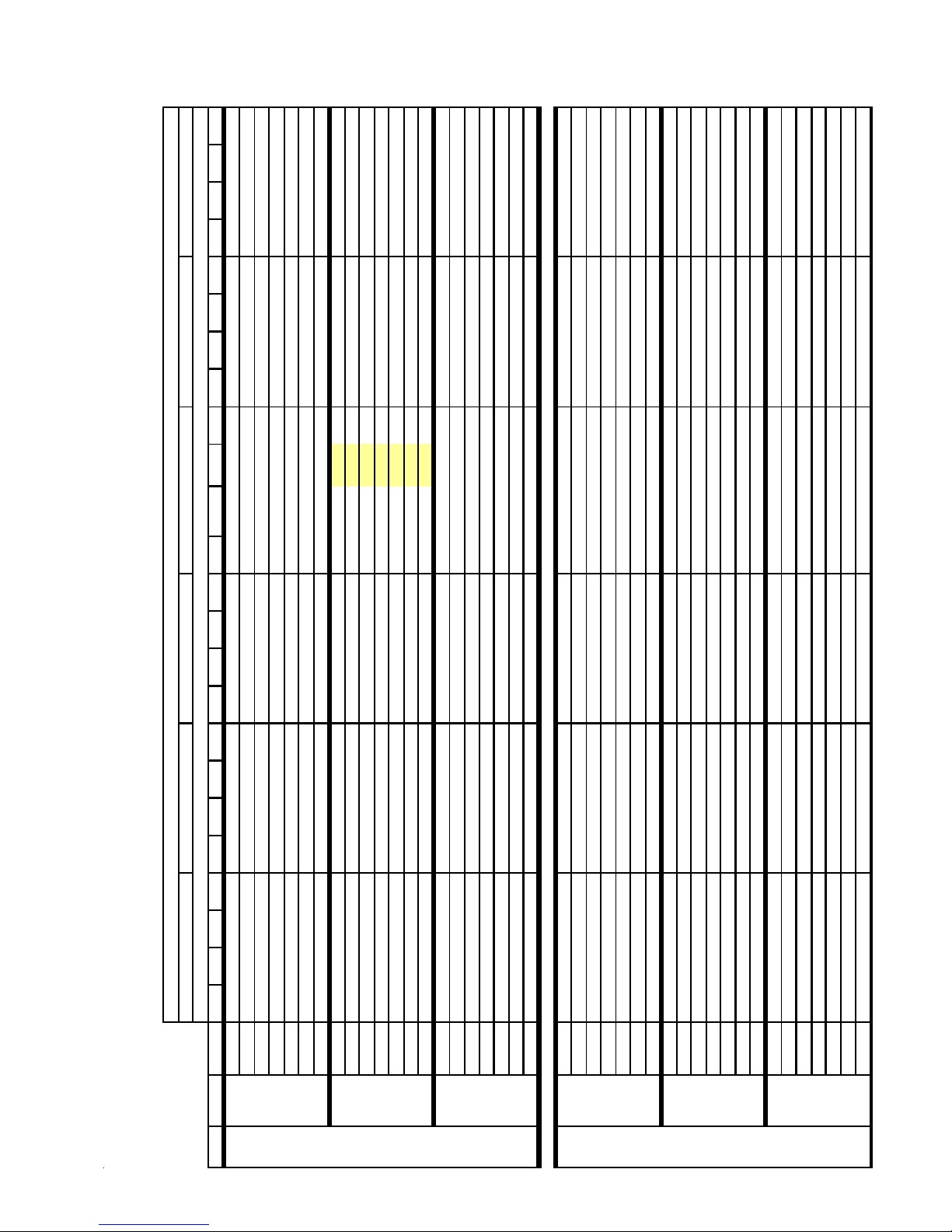
COOLING PERFORMANCE DA T A
5
5
5
5
*
w
9
3
7
9
3
9
3
7
9
3
9
5
5
5
5
9
A
S
5
8
5
5
R
5
R
8
5
8
5
9
5
8
8
5
5
R
5
R
8
5
5
8
9
9
8
8
A
S
5
9
9
5
8
R
9
9
R
9
9
5
5
8
9
5
8
A
S
8
8
5
8
8
R
R
9
8
9
8
5
5
9
9
8
8
A
S
5
9
9
5
8
R
9
9
R
9
5
5
9
8
9
8
A
S
5
8
9
5
8
9
R
5
R
8
5
67 71
11
6
*SZC180361A*-LOW ST AGE
C O OL ING OP ER ATIO N
71 5
6
6
24 21 17 23 22 20 16
17 24 24 21 16 22 22 19 15
27.0 22.0 22.5 24.0 25.7 20.4 20.8 22.3 23.8
67 71 5
6
24 21 17 2
71 5
6
Outdoor Ambient Temperature
85 95 10
6
Entering Indoor W et Bulb Tem perature
24 21 17 2
25 .3
6.7 6.9 7.2 7.0 7.1 7.4 7.7 7.4 7.6 7.8 8.1
6.7 6.
147 125 133 145 155 131 139 152 162 136 144 157 168
7.47.27.37.67.97.67.88.08.4
21
7.1
1.69 1.75 1.81 1.72 1.76 1.83 1.89 1.79 1.83 1.89 1.96
1.00 0.94 0.76 0.57 1.00 0.97 0.79 0.59 1.00 0.98 0.80 0.60
7.0 7.2 7.5 7.2 7.4 7.7 8.0 7.7 7.9 8.1 8.4
1.00 1.00 0.80 0.60 1.00 1.00 0.83 0.62 1.00 1.00 0.84 0.63
322 310 333 352 367 349 375 396 413 38 5 415 438 457
6.7 7.0 6.
0.77 0. 5
1.61 1.67 1.73 1.66 1.70 1.76 1.83 1.74 1.78 1.84 1.91 1.80 1.85 1.91 1.98
7.0 7.3 7.0 7.2 7.4 7.7 7.5 7.6 7.9 8. 2
6.6 6.
1.00 0.97 0.88 0.71 1.00 1.00 0.91 0.74 1.00 1.00 0.92 0.75
1.62 1.66 1.72 1.78 1.69 1.73 1.79 1.86 1.76 1.80 1.86 1.93
6.
0 . 94 0.85 0.6
24 21 22 23 23 20
26 25 21 24 2
7.0 7.2 7.5 7.2 7.4 7.7 8.0 7.7 7.9 8.1 8.4
322 310 333 352 367 349 375 396 413 38 5 415 438 457
140 149 126 134 147 156 132 141 154 164 137 146 159 169
6.7 7.0 6.
0.88 0.72 1. 00 1.00 0.91 0.74 1.00 1.00 0.95 0.77 1.00 1.00 0.95 0.77
1.61 1.67 1.73 1.66 1.70 1.76 1.83 1.74 1.78 1.84 1.91 1.80 1.85 1.91 1.98
7.0 7.3 7.5 7.3 7.5 7.7 8.0 7.7 7.9 8.2 8.5
1.72 1.78 1.84 1.75 1.80 1.86 1.93 1.82 1.86 1.93 2.00
1.00 1.00 0.96 0.78 1.00 1.00 0.99 0.80 1.00 1.00 1.00 0.81
7.0 6.
155 131 140 153 163 138 147 160 170 14 3 152 166 176
1.63 1.68 1.74 1.6
6.4 6.6 6.
0.52 0.93 0.87 0.71 0. 53 0.96 0.90 0.73 0.55 1.00 0.94 0.76 0.57 1.01 0.94 0.77 0.57
6.0 6.2 6.1 6.3 6.
7
EXPANDED PERFORMANCE DA TA
5.7 5.6 5.
1.44 1.43 1.46 1.51 1.56 1.52 1.56 1.61 1.67 1.61 1.64 1.70 1.76 1.68 1.72 1.78 1.84 1.74 1.78 1.84 1.91
6
59 63 67 71 59 63 67 71 5
irflo
MODEL: *SZC180361A* / CA*F3743*6** + TXV / MBVC1600**-1** Design Subcooling 5 - 7 °F @ the liquid service valve, AHRI 95° F test conditions
IDB
1.3
220233243230247261272261281297310298 320 338 353335360380397370398420438
5.2 5.3 5.
20
DT 25 24 21 17 25 24 21 17 2
MP
S/T 0.88 0.82 0.67 0.50 0.91 0.85 0.6
MBh 23.0 23.5 25.1 26.8 22.5 22.9 24.5 26.2 21.9 22.4 23.9 25.6 21.4 21.8 23.3 25.0 20.3 20.8 22.2 23.7 18.8 19.2 20.5 22.0
HI P
744 KW 1.32 1.3
122 1 33 142 119 127 13
11512613411
10
LO P
MBh 24.925.427.229.124.324.926.628.423.724.325.927.723.2 23.7
1.60 1.56 1.60 1.65 1. 71 1.6
1.46 1.50 1.5
0.52 0.94 0.88 0.72 0.54 0.97 0.91 0.74 0.5
0.6
1.43 1.4
DT 25 23 20 16 25 24 21 17 25 24 21 17 25 24
S/T 0.91 0.8
AMPS 5.4 5.5 5.7 5. 9 5.8 5.9 6.1 6.4 6. 3 6.5 6.7 6.9 6.7 6.9
80 850 KW 1.35 1.3
269 281 269 290 306 319 307 330 349 364345371392409381410433452
211 2 27 240 250 237 25
HI P
126 137 146 123 131 143 152 129 137 150 159135144157167140149162173
112 119 130 138 11
LO P
0.56 1.00 0.9
6.0 6.2 6.2 6.3 6.
6.0 6.2 6.4 6.4 6.
257 272 284 272 293 30
127 138 147 124 132 144 153 130 138 151 161 136 145 158 169 141 150 164 175
1.51 1.56 1.62 1.5
5.
1.4
5.7 5.
1.44 1.4
5.4 5.
213 229 242 253 23
113 120 131 140 11
DT 24 23 20 16 24 23 20 16 24 23 20 16 23 23 20 16 22 22 20 16 20 21 18 15
MP
S/T 0.95 0.90 0.73 0.54 1.00 0.93 0.7
MBh 25.7 26.2 28.0 29.9 25.1 25.6 27.4 29.2 24.5 25.0 26.7 28.5 23.9 24.4 26.0 27.8 22.7 23.2 24.7 26.5 21.0 21.5 22.9 24.5
HI P
LO P
956 KW 1.36 1.3
0.92 0.83 0.67 0.9
5.7 5.
0.9
1.44 1.47 1.52 1.57 1.53 1.57 1.62 1. 6
0.80 0.6
11612713511612313414312012
5.3 5.4 5.6 5.
207 223 235 245 232 250 264 275 264 284 300 313 301 323 342 356 338 364 384 401 374 402 425 443
10
DT 27 26 25 21 27 26 25 22 27 27 25 22 27 27 25 22 26 26 25 22 24 24 23 20
S/T 0.92 0.8
MBh 23.4 23.8 25.0 26.6 22.8 23.3 24.4 26.0 22.3 22.7 23.8 25.4 21.8 22.2 23.2 24.8 20.7 21.1 22.1 23.5 19.1 19.5 20.4 21.8
MP
744 KW 1.33 1.36 1.40 1 .4
MBh 25.3 25.8 27.1 28.9 24.7 25.2 26.4 28.2 24.2 24.6 25.8 27.5 23.6 24.0 25.2 26.8 22.4 22.8 23.9 25.5 20.7 21.1 22.1 23.6
HI P
LO P
6.0 6.2 6.4 6.4 6.
257 272 284 272 293 30
0.95 0.86 0.70 1.00 0.9
DT 26 26 24 21 26 26 25 21 26 26 25 21 2
S/T 0.95 0.92 0.83 0.67 0.9
127 138 147 124 132 144 153 130 138 151 161 136 145 158 169 141 150 164 175
1.51 1.56 1.62 1.5
5.
1.4
5.7 5.
1.44 1.4
5.4 5.
213 229 242 253 23
113 120 131 140 11
MP
HI P
LO P
85 850 KW 1.36 1.3
1.63 1.5
14014912513314
6.0 6.2 6.
1.52 1.5
6.0 5.
1.50 1.4
5.6 5.
232245255242260275286275296312326313 337 356 371352379400417389419442461
5.
21
114 121 132 141 120 12
DT25.09252320252524202424242023 24 24212223232021212219
S/T 1.00 0.97 0.87 0.71 1.00 1.00 0.90 0 .73 1.00 1.00 0.93 0.7
MBh 26.1 26.6 27.9 29.7 25.5 26.0 27.2 29.0 24.9 25.4 26.6 28.3 24.3 24.7 25.9 27.7 23.1 23.5 24.6 26.3 21.4 21.8 22.8 24.3
MP
HI P
LO P
956 KW 1.38 1.41 1.4
Shaded area is AHR I Rating Conditions ID B: Ent ering In door Dry Bulb Temperature KW=Total system power AMPS= outdoor unit amps (comp.+fan)
High and lo w pr es s ure s are mea s ured at the li quid and suc t ion serv ice val v es .
9
COOLING PERFORMANCE DA T A
5
5
5
5
g
e
*
w
9
3
7
9
3
9
3
7
9
3
0
0
6
-
-
9
7
9
-
7
3
6
-
0
9
9
7
9
-
-
A
S
-
-
R
6
6
-
-
R
9
5
-
-
5
7
9
-
-
9
6
9
-
6
5
-
0
0
9
3
8
5
-
-
R
0
-
-
R
6
3
9
-
-
6
8
0
7
3
-
-
8
6
8
-
6
5
-
0
5
6
0
7
-
-
A
S
-
-
R
5
6
3
-
-
R
7
5
0
-
-
9
3
6
5
7
7
3
0
7
9
0
0
8
5
9
9
A
S
R
8
8
R
3
6
5
6
5
7
7
8
8
0
5
0
5
6
3
0
5
0
5
7
A
S
R
5
6
3
R
7
5
0
6
8
7
9
9
0
9
9
6
8
0
7
8
5
3
6
7
9
A
S
R
7
9
6
R
8
6
g
67 71
12
11
6
12
11
*SZC180481A*-LOW ST AGE
16 11
15 10
C OOLI NG OP ERATION
18 1
0.1 0.1 0.1
36 2 390 412
0.80 0.67 0. 46
71 5
6
1
6
19 1
0.79 0.66 0.46
67 7 1 5
6
17 13
0.64 0.44
71 5
6
Indoor W et Bu lb Temperatur
Outdoor Ambient Temperature
85 95 10
Enterin
13 - 1
6
1
13 2 140 153
2.37 2.43 2. 51
0.1 0.1 0.1
328 353 372
128 136 148
2.28 2.34 2.42
2.24 2.32
- 122 129 141
2.12 2.19 - 2. 1
18 1
0.83 0.69 0. 48
0.82 0.69 0.47
0.66 0.46
0.64 0.44 - 0. 7
37 3 402 424
2.44 2.49 2. 58
12
19 1
338 364 384
2.35 2.40 2.49
17 13
2.30 2.38
- 300 323 341
13 - 1
2.25 - 2.2
1
2.1
17 1
13 6 145 158
131 140 153
- 125 133 146
0.1 0.1 0.1
37 7 406 429
0.87 0.72 0. 50
12
18 1
0.86 0.72 0.50
16 12
0.69 0.48
12 - 1
0.46 - 0.8
1
0.6
13 7 146 160
2.46 2.52 2. 61
12 21 1
1
0.1 0.1 0.1
341 367 388
133 141 154
2.37 2.43 2.51
17 12 22 20 16 11 20 19 15 11
143 152 129 137 150 159 133 142 155 165
35.9 38.5 30.6 31.5 34.1 36.6 28.3 29.2 31.6 33.9
2.32 2.40
- 303 326 345
- 127 135 147
2.27 - 2.2
21 17 12 22 2
0.78 0.59 0.38 0.90 0.80 0.61 0.39 0.91 0.81 0.61 0.40
0.8
2.21 2.26 2.34 2.42 2.31 2.36 2.44 2.53 2.39 2.45 2.54 2.63
0.57 0.3
2.14 2.21 2.2
33 .1
145 123
0.1 0.1 0.1 0.1 0.1 0.1 0.1 0.1 0.1 0.1
20
0.1
0.80 0.61 0.39 0.93 0.83 0.63 0.41 0.94 0.84 0.64 0.41
2.32 2.40 2.49 2.37 2.43 2.51 2.60 2.46 2.52 2.61 2.70
0.9
2.2
316 303 327 345 360 341 367 388 405 377 406 429 447
149 127 135 147 157 133 141 154 164 137 146 160 170
0.59 0.3
2.27 2.3
0.7
2.2
11 20 1
1
2.34 2.42 2.51 2.39 2.45 2.53 2.63 2.48 2.54 2.63 2.73
0.94 0.84 0.64 0.41 0.98 0.87 0.66 0.43 0.99 0.88 0.67 0.43
2.2
319 306 330 348 363 345 371 392 409 381 410 433 452
16 11 21 20 16 11 21 1
2.22 2.29 2.3
0.84 0.7
- 256 275 291 - 2 91 314 33 1
-11612313
7
EXPA NDED PERFORMANCE DA TA
- 0.72 0.60 0.42 - 0.74 0.62 0.43 - 0.7
- 1.94 1.98 2 .05 - 2.0
6
0.58 0.4
59 63 67 71 59 63 67 71 5
S/T 0.7
M Bh 31.4 3 2 .5 35.7 - 30.7 31.8 34.8 - 29.9 31.0 34.0 - 29.2 30.3 33.2 - 27.7 28.8 31.5 - 25.7 26.6 29.2 -
Ai rflo
MODEL: *SZC180481A* / CA*F4961*6** + TXV / MBVC2000**-1** Design Subcooling 5 - 7°F @ the liquid service valve, AHRI 95 test conditions
IDB
228 - 225 242 25
1.83 1.8
0.1 0.1 0.1 - 0.1 0.1 0.1 - 0 .1 0.1 0.1 - 0.1 0.1 0.1
200 21
DT 19 17 13 - 19 17 13 - 1
MP
KW 1.7
HI P
10 5
0 .62 0.43 - 0.7
106 112 123 - 111 119 12
DT 19 16 12 - 19 16 12 - 1
S/T 0.72 0.60 0.42 - 0.7
M Bh 34.0 3 5 .3 38.6 - 33.2 34.4 37.7 - 32.4 33.6 36.8 - 31.6 32.8 35.9 - 30.1 31.2 34.1 - 27.8 28.9 31.6 -
LO P
-11912713
2 .04 2.11 - 2.1
207 222 235 - 232 250 264 - 264 284 30
KW 1.84 1.88 1.94 - 1.9
HI P
AMPS 0. 1 0.1 0.1 - 0. 1 0.1 0.1 - 0.1 0.1 0.1 - 0.1 0.1 0.1 - 0.1 0.1 0.1 - 0.1 0.1 0.1 -
12 0
7
0 .65 0.45 - 0.8
126 - 115 122 13
0.63 0.44 - 0.7
109 11
DT 18 16 12 - 18 16 12 - 1
S/T 0.7
M Bh 35.0 3 6 .3 39.8 - 34.2 35.5 38.9 - 33.4 34.6 37.9 - 32.6 33.8 37.0 - 31.0 32.1 35.2 - 28.7 29.7 32.6 -
LO P
-26628730
-12112814
2 .00 2.07 2.14 2.0
1.9
- 2.01 2.05 2 .13 - 2.14 2.2
237 - 234 252 26
128 - 116 123 13
1.89 1.9
0.1 0.1 0.1 - 0.1 0.1 0.1 - 0 .1 0.1 0.1 - 0.1 0.1 0.1
209 22
110 11
MP
KW 1.8
HI P
LO P
13 5
0.34 0.82 0.73 0.55 0.3
0.71 0.5
1.85 1.91 1.9
0.10.10.10.10.10.10.10.10.10.10.10.10.1 0.1 0.1 0.1 0.1 0.1 0.1 0.1 0.1 0.1 0.1 0.1
DT 22 20 17 12 22 21 17 12 22 21 17 12 2
MP
S/T 0.7
KW 1.8
MBh 31.932.935.638.231.232.134.837.330.431.333.936.429.7 30.6 33.1 35.5 28.2 29.0 31.4 33.7 26.1 26.9 29.1 31.3
10 5
269 258 278 294 306 294 317 334 349 331 356 376 392 366 394 416 434
230 240 227 245 25
203 21
HI P
0.8
2.1
278 266 287 30
0 .76 0.57 0.3
0.8
2.01 2.05 2.13 2.2
0.3
2.0
124 132 113 120 131 139 117 125 13
107 11
S/T 0.82 0.73 0.5
MBh 34.635.638.541.433.834.837.740.433.034.036.839.432.2
LO P
237 247 234 252 26
1.89 1.9
0.10.10.10.10.10.10.10.10.10.10.10.10.1
209 22
DT 22 20 16 11 22 20 17 11 22 20 17 11 22
MP
KW 1.8
HI P
12 0
7
0.91 0.82 0.62 0.4
144 121 128 14
0 .80 0.60 0.3
0.8
0.3
128 136 116 124 13
0.77 0.5
110 11
S/T 0.8
MBh 35.636.739.742.634.835.838.841.634.035.037.940.633.1 34.1 36.9 39.6 31.5 32.4 35.1 37.7 29.2 30.0 32.5 34.9
LO P
280 269 290 30
145 122 130 142 151 128 136 149 158 134 143 156 166 139 148 161 172
2 .07 2.14 2.22 2.1
2.0
2.0
240 250 237 255 26
129 137 117 125 13
1.91 1.9
0.10.10.10.10.10.10.10.10.10.10.10.10.1 0.1 0.1 0.1 0.1 0.1 0.1 0.1 0.1 0.1 0.1 0.1
211 22
111 11
DT 21 19 16 11 21 19 16 11 21 1
MP
KW 1.8
HI P
LO P
13 5
h and low pressures are measured at the liquid and suction service valves.
Shaded area is ACCA (TVA) conditions IDB: Entering Indoor Dry Bulb Temperature KW=Total system power AMPS=outdoor unit amps (comp.+f an)
Hi
10
COOLING PERFORMANCE DA T A
A
5
5
5
5
g
*
9
3
7
9
3
9
3
7
9
3
7
6
9
9
6
3
5
5
7
5
7
5
7
3
3
9
9
6
3
A
S
R
7
R
5
7
9
7
6
9
5
6
5
6
3
6
7
8
5
7
5
6
8
9
R
7
7
6
R
8
7
5
5
7
3
6
3
3
6
6
8
9
6
9
6
8
A
S
R
9
9
3
9
R
9
8
7
3
9
7
3
8
7
6
7
6
6
6
5
3
8
3
5
A
S
R
5
R
6
5
9
7
5
7
8
9
6
9
6
8
R
9
9
3
9
R
9
8
7
3
9
6
9
9
3
3
3
8
8
6
3
A
S
R
6
R
8
67 71
11
6
22 19 15
*SZC180481A*-LOW ST AGE
COOLING OPERATION
2
71 5
6
6
67 71 5
6
71 5
6
Ind oo r W e t B ulb T emp e ra t ur e
Outdoor Ambien t Temperature
85 95 10
6
Enterin
24 21 1
2
24 21 1
0.89 0.73 0.54 0.99 0.93 0.75 0.56 0.99 0.93 0.76 0.57
2.28 2.36 2.44 2.33 2.38 2.47 2.56 2.41 2.47 2.56 2.65
2
0.9
309 297 320 338 352 334 360 380 396 370 398 420 438
0.70 0. 5
2.23 2.31 2. 2
24 21 1
22 22 19 15
20 1
24 2
1
38.2 31.1 31.8 34.0 36.3 28.8 29.4 31.5 33.6
35.8
146 124 132 144 154 130 138 151 161 135 143 156 167
0.1 0.1 0.1 0.1 0.1 0.1 0.1 0.1 0.1
21
0.1
24
0.92 0.75 0.56 1.00 0.96 0.78 0.58 1.00 0.97 0.79 0.59
2.34 2.42 2.51 2.39 2.45 2.54 2.63 2.48 2.54 2.63 2.73
2
2.2
319 307 330 348 363345371392409381410433452
24 20 1
0.90 0.73 0.54 0.9
2.22 2.29 2.3
20 21 18 15
21 24 24 23 20
2
2
22 22 20 1
20 1
2
2
1.00 0.97 0.79 0.59 1.00 1.00 0.82 0.61 1.00 1.00 0.83 0.62
322 310 333 352 367 348 375 396 413 385 414 437 456
152 129 138 150 160 136 144 157 168 140 149 163 173
20 1
2.24 2.31 2.40 2.31 2.36 2.45 2.53 2.41 2.47 2.56 2.65 2.50 2.56 2.65 2.75
25 22 2
2
2.30 2.38 2.47 2.35 2.40 2.49 2.58 2.44 2.49 2.58 2.68
1.00 0.96 0.87 0.70 1.00 1.00 0.90 0.73 1.00 1.00 0.91 0.74
2.2
148 125 133 146 155 131 140 153 163 136 145 158 168
25 21 2
0.84 0. 6
2.25 2. 3
2
0.9
2.1
0.87 0.71 1. 00 1.00 0.90 0.73 1.00 1.00 0.93 0.76 1.00 1.00 0.94 0.76
322 310 333 352 367 348 375 396 413 385 414 437 456
2.24 2.31 2.40 2.31 2.36 2.45 2.53 2.41 2.47 2.56 2.65 2.50 2.56 2.65 2.75
20 21 21 22 19
2
24 24 20 22 2
2.38 2.47 2.56 2.43 2.49 2.58 2.67 2.53 2.59 2.68 2.78
152 129 138 150 160 136 144 157 168 140 149 163 173
2.33 2.42 2. 3
0.51 0.92 0.8
2.16 2.11 2.1
7
EXPANDED PERFORMANCE DAT
MODEL: *SZC180481A* / CA*F4961*6** + TXV / MBVC2000**-1** Design Subcooling 5 - 7°F @ the liquid service valve, AHRI 95 test conditions
0.90 0.84 0.6
1.97 2.02 2.0
0.4
1.9
6
0.81 0.6
0.1 0.1 0.1 0. 1 0.1 0.1 0. 1 0.1 0.1 0. 1 0.1 0.1 0.1 0.1 0.1 0.1 0.1 0.1 0.1 0.1 0.1 0.1 0.1 0.1
20522023224223024726127226128129
DT 25 24 21 16 25 24 21 17 2
MP
S/T 0.8
MBh 32.5 33.2 35.5 37.9 31.7 32.4 34.6 37.0 31.0 31.7 33.8 36.2 30.2 30.9 33.0 35.3 28.7 29.3 31.3 33.5 26.6 27.2 29.0 31.0
Airflow 59636771596367715
IDB
HI P
10 50 KW 1.82 1 .86 1.9
12513311412113214111812613
108 11
LO P
MBh 35.236.038.441.134.435.137.540.133.634.336.639.232.7 33.5
122 130 142 151 128 136 149 158134143156166139148161172
2.22 2.1
0 . 71 0.53 0.9
2.1
255 269 280 269 290 30
2.03 2.0
0 . 51 0.93 0.8
2.0
240 250 23
1.91 1.9
211 22
DT 24 23 20 16 25 24 20 16 2
S/ T 0.90 0 .84 0.6
HI P
AM PS 0.1 0.1 0.1 0. 1 0.1 0.1 0. 1 0.1 0.1 0. 1 0.1 0.1 0.1 0.1
80 1200 KW 1.8
0.56 1.00 0.94 0.76 0. 5
125 136 14
129 137 11
111 11
S/ T 0.94 0 .88 0.72 0.54 1.00 0.92 0.7
MBh 36.3 37.1 39.6 42.3 35.4 36.2 38.7 41.3 34.6 35.3 37.7 40.3 33.7 34.5 36.8 39.4 32.0 32.7 35.0 37.4 29.7 30.3 32.4 34.6
LO P
272 292 30
123 131 14
2.24 2.1
2.1
257 272 28
126 138 14
2.04 2.0
2.0
242 252 23
130 139 11
1.93 1.9
0.1 0.1 0.1 0. 1 0.1 0.1 0. 1 0.1 0.1 0. 1 0.1 0.1 0.1 0.1 0.1 0.1 0.1 0.1 0.1 0.1 0.1 0.1 0.1 0.1
213 22
112 11
DT 23 22 19 15 24 23 20 16 24 2
MP
HI P
LO P
13 50 KW 1.8
0 . 64 0.94 0.91 0.82 0.67 0.9
S/ T 0.91 0 .88 0.7
MBh 33.1 33.7 35.3 37.7 32.3 32.9 34.5 36.8 31.5 32.1 33.7 35.9 30.8 31.4 32.8 35.0 29.2 29.8 31.2 33.3 27.1 27.6 28.9 30.8
264 284 300 312 300 323 341 356 338 364 384 400 373 402 424 442
0.69 1.00 0.9
122 133 142 119 127 13
0.98 0.94 0.8
126 135 11
0.1 0.1 0.1 0. 1 0.1 0.1 0. 1 0.1 0.1 0. 1 0.1 0.1 0.1 0.1 0.1 0.1 0.1 0.1 0.1 0.1 0.1 0.1 0.1 0.1
20722223524523224926327
109 11
DT 26 26 24 21 27 26 25 21 2
MP
10 50 KW 1.84 1 .88 1.94 2.01 1.99 2.04 2.11 2. 18 2 .1
S/ T 0.94 0 .91 0.82 0.6
MBh 35.8 36.5 38.2 40.8 35.0 35.7 37.4 39.8 34.2 34.8 36.5 38.9 33.3 34.0 35.6 38.0 31.7 32.3 33.8 36.1 29.3 29.9 31.3 33.4
HI P
LO P
272 292 30
123 131 14
2.24 2.1
2.1
257 272 28
2.04 2.0
2.0
242 252 23
1.93 1.9
213 22
DT 26 25 24 21 26 26 24 21 26 26 24 21 26 26 25 21 24 25 24 21 22 23 23 20
HI P
AM PS 0.1 0.1 0.1 0. 1 0.1 0.1 0. 1 0.1 0.1 0. 1 0.1 0.1 0.1 0.1 0.1 0.1 0.1 0.1 0.1 0.1 0.1 0.1 0.1 0.1
85 1200 KW 1.8
0.72 1.00 1.00 0.91 0. 74 1.00 1.00 0.94 0.77 1.00 1.00 0.98 0.79 1.00 1.00 0.99 0.80
0.8
126 138 14
0 . 70 1.00 0.9
130 139 11
0.95 0.8
112 11
S/T 0.9
MBh 36.9 37.6 39.4 42.0 36.0 36.7 38.5 41.0 35.2 35.9 37.6 40.1 34.3 35.0 36.6 39.1 32.6 33.2 34.8 37.1 30.2 30.8 32.2 34.4
LO P
2.26 2.20 2.2
2.06 2.11 2.1
DT24.8224232025252320242423202
1350 KW 1.90 1.94 2.01 2.0
0.1 0.1 0.1 0. 1 0.1 0.1 0. 1 0.1 0.1 0. 1 0.1 0.1 0.1 0.1 0.1 0.1 0.1 0.1 0.1 0.1 0.1 0.1 0.1 0.1
MP
275 295 312 325 313 336 355 371 352 379 400 417 389 418 442 461
21523124425524126027428
HI P
124 132 144 154 131 139 152 162 137 146 159 169 142 151 164 175
11312013214012012713914
LO P
Shaded area is AHRI Rating Conditions IDB: Entering Indoor Dry Bulb Temperature KW=Total system power AMPS=outdoor unit amps (comp.+fan)
High and low pressures are measured at the liquid and suction service valves.
11
COOLING PERFORMANCE DA T A
5
5
5
5
g
e
*
w
9
3
7
9
3
9
3
7
9
3
5
5
8
8
7
0
8
-
-
9
9
-
9
0
7
-
0
7
0
6
3
0
8
-
-
A
8
0
3
5
8
7
-
-
R
8
6
-
-
7
9
-
-
8
7
9
0
9
0
-
-
8
9
-
8
0
7
-
0
3
9
7
3
9
7
6
-
-
R
5
3
0
-
-
8
3
-
-
9
6
3
8
-
-
0
8
8
-
8
3
9
6
-
0
5
9
5
3
0
9
-
-
A
7
9
8
6
-
-
R
7
6
3
-
-
9
-
-
7
0
7
9
9
3
5
3
3
5
3
3
9
3
3
0
9
3
9
3
6
A
9
8
6
9
6
5
8
6
R
0
0
8
8
6
5
0
7
9
0
5
3
6
5
3
0
5
9
8
5
0
3
0
0
9
A
7
9
9
8
9
6
R
7
7
6
3
0
9
5
5
5
7
6
7
7
9
2
8
0
0
7
3
0
8
3
6
3
A
5
8
0
3
0
9
0
7
R
0
0
9
6
3
0
5
g
67 71
13
11
6
1
13
1
12
1
*SZC180601A*-LOW ST AGE
17 11
21 17 12
2
36 2 390 411
0.75 0.63 0.43
COOLING OPERATI ON
71 5
6
14
6
21 1
0.75 0.62 0.43
67 71 5
14
6
71 5
6
In door W et Bulb Temperatur
Outdoor Ambien t Temperature
85 95 10
Enterin
14 - 22 1
0.40 - 0. 72 0.60 0.42
6
0.5
12 6 134 146
3.02 3.10 3.21
12.6 12.9 13.4
328 353 372
122 130 142
2.91 2.98 3.09
11.9 12.2 12 . 6
2.85 2.95
-116124135
2.79 - 2. 7
11.0 - 11.1 11.4 11.8
2.7
2
0.78 0.65 0.45
0.77 0.65 0.45
0.42 - 0. 74 0.62 0.43
37 3 402 424
3.11 3.18 3.30
14
21 1
338 364 384
2.99 3.07 3.18
14
2.93 3.04
-300323341
14 - 21 1
2.87 - 2. 8
13 0 138 151
126 134 146
-120128139
1
0.82 0.68 0.47
1
20 1
0.81 0.68 0.47
14
0.65 0.45
13 - 21 1
0.44 - 0. 7
1
0.6
37 7 406 428
13 1 140 152
3.14 3.21 3.33
13.1 13.4 13.9
341 367 388
127 135 147
3.02 3.09 3.21
12.3 12.7 13 . 1
2.96 3.06
11.9 12.3
-303326345
2.90 - 2. 8
2.8
11.1 11.5 - 11.
2
1
1
1 9 13 25 2
2
2
11.2 11.5 11.9 12.4 12.0 12.3 12.7 13.2 12.7 13.1 13.5 14.0
19 1
11.1 11.
2
0.71 0.54 0.34 0.82 0.73 0.55 0.36 0.85 0.76 0.57 0.37 0.85 0.76 0.58 0.37
2.72 2.82 2.92 2.81 2.88 2.98 3.09 2.94 3.01 3.12 3.23 3.05 3.12 3.24 3.36
10.
19 13 24 22 18 13 23 21 17 12
136 145 123 131 143 152 127 135 148 158
42.6 45.7 36.3 37.4 40.4 43.4 33.6 34.6 37.5 40.2
39.3
138 117
12.3 12.8 12.3 12.7 13.1 13.6 13.1 13.4 13.9 14.5
2
0.76 0.57 0.37 0.88 0.79 0.59 0.38 0.89 0.79 0.60 0.39
2.96 3.06 3.18 3.02 3.09 3.21 3.32 3.14 3.21 3.33 3.45
11.9
0.8
2.8
11.
316 303 326 345 360 341 367 388 404 377 406 428 447
0.55 0. 3
2.90 3. 0
2.8
11.1 11.5 11.
12 22 2
1 8 12 23 22 1
0.79 0.60 0.39 0.92 0.82 0.62 0.40 0.93 0.83 0.63 0.40
12.0 12.4 12.9 12.5 12.8 13.2 13.7 13.2 13.6 14.0 14.6
0.8
2.91 2.98 3.09 3.20 3.05 3.12 3.24 3.35 3.17 3.24 3.36 3.48
11.
319 306 330 348 363 345 371 392 409 381 410 433 451
144 122 130 142 151 128 136 149 159 133 141 154 164
0.58 0. 3
0.7
2 . 82 2.92 3.0
11.2 11.6 12.
-256275291-291313331
0.39 - 0.7
0.5
-0.6
0.3
0.5
DT 21 18 14 - 22 19 14 - 22 1
S/T 0.6
10.1 - 10.4 10.
9.
2 . 52 2.61 - 2 .6
-2.4
-9.
9.
9.
2.32 2.4
MPS 8.
KW 2.2
10 5
-22524225
200 216 22
HI P
7
EXPANDED PERFORMANCE DA TA
6
59 63 67 71 59 63 67 71 5
MBh 37. 3 38.6 42.3 - 36.4 37.7 41.3 - 35.5 36.8 40.4 - 34.7 35.9 39.4 - 32.9 34.1 37.4 - 30.5 31.6 34.6 -
Ai rfl o
MODEL: *SZC180601A* / CA*F4961*6** + TXV / MBVC2000**-1** Design Subcooling 5 - 7 °F @ the liquid service valve, AHRI 95 test conditions
12
IDB
-107113124-11111812
MBh 40. 4 41.8 45.9 - 39.4 40.9 44.8 - 38.5 39.9 43.7 - 37.6 38.9 42.7 - 35.7 37.0 40.5 - 33.1 34.3 37.5 -
LO PR 101 107 11
0.41 - 0.72 0.6
0.5
-0.7
0.3
0.5
DT 21 18 14 - 21 18 14 - 21 1
S/T 0.6
2.68 - 2.71 2.7
2.5
-2.5
2.4
2.3
KW 2.3
AM PS 9. 1 9. 3 9.6 - 9.8 10.1 10.4 - 10.7 11.0 11.4 - 11.5 11.8 12.2 - 12.2 12.5 13.0 - 13.0 13.3 13.8 -
70 120
-26428430
-11412113
-23224926
207 222 23
HI P
LO PR 104 111 121 - 110 117 12
2
2.6
10.
-26628730
-115123134-121129141
0.52 0.34 0.7
10.2 10.
2 . 61 2.71 - 2 .7
10.2 10.5 - 10.
-2.5
-9.
-23425226
0.41 - 0.74 0.62 0 .43 - 0.7
2.41 2.4
209 225 23
DT 20 17 13 - 20 18 13 - 2
S/T 0.71 0.5
MPS 9. 1 9. 4 9.
KW 2.3
MBh 41. 6 43.1 47.2 - 40.6 42.1 46.1 - 39.7 41.1 45.0 - 38.7 40.1 43.9 - 36.8 38.1 41.7 - 34.0 35.3 38.7 -
HI P
13 5
MBh 37.9 39.0 42. 2 45.3 37.0 38.1 41.3 44.3 36.1 37.2 40.3 43.2 35.3 36.3 39.3 42.2 33.5 34.5 37.3 40.1 31.0 31.9 34.6 37.1
LO PR 105 112 122 - 111 118 12
9.
0.6
2 . 54 2.63 2.7
9.
0.32 0.7
2.51 2.4
0.5
9.1 9.4 9.
2.34 2.4
DT 25 23 19 13 25 23 19 1
S/T 0.74 0.6
MPS 8.
KW 2.2
10 5
0.82 0.7
2.7
10.
269258278294306294 317 334 349 331 356 376 392 366 394 416 434
13311211913
0 . 72 0.54 0.3
227 244 25
108 114 12
24
12
0.52 0.34 0.8
0.6
202 218 23
S/T 0.7
MBh 41.1 42.3 45. 8 49.1 40.1 41.3 44.7 48.0 39.2 40.3 43.6 46.8 38.2
HI P
LO PR 102 108 11
27826628730
2 . 61 2.71 2.8
10.2 10.5 10.
234 252 26
2.5
24
2.5
10.1 9.
2.41 2.4
209 225 23
DT 24 22 18 13 25 23 19 13 25 23 19 13 25
MPS 9. 1 9. 4 9.
KW 2.3
HI P
75 120
0.8
2.7
10.
137115123134143121 129 141 150 127 135 147 157 131 140 152 162
0.57 0.3
111 118 12
0.84 0.7
0.3
S/T 0.810.720.5
MBh 42.3 43.5 47. 1 50.6 41.3 42.5 46.0 49.4 40.3 41.5 44.9 48.2 39.3 40.5 43.8 47.1 37.4 38.5 41.7 44.7 34.6 35.6 38.6 41.4
LO PR 105 112 122 13
28026928930
13911612413
10.6 11.
2 . 64 2.73 2.8
10.
237 255 26
2.5
25
131 112 119 13
10.2 10.
9.
2.51 2.6
2.4
211 227 24
DT 23 21 18 12 24 22 18 12 24 22 18 12 24 2
MPS 9. 2 9.
KW 2.3
HI P
LO PR 106 113 12
13 5
h and low pressures are measured at the liquid and suction service valves.
Shaded area is ACC A (TVA ) conditions IDB: Entering Indoo r Dry B ulb Temperature KW=Total syste m p ow er A MPS= outdoor unit amps (co mp .+f an)
Hi
 Loading...