

Goodman RS6100004, RS6200006, ARUF 14 series, ARPT 14 series, ASPT 14 series Technical Manual
...Page 1
TECHNICAL MANUTECHNICAL MANU
TECHNICAL MANU
TECHNICAL MANUTECHNICAL MANU
ALAL
AL
ALAL
ACNF , ADPF , AEPF , ARPF , ARUF ,
ASPF, ATUF, A WUF Air Handlers
• Refer to Service Manual RS6100004 & RS6200006 for installation, operation & troubleshooting information.
• All safety information must be followed as provided in the Service Manual.
• Refer to the appropriate Parts Catalog for part number information.
• Models listed on page 3.
This manual is to be used by qualified, professionally trained HVAC technicians only. Goodman
does not assume any responsibility for property damage or personal injury due to improper
service procedures or services performed by an unqualified person.
Copyright © 2007-2013 Goodman Company, L.P.
RT6121000r20
September 2013
Page 2
PRODUCT IDENTIFICATION
)
The model number is used for positive identification of component parts used in manufacturing. Please use this number
when requesting service or parts information.
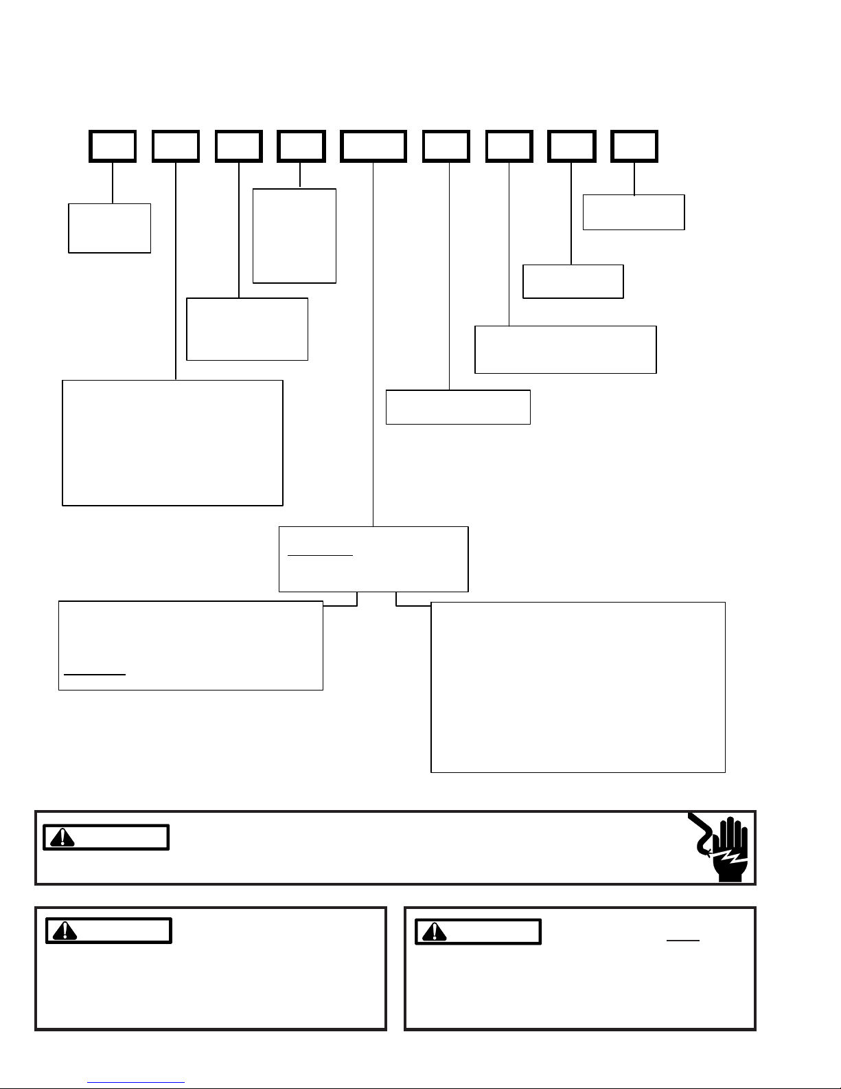
A W U F 3642 1 6 A A
EXPANS ION
PRODUCT
TYPE:
A: Air Handler
CA BINET FI NISH:
U: Unpainted
P: Painted
N : Uncased
APPLICATION
C: C eiling Mount PS C Motor
D: Do wn flo w P S C M otor
E: Multi-P osition Varible Speed Motor
S: Energy-Efficient Motor
R: Multi-Position PSC Motor
T: Coated Coils
W: Wall Mount PSC Motor
DEV ICE :
F: Flowrat er
T: TXV
(Expansion
Device)
MINOR
REVISION*
MAJOR
REVISION*
REFRIGERANT CHARGE:
No Digit: R-22 Only
6: R-410A or R-22
ELECTRICAL:
1: 208 - 230 V / 1ph/60Hz
NOM INAL CA PACITY RANGE:
@ 13 SEER
Dedicated Appl icat ion
36 36 : 3 Tons
Multi- P osition & Downflow Ap plication s
3137: 3 Tons
3642: 3 - 3 1/2 Tons
183 0 : 1 1/2 - 3 1/ 2 T o ns
@10 SEER
172 9 : 1 1/2 - 2 1/ 2 T o ns (for export systems
All Airhandlers use DIRECT DRIVE MOTORS. Power supply is AC 208-230v, 60 hz, 1 phase.
HIGH VOLTAGE!
WARNING
WARNING
WARNING
WARNING
arising from improper service or service procedures. If
you install or perform service on this unit, you assume
responsibility for any personal injury or property damage
which may result. Many jurisdictions require a license to
install or service heating and air conditioning equipment.
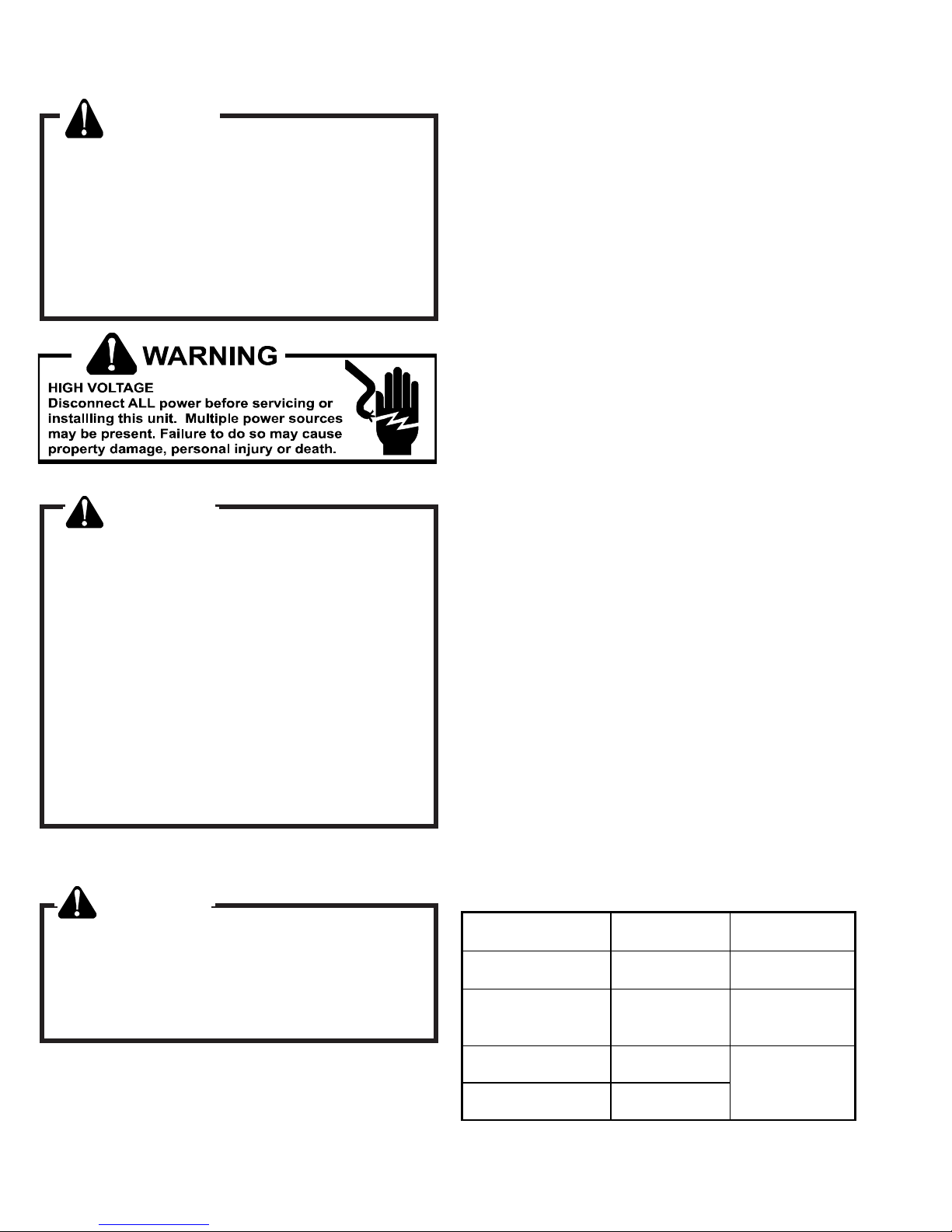
Disconnect ALL power before servicing or installing this unit. Multiple power
sources may be present. Failure to do so may cause property damage, personal
injury or death.
Goodman will not be responsible
for any injury or property damage
Ceiling M o unt & Wall Mount Applicatio ns
(Nomin al Cooling Capacity/E lectric Heat kW)
1803 : 1 1/2 To ns Co o li n g / 3 kW Elec tric He at
1805 : 1 1/2 To ns Co o li n g / 5 kW Elec tric He at
2405: 2 Tons Cooling / 5 kW Electric Heat
3608: 3 Tons Cooling / 8 kW Electric Heat
310 5: 1.5 - 2. 5 Tons Co oling / 5k W Ele c tric Hea t
3210: 2 - 2.5 Tons Cooling / 10kW Electric Heat
3705: 3 Tons Cooling / 5 kW Electric Heat
3708: 3 Tons Cooling / 8 kW Electric Heat
3710: 3 Tons Cooling / 10 kW Electric Heat
WARNING
WARNING
ments of an "entry level technician", at a minimum, as
specified by the Air-Conditioning, Heating, and Refrigeration Institute (AHRI). Attempting to install or repair this
unit without such background may result in product
damage, personal injury or death.
Installation and repair of this unit
should be performed
dividuals meeting the require-
ONLY by in-
2
Page 3

PRODUCT IDENTIFICATION
The model number is used for positive identification of component parts used in manufacturing. Please use this number
when requesting service or parts information.
ACNF18001**
ACNF18051**
ACNF18061**
ACNF18081**
ACNF24001**
ACNF24051**
ACNF24061**
ACNF24081**
ACNF24101**
ACNF30001**
ACNF30051**
ACNF30061**
ACNF30081**
ACNF30101**
ACNF180016D*
ACNF180516D*
ACNF180616D*
ACNF180816D*
ACNF240016D*
ACNF240516D*
ACNF240616D*
ACNF240816D*
ACNF241016D*
ACNF300016D*
ACNF300516D*
ACNF300616D*
ACNF300816D*
ACNF301016D*
ADPF18241**
ADPF30421**
ADPF48601**
ADPF182416
ADPF304216**
ADPF486016**
AEPF18301**
AEPF30361**
AEPF31371**
AEPF42601**
ARPF18241**
ARPF30301**
ARPF37431**
ARPF48601**
ARPF182416**
ARPF193116**
ARPF303016**
ARPF363616**
ARPF364216**
ARPF374316**
ARPF486016**
ARPF496116**
ARUF18241**
ARUF30301**
ARUF36421**
**
ARUF37431**
ARUF48601**
ARUF172916**
ARUF182416**
ARUF193116**
ARUF303016**
ARUF363616**
ARUF364216**
ARUF374316**
ARUF486016**
ARUF496116**
ASPF183016*
ASPF303616*
ASPF313716*
ASPF426016*
ATUF182416**
ATUF193116**
ATUF303016**
ATUF363616**
ATUF364216**
ATUF374316**
ATUF486016**
AWUF18051**
AWUF18081**
AWUF24051**
AWUF24081**
AWUF24101**
AWUF30051**
AWUF30081**
AWUF30101**
AWUF36051**
AWUF36081**
AWUF36101**
AWUF37051**
AWUF37081**
AWUF37101**
AWUF180316**
AWUF240316**
AWUF300316**
AWUF240316B*
AWUF240516B*
AWUF240816B*
AWUF241016B*
AWUF310516A*
AWUF310816A*
AWUF321016A*
WARNING
WARNING
WARNING
WARNING
Serious property damage, personal injury, reduced unit
performance and/or hazardous conditions may result
from the use of such non-approved devices.
The United States Environmental Protection Agency (“EPA”) has issued various regulations regarding the introduction and disposal of refrigerants introduced into this unit. Failure to follow
these regulations may harm the environment and can lead to the imposition of substantial fines.
These regulations may vary by jurisdiction. Should questions arise, contact your local EPA office.
Do not connect or use any device
that is not design certified by
Goodman for use with this unit.
WARNING
WARNING
do not store combustible materials or use gasoline or
other flammable liquids or vapors in the vicinity of this
appliance.
To prevent the risk of property
damage, personal injury, or death,
3
Page 4
PRODUCT DESIGN
WARNING
When installing or servicing this equipment, safety
clothing, including hand and eye protection, is
strongly advised. If installing this equipment in an
area that has special safety requirements (hard hats
etc.), observe these requirements. To protect the
unit when brazing close to the painted surfaces,
the use of a quenching cloth is strongly advised to
prevent scorching or marring of the equipment finish.
WARNING
The unit MUST have an uninterrupted, unbroken
electrical ground to minimize the possibility of personal injury if an electrical fault should occur. The
electrical ground circuit may consist of an appropriately sized electrical wire connecting the
ground lug in the unit control box to the building
electrical service panel. Other methods of grounding are permitted if performed in accordance with
the “National Electric Code” (NEC)/“American National Standards Institute” (ANSI)/“National Fire
Protection Association” (NFPA) 70 and local/state
codes. In Canada, electrical grounding is to be in
accordance with the Canadian Electric Code CSA
C22.1. Failure to observe this warning can result
in electrical shock that can cause personal injury
or death.
AIR HANDLERS
*See Air Handler Specification Sheet for Proper Combinations.
ALL AIR HANDLERS USE DIRECT DRIVE MOTORS. POWER SUPPLY IS 220-240 V, 60 HZ, 1
PHASE
Installation
Before installing this appliance insure that it is properly sized
and adequate power is available.
This appliance can be installed in the vertical or right horizon-
tal position without modification. The horizontal left and
downflow positions require product modification.
This product is designed for zero inches (0 inches) clearance; however, adequate access for service or replacement
must be considered without removing permanent structure.
This unit can be installed on a platform when deemed necessary.
In an attic installation a secondary drain pan must be provided by the installer and placed under the entire unit with a
separate drain line properly sloped and terminated in an area
visible to the owner. This secondary drain pan is required in
the event that there is a leak or main drain blockage. Closed
cell insulation should be applied to the drain lines in unconditioned spaces where sweating may occur.
Appliances installed in garages, warehouses or other areas
where they may be subjected to mechanical damage must
be suitably guarded against such damage by installing behind protective barriers, being elevated or located out of the
normal path of vehicles. When installed on a base, the base
must also be protected by similar means.
Heating and cooling equipment located in garages, which
may generate a glow, spark or flame capable of igniting flammable vapors, must be installed with the ignition source at
least 18"[46cm] above the floor level.
When more than one appliance is installed in a building it
shall be permanently identified as to the area or space serviced by the equipment.
When this product is installed in the downflow installation in
an unconditioned space, remove the horizontal drain pan and
install the following insulation kit
WARNING
If this appliance is installed in an enclosed area
such as a garage or utility room with any carbon
monoxide (CO) producing appliance (i.e. automobile, furnace, water-heaters, etc.), ensure the area
is properly ventilated.
4
ARUF, ATUF
or A RPF M odel
1729
1824
3030
1931
3636
3642 3036
3743
4860
4961
This kit is used to prevent sweating on the vertical drain pan.
AEPF / ASPF Insulation Kit
N/A
1830
3137
4260
DPI18-30/20
DPI36-42/20
DPI48-61/-20
Page 5

PRODUCT DESIGN
To prevent the horizontal drain pan from sweating in high
humidity applications, it is recommended that a DPIH
insulation accessory kit be used. NOTE: The DPIH insulation kit is not supplied with this product and must be
purchased separately.
See Chart below for the correct DPIH kit.
A RUF, ATUF
or ARPF Model
1729
1824
3030
1931
3636
3642 3036
3743 3137
4860
4961
ACNF AC electric heat air handlers are designed for ceiling
mounting and have a direct drive, multi-speed motor. They
are available in 1-1/2, 2 and 2 1/2 ton sizes.
AWUF is a vertical stud or wall-mount electric heat air handler and features a direct drive, multi-speed motor. The AWUF
has a check flowrater for cooling only and heat pump operation, with sequence controlled heating elements of 5, 8, and
10 kW. The AWUF is available in 1 1/2 to 3 ton sizes.
ADPF is a dedicated downflow, multi-speed air handler and
is available in 1 1/2 to 5 ton sizes. Electric heat kits are
available as a field-installed option.
AEPF / ASPF Ins ulation Kit
N/A
1830
4260
DPIH18-32
DPIH36-42
DPIH48-61
*ARPF air handlers are multi-position, multi-speed with direct drive motors. They are available in 1 1/2 to 5 ton sizes
with optional 3 kW to 21kW electric heat kits available for
field installation. (See note below.)
ARUF is a multi-position air handler and can be used with R410A or R-22 (models ending in 1/16) and features a direct
drive, multi-speed motor. The ARUF has a check flowrater for
cooling-only and heat pump operation. The ARUF is available in 1 1/2 to 5 ton sizes.
*AEPF is a multi-position, variable-speed air handler and can
be used with R-410A or R-22 (models ending in 1/16). The
unit's blower design includes a variable-speed DC motor and
is compatible with heat pumps and variable-capacity cooling
applications. (See note below.)
*ASPF is a multi-position air handler that can be used with R410A or R-22 and it features a energy efficient motor. This
motor is a constant torque motor with very low power
consumption and it is energized by a 24V signal. The energy
efficient motor features an integrated control module and is
compatible with heat pumps and cooling applications. (See
note below.)
*NOTE: Factory-sealed to achieve a 2% or less leakage rate
at 1.0" water gauge external duct static pressure.
Complies with the Factory-sealed Air Handling Credit as
listed in the 2001 Florida Building Code, Chapter 13, Section
610.2.A.2.1.
5
Page 6
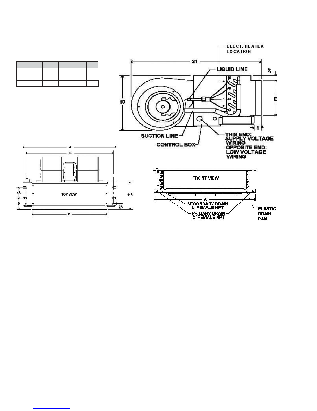
PRODUCT DIMENSIONS
D
IMENSIONS
ACNF
Model A B C D
ACNF18 37¼” 34
ACNF24 43¼” 40
ACNF30 49¼” 46
AC18 37¼” 34
AC30 43¼” 40
AC36 49¼” 46
11
/16” 30” 6½”
11
”
36” 6½”
/
16
11
/16” 42” 6½”
11
/16” 30” 6½”
11
”
36” 6½”
/
16
11
/16” 42” 6½”
6
Page 7
PRODUCT SPECIFICA TIONS
ACNF*****AA/AB (copper coils)
ACNF
ACNF18001
ACNF18051
ACNF18061
ACNF18081
ACNF24001
ACNF24051
ACNF24061
Blower
Diam eter 5.75 5.75 5.75 5.75 6.31 6.31 6.31 6.31 6.31 6.75 6.75 6.75 6.75 6.75
Width 6.75 6.75 6.75 6.75 8.25 8.25 8.25 8.25 8.25 8.25 8.25 8.25 8.25 8.25
Coil Dr a in Connection FPT 3/4" 3/4" 3/4" 3/4" 3/4" 3/4" 3/4" 3/4" 3/4" 3 /4" 3/4" 3/4" 3/4" 3/4"
Lineset Connection Size
Liquid 3/8" 3/8" 3/8" 3/8" 3/8" 3/8" 3/8" 3/8" 3/8" 3/8" 3/8" 3/8" 3/8" 3/8"
Suction 3/4" 3/4" 3/4" 3/4" 3/4" 3/4" 3/4" 3/4" 3/4" 3/4" 3/4" 3/4" 3/4 " 3/4"
Electrical Data
Min. Circuit Ampacity @ 240V 0.9 27 33.5 40.5 1.68 27.8 34.3 41.3 54.9 1.68 27.8 34.3 41.3 54.9
Min. Circuit Ampacity @ 208V 0.9 2405 30.5 36.8 1.68 25.3 31.36 37.6 49.8 1.68 25.3 31.3 37.6 49
Max. Overcurrent Device 240V 15 30 40 50 15 30 40 50 60 15 30 40 50 8
Max. Overcurrent Device @ 208V 15 30 40 40 15 30 40 40 50 15 30 40 40 60
Minimum VAC 197 197 197 197 197 197 197 197 197 197 197 197 197 50
Maximum VAC 253 253 253 253 253 253 253 253 253 253 253 253 253 253
Blower Motor
FLA 0.72 0.72 0.72 0.72 1.34 1.34 1.34 1.34 1.34 1.34 1.34 1.34 1.34 1.34
HP 1/81/81/81/81/41/41/41/41/41/41/41/41/41/4
Ship Weight (lbs)
59 59 59 59 69 69 69 69 69 79 79 79 79 79
ACNF24081
ANF24101
ACNF30001
ACNF30051
ACNF30061
ACNF30081
ACNF30101
ACNF*****DA (with aluminum coils)
ACNF180016
ACNF180516
ACNF180616
ACNF180816
ACNF240016
ACNF240516
ACNF240616
Blower
Diameter 5.75 5.75 5.75 5.75 6.31 6.31 6.31 6.31 6.31 6.75 6.75 6.75 6.75 6.75
Width 6.756.756.756.758.258.258.258.258.258.258.258.258.258.25
Coil Drain Connection FPT 3/4"3/4"3/4"3/4"3/4"3/4"3/4"3/4"3/4"3/4"3/4"3/4"3/4"3/4"
Lineset Connect ion Size
Liquid 3/8" 3/8" 3/8" 3/8" 3/8" 3/8" 3/8" 3/8" 3/8" 3/8" 3/8" 3/8" 3/8" 3/8"
Suction 3/4"3/4"3/4"3/4"3/4"3/4"3/4"3/4"3/4"3/4"3/4"3/4"3/4"3/4"
Electrical Data
Min. Circuit Am pacity @ 240V 0. 9 27 33.5 40.6 1.68 27. 8 34.3 41.3 54. 9 1.68 27.8 34. 3 41.3 54.9
Min. Circuit Am pacity @ 208V 0. 9 23.5 29.2 35.3 1.68 24. 3 36.1 47. 8 49.8 1.68 24. 3 29.9 36.1 47. 8
Max. Overcurrent Device 240V 15 30 35 45 15 30 45 50 60 15 30 35 45 8
Max. Overcurrent Device @ 208V 15 25 30 40 15 25 40 40 50 15 25 30 40 60
Minimum VAC 197 197 197 197 197 197 197 197 197 197 197 197 197 50
Maxi m um V A C 253 25 3 253 253 25 3 253 253 25 3 253 25 3 253 253 253 25 3
Bl ower Mot o r
FLA 0.720.720.720.721.341.341.341.341.341.341.341.341.341.34
HP 1/81/81/81/81/41/41/41/41/41/41/41/41/41/4
Ship Weight (lbs)
54 57 57 57 61 64 64 64 64 65 68 68 68 68
ANF241016
ACNF240816
ACNF300016
ACNF300516
ACNF300616
ACNF300816
ACNF301016
7
Page 8

BLOWER PERFORMANCE DATA
CFM delivered against External
Model Speed
ACNF18001
ACNF18051
ACNF18061
ACNF18081
ACNF24001
ACNF24051
ACNF24061
ACNF24081
ACNF24101
ACNF30001
ACNF30051
ACNF30061
ACNF30081
ACNF30101
High 780 710 625 520 440
Low 675 585 510 460 400
High 780 710 625 520 440
Low 675 585 510 460 400
High 780 710 625 520 440
Low 675 585 510 460 400
High 780 710 625 520 440
Low 675 585 510 460 400
High 935 880 810 735 675
Low 720 680 630 565 490
High 935 880 810 735 675
Low 720 680 630 565 490
High 935 880 810 735 675
Low 720 680 630 565 490
High 935 880 810 735 675
Low 720 680 630 565 490
High 935 880 810 735 675
Low 720 680 630 565 490
High 1,075 1,015 945 865 770
Low 830 785 720 665 605
High 1,075 1,015 945 865 770
Low 830 785 720 665 605
High 1,075 1,015 945 865 770
Low 830 785 720 665 605
High 1,075 1,015 945 865 770
Low 830 785 720 665 605
High 1,075 1,015 945 865 770
Low 830 785 720 665 605
0.1” 0.2” 0.3” 0.4” 0.5”
Static Pressure
ACNF
Note: Assumes dry coil with filter in place; 208-volt operation x .96
8
Page 9

BLOWER PERFORMANCE DATA
ACNF*****DA (with aluminum coils)
CFM deli ve rd agains t External Static Pressu re
Model Speed
0.1" 0.2" 0.3" 0.4" 0.5"
ACNF
ACNF180016
ACNF180516
ACNF180616
ACNF180616
ACNF240016
ACNF240516
ACNF240616
ACNF240816
High 610 525 480 400 320
Low 545 470 400 340 250
High 610 525 480 400 320
Low 545 470 400 340 250
High 610 525 480 400 320
Low 545 470 400 340 250
High 610 525 480 400 320
Low 545 470 400 340 250
High 945 860 800 725 670
Low 850 800 725 680 600
High 945 860 800 725 670
Low 850 800 725 680 600
High 945 860 800 725 670
Low 850 800 725 680 600
High 945 860 800 725 670
Low 850 800 725 680 600
ACNF241016
ACNF300016
ACNF300516
ACNF300616
ACNF300816
ACNF31016
High 945 860 800 725 670
Low 850 800 725 680 600
High 1,060 985 895 805 720
Low 905 845 780 710 625
High 1,060 985 895 805 720
Low 905 845 780 710 625
High 1,060 985 895 805 720
Low 905 845 780 710 625
High 1,060 985 895 805 720
Low 905 845 780 710 625
High 1,060 985 895 805 720
Low 905 845 780 710 625
Heating Capacity/kW Correction Factor
Supply Voltage 240 230 220 210 208
C orrect i o n Factor 1.08 1. 0 0 0.92 0.84 0.82
9
Page 10
PRODUCT DIMENSIONS
ADPF
2 ȹ”
Model A B C D E F G H I L M
ADPF18241/16 42ȶ” 22” 13½” 15½” 10” 3½” 6
ADPF30421/16 53¼” 24” 20” 22” 12” 9¼” 11
ADPF48601/16 53¼” 24” 20” 22” 12” 9¼” 11
10
1
/16”13ȶ”1715/16”15½” 155/16”
13
/16”19ȸ”1915/16”217/16”21¼”
13
/16”19ȸ”1915/16”217/16”21¼”
Page 11

PRODUCT SPECIFICA TIONS
ADPF
ADPF18 24
1/16
Blower
Diameter 9 1/2" 10 5/8" 10 5/8"
Width 6" 8" 10 5/8"
Coil Drain Connection FPT 3/4" 3/4" 3/4"
Lineset Connection Size
Liquid 3/8" 3/8 " 3/8"
Suction 3/4" 7/8" 7/8"
Electrical Data
Voltage 208/240 208/240 208/240
Min. Circuit Ampacity* 2.1/2.1 3.7/3.7 5.4/5.4
Max. Overcurrent Device (amps)* 15/15 15/15 15/15
Minimum VAC 197 197 197
Maximum VAC 253 253 253
Blower Motor
FLA 1.70 2.95 4.30
HP 1/3 1/2 3/4
Ship Weight (lbs)
100 131 160
ADPF304 2
1/16
ADPF4860
1/16
* @ 208V/ 240V
BLOWER PERFORMANCE DAT A
Model Spe ed
High 1,155 1,090 1,025 950 895
AD PF18241/16 Med. 940 890 860 815 755
Low 695 665 650 610 550
High 1,700 1,660 1,625 1,545 1,505
AD PF30421/16 Med. 1,500 1,440 1,400 1,350 1,345
Low 1,370 1,300 1,250 1,230 1,220
High 2,150 2,120 2,070 2,000 1,940
AD PF48601/16 Med. 1,940 1,930 1,905 1,860 1,790
Low 1,610 1,600 1,590 1,575 1,550
CFM deliver d against External Static Pressure
0.1" 0.2" 0.3" 0.4" 0.5"
ADPF
Note: Assumes dry coil with filter in place; SCFM correction for wet coil = 4% (208V/240V)
11
Page 12
PRODUCT DIMENSIONS
J
2 ȹ”
[7.30 cm]
AEPF
Model A B C D E F G H I J
AEPF18301/16
AEPF30361/16
AEPF31371/16
AEPF42601/16
46 3/4" 2 2" 17 1/ 2" 1 9 1/2" 1 0' 14 1/2" 11 15/16" 17 1/8" 17 15/16" 2"
53 1/4" 2 4" 20" 22" 1 2 " 19 5/ 8" 11 15/16" 19 5/8" 19 15/16" 1 13/16"
53 1/4" 2 4" 20" 22" 1 2 " 19 5/ 8" 11 15/16" 19 5/8" 19 15/16" 1 13/16"
53 1/4" 2 4" 20" 22" 1 2 " 19 5/ 8" 11 15/16" 19 5/8" 19 15/16" 1 13/16"
12
Page 13

PRODUCT SPECIFICA TIONS
AEPF183016* AEPF303616* AEPF313716* AEPF426016*
Blower
Dia m eter 9 1/2" 10 5/ 8" 10 5/8" 10 5/8"
Width 8" 10 5/8" 10 5/8" 10 5/8"
C oi l Drain Connec ti on FPT 3 / 4 " 3 /4" 3/4" 3/ 4 "
Lineset Connection Size
Liquid 3/8" 3/8" 3/8" 3/8"
Suction 3/4"7/8"7/8"7/8"
Electrical Data
Voltage 208/240 208/240 208/240 208/ 240
Min. Circui t Ampacity* 2 .5 /2 . 5 3.1/3.1 3.1/ 3. 1 7. 8/7.8
Max. Ov ercu rrent De v i ce (am ps)* 1 5/15 15 /15 15 / 1 5 1 5/15
Minimum VAC 197 197 197 197
Maximum VAC 253 253 253 253
Bl o wer Mot o r
FLA 2.002.502.506.20
HP 1/2 3/4 3/4 3/4
Ship Weight (lbs)
125 176 176 195
AEPF
13
Page 14

BLOWER PERFORMANCE DATA
H
1830
AEPF
The AEPF air handler blower motor is pre-programmed for operation at four distinct airflow levels when operating in
the Cooling, Heat Pump heating, Backup heating (Electric Heating), and Backup + Heat Pump heating modes. Each
modes has four levels to deliver different CFM. Simply flip the dipswitch for a different CFM combination.
Setting the Motor
O
N
O
F
F
12345678
Dipswitch
Number
1 Electric Heat Mode
2 Electric Heat Mode
3N/AN/A
4Thermostat Mode
5 Coolin g /He a t P ump M o de Fin d t h e a ir flow for y ou r app licatio n in th e t able s (D ip s wit ch 5/ 6 & 7 /8) b elow.
6 Cooling/Heat Pump Mo de Set up the motor based on the ou tdo or u nit capacity tons.
7
8
Dipswitch 1/2 & 7/8
AEPF 1830
eating
Element
(kw)
UP TO 10 OF F OFF OFF OFF 11 0 0 121 0
UP TO 10 ON OFF OFF OFF 890 935
5 OFF ON OFF OFF 700 770
Function Instructions
Se lect t h e t ap s allow in t h e t able s (d ip sw itch 1/2 & 7/8) b e lo w
ON = The system operates with single-stage units using a single-stage
c o oling o r h eat p u mp ther mo s tat . (fac t o r y d efault)
OFF = The system o perates with two-stage units with either a conventional
tw o -st age coo ling/h e at p u mp t h e r mo sat o r w ith an enc oded t w o -s tag e
co nd en sin g un it in r et r ofit a p plicat ions wh er e n ot en ough e x isting w ire s a r e
available fo r co n n e ct io n s to th e in d o
Trim CFM Adjust Mode
Trim CFM Adjust Mode
Switch
Position
1278
Switch
Position
Increase or decrease your selec ted airflow to fit your requirement.
O N-O FF = In crease s s e lect e d Coo l/He at P u mp air flow b y 10%
O FF-ON = De cr e as e s s e lect e d co ol/He at P u mp airflow b y 15%
NOTE: Other setting have no effec t on the set airflow.
Emergency
Backup
Heat Pump
With Back up
Dipswitch 5/6 & 7/8
AEPF
Switch
Position
5678CoolingHeat Pump
OFF OFF OFF OFF 1100 1100
ON OFF OFF OFF 800 800
OFF ON OFF OFF 600 600
Switch
Position
Indoor Airflow
AEPF303 6 / 31 37 / 4260
Heating
Element
(kw)
UP TO 20 OF F OFF OFF OFF 20 5 0 215 0
UP TO 20 ON OF F OF F OF F 17 5 0 1835
UP TO 15 OF F ON OF F OFF 16 0 0 168 0
UP TO 10 ON ON OFF OFF 12 00 12 60
UP TO 10 ON ON OFF ON 1020 1070
NOTE: When applying a humidistat (normally closed), refer to the installation and operating instructions. The humidstat can adjust the
cooling airflow to 85%.
Switch
Position
1278
Switch
Position
Emergency
Backup
Heat Pump
With Back up
AEPF303 6 / 31 37 / 4260
Switch
Position
5678CoolingHeat Pump
OFF OFF OFF OFF 1800 1800
ON OFF OFF OFF 1580 1580
OFF ON OFF OFF 1480 1480
ON ON OFF OFF 1200 1 200
ON ON OFF ON 1020 1020
Switch
Position
Indoor Airflow
14
Page 15

PRODUCT DIMENSIONS
A
ARPF
D
C
SUCTION
LINE
LIQUID
LINE
INLET
TUBE
F
G
H
INLET
(FRONT VIEW)
B
E
I
INLET
(RIGHT SIDE VIEW)
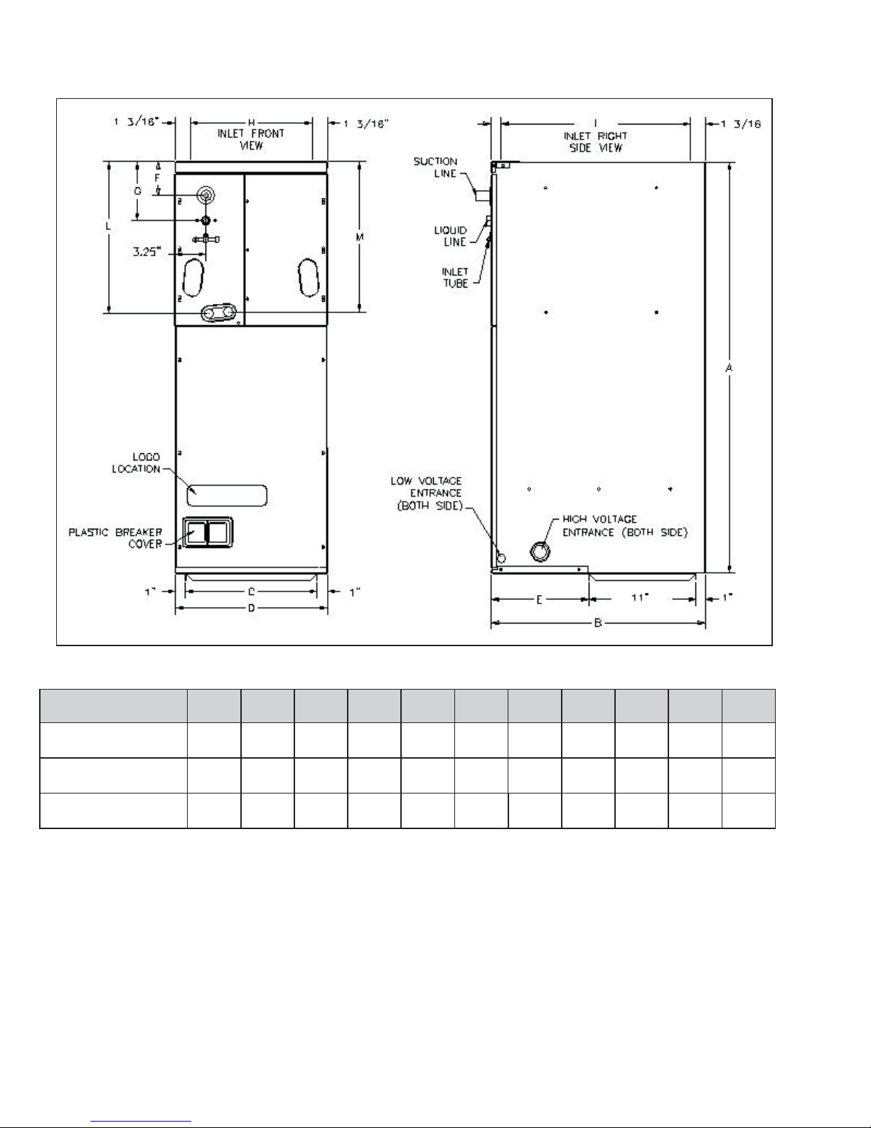
Model A B C D E F G
H
IJ
ARPF18241* 42 1/8" 22" 13 1/2" 15 1/2" 10" 14 1/2" 11 15/16" 13 1/8" 17 15/16" 2"
ARPF19311* 46 3/4" 22" 17 1/2" 19 1/2" 10" 14 1/2" 11 15/16" 17 1/8" 17 15/16" 2"
ARPF30301* 46 3/4" 22" 17 1/2" 19 1/2" 10" 14 1/2" 11 15/16" 17 1/8" 17 15/16" 2"
ARPF36361* 46 3/4" 22" 17 1/2" 19 1/2" 10" 14 1/2" 11 15/16" 17 1/8" 17 15/16" 2"
ARPF36421* 53 1/4" 24" 20" 22" 12" 14 1/2" 11 15/16"
ARPF37431* 53 1/4" 24" 20" 22" 12" 14 1/2" 11 15/16"
ARPF48601* 53 1/4" 24" 20" 22" 12" 14 1/2" 11 15/16"
ARPF49611* 53 1/4" 24" 20" 22" 12" 14 1/2" 11 15/16"
19 5/8"
19 5/8"
19 5/8"
19 5/8"
19 15/16" 1 13/16"
19 15/16" 1 13/16"
19 15/16" 1 13/16"
19 15/16" 1 13/16"
15
Page 16

PRODUCT SPECIFICA TIONS
s
ARPF
ARPF18241* ARPF19311* ARPF30301* ARPF36361*
Blower
Diameter 9 1/2" 9 1/2" 9 1/2" 9 1/2"
Width 6"6"8"6"
Coil Drain Connection FPT 3/4" 3/4" 3/4" 3/4"
Lineset Connection Size
Liquid 3/8" 3/8" 3/8" 3/8"
Suction 3/4" 7/8" 3/4" 3/4"
Electrical Data
Voltage 208 / 240 208 / 240 208 / 240 208 / 240
Min. Circuit Ampacity 2.1 / 2. 1 1.9 / 1.9 3.3 / 3.3 3.3 / 3.3
Max. Overcurrent Device ( amps) 15 / 15 15 / 15 15 / 15 15 / 15
Minimum VAC 197 197 197 197
Maximum VAC 253 253 253 253
Blower M otor
FLA 1.701.482.642.64
HP 1/3 1/4 1/3 1/3
Ship Weight (lbs)
120 155 144 164
ARPF36421* A RPF37431* ARPF48601* A RPF49611*
Blower
Diameter 10 5/8" 11 15/16" 10 5/8" 10 5/8"
Width 8" 10 11/16" 10 5/8" 10 5/8"
Coil Drain Connection FPT 3/4" 3/4" 3/4" 3/4"
Linese t C onn ection Size
Liquid 3/8" 3 /8" 3/8" 3/8"
Suction 7/8"7/8"7/8"7/8"
Electrical D ata
Voltage 208 / 240 208 / 240 208 / 240 208 / 240
Min. Circ uit Ampacity 3.7 / 3 .7 4.2 / 4 .2 5.4 / 5.4 5.4 / 5 .4
Max. O vercurrent D evice (a mp
Minim um VAC 197 197 197 197
Maximum VAC 253 253 253 253
Blower Motor
FLA 2.953.394.304.30
HP 1 /2 1/2 3/4 3/4
S hip W eight ( lbs)
15 / 15 15 / 15 15 / 15 15 / 15
160 195 192 192
16
Page 17

BLOWER PERFORMANCE DATA
ARPF
Model Speed
High 1155 1090 1025 950 895
ARPF18241* M ed . 940 890 860 815 755
Low 695 665 650 610 550
High 1135 1085 1025 965 915
ARPF19311* M ed . 860 825 780 750 680
Low 600 570 545 500 465
High 1385 1315 1240 1155 1065
ARPF30301* M ed . 1340 1290 1230 1140 1050
Low 1075 1030 980 910 840
High 1310 1240 1155 1090 1020
ARPF36361* M ed . 1270 1210 1140 1075 980
Low 1045 1005 955 885 805
High 1700 1660 1625 1545 1505
ARPF36421* M ed . 1500 1440 1400 1350 1345
Low 1330 1300 1250 1230 1220
High 2065 2000 1925 1860 1780
ARPF37431* M ed . 1685 1635 1550 1470 1410
Low 1490 1425 1345 1280 1205
High 2150 2120 2070 2000 1940
ARPF48601* M ed . 1940 1930 1905 1860 1790
Low 1610 1600 1590 1575 1550
High 2150 2105 2040 1970 1880
ARPF49611* M ed . 1960 1935 1895 1825 1750
Low 1670 1625 1585 1525 1455
CFM d e l i ve rd agai n st E x t e rn al St at i c P re ssu re
0.1" 0.2" 0.3" 0.4" 0.5"
Note: Assumes dry coil with filter in place; SCFM correction for wet coil = 4% (208V/240V)
17
Page 18

PRODUCT DIMENSIONS
J
ARUF
2 ȹ”
[7.30 cm]
Model A B C D E F G
ARUF172 916 4 2 1/8" 22" 13 1/2" 1 5 1/2" 1 0" 14 1/2" 11 15 /16" 13 1/8" 17 15/16" 2"
ARUF182 416 4 2 1/8" 22" 13 1/2" 1 5 1/2" 1 0" 14 1/2" 11 15 /16" 13 1/8" 17 15/16" 2"
ARUF193 116 4 6 3/4" 22" 17 1/2" 1 9 1/2" 1 0" 14 1/2" 11 15 /16" 17 1/8" 17 15/16" 2"
ARUF303 016 4 6 3/4" 22" 17 1/2" 1 9 1/2" 1 0" 14 1/2" 11 15 /16" 17 1/8" 17 15/16" 2"
ARUF363 616 4 6 3/4" 22" 17 1/2" 1 9 1/2" 1 0" 14 1/2" 11 15 /16" 17 1/8" 17 15/16" 2"
ARUF364 216 5 3 1/4" 24" 20" 22" 12" 14 1/2" 11 15 / 16"
ARUF374 316 5 3 1/4" 24" 20" 22" 12" 14 1/2" 11 15 / 16"
ARUF486 016 5 3 1/4" 24" 20" 22" 12" 14 1/2" 11 15 / 16" 19 5/8 " 19 15/16" 1 13/ 16"
ARUF496 116 5 3 1/4" 24" 20" 22" 12" 14 1/2" 11 15 / 16" 19 5/8 " 19 15/16" 1 13/ 16"
H
1 9 5/8"
1 9 5/8"
IJ
1 9 15/16" 1 13/ 16"
1 9 15/16" 1 13/ 16"
18
Page 19

PRODUCT SPECIFICA TIONS
ARUF172916 ARUF182416 ARUF193116 ARUF303016
Blower
Diameter 9 1/2" 9 1/2" 9 1/2" 9 1/2"
Width 6"6"6"8"
Coil Drain Connection FPT 3/4" 3/4" 3/4" 3/4"
Lineset Connection Size
Liquid 3/8" 3/8" 3/8" 3/8"
Suction 3/4" 7/8" 3/4" 3/4"
Electrical Data
Voltage 208 / 240 208 / 240 208 / 240 208 / 240
Min. Circuit Ampacity 2.1 / 2.1 2.1 / 2.1 1.9 / 1.9 3.3 / 3.3
Max. Overcurrent Device (amps) 15 / 15 15 / 15 15 / 15 15 / 15
Minimum VAC 197 197 197 197
Maximum VAC 253 253 253 253
Blower Motor
F LA 1.70 1.70 1.48 2.64
HP 1/3 1/3 1/4 1/3
Ship Weight (lbs)
110 120 155 144
ARUF
ARUF363616 ARUF364216 ARUF374316 ARUF486016 ARUF496116
Blower
Diameter 9 1/2" 10 5/8" 11 15/16" 10 5/8" 10 5/8"
Width 6" 8" 10 11/16" 10 5/8" 10 5/8"
Coil D ra in Connection FPT 3/4" 3/4" 3/4" 3/4" 3/4"
Lineset Conne ction Size
Liquid 3/8" 3/8" 3/8" 3 /8" 3/8"
Suction 3/4"7/8"7/8"7/8"7/8"
Electrical Data
Voltage 208 / 240 208 / 240 208 / 240 208 / 240 208 / 240
Min. Circuit Ampacity 3.3 / 3.3 3.7 / 3.7 4.2 / 4.2 5.4 / 5.4 5.4 / 5.4
Max. O ver current Device (amps ) 15 / 15 15 / 15 15 / 15 1 5 / 15 15 / 15
Minim um VAC 197 197 197 197 197
Maximum VAC 253 253 253 253 253
Blower Motor
FLA 2.642.953.394.304.30
HP 1/3 1/2 1/2 3/4 3/4
Ship Weight (lbs)
164 160 195 192 19 2
19
Page 20

BLOWER PERFORMANCE DATA
ARUF
Model Speed
High 1155 1090 1025 950 895
ARUF172916 Med. 940 890 860 815 755
Low 695 665 650 610 550
High 1155 1090 1025 950 895
ARUF182416 Med. 940 890 860 815 755
Low 695 665 650 610 550
High 1135 1085 1025 965 915
ARUF193116 Med. 860 825 780 750 680
Low
High 1385 1315 1240 1155 1065
ARUF303016 Med. 1340 1290 1230 1140 1050
Low 1075 1030 980 910 840
High 1310 1240 1155 1090 1020
ARUF363616 Med.
Low
High 1700 1660 1625 1545 1505
CFM d e li ve rd agai n st Exte rnal S tat i c P re ssu re
0.1" 0.2" 0.3" 0.4" 0.5"
600 570 545 500 465
1270 1210 1140 1075 980
1045 1005 955 885 805
ARUF364216 Med. 1500 1440 1400
Low 1330 1300 1250
High 2065 2000 1925 1860 1780
ARUF374316
ARUF486016
ARUF496116 Med. 1960 1935 1895 1825 1750
Note: Assumes dry coil with filter in place; SCFM correction for wet coil = 4% (208V/240V)
Med. 1685 1635 1550 1470 1410
Low 1490 1425 1345 1280 1205
High 2150 2120 2070 2000 1940
Med. 1940 1930 1905 1860 1790
Low 1610 1600 1590 1575 1550
High 2150 2105 2040 1970 1880
Low 1670 1625 1585 1525 1455
1350 1345
1230 1220
20
Page 21

PRODUCT DIMENSIONS
J
2 ȹ”
[7.30 cm]
ASPF
Model ABCDE F G H I J
ASPF183016*
ASPF303616*
ASPF313716*
ASPF426016*
4 6 3/ 4" 22" 17 1/2" 1 9 1/ 2" 10' 14 1 /2 " 11 15/16" 17 1/8" 17 15/ 16" 2 "
53 1/4" 24" 20" 22" 12" 19 5/8" 1 1 15/16" 19 5/8" 19 15/16" 1 13/ 16"
53 1/4" 24" 20" 22" 12" 19 5/8" 1 1 15/16" 19 5/8" 19 15/16" 1 13/ 16"
53 1/4" 24" 20" 22" 12" 19 5/8" 1 1 15/16" 19 5/8" 19 15/16" 1 13/ 16"
21
Page 22

PRODUCT SPECIFICA TIONS
AS P F183016* AS PF 303616* AS PF313716* ASPF 426016*
Blower
Diameter 9 1/2" 10 5/8" 10 5/8" 10 15/16"
Width 8" 10 5/8" 10 5/8" 10 11/16"
C o il D r a in Con n e ction FPT 3 /4" 3/4" 3/4 " 3/4 "
Lineset Connection Size
Liqu id 3/8" 3 /8 " 3 /8" 3/8"
S u ction 3/4" 7 /8 " 7 /8" 7/8"
Ele c trical Data
Voltag e 2 08 / 23 0 20 8 / 2 3 0 20 8 / 230 2 0 8 / 230
Min. Circ u it Ampacity 3. 6 / 3.6 3.8 / 3 .8 3.9 / 3.9 6.4 / 6. 4
Max. Overcurrent Device (am ps) 15 / 15 15 / 15 15 / 15 15 / 15
Minim um VAC 197 197 197 197
Maximum VAC 253 253 253 253
Blower Motor
FL A 2.9 3.0 3.1 5 .1
HP 1/2 3/4 3/4 3/4
Ship Weight (lbs)
125 176 176 195
ASPF
22
Page 23

BLOWER PERFORMANCE DATA
ASPF
Model
AS PF183016 3 920 900 850 840 815
AS PF303616 3 1165 1070 1020 960 915
AS PF313716 3 1165 1070 1020 960 915
Motor
Speed Tap
1 700 670 650 595 510
2 820 785 765 745 705
4 1075 1055 1015 975 960
5 1130 1115 1085 1040 1000
1 1060 86 5 600 515 420
2 1105 91 0 795 745 690
4 1285 1240 1195 1140 1100
5 1435 1395 1350 1315 1265
1 1060 86 5 600 515 420
2 1105 91 0 795 745 690
CFM del i ve rd agai n st E x t e rnal S tat i c P re ss ure
0.1" 0.2" 0.3" 0.4" 0.5"
4 1285 1240 1195 1140 1100
5 1435 1395 1350 1315 1265
1 1445 1275 1175 940 855
2 1545 1405 1325 1260 1145
AS PF426016 3
4
5
Notes: Assumes dry coil with filter in place; SCFM correction for wet coil = 4% (208/240V)
All ASPF models are shipped from the factory with the speed tap set on T4.
1660 1610 1555 1490 1415
1905 1870 1810 1750 1695
2115 2070 2000 1965 1915
Notes: Assumes dry coil with filter in place; SCFM correction for wet coil = 4% (208/240V)
All ASPF models are shipped from the factory with the speed tap set on T4.
23
Page 24

PRODUCT DIMENSIONS
J
ATUF
2 ȹ”
[7.30 cm]
Model A B C D E F G
ATUF182 416 4 2 1/8" 22" 13 1/2" 1 5 1/2" 1 0" 14 1/ 2" 11 15/16" 13 1/8 " 17 15/16" 2"
ATUF193 116 4 6 3/4" 22" 17 1/2" 1 9 1/2" 1 0" 14 1/ 2" 11 15/16" 17 1/8 " 17 15/16" 2"
ATUF303 016 4 6 3/4" 22" 17 1/2" 1 9 1/2" 1 0" 14 1/ 2" 11 15/16" 17 1/8 " 17 15/16" 2"
ATUF363 616 4 6 3/4" 22" 17 1/2" 1 9 1/2" 1 0" 14 1/ 2" 11 15/16" 17 1/8 " 17 15/16" 2"
ATUF364 216 5 3 1/4" 24" 20" 22 " 12" 14 1/2" 11 15 /16"
ATUF374 316 5 3 1/4" 24" 20" 22 " 12" 14 1/2" 11 15 /16"
ATUF486 016 5 3 1/4" 24" 20" 22 " 12" 14 1/2" 11 15 /16" 19 5/8" 19 15/ 16" 1 13/16"
H
1 9 5/8"
1 9 5/8"
IJ
1 9 15/16" 1 13/ 16"
1 9 15/16" 1 13/ 16"
24
Page 25

PRODUCT SPECIFICA TIONS
ATUF182416 AT UF193116 ATUF303016 ATUF363616
Blower
Dia met er 9 1/2 " 9 1/ 2" 9 1/2" 9 1/2"
Width 6"6"8"6"
Coil Dr ain Connection FPT 3/4" 3/4" 3/4" 3/4"
Lineset Connection Size
Liquid 3/8" 3/8" 3/8" 3/8"
Suction 7/8" 3/4" 3/4" 3/4"
Electrical Data
Volt age 208 / 240 2 08 / 24 0 2 08 / 240 208 / 240
Min. Circu it Ampa city 2.1 / 2.1 1.9 / 1.9 3.3 / 3.3 3.3 / 3.3
Max . Ove rc urrent Devi ce (amps) 15 / 15 15 / 15 15 / 15 15 / 15
Minimum VAC 19 7 197 197 197
Maximum VAC 253 2 53 25 3 25 3
Bl o wer Motor
FLA 1.70 1.48 2.64 2.64
HP 1/31/41/31/3
Ship Weight (lbs)
120 155 144 164
ATUF
ATUF364216 AT UF374316 ATUF486016
Blower
D ia m et e r 10 5/ 8" 11 15/16 " 1 0 5/8"
Wi dth 8" 10 11 /16" 10 5 / 8 "
Coil Dr ain Connection FPT 3/4" 3/4" 3/4"
Lineset Connection Size
Liquid 3/8" 3/8" 3/8"
Suction 7/8" 7/8" 7/8"
Electrical Data
Volt age 208 / 240 2 08 / 24 0 2 08 / 240
Min. Circu it Ampa city 3.7 / 3.7 4.2 / 4.2 5.4 / 5.4
Max. Overcurrent Device (amps) 15 / 15 15 / 15 15 / 15
Minimum VAC 19 7 197 197
Maximum VAC 253 2 53 25 3
Bl o wer Motor
FLA 2.95 3.39 4.30
HP 1/2 1/2 3/4
Ship Weight (lbs)
173 195 192
25
Page 26

BLOWER PERFORMANCE DATA
ATUF
Model Speed
High 1,155 1,090 1,025 950 895
ATUF182416 Med. 875 830 790 750 715
Low 640 610 570 535 490
High 1,135 1,085 1,025 965 915
ATUF193116 Med. 860 825 780 750 680
Low 600 570 545 500 465
High 1,455 1,385 1,330 1,205 1,090
ATUF303016 Med. 1,340 1,290 1,230 1,140 1,050
Low 1,075 1,030 980 910 840
High 1,345 1,290 1,230 1,150 1,070
ATUF363616 Med. 1,270 1,210 1,140 1,075 980
Low 1,045 1,005 955 885 805
High 1,700 1,680 1,645 1,610 1,535
ATUF364216 Med. 1,500 1,480 1,440 1,380 1,325
Low 135 1,320 1,275 1,230 1,195
CFM deliverd against External Static Pressure
0.1" 0.2" 0.3" 0.4" 0.5"
High 2,065 2,000 1,925 1,860 1,780
ATUF374316
ATUF486016
Note: Assumes dry coil with filter in place; SCFM correction for wet coil = 4% (208V/240V)
Med. 1,685 1,635 1,550 1,470 1,410
Low 1,490 1,425 1,345 1,280 1,205
High 2,135 2,080 1,985 1,900 1,805
Med. 1,975 1,935 1,875 1,775 1,675
Low 1,715 1,670 1,650 1,590 1,530
26
Page 27

PRODUCT DIMENSIONS
AWUF
Small Chassis
AWUF 18 & 24
A 36" A 36"
B 20 3/8" B 24"
C 16 1/8" C 21"
D 16" D 19 7/8"
E 11" E 15 7/8"
FILTER 14" X 18" X 1" FILTER 16" X 20" X 1"
Large Chassis
AWUF 30 BB & 3 6 BB
A 36"
B 24"
C 21"
D 19 7/8"
E 15 7/8"
FILTER 18" X 20" X 1"
Large Cha s s is
AWUF 30 BA & 36 BA
Large Chassis
AWUF 31,32 & 37
A 36"
B 24"
C 21"
D 19 7/8"
E 15 7/8"
FILTER 18" X 20 " X 1"
27
Page 28

PRODUCT SPECIFICA TIONS
AWUF[18-37]A*
Heating Cap acity
Ac tu al kW @ 240 volt s 3.0 4.8 7 . 3 3.0 4.8 7.3 9.8 3. 0 4.8 7.3 9.8
BTU /h @ 240 volts 1 0,240 16 ,3 90 24,92 5 10,240 16,3 90 24,925 33,460 10,2 40 16,390 24,925 33,460
Blow er
Diameter 9" 9" 9" 10" 10" 10" 10" 9" 9" 9" 9"
Width 6"6"6"6"6"6"6"8"8"8"8"
Coil Drain Connection FPT 3/4" 3/4" 3/4" 3/4" 3 /4" 3/4" 3/4" 3/4" 3/4" 3/4" 3/4"
Lineset Connection Siz e
Liquid 3/8" 3/8" 3/8" 3/8" 3/8" 3/8" 3/8" 3/8" 3/8" 3/8" 3/8"
Suction 5/8" 5/8" 5/8" 5/8" 5/8" 5/8" 5/8" 3/4" 3/4" 3/4" 3/4"
Electrical Data
Min. Cir cuit Ampacity* 15.1/17.3 26.7/23.3 39.7/34.2 15.1/17.3 26.7/23.3 39.7/34.2 52.7/45.6 15.5/17.6 27.0/23.6 40.0/34.9 53.0/46.2
Max. Overcurrent Device (amps)* 20/ 20 30/30 40/40 20/20 30/30 40/40 60/50 20/20 30/25 40/35 60/50
Minimum VAC 197 197 197 197 197 197 197 197 197 197 197
Maxi m um VAC 253 253 253 253 253 253 2 53 253 253 253 2 53
Blo wer Motor
FLA 1.30 1 .35 1.35 1.30 1.35 1.35 1.35 1.58 1.58 1.58 1.58
HP 1/5 1/5 1/5 1/5 1/5 1/5 1/5 1/3 1/3 1/3 1/3
Ship Weight (lbs)
* @ 240V/208V
AWUF18031**
84 84 84 84 84 84 84 93 93 93 93
AWUF18051
AWUF18081
AWUF24031**
AWUF24051
AWUF24081
AWUF24101
AWUF30031**
AWUF30051
AWUF30081
AWUF30101
AWUF310516
Heating Cap acity
Ac tu al kW @ 240 volt s
BTU /h @ 240 volts 1 6,390 24 ,9 25 33,46 0 16,390 24,9 25 33,460 16,390 24,9 25 33,460
Blow er
Diameter 10" 10" 10" 9" 9" 9" 10" 10" 10"
Width 8"8"8"8"8"8"8"8"8"
Coil Drain Connection FPT 3/4" 3/4" 3/4" 3/4" 3 /4" 3/4" 3/4" 3/4" 3/4"
Lineset Connection Siz e
Liquid 3/8" 3/8" 3/8" 3/8" 3/8" 3/8" 3/8" 3/8" 3/8"
Suction 3/4" 3/4" 3/4" 3/4" 3/4" 3/4" 3/4" 3/4" 3/4"
Electrical Data
Min. Cir cuit Ampacity* 30.1/26.8 43.1/38.1 56.2/49.4 27.0/23.6 40.0/34.9 53.0/46.2 30.1/26.8 43.1/38.1 56.2/49.4
Max. Overcurrent Device (amps)* 35/ 30 45/40 60/50 30/25 40/35 60/50 35/30 45/40 60/50
Minimum VAC 197 197 197 197 197 197 197 197 197
Maxi m um VAC 253 253 253 253 253 253 2 53 253 253
Blo wer Motor
FLA 4.1 4.1 4.1 1.58 1.58 1.58 4.1 4.1 4.1
HP
Ship Weight (lbs)
4.8 7.3 9.8
1/2 1/2 1/2
96 96 96
AWUF310816
AWUF321016
AWUF36051
4.8 7.3 9.8
1/3 1/3 1/3
96 96 96
AWUF36081
AWUF36101
AWUF37051
4.8 7.3 9.8
1/2 1/2 1/2
96 96 96
AWUF37081
AWUF37101
28
Page 29

PRODUCT SPECIFICA TIONS
AWUF[18-24]**16B*
He at ing Capaci t y
Actual kW @ 240 volts 4.8 7.3 3.0 4.8 7.3 9.8
BTU/h @ 240 vo lts 1 6, 390 24,9 25 10, 240 16, 390 24,925 33,460
Blow er
Diameter 9" 9" 10" 10" 10" 10"
Width 6" 6" 6"6"6"6"
Coil Drain Connection FPT 3/4" 3/4" 3/4" 3/4" 3/4" 3 /4"
Lineset Connection Siz e
Liquid 3/8" 3/8" 3/8" 3/8" 3/8" 3/8"
Suction 5/8" 5/8" 5/8" 5/8" 5/8" 5 /8"
Electrica l Data
Min. Circuit Ampacity* 26.6/23.3 39.6/34.6 15.1/17.3 26.7/23.3 39.7/34.2 52.7/45.6
Ma x. Overcu rrent De vice (a m ps)* 30/25 40/3 5 20/2 0 30/ 30 40 /40 60 /50
Mi nimum VAC 197 197 197 197 197 197
Maximum VAC 253 253 253 253 253 253
Blower Motor
FLA 1.30 1.30 1.30 1.35 1.35 1.35
HP 1/5 1/5 1/5 1/5 1/5 1/5
Ship Weight (lbs)
* @ 240V /208V
AWUF180516B*
84 84 84 84 84 84
AWUF180816B*
AWUF240316B*
AWUF240516B*
AWUF240816B*
AWUF241016B*
29
Page 30

BLOWER PERFORMANCE DATA
AWUF
Model Speed
AWUF18XX1/16A*
AW U F18 XX16B*
AWUF24XX1/16A*
AW U F24 XX16B*
AWUF30XX1/16A*
AW U F30 XX16B*
AWUF310516XX
High
Low
High
Low
High
Low
High
Low
High
Low
High
Low
T5
T4
T3
C FM deli ve rd agains t Exter na l St atic Pres su re
0.1" 0.2" 0.3" 0.4" 0.5"
750 730 690 650 595
710 700 690 635 585
755 715 670 615 545
740 700 655 595 535
880 845 810 770 735
845 815 780 745 705
900 870 835 795 760
865 835 800 765 725
1250 1195 1135 1085 1010
1110 1055 1020 955 905
1255 1120 1100 1020 950
1115 1010 990 900 820
875 865 830 805 765
1005 975 945 920 890
840 795 785 745 700
AWUF310816XX/
AWUF321016XX
AWUF36XX1/16A*
AW U F36 XX16B*
AW U F37 XX16A*
AW U F37 XX16B*
T2
T1
T5
T4
T3
T2
T1
Hig h 1280 1190 1110 1010 930
Low 1170 1100 1030 950 890
Hig h 1215 1145 1070 985 890
Low 1120 1065 1000 915 820
High
Low
T5
T4
T3
645 615 550 500 445
645 615 550 500 445
1090 1065 1040 1015 985
1005 975 945 920 890
840 795 785 745 700
645 615 550 500 445
645 615 550 500 445
1326 1284 1232 1181 1115
1086 1061 1028 996 950
1385 1205 1130 1045 950
1235 1180 1115 1040 955
1165 1120 1075 1025 945
T2
T1
Note:
Assumes dry coil with filter in place; SCFM correction for wet coil = 4% (208V/240V)
30
1050 1010 970 930 860
1050 1010 970 930 860
Page 31

WIRING DIAGRAMS
ACNF
HIGH VOLTAGE!
DISCONNECT ALL POWER BEFORE SERVICING OR INSTALLING THIS
UNIT. MULTIPLE POWER SOURCES MAY BE PRESENT . FAILURE TO
DO SO MAY CAUSE PROPERTY DAMAGE, PERSONAL INJURY OR DEATH.
Wiring is subject to change. Always refer to the wiring diagram on the unit for the most up-to-date wiring.
31
Page 32

WIRING DIAGRAMS
ADPF, ARPF, ARUF, A TUF
HIGH VOLTAGE!
DISCONNECT ALL POWER BEFORE SERVICING OR INSTALLING THIS
UNIT. MULTIPLE POWER SOURCES MAY BE PRESENT . FAILURE TO
DO SO MAY CAUSE PROPERTY DAMAGE, PERSONAL INJURY OR DEATH.
FL
FL
FL
FL
BL
YL
RD
BK
BK
L2L1 L1 L2
208/240 VOLTS
EM
LO
HI
SEE NOTE 1
3
TL
HTR1
HTR2
HTR3
HTR4
BK
M1
M2
RD
BK
TL
RD
TL
YL
TL
BL
BK
1
PU
RD
BL
M3
M7
M5
M6
M4
M8
R1
R2
YL
BL
BK
RD
2
3
RD
BL
4
5
BR
6
WH
7
8
9
L2
2
PLM
PLF
EBTDR
COM
2
NO
3
NC
M1
M2
PLM
PLF
FL
TLHTR2
FL
HTR1 TL
BK
RD
M1M2M3
R
RD
BK
BK
RD
L2L1
L2
L1
RD
BK
2
1
2
1
BK
RD
RD
BK
BK
BL
M4
WH
1
2
RD
3
PU
4
5
6
7
8
9
EQUIPMENT GROUND
EQUIPMENT GROUND
USE COPPER OR ALUMINUM WIRE
USE COPPER WIRE
GRD
3
4 5 678 9
3
4 5WH67489
PU
BR
BL
SEE
NOTE
BK
RD
L1
FL
FL
FL
YL
L2 L1 L2
HTR1
TL
BK
HTR2
TL
RD
HTR3
TL
RD
BK
M1
M3
M1
M4
M2
M2
R1
BK
RD
YL
BK
RD
BK
1
YL
PU
BL
R2
2
3
RD
BL
4
5
BR
6
WH
7
8
9
L1
1
PLM
1
PLF
RC
1
2
FL
HTR1
TL
BK
BK
L1 L2
BK
M1
R
M2
BK
BK
RD
BL
WH
1
2
RD
3
PU
4
5
6
7
8
9
ONE (1) ELEMENT ROWS TWO (2) ELEMENT ROWS THREE (3) ELEMENT ROWS FOUR (4) ELEMENT ROWS
NOTE: WHEN INSTALLING HEATER KIT, ENSURE SPEED TAP DOES NOT EXCEED MI NIMUM BLOWER SPEED ( M BS ) SP ECIFIED F OR THE AIRHANDLER/HEA T ER
KIT COMBINATION ON THIS UNIT'S S&R PLATE. AFTER INSTALLING OPTIONAL HEAT KIT, MARK AN "X" IN THE PROVIDED ABOVE.
MARK A CCORDING TO NUMBER OF HEATER ELEMENT RO WS INSTALLED. NO MARK INDICATES NO HEAT KIT INSTALLED.
TERMINAL BLOCK SHOW N
FOR 50HZ MO DELS ONLY
WH
RD GR
BL
BR
SR
SEE
NOTE
2
BR
WH
TR
GR
RD
BL
COPPER OR ALUMINUM
COPPER POWER SUPPLY
POWER SUPPLY
(SEE RATING PLATE)
(SE E RATING PLATE)
USE MIN. 75°C FIELD WIRE
USE MIN. 75°C FIELD WIRE
IF RE PL AC E M ENT OF THE O R IG INA L WIRES
SUPPLIED WITH THIS ASSEMBLY IS NECESSARY,
USE WIRE THAT CONFORMS TO THE
NATIONAL ELECTRIC CODE.
XFMR-R
XFMR-C
RD
BL
SPEEDUP
THREE SPEED MOTOR WIRING
(SELE CT M ODELS ONL Y)
G
R
C
EBTDR
SEE NOTE 3
SEE NOTE 5
K1
COM
K1
M1
M2
RD
NO
NC
SEE
NOTE
R G
BK
PU
RD
BK
PU
3
(M1) RD LOW
BL
(M2)
MEDIUM
(COM) BK
(TR 1)
PU
HIGH
PU
BR
RC
C
EM
3 SPEED
1 2
5
BL
24V
RD
3
4
RD
SEE NOTE 1
240
TR
BL
RC
RD
COLOR CODE
BK
BLACK
RD
RED
YELLOW
BLYLBLUE
COMPONENT CODE
EM
EVAPORATOR MOTOR
RC
RUN CAPACITOR
SR
PU
BK
RD
BR
EM
BR
Notes:
1) Red wires to be on transformer terminal "3" for 240 volts and on terminal "2" for 208 volts.
2) See composite wiring diagrams in installation instructio ns
for proper low voltage wiring connections.
3) Confirm speed tap selected is appropriate for application. If speed tap needs
to be changed, connect appropriate motor wire (Red for low, Blue for medium,
and Black for high speed) on "COM" connection of the EBTDR.
Inactive motor wires should be connected to "M1 or M2" on EBTDR.
4) Brown and white wires are used with Heat Kits only.
5)
EBTDR has a 7 second on delay when "G" is energized and a 65 second off
delay when "G" is de-energized.
STRAIN RELIEF
RRELAY
EBTDR
ELECTRONIC BLOWER TIME
DELAY RELAY
EBTDR
24V
4
5
5
4
WH6BR
GREEN
GR
PURPLE
PU
BROWN
BR
WHITEWH
C
EBTDR
PLF
BL
WIRING CODE
FACTORY WIRING
HIGH VOLTAGE
LOW VOLTAGE
FIELD WIRING
HIGH VOLTAGE
LOW VOLTAGE
TR
TRANSFORMER
FEMALE PLUG CONNECTOR
PLF
MALE PLUG CONNECTOR
PLM
FL FUSE LINK
THERMAL LIMIT
TL
HTR HEAT ELEMENTS
GR
NOTE 2
0140M00037
Wiring is subject to change. Always refer to the wiring diagram on the unit for the most up-to-date wiring.
32
Page 33

WIRING DIAGRAMS
ADPF, ARPF, ARUF, A TUF
HIGH VOLTAGE!
DISCONNECT ALL POWER BEFORE SERVICING OR INSTALLING THIS
UNIT. MULTIPLE POWER SOURCES MAY BE PRESENT . FAILURE TO
DO SO MAY CAUSE PROPERTY DAMAGE, PERSONAL INJURY OR DEATH.
FL
BL
YL
RD
BK
L2L1 L1 L2
208/240 VOLTS
EM
EM
HI
HI
LO
LO
3
3
FL
HTR1
HTR2
FL
HTR3
FL
HTR4
BK
RD
M1
M2
BK
RD
M1
M1
M2
M2
SEE NOTE 1
SEE NOTE 1
TL
TL
TL
TL
BL
PU
M5
M3
M4
M6
R1
YL
BL
BK
RD
3 2
NC
NC
BK
RD
YL
EBTDR
EBTDR
COM
COM
PLF
BK
1
2
BL
M7
M8
R2
3
RD
BL
4
5
BR
6
WH
7
8
9
L2
2
PLM
NO
NO
PLM
PLF
FL
TL
HTR2
FL
TL
HTR1
BK
RD
M1M2M3
R
RD
BK
BK
RD
L2L1
L2
L1
RD
BK
23
1
2
1
BK
BK
RD
RD
RD
BK
BK
1
2
RD
3
PU
BL
M4
WH
4
5
6
7
8
9
TWO (2) ELEMENT ROWS THREE (3) ELEMENT RO W S FOUR (4) ELEMENT ROWS
EQUIPMENT GROUND
USE COPPER WIRE
GRD
4 5 678 9
4 5WH6789
3
PU
PU
BL
BL
WH
BR
BR
SEE
SEE
NOTE 4
NOTE 4
BK
L1
RD
FL
FL
FL
YL
BK
L2 L1 L2
TL
HTR1
HTR2
HTR3
BK
M1
M2
RD
BK
TL
RD
TL
RD
M3
M1
M4
M2
R1
YL
BK
RD
BK
1
YL
PU
BL
R2
2
3
RD
BL
4
5
BR
6
WH
7
8
9
L1
1
PLM
1
PLF
RC
RC
1
1
2
2
FL
TL
HTR1
BK
BK
L1 L2
BK
M1
R
M2
BK
BK
BL
WH
RD
1
2
RD
3
PU
4
5
6
7
8
9
ONE (1) ELEMENT ROWS
NOT E: W HEN INSTALLING HEATER KI T, ENSURE SPEED TAP DOES NOT EX CEED MINIMUM BL OWER SPEED (MBS) SPECIFIED FOR THE AIRHANDLER/HEATER
KIT COMBINAT ION ON TH I S UNIT'S S&R PL ATE. A F TE R INSTALLING OPTIONAL HE AT KIT, MARK A "X" IN THE PROV IDED ABOV E.
MARK ACCORDING TO NUMBER OF HEA TER ELEMENT ROWS INSTALLED. NO MARK INDICA TES NO HEAT KIT INSTALLED.
BL
SEE NOTE 2
RD GR
WH
TE RMINAL BLOCK SHOW N
FOR 50HZ MODELS ONLY
BR
SR
BR
BR
WH
WH
TR
GR
RD
BL
G
EBTDR
R
XFMR-R
RD
XFMR-C
C
BL
SPEEDUP
COPP ER PO WER SUPPLY
(SEE RATING PLATE)
USE MIN. 75°C FIELD WIRE
THREE SPEED MOTOR WIRING
(SELECT MODELS ONLY)
SEE NOTE 3
IF REPLACEMENT OF THE ORIGINAL WIRES
SUPPLIED WITH THIS ASSEMBLY IS NECESSARY
USE WIRE THAT CONFORMS TO THE
NATIONAL ELECTRIC C OD E.
SEE NOTE 5
NO
K1
COM
K1
NC
M1
M2
BK
NOTE 3
SEE
RD
PU
(TR 1)
PU
RD
(COM) RD LOW
(M2)
BL
(M1) BK
PU
RC
BK
MEDIUM
HIGH
BR
PU
C
EM
3 SPEED
123
5
24V
BL
RD
4
RD
SEE NOTE 1
240
TR
BL
RC
BR
BR
R G
EBTDR
24V
4
5
5
RD
WH6BR
COLORCODE
BK
BLACK
RD
RED
YELLOW
BLYLBLUE
GREEN
GR
PURPLE
PU
BROWN
BR
WHITEWH
COMPONENT CODE
EM
EVAPORATOR MOTO R
RC
RD
PU
N
OTES:
BK
EM
1) RED WIRES TO BE ON TRANSFORMER TERMINAL "3 " FOR 240 VOLTS AND
ON TERMINAL "2" FOR 208 VOLTS
2) SEE COMPOSITE WIRING DIAGRAMS IN INSTALLATION INSTRUCTIONS FOR PROPER
LOW VOLTAGE WIRING CONNECTIO NS
3) CONFIRM SPEED T AP SEL ECT ED IS APPROPRIATE FOR APPLICATION . IF SPEED TAP
NEEDS TO BE CHANGED, CONNECT APPROPRIATE MOTOR WIRE (RED FOR LOW,
BLUE FOR MEDIUM,AND BLACK FOR HIGH SPEED) ON "COM" CONNECTION OF THE EBTDR
INACTIVE MOTOR WIRES SHOULD BE CONNECTED TO "M1 OR M2" ON EBTDR.
4) BROWN AN D WH ITE WIRES ARE USED WITH HEAT KITS ONL Y.
5) EBTDR HAS A 7 SEC O N D O N DE LAY WHEN "G" IS ENERGIZED AND A 65 SECOND OFF
DELAY WHEN "G" IS DE-ENERGIZED.
RUN CAP ACITOR
SR
STRAIN RELIEF
RRELAY
EBTDR
ELECTRONIC BLOWER TIME
DELAY RELAY
C
EBTDR
4
PLF
BL
WIRING CODE
FACTORY WIRING
HIGH VOLT AGE
LOW VOLTAGE
FIELD WI RING
HIGH VOLT AGE
LOW VOLTAGE
TR
TRANSFORMER
FEMALE PLU G CONNECTOR
PLF
MALE PLU G CONNECT OR
PLM
FL FUSE LINK
TL
THERMAL LI MIT
HTR HEAT ELEMENTS
GR
0140M00170-E
Wiring is subject to change. Always refer to the wiring diagram on the unit for the most up-to-date wiring.
33
Page 34

WIRING DIAGRAMS
A
AEPF
HIGH VOLTAGE!
DISCONNECT ALL POWER BEFORE SERVICING OR INSTALLING THIS
UNIT. MULTIPLE POWER SOURCES MAY BE PRESENT . FAILURE TO
DO SO MAY CAUSE PROPERTY DAMAGE, PERSONAL INJURY OR DEATH.
R
BK
6
W1
PJ4
W1
FL
FL
HTR2
FL
HTR3
FL
HTR4
BL
BK
M1
Y
M2
BK
R
L2L1 L1 L2
TO LOW V OLTAGE
TERMINAL BOARD
PL2
YCON
IN4005
DIODE
Y1YY2
SEE NOTE 1
FACT ORY WI RI NG
HIGH VOLTAGE
LOW VO LTAGE
FIELD W IRIN G
HIGH VOLTAGE
LOW VO LTAGE
THERM AL LIMIT
TL
HEAT ELEMENT
HTR
RELAY
R
TLHTR1
TL
TL
TL
R
M3
M4
R1
Y
BK
R
W
BK
R
Y
BL
PU
M5
M6
BL
SEE
NOTE 4
NOTE DIODE
ON VSTB
G
*SEE N O TE 7
IRING CODE
BL
M7
M8
R2
W
1
1PL2
BK
R
PL1
4
PL2
C
0140A00000P
1
2
3
BL
4
5
BR
6
7
8
9
FL
TL
HTR1
BK
BK
1
2
R
PU
BK
L1 L2
M1
R
M2
BK
BK
BL
W
R
3
4
5
6
7
8
9
ONE (1) ELEMENT RO WS TWO (2) ELEMENT ROWS THREE (3) ELEMENT ROWS FOUR (4) ELEMENT ROWS
AFTER INSTALLING OPTIONAL HEAT KIT, MARK AN "X" IN THE PROVIDED ABOVE.
* SEE NOTE 7
LOW VOLTAGE
FIELD CO N NECTION
BOX
PN. B1368270 REV. A
J1
COPPER
POWER SUPPLY
(SEE RATING PLATE)
CONTROLS SHOW N WITH UTILITIES IN "ON" POSITION AND THERMOSTAT IN "OFF" POSITION.
IF REPLAC EM ENT OF THE ORIGINAL WIRES SUPPLIED WITH THIS ASSEMBLY IS NECESSAR Y, USE 105°C. W IRE. SIZE TO CONFORM TO THE NATIONA L ELECTRIC CODE.
R
YCON
HUM
PJ6
DS1
CONDENSER
OT2
OT1
COM W2OED
W1
HEATPUMP
W2
PJ2
PJ4
HEATER
W1
W2
W
24 VAC
CR
BR
BL
R
Y1
J3J2
TO
CONDENSER
W/W2
OTC OT1 COT2OE\W1
OUTDO OR
THERMOST
TS
R Y1 G
Y/Y2
HUMIDISTAT
HUM
YCON
R
R
Y
BL
O
BR
BL
THERMOSTAT
W1
O
W2 R
C
W2
Y
O
BL
BR
BR
W
BR
R
PU
G
Y
EQUIPMENT GRO UND
FL
TL
HTR2
FL
TL
HTR1
BK
R
M1M2M3
R
R
BK
BK
R
L2L1
MARK ACCORDING TO NUMBER OF HEATER ELEMENT ROWS INSTALLED
R
BK
BK
BL
M4
W
1
2
R
3
PU
4
5
6
7
8
9
NO MARK INDICATES NO HEAT KIT INSTALLED
BK
R
L1
FL
FL
FL
Y
L2 L1 L2
TL
HTR1
HTR2
HTR3
BK
M1
M2
BK
R
BK
TL
R
TL
Y
R
BL
M3
M1
M4
M2
R2
R1
Y
BK
R
TO
Y1C
Y/Y2
G
O
BL
PUW
RYG
O
R
BL
BR
W
USE COPPER WIRE
BK
PL1
PL2
1R23
312
BR
SEE NOTE 8
4567 89
456789
BK
BL
R
240
208
COM
1
2
3
R
W
BK
R
EM
TR
4
BL
R
24V
5
BL
G
N
OTES:
1. FOR HEAT PUM P APPLICATIONS REMOVE ORANGE JUMP ER WIRE BETWEEN O & Y1.
2. FOR TWO S TAGE ELECTRIC HEAT APPLICATIONS CUT PJ4. (USE ONLY ON 15 & 20 KW MODE LS).
3. FOR OUTDOOR THERMOSTAT OPERATION OF SECOND STAGE HEAT, CUT PJ2 & ADD OT18-60 TO OTC & OT2.
4. FOR SINGLE STAGE COOLING APPLICATIONS CONNECT TH ERMOST AT TO Y/Y2 ONLY,
TAPE OR REMOVE Y1 CONNECTION. CONNECT CONDENSING UNIT TO YCON & C.
5. W HEN HUMIDSTAT IS PROVIDED CUT PJ 6. THER MOSTAT OPEN S ON HUMIDITY RISE.
6. RED WIRES TO BE O N TRANSFORMER TERMINAL 3 FOR 2 40 VOLTS AND ON TERMINAL 2 FOR 208 VOLTS.
7. SE E COMPOSITE WIRING DIAGRAMS IN I NSTALLATION INSTRUCTIONS FOR PROPER LO W VOLTAGE
CONNECTIONS AN D DETAILS ON CO MPATIBLE THERMOS TATS AND THEIR CONNECTIONS.
8. DISCARD ORIGINAL "PL1" PLUG CONNECTOR WHEN INSTALLING OPTIONAL HEAT KIT.
SEE NOTE 5
PJ6
HUM
R
SEE NOTE 3
PL1
PL2
5 PL2
W2
PJ2
2OT1
PJ2,PJ4,PJ6
TR
W WHITE
R
Y
BL
EM
PL
FL FUSE LINK
BK
1
2
PU
3
R
BL
4
5
BR
6
W
7
8
9
2
2
EM
2
3
1
5
24 VOLT
4
OT
OT
O
C
W2W E
SEE NOTE 2
COLOR COD E
BLACKBK
RED
YELLOW
BLUE
EVAPORATOR MOTOR
PLUG
PRO GRA M JU MPER
VARIABLE SPEED TRANSFORMERVSTB TR
PU PURPLE
0
PK
TERMINAL BOARD
GREENG
BROWNBR
ORANGE
PINK
COMP
208/240 VOLTS
ONENT CODE
Wiring is subject to change. Always refer to the wiring diagram on the unit for the most up-to-date wiring.
34
Page 35

WIRING DIAGRAMS
A
A
AEPF******CA
HIGH VOLTAGE!
DISCONNECT ALL POWER BEFORE SERVICING OR INSTALLING THIS
UNIT. MULTIPLE POWER SOURCES MAY BE PRESENT . FAILURE TO
DO SO MAY CAUSE PROPERTY DAMAGE, PERSONAL INJURY OR DEATH.
RD
BK
6
W1
PJ4
W1
FL
HTR 1
FL
HTR 2
FL
HTR 3
FL
HTR 4
BL
RD
BK
M1
YL
M2
BK
RD
L1L1 L2 L2
TO LOW VOLTAGE
TERMINAL BOARD
PL2
YCON
IN4005
DIODE
Y1
Y Y2
SEE NOTE 1
FACT ORY WIRING
HI GH VOLT AGE
LOW VOLTAGE
FIELD WI RING
HI GH VOLT AGE
LOW VOLTAGE
TL
THERMAL LI MIT
HTR
HEAT ELEMENT
RELAY
R
TL
TL
TL
TL
PU
M3
M5
M6
M4
R1
YL
BL
BK
RD
NOTE DIODE
ON VSTB
WIRING CODE
BK
RD
YL
BL
BL
M7
M8
R2
1
1
SEE
NOTE 4
G
*SEE NOTE 7
PL 1
BK
RD
BL
BR
WH
PL1
PL2
4
PL2
C
0140A00041-B
1
2
3
4
5
6
7
8
9
FL
HTR 1
BK
R
BK
L1 L2
* SEE NOTE 7
LOW VOLTAGE
FIELD CONNECTION
BOX
PN. B1368270 REV. A
J1
VSTB
TL
BK
M1
M2
BK
RD
PL 1
1
BK
2
RD
PU
BL
WH
3
4
5
6
7
8
9
ONE (1) ELEMENT ROWS TWO (2) ELEMENT ROWS THREE (3) ELEMENT ROWS FOUR (4) ELEMENT ROWS
FTER INSTALLING OPTIONAL HEAT KIT, MARK A "X" IN THE PROVIDED ABOVE.
TO
FOR HEAT
PUMPS ONLY
HUM
OT2
OT1
PJ2
PJ6
PJ4
WH
BR
DS1
J3J2
CONDENSER
O
RD
R
YCON
COM W2OED
W1
W2
W1
W2
CR
BL
RD
YL
CONDE NSER
W/W2
HEATPUMP
OTC OT1 COT2OE\W1
THERMOST
OUTDOOR
HEATER
TS
O
24 VA C
RY1G
Y1
Y/Y2
HUMIDISTAT
HUM
RD
OR
YCON
R
BL
WH
BR
BL
THERMOSTAT
W1
C
W2
W2
YL
OR
BL
BR
BR
BR
RD
PU
GR
YL
FL
TL
HTR 1
FL
TL
HTR 2
RD
BK
M1M2M3
R
BK
RD
BK
RD
L1 L2
MARK ACCORDING TO NUMBER OF HEATER ELEMENT ROWS INSTALLED
BK
RD
M4
WH
PL 1
1
BK
2
RD
3
PU
BL
4
5
6
7
8
9
NO MARK INDICATES NO HEA T KIT INSTALLED
TO
Y1C
Y/Y2
R
G
SEE NOT E 8
BL
TR
RD
240
1
208
2
3
COM
PUWHBL
RDYLGR
BK
PL1
PL2
1RD23
312
456789
456789
BK
RD
WH
BK
EQUIPMENT GROUND
USE COPPER WIRE
RD
BR
RD
BL
BR
WH
EM
COPPER
POWER SUPPLY
(SEE RATING PLATE)
CONTROLS SHOWN WITH UTILITIES IN "ON" POSITION AND THERMOSTAT IN "OFF" POSITION.
FL
TL
BK
TL
RD
TL
RD
YL
BL
M3
M1
M4
M2
R2
R1
YL
BK
RD
PL 1
1
BK
2
PU
3
RD
4
BL
5
BR
6
WH
7
8
9
RD
BK
L1 L2 L2L1
HTR 1
FL
HTR 2
FL
HTR 3
YL
BK
M1
M2
BK
RD
208/240 VOLTS
PL1
2
PL2
2
EM
EQUIPMENT GROUND
USE COPPER WIRE
1
2
3
TR
5
24 VOLT
4
BL
RD
24V
5
BL
SEE NOTE 5
PJ6
HUM
R
SEE NOTE 3
GR
EQUIPMENT GROUND
USE COPPER WIRE
PJ2,PJ4,PJ6
NOTES:
1. FOR HEAT PU
2. FOR TWO STAGE ELECTRIC HEAT APPLICATIONS CUT PJ4. (USE ONLY ON 15 & 20 KW MODELS).
3. FOR OUTDOOR THERMOSTAT OPERATION OF SECOND STAGE HEAT, CUT PJ2 & ADD OT18-60 TO OTC & OT2.
4. FOR SINGLE STAGE COOLING APPLICATIONS CONNECT THERMOSTAT TO Y/Y2 ONLY,
5. WHEN HUMIDSTAT IS PROVIDED CUT PJ6. THERMOSTAT OPENS ON HUMIDITY RISE.
6. RED WIRES TO BE ON TRANSFORMER TERMINAL 3 FOR 240 VOLTS AND ON TERMINAL 2 FOR 208 VOLTS.
7. SE E COMPOSITE WIRING DIAGRAMS IN INSTALLATION INSTRUCTIONS FOR PROPER LOW VOLTAGE
8. DISCARD ORIGINAL "PL1" PLUG CONNECTOR WHEN INSTAL LING OPTIONAL HEAT KIT.
MP APPLICATIONS REMOVE ORANGE JUMPER WIRE BETWEEN O & Y1.
TAPE OR REMOVE Y1 CONNECTION. CONNE CT CONDENSING UNIT TO YCON & C.
CONNECTIONS AND DETAILS ON COMPATIB LE THERMOSTATS AND THEIR CONNECTIONS.
4
5
PL2
W2
PJ2
OT
OT
2OT1
C
COLOR CODE
WH WHITE
BLACKBK
RD
RED
YL
YELLOW
BLUE
BL
EM
EVAPORATOR MOTOR
PL
PLUG
PROGRAM JUMPER
VARI ABLE SPEED TRANSFORMERVSTB TR
TERMINAL BOARD
FL FUSE LINK
O
SEE NOT E 2
PU PURPLE
0R
PK
W2W E
GREENGR
BROWNBR
ORANGE
PINK
COMPONENT CODE
Wiring is subject to change. Always refer to the wiring diagram on the unit for the most up-to-date wiring.
35
Page 36

WIRING DIAGRAMS
ASPF******AA
HIGH VOLTAGE!
DISCONNECT ALL POWER BEFORE SERVICING OR INSTALLING THIS
UNIT. MULTIPLE POWER SOURCES MAY BE PRESENT . FAILURE TO
DO SO MAY CAUSE PROPERTY DAMAGE, PERSONAL INJURY OR DEATH.
BK
TL
HTR1
FLFLFL
BK
TL
HTR1
FLFLFL
TLHT R2
FL
FL
4
6
1
3
2
BL
BK
RD
BL
RD
YL
TLTLTL
HTR3
HTR2
FL
RD
TL
HTR2
M7R2M8
BL
M5
PU
M3
RD
HTR4
BK
M1
BL
YL
2
BL
BK
RD
PU
BL
YL
M2
M1
TL
HTR3
M4
M3
RD
BK
M1
M2
YL
RD
897
5
BR
WH
M6
BL
BK
R1
M4
M2
RD
56341
BR
R2
R1
BK
RD
YL
RD
BK
BK
978
WH
BK
RD
YL
RD
BK
L2L1 L1 L2
L2 L1 L2
L1
COM
NO NC
EBTDR
G
R
XFMR-C
XFMR-R
C
C
EM
1
243
5
CR
7 4
2
2
L2
PLM
PLF
B
SEE NOTE 1
208/2 40 VOLTS
EM
C LGN
PLF
PLM
1
1
L1
3
2
1
PLF
4
5
5
6
24V
4
TR
WIRING COD E
HIGH VOLTAGE
FACTORY W IRI NG
PURPLE
GREEN
W2R W1C G 4Y1 OY2 1DH 32 5
PU
GR
COLOR CODE
RED
BLACK
BKRDBL
FEMALE P L UG CONNECTOR
MALE PL U G CONN E CT OR
THERMAL LIMIT
TRANSFORMER
FL FUSE LINK
TL
TR
LOW VOLTAGE
HIGH VOLTAGE
LOW VOLTAGE
FIELD WIR ING
PLF
HTR HEAT ELEMENTS
PLM
BROWN
WHITEWH
BR
YELLOW
YL
BLUE
RELAY
DELAY RELAY
EVAPORATO R M O TO R
ELECTRONIC BLOWER TIME
TERMINA L BOARD
R
TB
COMPONENT CODE
EM
CR CONT ROL RELAY
EBTDR
for proper low voltage wiring connections.
Notes:
3) Confirm speed tap selected is appropr iate fo r application. If speed tap needs
1) Red wires to be on t ransformer t erminal "3" for 240 volts and on terminal "2" for 208 volts.
2) See composite wiring diagrams in installation instructions
0140A00034
to be changed, connect red wire from terminal 4 of CR relay to appropriate t ap
at TB
4) Brown and white wires are used with He at Kits only.
NC GL
EM
21 43 5
NOTE 4
6
2
453
1
BK
RD
PU
RD
HTR1 TL
BL
BK
M3
M1
BK
RD
897
WH
M4
RD
M2
BK
RD
R
BK
L2L1
EQUIPMENT GROUND
USE COPPER WIRE
EQUIPMENT GROUND
USE COPPER OR ALUMINUM WIRE
4 5 678 9
GRD
3
2
RD
L2
1
BK
L1
PLM
SEE
6789
WH
BR
4 5
BL
3
2
RD
1
BK
SEE NOTE 1
RD
BK
BK
BL
240
TR
4
RD
24V
5
1 2 3
BL
C
RD
RD
PLF
RD
BL
NOTE 3
SEE
BL
BK
RD
4
1
BK
BK
TL
HTR1
FL
563
2
RD
PU
BL
M1
M2
R
BK
987
WH
RD
BK
BK
ONE (1) ELEMENT ROWS TWO (2) ELEM ENT ROW S THREE (3) ELEMENT ROWS FOUR (4) ELEMENT ROWS
L1 L2
Wiring is subject to change. Always refer to the wiring diagram on the unit for the most up-to-date wiring.
36
17
41 32 5DH
FOR 50HZ MODELS ONLY
TERMINAL BLOCK SHOWN
BR
WH
SEE NOTE 2
MARK ACCO RDING TO NUMBER OF HEATER ELEMENT ROWS INSTALLED. NO MARK INDICATES NO HEAT KIT INSTALLED.
KIT CO MBINATION ON THI S UNIT'S S&R PL AT E. AFTER I NSTALLING OPTIONAL HEAT KIT, MARK AN "X" IN THE PROVIDED ABOVE.
RCGW1W2 Y2Y1 O
RD
NOTE: WHEN INSTALLIN G HEATER KIT, ENSURE SPEED TAP DOE S NOT EXCEED MINIMUM BLOWER SPEED (MBS) SPECIFIED FOR THE AIRHAND LER/HEAT ER
RD
BL
4
BL
CR
BL
COM
GR
RD
XFMR-R
A B
RD
GR
RD
RD
BL
NO NC
EBTDR
R
XFMR-C
BL
G
C
POWER SUPPLY
(SEE RATING PLATE)
(SEE RATING PLATE)
COPPER OR ALUMINUM
COPPER POWER SUPPLY
USE MIN. 75°C FIELD WIRE
GR
USE MIN. 75°C FIELD WIRE
IF REPLACEMENT OF THE OR IGINA L W IRES
USE W IRE THAT CONF O RMS TO THE
SUPPLIED WITH THIS ASSEMBLY IS NECESSARY,
NA TIONAL ELECT RIC CODE.
Page 37

WIRING DIAGRAMS
4
5
3
2
1
PLM
BK
RD
BK
YL
TL
TLTLTL
HTR3
HTR2
HTR1
FL
FL
FL
FL
FL
FL
PLM
BK
RD
TL
TL
TL
HTR2
HTR1
HTR3
FL
FL
FL
PLM
RD
TLHT R2
HTR1 TL
FL
1
PLM
BK
BK
TL
HTR1
BL
BL
PU
RD
HTR4
BK
BL
2
3
1
BK
RD
PU
BL
YL
RD
BK
YL
2
3
1
BK
RD
PU
BK
BK
4
3
2
RD
PU
BL
M1
BK
6
897
BR
BL
RD
WH
M7R2M8
M6
M5
R1
M4
M3
M1
M2
YL
RD
4
5
BR
BL
R2
M2
M1
M4
R1
M3
M1
M2
BK
RD
4
5
BL
M4
M3
M1
M2
R
RD
5
6
M2
R
BL
RDBKYL
RD
BK
BK
6
BK
WH
978
WH
BK
RD
YL
RD
6
897
WH
RD
BK
RD
BK
9
8
7
RD
BK
BK
ASPF******BA
HIGH VOLTAGE!
DISCONNECT ALL POWER BEFORE SERVICING OR INSTALLING THIS
UNIT. MULTIPLE POWER SOURCES MAY BE PRESENT . FAILURE TO
DO SO MAY CAUSE PROPERTY DAMAGE, PERSONAL INJURY OR DEATH.
C
EM
1
243
5
5
FOUR (4) ELEMENT ROWS
L2L1 L1 L2
2
2
L2
PLM
PLF
208/240 VOLTS
L2 L1 L2
L1
EQUIPMENT GROUND
EQUIPMENT GROUND
USE COPPER OR ALUMINUM WIRE
L2
L1
L2L1
FOR 50HZ MODELS ONL Y
TERMINAL BLOCK SHOWN
SEE NOTE 2
ONE (1) ELEM ENT ROWS TWO (2) ELEMENT ROWS THREE (3) EL EMENT ROWS
MARK ACCORDING TO NUMBER OF HEATER ELEMENT ROWS INSTALLED. NO MARK INDICATES NO HEAT KIT INSTALLED.
KIT COMBINATION ON THIS UNIT'S S&R PLATE. AFTER INSTALLING OPTIONAL HEAT KIT, MARK AN "X" IN THE PROVIDED ABOVE.
L1 L2
EM
C LGN
PLF
PLM
1
1
L1
6789
USE COPPER WIRE
4 5
4 5 678 9
GRD
3
2
23
RD
1
1
BK
PLF
PLM
W2R W1CG 4Y1 OY2 1DH 32 5
RD
WH
BR
BK
NOTE: WHEN INSTALLING HEATER KIT, ENSURE SPEED TAP DOES NOT EXCEED MINIMUM BLOWER SPEED (MBS) SPECIFIED FOR THE AIRHANDLER/HEATER
4
CR
2
FEMALE PLUG CONNECTOR
MALE PLUG CONNECTOR
WIRING CODE
FACTORY WIRING
TRANSFORMER
TR
FIELD WIRING
HIGH VOLTAGE
LOW VOLTAGE
HIGH VOLTAGE
LOW VOLTAGE
PLF
PLM
3 1
SEE NOTE 1
3
2
1
NOTE 4
SEE
BL
RD
PLF
4
5
5
6
24V
4
TR
PU
W2R W1C G 4Y1 OY2 1DH 32 5
HOLDER
FUSE
SEE NOTE 1
3
RD
1 2
BK
BK
SEE
NOTE 3
WH
4
CR
BR
WH
GR
WH
BL
RD
WHITE
BROWN
PURPLE
GREEN
PU
BR
GR
WH
COLOR CODE
RED
BLACK
YELLO W
BLUE
RELAY
EVAPORATOR MOTOR
BKRDBL
240
TR
4
24V
5
C
RD
TERMINAL BOARD
YL
BL
BL
R
TB
COMPONENT CODE
EM
YL
PU
BR
21 43 5
WH
OR
BL
FUSE
HOLDER
RD
BL
52
BL
1 3
RD
GR
RD
0140A00037
REV B
THERMAL LIMIT
TL
FL FUSE LINK
HTR HEAT ELEMENTS
DELAY RELAY
ELECTRONIC BLOWER TIME
CR CONTROL RELAY
for proper lo w voltage wiring co nnections.
to be change d, connect purpl e wire from termi nal 4 of CR relay to ap propriate tap
at TB
Notes:
EBTDR
4) Brown and white wires are u sed with Heat Kits o nly.
1) Red wires to b e on transforme r terminal "3" f or 240 volts and o n terminal "2" f or 208 volts.
2) See composite wiring diagrams in installation instructions
3) Confirm speed tap selected i s appropriate f or application. If speed tap needs
NC GL
EM
BL
BK
RD
POWER SUPPLY
(SEE RATING PLATE)
COPPER OR ALUMINUM
USE MIN. 75°C FIELD WIRE
(SEE RATING PLATE)
COPPER POWER SUPPLY
USE MIN. 75°C FIELD WIRE
IF REPLACEMENT OF THE ORIGINAL WIRES
USE WIRE THAT CONFORMS TO THE
SUPPLIED WITH THIS ASSEMBLY IS NECESSARY,
NATIONAL ELECTRIC CODE.
Wiring is subject to change. Always refer to the wiring diagram on the unit for the most up-to-date wiring.
37
Page 38

WIRING DIAGRAMS
ASPF******CA
HIGH VOLTAGE!
DISCONNECT ALL POWER BEFORE SERVICING OR INSTALLING THIS
UNIT. MULTIPLE POWER SOURCES MAY BE PRESENT . FAILURE TO
DO SO MAY CAUSE PROPERTY DAMAGE, PERSONAL INJURY OR DEATH.
BK
RD
BL
YL
L2L1 L1 L2
FL
FL
FL
FL
BK
RD
BK
L1 L2
FL
FL
R
BK
HTR1
BK
TL
BK
BK
PU
M1
M2
RD
BL
WH
1
2
RD
3
4
5
6
7
8
9
FL
RD
BK
R
RD
L2L1
HTR1
HTR2
M1M2M3
BK
BK
TL
TL
BK
BK
RD
BL
M4
WH
RD
1
2
RD
3
PU
4
5
6
7
8
9
BK
L1
RD
FL
FL
FL
YL
BK
L2 L1 L2
TL
HTR1
HTR2
HTR3
BK
M1
M2
RD
BK
TL
RD
TL
BK
1
YL
RD
BL
M3
M1
M4
M2
R2
R1
YL
BK
RD
2
PU
3
RD
BL
4
5
BR
6
WH
7
8
9
ONE (1) ELEMENT ROWS TWO (2) ELEMENT ROWS THREE (3) ELEMENT ROWS
NOTE: WHEN INST A LLING HEATER KIT, ENSURE SPEED TAP DOES NOT EXCEED MINIMUM BLOWER SPEED (MBS) SPECIFIED FOR THE AIRH ANDLER/HE ATER
KIT COMBINATION ON THIS UNIT'S S&R PLATE. AFTER INSTALLING OPTIONAL HEAT KI T, MARK A "X" IN THE PROVIDED ABOVE.
MARK ACCORDING TO NUMBE R OF HEATER ELEMENT ROWS INSTALLED. NO MARK INDICATES NO HEAT KIT INSTALLED.
208/24 0 VOLTS
SEE NOTE 2
W2R W1CG 4Y1 OY2 1DH 32 5
RD
GR
BL
RD
WH
COPPER POWER SUPPLY
(USE RATING PLATE)
USE MIN. 75° C FIELD WIRE
IF REPLACEMENT OF THE ORIGINAL WIRES
SUPPLI ED WITH THIS ASSEMBLY IS NECESSARY,
USE WIRE THAT CONFORMS TO THE NATIONAL
ELECTRIC CODE.
BR
WH
CR
RD
GR
1 3
BL
RD
GRD
L2L1
PLM
PLF
PU
4
WH
52
23
1
2
3
1
BK
RD
BK
SEE
NOTE 3
BL
BK
RD
BL
RD
EQUIPMENT GRO UND
USE COPPER WIRE
4 5 678 9
4 5WH6789
BR
C
BL
123
5
24V
BL
RD
4
SEE
NOTE 1
240
TR
BL
FUSE
HOLDE R
RD
SEE
NOTE 4
BL
BK
BRWHOR
21 43 5
EM
L1
1
PLM
1
PLF
FUSE
HOLDER
1
TR
4
EM
LGN
SEE NOTE 1
23
24V
5
6
4
5
PLF
W2R W1CG 4Y1 OY2 1DH 32 5
3 1
COLOR CODE
BK
BLACK
GR
PU
YL
NC GL
RD
BLYLBLUE
COMPONENT CODE
EM
TB
R
CR CONTROL RELAY
EBTDR
NOTES:
1) RE D WIRES TO BE ON TRANSFORMER TERMIN AL "3" FOR 240 VOLTS AND ON TERMINAL
"2" FOR 280 VOLTS.
2) SEE COMPLETE WIRING DI AGRAMS IN INSTALLATION INSTRUCTIONS FOR PROPER LOW
VOLTAGE WIRING CONNECT IONS.
3) CONFIRM SPEED TAP SELECTION IS APPROPRIATE FOR APPLICATION. IF SPEED TAP
NEEDS TO BE CHANGED, CONNECT PURPLE WIRE FROM TERMINAL 4 OF CR RELAY TO
APPROPRIATE TAP AT TB
4) BROWN AND WHITE WIRES ARE USED FOR HEAT KITS ONLY .
GREEN
RED
PU
PURPLE
YELLOW
BR
BROWN
WHITE
WH
EVAPORATOR MOTOR
TERMINAL BOARD
RELAY
ELECTRONIC BLOWER TIME
DELAY RELAY
L2
2
PLM
2
PLF
WIRING CODE
FAC T ORY WIRING
HIGH VOLTAGE
LOW V OLTAGE
FIELD WIRING
HIGH VOLTAGE
LOW V OLTAGE
TRANSFORMER
TR
FEMALE PLUG CONNECTOR
PLF
MALE PL UG CONNECTOR
PLM
FL FUSE LINK
TL
THERMAL LIMIT
HTR HEAT ELEMENTS
2 4
TL
HTR1
HTR2
HTR3
HTR4
BK
M1
M2
BK
TL
RD
TL
YL
TL
BL
PU
RD
BL
M5
M3
M7
M4
M6
M8
R1
R2
WH
YL
BL
BK
RD
FOUR (4) ELEMENT ROWS
5
CR
1
2
EM
3
4
5
0140A00040-D
BK
RD
BL
BR
C
1
2
3
4
5
6
7
8
9
Wiring is subject to change. Always refer to the wiring diagram on the unit for the most up-to-date wiring.
38
Page 39

WIRING DIAGRAMS
)
4
6
5
3
BR
BL
RD
WH
BL
M7R2M8
M6
M5
R1
M4
M3
RD
BK
M1
M2
RD
BK
BL
YL
RD
BK
56341
BR
BL
WH
R2
M2
M1
M4
R1
M3
RD
M1
M2
BK
RD
BK
4
6
5
BL
WH
M4
M3
M1
M2
BK
R
RD
RD
BK
7
5
6
WH
M1
M2
BK
R
BK
BK
TL
TL
HTR1
FLFLFL
BK
TL
TL
HTR1
FLFLFL
TL
HTR1
FL
FL
TL
HTR1
FL
1
2
BK
RD
YL
TL
TL
BL
PU
HTR3
HTR2
HTR4
FL
2
BK
RD
PU
RD
HTR2
TL
HTR2
BL
TL
YL
RD
HTR3
BK
YL
2
3
1
BK
RD
BK
PU
RD
4
3
1
2
BK
RD
PU
BL
BK
BK
ASPF******C*
HIGH VOLTAGE!
DISCONNECT ALL POWER BEFORE SERVICING OR INSTALLING THIS
UNIT. MULTIPLE POWER SOURCES MAY BE PRESENT . FAILURE TO
DO SO MAY CAUSE PROPERTY DAMAGE, PERSONAL INJURY OR DEATH.
897
BROWN
PURPLE
GREEN
WHITE
PU
BR
GR
WH
BLACK
RED
YELLOW
BLUE
BL
RDBKYL
FOUR (4) ELEMENT ROWS
WIRING CODE
FACTORY WIRI NG
HIGH VOLT AGE
LOW VOLTAGE
COLOR CODE
FIEL D WIRING
HIGH VOLT AGE
LOW VOLTAGE
BKRDBL
YL
FL FUSE LINK
CR CONTROL RELA Y
EM
COMPONENT CODE
HTR HEAT ELEMENTS
4CR5
EVAPORATOR MOTOR
L2L1 L1 L2
978
BK
RD
YL
L2
THREE (3) ELEMENT ROWS
L2 L1
L1
897
RD
BK
9
8
RD
TWO (2) ELEMENT ROWS
L2L1
ONE (1 ) ELEMENT ROWS
L1 L2
2
C
EM
1
243
5
LTERNATE HEAT RELAY
7
13
2
2
L2
PLF
EM
208/240 VOLTS
LGN
PLF
PLM
1
1
L1
9
E
8
7
6
USE C OPPER WI R
EQUIP MENT GROUND
5
4
3
D
R
2
2
L
G
1
1
L
F
L
P
5
4
3
2
1
H
D
O
2
Y
1
NOTE 2
Y
2
SEE
W
1
W
G
C
R
1
CR
4
PLM
B
SEE NOTE 1
PLM4
5
5
23
1
9
SEE
NOTE 4
8
7
6
WH
5
BR
4
BL
3
2
RD
1
BK
M
L
P
BR
WH
GR
RD
6
424V
TR
FUSE
HOLDER
(OPTIONAL)
SEE
NOTE 1
240
3
RD
2
1
C
BK
BK
RD
WH
PU
1
7
4
CR
RD
WH
BL
RD or BK
THERMAL LIMIT
RELAY
FEMALE PLUG CONNECTOR
TRANSFORMER
TER M IN AL BO ARD
MALE PLUG CONNECTOR
R
TL
TB
TR
PLF
PLM
5
W2R W1CG 4Y1 OY2 1DH 3
RED WIRES TO BE ON TRANS FORMER TERM INAL "3" FOR 240 V OL T S AND ON
OTES:
N
1
TERMINAL "2" FOR 208 VOLTS.
2) SEE COMPL ETE WIRING DIAGRAMS IN INST AL LATION INSTRUCTIONS FOR
PROPE R LOW VOLTAGE WIRING CONNECTIONS.
3) CON FIRM SPEED TAP SELECTION IS APPROPRIATE FOR APP L ICATION. IF
SPEED TAP NEEDS TO BE CHANGED, CONNECT PURPLE WIRE FR OM TERMINAL 4
OF CR REL AY TO APPROPRI ATE TAP AT TB
YL
PU
WH
R
BL
T
FUSE
4
V
BL
4
2
5
BL
BL
B
BL
A
GR
NC GL
BR
EM
21 43 5
OR
BL
BK
HOLDER
(OPTIONAL)
RD or BK
RD
WH
PU
5
4
2
RD
RD or BK
(USE RATING PLATE)
COPPER POWER SUPPLY
US E MIN. 75° C FIELD WIRE
0140A00063-B
4) BROWN AND WHITE WIRES A RE USED FOR HE AT KITS ONLY .
5) FUSE: 3A, 250V, 3AG CARTRIDGE FUSE.
BL
BL
3
1
GR
ALTE RN ATE HEA T RELAY
Wiring is subject to change. Always refer to the wiring diagram on the unit for the most up-to-date wiring.
IF REPLACEMENT OF THE ORIGINAL WIRES
SUPPLIED WITH THIS ASSEMBLY IS NECESSARY,
USE WIRE THAT CONFORMS TO THE NATI ONAL
NOTE: WHEN INSTALLING HEATER KIT, ENSURE SPEED TAP DOES NOT EXCEED MINIMUM BLOWER SPEED (MBS) SPECIFIED FOR THE AIRHANDLER/HEATER K IT COMBINATION ON TH IS
UNIT'S S&R PLATE. AFTER INSTALLING OPTIONAL HEAT KIT, MARK A "X" IN THE BOX PROVIDED ABOVE. MARK ACCORDING TO NUMBER OF HEATER ELEMENT ROWS INSTALLED. NO MARK
INDICATES NO HEAT KIT INSTALLED.
ELECTRIC CODE.
39
Page 40

WIRING DIAGRAMS
AWUF [18, 24, 30, 36]**
HIGH VOLTAGE!
DISCONNECT ALL POWER BEFORE SERVICING OR INSTALLING THIS
UNIT. MULTIPLE POWER SOURCES MAY BE PRESENT . FAILURE TO
DO SO MAY CAUSE PROPERTY DAMAGE, PERSONAL INJURY OR DEATH.
G
*
*
M1
M3
R1
*
M2
M4
TL2
TL2
208/230 VOLTS
* *
HTR 1
HTR 2
TL1
TL1
*
RD
TL2*
TL2
HTR1
TL1
TL1
BK
NONC
COM
M2
HI
EM
FC
*
RD
HTR2*
BK
*
EBTDR
EBTDR
C
LO
3
2
1
SEE NOTE 1
24 VOLT45
TR
R
EBTDR
GR
R1
WH
BL BR
FACTORY WIRING
GREEN
GR
COLOR CODE WIRINGCODE
WHITE
RD
WH
TR
12
BK
RD
4
3
5
RD
NOTE 3
BT14933447 REV B
HEATER EL EMEN T
RELAY
FAN CA PAC ITO R
THERMAL LIMIT
HIGH VOLTAGE
LOW VOLTAGE
FIELD WIRING
HIGH VOLTAGE
LOW VOLTAGE
BROWN
PURPLE
PU
BR
YELLOW
BLACK
BLUE
BK
RD RED
BL
YL
RD
TRANSFORMER
HTR
TL
TR
R
FC
OMPONENT CODE
C
TIME DELAY RELAY
EVAPORATOR MOTOR
ELECT RONIC BL OWER
DISCONNECT SWITCH
DISC
EM
EBTDR
RELAY (SEQUENCER) AND INTERCONNECTING WIRES AND JUMPERS OF HEATER #2
3) SEE COMPOSITE WIRING DIAGRAMS IN INSTALLATION INSTRUCTIONS FOR PROPER
ARE DELETED WITH SINGLE ELEMENT UNI TS.
OFF DELAY WHEN "G" IS DE-ENERGIZED.
4) ASTE RISK (*) INDICATES THAT HEA TING ELEMENT , THERM AL LIMIT,
LOW VOLTAGE WIRING CONNECTIONS.
5) EBTDR HAS A 7 SECOND ON DELAY W HEN "G" IS ENERGIZED AND A 65 SECOND
MOTOR LEAD. ALL UNITS WILL BE FACTORY CONNECTED AT LOW SPEED.
BLOWER TIME DELAY RELAY (EBTDR) COM TERMINAL AND REPLACE WITH BLACK
TERMINAL 2 FOR 208 VOLTS.
1) RED WIRE TO BE ON TRANSFORMER TERMINAL 3 FOR 230 VOLTS AND ON
2) TO PLACE AIRHANDLER IN HIGH SPEED, REMOVE RED MOTOR LEAD FROM ELECTRONIC
NOTES:
SEE
NOTE 5
NO
COM
M1M2
XFMR-R
EQUIPMENT GROUND
NC
BL
SU
R
EBTDR
XFMR-C
C
G
DISC
DISC
Wiring is subject to change. Always refer to the wiring diagram on the unit for the most up-to-date wiring.
40
BK
PU
RD
WH
BL
M4
*
RD
RD
M2
BR
BK
BK BK
PU
RD
RD
RD
3
SEE
NOTE
BR
*
M3
RD
R1
M1
RD
RD
BL
WH
BR
GR
RD
EM
PU COMMON
BK HIGH
RD LOW
EVAPORATOR MOTOR LEADS
BR
FC
BR
POWER SUPPLY
(SEE RATIN G PLATE)
USE MIN. 75°C FIELD WI RE
CONTROLS SHOWN WITH UTILITIES IN "ON" POSITION AND THERMOSTAT IN "OFF" POSITION.
IF REPLACEMENT OF THE ORIGINAL WIRES SUPPLIED WITH THIS ASSEMBLY IS NECESSARY, USE 105°C. WIRE. SIZE TO CONFORM TO THE NATIONA L ELECTRIC CODE.
Page 41

WIRING DIAGRAMS
AWUF[31-32]**
HIGH VOLTAGE!
DISCONNECT ALL POWER BEFORE SERVICING OR INSTALLING THIS
UNIT. MULTIPLE POWER SOURCES MAY BE PRESENT . FAILURE TO
DO SO MAY CAUSE PROPERTY DAMAGE, PERSONAL INJURY OR DEATH.
Wiring is subject to change. Always refer to the wiring diagram on the unit for the most up-to-date wiring.
41
Page 42

WIRING DIAGRAMS
AWUF37
HIGH VOLTAGE!
DISCONNECT ALL POWER BEFORE SERVICING OR INSTALLING THIS
UNIT. MULTIPLE POWER SOURCES MAY BE PRESENT . FAILURE TO
DO SO MAY CAUSE PROPERTY DAMAGE, PERSONAL INJURY OR DEATH.
RD
TL2
HTR1
RD
TL2*
HTR2*
*
BK
BK
YL
TO RELAY
SEE NOTE #
2
BR
WH
OR
RD
NOTES:
1. RED WIRE TO BE ON TRANSFORMER TERMINAL 3 FOR 230 VOLTS
AND ON TERMINAL 2 FOR 208 VOLTS.
2. CONFIRM SPEE D TAP SELECTED IS APPROPRIATE FOR APPLICATION.
IF SPEED TAP NEEDS TO BE CHANGED CONNECT APPROPRIATE WIRE
FROM MOTOR TO TERMINAL # 4 ON RELA Y.
3. SEE COMPOSITE WIRING DIAGRAMS IN INSTALLATION INSTRUCTIONS
FOR PROPER LOW VOLTAGE WIRING CONNECTIONS.
4. ASTERISK (*) INDICA TES THAT HEATING ELEMENT, THERMAL LIMIT,
RELAY (SEQUENCER) AND INTERCONNECTING WIRES AND JUMPERS
OF HEATER # 2 ARE DELETED WITH SINGLE ELEMENT UNITS.
5. COLOR CODE:
W H -- W HITE GR -- GREEN
BK -- BLACK PU -- PURPLE
RD -- RE D BR -- BROWN
YL - - YELLOW BL -- BLUE
6. WIRING CODE:
FACTORY WIRING
HIGH VOLTAGE
LOW VOLTAGE
FIELD WIRING
HIGH VOLTAGE
LOW VOLTAGE N OTE 3
7. COMPONENT CODE:
DISC -- DISCON NECT SWITCH R -- RELAY
FUSE
RD
240
TR
4
3
RD
2
24V
5
1
BK
BL
PU
WH
3
5
4
2
RD
BL
YL
PU
BR
21435
WH
WH
OR
1
GR
RD
GR/YL
NCGL
EM
BL
BK
RD
0140A00036 REV. A
EM -- EVAPORATOR MOTOR FC -- FAN CAPACITOR
EBTDR -- ELECTRIC BLOW ER TL -- THERMAL LIMIT
TIME DELAY RELAY TR -- TRANS FORMER
HTR -- HEATER ELEMENT
BL
BK
BK
BK
FIELD CONNECTION S
BK
Wiring is subject to change. Always refer to the wiring diagram on the unit for the most up-to-date wiring.
42
BR
GR
BL
RD
DISCONNECT
PULL TO
WH
RD
RD
RD
M2
M1
RD
WH
T2
M4
BL
T1
M3
 Loading...