

Page 1
Service Instructions
®
Goodman® Brand GMEC96/GCEC96
& Amana
Two Stage Furnace
with multi-speed ECM Motor
®
Brand AMEC96/ACEC96
This manual is to be used by qualified, professionally trained HVAC technicians only. Goodman does not
assume any responsibility for property damage or personal injury due to improper service procedures or
services performed by an unqualified person. The material in this manual does not supercede manufacturers
installation and operation instructions.
is used under license to Goodman Company, L.P., Houston, TX, USA. All rights reserved.
is a registered trademark of Maytag Corporation or its related companies and
RS6612013r7
November 2017
Copyright© 2014 - 2017 Goodman Company, L.P.
Page 2
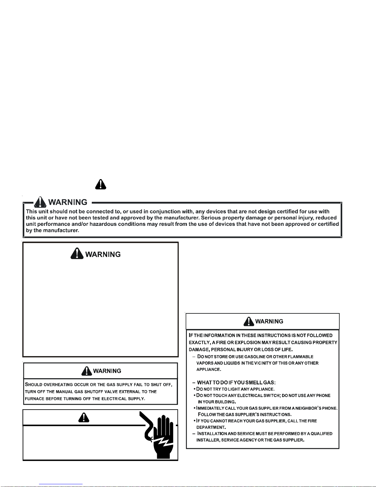
TABLE OF CONTENTS
IMPORTANT INFORMATION ...............................3
PRODUCT IDENTIFICATION ..............................5
FURNACE SPECIFICATIONS...............................9
OPERATION INSTRUCTIONS............................10
SYSTEM OPERATION. .....................................11
ACCESSORIES.................................................44
SERVICING TABLE OF CONTENTS..................48
SERVICING ........................................................49
MAINTENANCE ..................................................66
WIRING DIAGRAMS ....................................70 -72
IMPORTANT INFORMATION
Pride and workmanship go into every product to provide our customers with quality products. It is possible, however,
that during its lifetime a product may require service. Products should be serviced only by a qualified service technician
who is familiar with the safety procedures required in the repair and who is equipped with the proper tools, parts, testing
instruments and the appropriate service manual. REVIEW ALL SERVICE INFORMATION IN THE APPROPRIATE
SERVICE MANUAL BEFORE BEGINNING REPAIRS.
IMPORTANT NOTICES FOR CONSUMERS AND SERVICERS
RECOGNIZE SAFETY SYMBOLS, WORDS AND LABELS
O
NLY PERSONNEL THAT HAVE BEEN TRAINED TO INSTALL, ADJUST, SERVICE OR
REPAIR (HEREINAFTER
MANUAL SHOULD SERVICE THE EQUIPMENT
BE RESPONSIBLE FOR ANY INJURY OR PROPERTY DAMAGE ARISING FROM
IMPROPER SERVICE OR SERVICE PROCEDURES
ASSUME RESPONSIBILITY FOR ANY INJURY OR PROPERTY DAMAGE WHICH MAY
RESULT
. IN
LICENSES TO SERVICE THE EQUIPMENT SPECIFIED IN THIS MANUAL, ONLY
LICENSED PERSONNEL SHOULD SERVICE THE EQUIPMENT
INSTALLATION, ADJUSTMENT, SERVICING OR REPAIR OF THE EQUIPMENT
SPECIFIED IN THIS MANUAL, OR ATTEMPTING TO INSTALL, ADJUST, SERVICE OR
REPAIR THE EQUIPMENT SPECIFIED IN THIS MANUAL WITHOUT PROPER
TRAINING MAY RESULT IN PRODUCT DAMAGE, PROPERTY DAMAGE, PERSONAL
INJURY OR DEATH
, “
SERVICE
”)
THE EQUIPMENT SPECIFIED IN THIS
. THE
MANUFACTURER WILL NOT
. IF
YOU SERVICE THIS UNIT, YOU
ADDITION, IN JURISDICTIONS THAT REQUIRE ONE OR MORE
. I
MPROPER
.
WARNING
HIGH VOLTAGE
D
ISCONNECT ALL POWER BEFORE SERVICING OR
INSTALLI NG T HIS UNIT.
BE PRESENT .
DAMAGE, PE RSONAL INJUR Y OR DEATH.
FAILU RE TO DO SO MAY CAUSE P ROPERTY
MULTIPLE P OWER SOURCE S MAY
2
Page 3
IMPORTANT INFORMATION
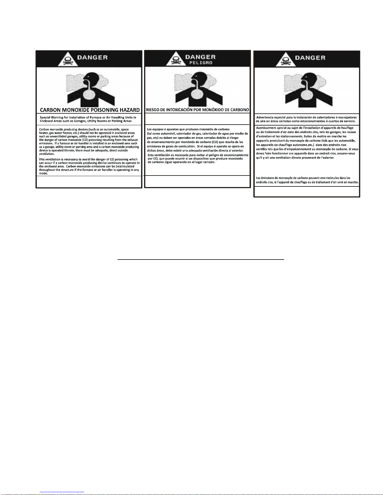
CO can cause serious illness inc luding permanent brain
damag e or death.
B10259-216
Advertencia especial para la instalación de calentadores ó manejadoras
de aire en áreas cerradas como estacionamientos ó cuartos de servicio.
Las emis iones de monóxido de carbono puede n circular a través
del apa rat o cuando se opera en c ualquier modo.
El monóx ido de carbono puede caus ar enfermedade s se veras
como daño cerebr al permanente ó muerte.
B10259-216
RISQUE D'EMPO ISONNEMENT AU
Cette ventilation est nécessaire pour éviter le danger d'intoxication
au CO pouvant survenir si un appareil produisant du monoxyde
de carb one continue de fonc tionner au sein de la zone confinée.
Le monoxyde de
des
carbone peut causer des maladies graves telles que
dommages permanents au cerveau et mem e la mort.
MONOXYDE DE CARBONE
B10259-216
To locate an authorized servicer, please consult your telephone book or the dealer from whom you purchased this
product. For further assistance, please contact:
CONSUMER INFORMATION LINE
GOODMAN® BRAND PRODUCTS
TOLL FREE
1-877-254-4729 (U.S. only)
email us at:
customerservice@goodmanmfg.com
fax us at: (731) 856-1821
(Not a technical assistance line for dealers.)
CONSUMER INFORMATION LINE
AMANA® BRAND PRODUCTS
TOLL FREE
1-877-254-4729 (U.S. only)
email us at:
hac.consumer.affairs@amanahvac.com
fax us at: (731) 856-1821
(Not a technical assistance line for dealers.)
Outside the U.S., call 1-713-861-2500.
(Not a technical assistance line for dealers.) Your telephone company will bill you for the call.
3
Page 4

IMPORTANT INFORMATION
A
A
A
A
D
G
N
I
RIVEE
R
U
GAS
I
N
ARRIVE
D
U
S
A
T
L
E
G
Z
A
MAN
A
L
U
G
A
L
E
N
I
E
T
L
E
G
A
Z
MANUA
E
L
R
V
E
O
I
N
N"
"
S
OW
V
"
R
M
"O
L
S
N
E
R
S
H
P
O
O
N
"
S
ARRIVE
O
B
I
T
N
E
A
Z
G
A
P
A
L
,
N
P
N
U
O
S
E
E
E
N
ARC
H
"
M
/
A
S
G
W
N
H
O
O
S
D
A
R
D
MAN
L
IN "
G
A
S
N
I
T
L
E
E
U
G
A
Z
G
A
S
E
I
T
N
L
V
E
E
R
I
G
U
Z
A
MANUA
LE
VER
I
N
N"
"
O
S
U
A
L
G
W
E
V
R
M
"O
N
R
E
H
S
O
O
S
P
O
N
"
A
N
B
I
T
O
A
N
N
L
G
H
S
P
O
Z
E
G
A
P
E
L
E
N
O
S
,
U
RCH
"
/
M
E
S
W
N
O
S
4
Page 5

PRODUCT IDENTIFICATION
The model and manufacturing number are used for positive identification of component parts used in manufacturing.
Please use these numbers when requesting service or parts information.
* M E C 96 60 3 B N A A
12345,67,8,91011121314
Brand Minor Revision
A - Amana
G - Goodman
Configuration Major Revision
M - U p flo w / Ho rizontal A - Initial Release
C - Down flow / Hori zontal B - 1st Revision
Motor NOx
V - V ariab l e Spee d ECM / ComfortNet N - Low NOx
E - M ulti-Speed ECM
S - Single Speed Cabinet Width
Gas Valve B - 17.5"
M - Modulating C - 21"
C - 2 Stage D - 24.5"
S - Single Stage
AFUE 2 - 800 CFM
96 - 96% AFUE 3 - 1200 CFM
92 - 92% AFUE 4 - 1600 CFM
MBTU/h
040 - 40,000 BTU/h
060 - 60,000 BTU/h
® Brand A - Initial Release
® Brand B - 1st Revision
A - 14"
Maximum CFM
5 - 2000 CFM
5
Page 6

PRODUCT IDENTIFICATION
MODEL # MFG. # DESCRIPTION
AMEC960402BNAA
AMEC96
GMEC96
AMEC960603BNAA
AMEC960803BNAA
AMEC961004CNAA
AMEC961205DNAA
AMEC960302BNAB
AMEC960402BNAB
AMEC960603BNAB
AMEC960803BNAB
AMEC961004CNAB
AMEC961205DNAB
AMEC960804CNAB
AMEC961005CNAB
AMEC960303ANAA
AMEC960403ANAA
AMEC960603ANAA
AMEC960302BNAC
AMEC960402BNAC
AMEC960603BNAC
AMEC960803BNAC
AMEC960804CNAC
AMEC961004CNAC
AMEC961005CNAC
AMEC961205DNAC
GMEC960402BNAA
GMEC960603BNAA
GMEC960803BNAA
GMEC961004CNAA
GMEC961205DNAA
GMEC960302BNAB
GMEC960402BNAB
GMEC960603BNAB
GMEC960803BNAB
GMEC961004CNAB
GMEC961205DNAB
GMEC960804CNAB
GMEC961005CNAB
GMEC960303ANAA
GMEC960403ANAA
GMEC960603ANAA
GMEC960302BNAC
GMEC960402BNAC
GMEC960603BNAC
GMEC960803BNAC
GMEC960804CNAC
GMEC961004CNAC
GMEC961005CNAC
GMEC961205DNAC
®
Ama na
flow/Horizontal Left and Right, 34.5" tall, Induced Draft, Nidec multi-speed ECMmotor.
Stainless Steel tubular heat exchanger. 115 volt silicon nitride igniter. Left or right gas.
Ama na
flow/Horizontal Left and Right, 34.5" tall, Induced Draft, Nidec multi-speed ECMmotor.
Stainless Steel tubular heat exchanger. 115 volt silicon nitride igniter. Left or right gas.
Ama na
flow/Horizontal Left and Right, 34.5" tall, Induced Draft, Nidec multi-speed ECMmotor.
Stainless Steel tubular heat exchanger. 115 volt silicon nitride igniter. Left or right gas.
Control board changed from PCBBF137 to PCBBF139. New control feature gives
installer multiple choices for constant fan mode.
Goodman
flow/Horizontal Left and Right, 34.5" tall, Induced Draft, Nidec multi-speed ECMmotor.
Stainless Steel tubular heat exchanger. 115 volt silicon nitride igniter. Left or right gas.
Goodman
flow/Horizontal Left and Right, 34.5" tall, Induced Draft, Nidec multi-speed ECMmotor.
Stainless Steel tubular heat exchanger. 115 volt silicon nitride igniter. Left or right gas.
For Control board part # change to PCBBF137 with heat speed DIP switches.
Goodman
flow/Horizontal Left and Right, 34.5" tall, Induced Draft, Nidec multi-speed ECMmotor.
Stainless Steel tubular heat exchanger. 115 volt silicon nitride igniter. Left or right gas.
For Control board part # change to PCBBF137 with heat speed DIP s witches. Control
board changed from PCBBF137 to PCBBF139. New control feature gives installer
multiple CFM choices for constant fan mode.
Brand 96% Two Stage Heating / Two Stage Cooling Gas Furnace, Up
®
Brand 96% Two Stage Heating / Two Stage Cooling Gas Furnace, Up
®
Brand 96% Two Stage Heating / Two Stage Cooling Gas Furnace, Up
®
Brand 96% Two Stage Heating / Two Stage Cooling Gas Furnace, Up
®
Brand 96% Two Stage Heating / Two Stage Cooling Gas Furnace, Up
®
Brand 96% Two Stage Heating / Two Stage Cooling Gas Furnace, Up
6
Page 7

PRODUCT IDENTIFICATION
MODEL # MFG. # DESCRIPTION
®
Brand 96% Two Stage Heating / Two Stage Cooling Gas Furnace, Counter
ACEC96
ACEC960403BNAA
ACEC960603BNAA
ACEC960803BNAA
ACEC961005BNAA
Amana
flow/Horizontal Left and Right, 34.5" tall, Induced Draft, Nidec multi-speed ECM motor.
Stainl ess Steel tubular heat exchanger. 115 volt silicon nitride igniter. Left or right gas.
PCBBF139 Control board which gives installer multiple CFM choices for constant fan
mode.
GCEC96
GCEC960403BNAA
GCEC960603BNAA
GCEC960803BNAA
GCEC961005BNAA
Goodman
flow/Horizontal Left and Right, 34.5" tall, Induced Draft, Nidec multi-speed ECMmotor.
Aluminized Steel tubular heat exchanger. 115 volt si licon nitride igniter. Left or right
gas. PCBBF139 Control board which gives installer multiple CFM choices for constant
fan mode.
®
Brand 96% Two Stage Heating / Two Stage Cooling Gas Furnace, Counter
7
Page 8

PRODUCT IDENTIFICATION
MODEL # M FG # DESCRI PT ION
AFE18-60A
AMU1620
AMU1625
AMU2020
AMU2025
GMU1620
GMU1625
GMU2020
GMU2025
ASAS-10
ASAS-11
ASAS-12
ASAS-18
DCVK-20 (CVE NT - 2)
DCVK-30 (CVE NT - 3)
0170K00000S
N/A
P1251305F
P1251306F
P1251307F
P1251308F
N/A
P1251301F
P1251302F
P1251303F
P1251304F
P1254001F
P1254002F
N/A
Foss il Fuel Kit.
above/downstream of a gas or f ossil fuel fur nac e when used with a heat pump. It will
operat e with single and two stage heat pumps and single and two stage furnaces
Med ia Air C leaner
efficiency air filtration device designed to remov e dir t, dust, pollen and other microscopic
part ic les fr om the air passing through it . Flexible performance range up t o 2,0
Electronic Air C leaner
cont aminants down to .01 microns. Carbon filters (optional) r emove odors. Dual indicator
lights show unit operat ion at a glance. E lec tronic proving switc h c ycle
Concentric Vent Kit
designed to allow ter minations of a dir ec t vent furnac e to be "c onc entrically" vented through
a wall or roof. T his kit allows a single penetrat ion to support ter min
Side Wall Only Concentric Vent Kit
to be used with 2" - 3" vent sy stems. The vent k it must terminate out side the str uc ture. This
kit is NOT intended f or use with single pipe (indirec t v ent) instal
The AF E 18- 60A c ontrol is designed for use where the indoor c oil is locat ed
. The A mana (AMU*) and G oodman (G MU*) Media Air Cleaner is a high
. The High-Ef ficiency Elec tronic Air Cleaner is designed to remov e air
. For use with Amana® Brand high efficiency f ur nac e models. This kit is
. For use with high efficiency f ur nac e models. This kit is
0170K00001S
EFR02
LPLP03
RF000142
CFSB17
CFSB21
CFSB24
N/A
P1221001
P1221002F
N/A
N/A
N/A
Side Wall Only Concentric Vent Kit
kit is to be used with 2" only vent systems. The vent kit must terminate outside the str uc ture.
This kit is NOT intended f or use with single pipe (indirec t v ent) in
External Filter Rack Kit
casing, f or installation of a permanent filter. The r ac k is mounted over the indoor air blower
compartment ar ea of either side panel, and pr ovide f ilter retentio
LP Gas Low Pressure Kit
80% and 90% single-stage and two- stage gas fired furnace pr oduc ts inst alled on LP gas
listed in this manual. This kit inc ludes harness adaptors to work with White-Rodgers sin
Vent Drain Coupling
the internal elbow is removed. May also be used in the combustion air intak e if
condensation is an issue.
Counterflow Subbase Kit
34.5 furnace model. T hese kit s are available for the following furnace widt h: 17.5" wide
(CF S B 17) , 21" wide (CFSB21, and 24" Wide CF S B 21. The k it must be used to pr event
excessive t emperat ur e from reaching combustible materials, if the fur nac e is installed on
combustible floor . This subbase effect ively separated the furnac e base and plenum from
combustile materials. T o ensure safe installation, do not install the counter flow floor base
directly on c ar peting, tile or other c ombusible mat er ial other t han wood flooring.
. This kit is intended to pr ovide a loc ation, ext er nal t o the fur nac e
. Designed for applic ation on Goodman® and Amana® Brand's
. For use when the fur nac es is installed in horizontal lef t position and
. For use with Amana® Brand, Goodman® brand 96% t wo stage
. For use with high efficiency 90% f ur nac e models. This
8
Page 9
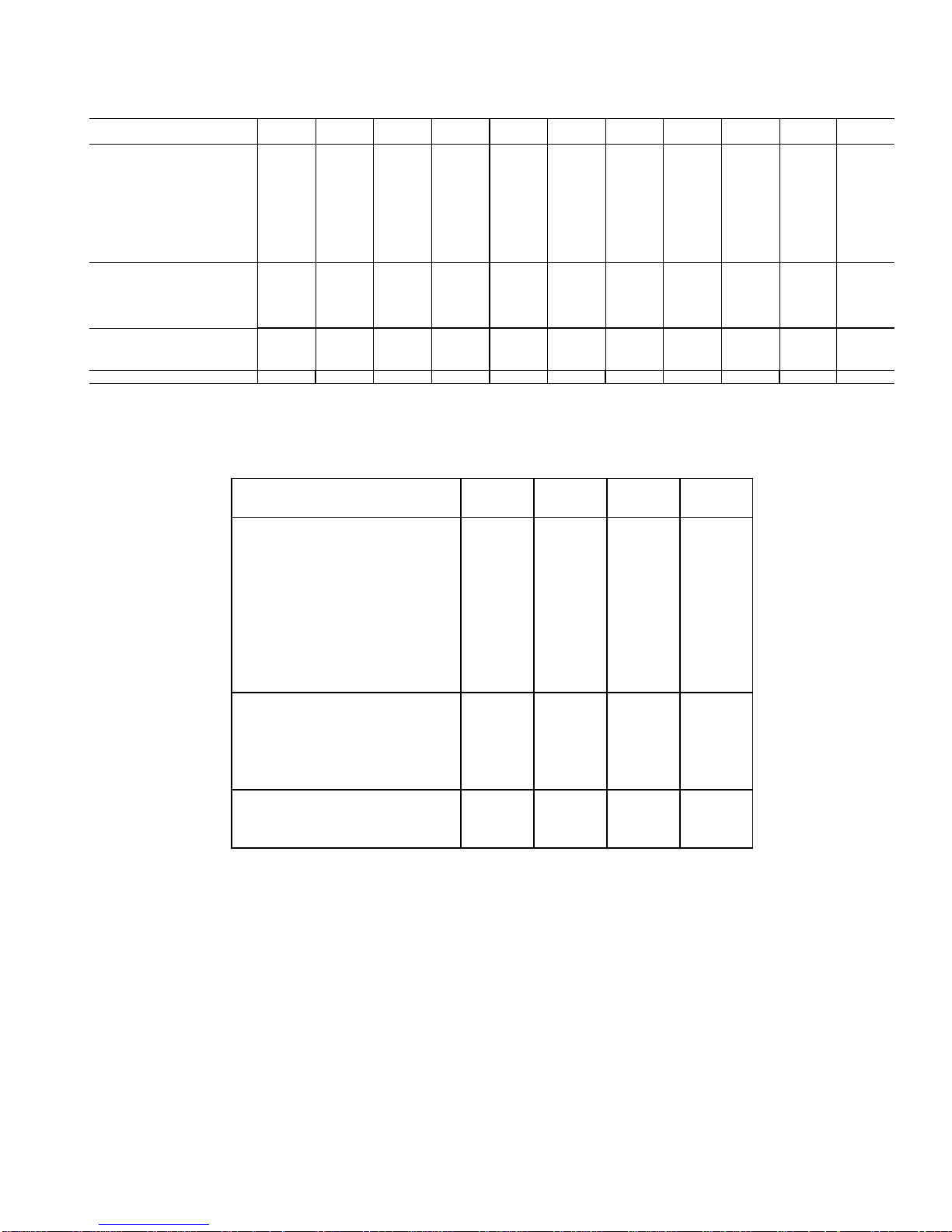
FURNACE SPECIFICATIONS
*MEC96
Heating Data
High Fire Input¹ 30,000 40,000 60,000 30,000 40,000 60,000 80,000 100,000 120,000 80,000 100,000
Hi gh Fi re Outp ut¹ 28,800 38,400 57,600 28,800 38,400 57,600 76,800 96,000 115,200 76,800 96,000
Low-Fire Steady-State Input¹ 21,000 28,000 42,000 21,000 28,000 42,000 56,000 70,000 84,000 56,000 70,000
Low -Fire Stea dy-Sta te Outp ut¹ 20,160 26,880 40,320 20,160 26,880 40,320 53,760 67,200 80,640 53,760 67,200
AFUE² 9696969696969696969696
Tem pera ture Ri se Ra nge (°F) 20 - 50 20 - 50 30 - 60 20 - 50 20 - 50 25 - 55 35 - 65 35 - 65 35 - 65 25 - 55 35 - 65
Ve nt Dia mete r³ 2" - 3" 2" - 3" 2" - 3" 2" - 3" 2" - 3" 2" - 3" 2" - 3" 2" - 3" 2" - 3" 2" - 3" 2" - 3"
No. of Burners 22322345645
Circul a t or Blower
Availa ble AC @ 0.5” ESP 1.5 - 3 1.5 - 3 1.5 - 3 1.5 - 2 1.5 - 3 1.5 - 3 1.5 - 3 1.5 - 4 3 - 5 2.5 - 4 3 - 5
Si ze (D x W) 11" x 6" 11" x 6" 11" x 6" 10" x 8" 10" x 8" 11" x 8" 11" x 8" 11" x 10" 11" x 11" 11" x 10" 11" x 10"
Ho rs epo wer @ 1075 RPM 1/2 1/2 1/2 1/2 1/2 1/ 2 1/2 1 1 3/4 1
Speed 55555555555
Electrical Data
Min. Circuit Ampacity
Max. Overcurrent Device (amps)
Shi ppi ng Weight (lbs)
4
0303ANA
5
8.6 8.6 8.6 8 8 8 8 13. 3 13.3 11.6 13.3
15 15 15 15 15 15 15 15 15 15 15
106 107 110 111 112 115 118 140 154 123 140
*MEC96
0403ANA
*MEC96
0603ANA
*MEC96
0302BNA
0403BN AA
*MEC96
0402BNA
*CEC96
*MEC96
0603BNA
*CEC96
0603BN AA
*MEC96
0803BNA
*CEC96
0803BN AA
*MEC96
1004CNA
*CEC96
1005CNA A
*MEC96
1205DNA
*MEC96
0804CNA
*MEC96
1005CNA
Heating Data
High F ire Input¹ 40,000 60,000 80,000 100,000
High Fi re Output¹ 38,400 57,600 76,800 96,000
Low-Fire Steady-State Input¹ 28,000 42,000 56,000 70,000
Low-Fi re Steady-State Output¹ 26,880 40,320 53,760 67,200
AFUE 96 96 96 96
Tempe rature Rise Range (°F) 25 - 55 25 - 55 40 - 70 36 - 65
Vent Diameterᶾ 2" - 3" 2" - 3" 2" - 3" 2" - 3"
No. of Burners 2345
Circula tor Blower
Available AC @ 0.5 ESP 1.5 - 3 1.5 - 3 1.5 - 3 3 - 5
Size (D x W) 10 x 8 10 x 8 11 x 8 11 x 10
Horsepow er @ 1075 RPM 1/2 1/2 1/2 1 HP
Speed 5555
Elec trical Data
Min. Circuit Ampacity⁴ 88813.3
Max. Overcurrent Device (AMPS)⁵ 15 15 15 15
1
Natural Gas BTU/h
2
DOE AFUE based upon Isolated Combustion System (ICS)
3
Installer must supply one or two PVC pipes: one for
combustion air (optional) and one for the flue outlet (required).
Vent pipe must be either 2" or 3" in diameter, depending upon
furnace input, number of elbows, length of run and installation
(1 or 2 pipes). The optional Combustion Air Pipe is dependent
on installation/code requirements and must be 2" or 3"
diameter PVC.
4
Minimum Circuit Ampacity = (1.25 x Circulator Blower Amps) +
ID Blower amps. Wire size should be determined in
accordance with National Electric Codes. Extensive wire runs
will require larger wire sizes.
5
Maximum Overcurrent Protection Device refers to maximum
recommended fuse or circuit breaker size. May use fuses or
HACR-type circuit breakers of the same size as noted
Notes
• All furnaces are manufactured for use on 115 VAC, 60 Hz,
single-phase electrical supply.
• Gas Service Connection 1/2" FPT
• Important: Size fuses and wires properly and make electrical
connections in accordance with the National Electrical Code
and/or all existing local codes.
• For bottom return: Failure to unfold flanges may reduce
airflow by up to 18%. This could result in performance and
noise issues.
• For servicing or cleaning, a 24" front clearance is required.
Unit connections (electrical, flue and drain) may necessitate
greater clearances than minimum clearances listed above. In
all cases, accessibility clearance must take precedence over
clearances from the enclosure where accessibility clearances
are greater.
9
Page 10
OPERA TIONS INSTRUCTIONS
Introduction
This is a Category lV furnace. This furnace uses a pressurized venting system and must be installed per National and
local codes requirements and the installation manual that
was shipped with the furnace.
The *MEC96 34.5" furnace is one of the products in our
newly redesigned line of shorter chassis furnaces. It is available in the following sizes and suitable for up flow / horizontal installation.
*MEC960303ANA *CEC960402BNAA
*MEC960403ANA *CEC960603BNAA
*MEC960603ANA *CEC960803BNAA
*MEC960302BNA *CEC961005CNAA
*MEC960402BNA Suitable for counter
*MEC960603BNA flow or horizontal
*MEC960803BNA installation.
*MEC960804CNA
*MEC961004CNA
*MEC961005CNA
*MEC961205DNA
Safety
Please adhere to the following warnings and cautions when
installing, adjusting, altering, servicing, or operating the furnace.
WARNING
T
O PREVENT PERSONAL INJURY OR DEATH DUE TO IMPROPER INSTALLATION,
ADJUSTMENT, ALTERATI ON, SERV ICE OR MAINTENANCE, R EFER TO THI S
MANUAL.
QUALIFIED INSTALLE R, SERVICE AGENCY OR THE GAS SUPPLIER.
T
MAY CAUSE SERI OUS ILLNESS OR DEATH AN D WHICH ARE KNOWN TO TH E
S
REPRODUCTIVE HARM.
TO PREVENT POSSIBLE PROPERTY DAMAGE, PERSONAL INJURY OR DEATH
DUE TO ELECTRICAL SHOCK, THE FURNACE MUST BE LOCATED TO PROTECT
THE ELEC TRICA L COMPON ENTS FROM WAT ER.
OR ADDITIONAL ASSISTANCE OR INFORMATION, CONSULT A
F
WARNING
HIS PRODUCT CONTAINS OR PRODUCES A CHEMICAL OR CHEMICALS WHICH
TATE OF CALIFORNIA TO CAUSE CANCER, BI RTH DEFECTS OR OTHER
WARNING
age. By putting the furnace, the control, and the person at
the same electrostatic potential, these steps will help avoid
exposing the integrated control module to electrostatic discharge. This procedure is applicable to both installed and
uninstalled (ungrounded) furnaces.
1. Disconnect all power to the furnace. Do not touch the
integrated control module or any wire connected to the
control prior to discharging your body’s electrostatic
charge to ground.
2. Firmly touch a clean, unpainted, metal surface of the
furnace near the control. Any tools held in a person’s
hand during grounding will be discharged.
3. Service integrated control module or connecting wiring
following the discharge process in Step 2. Use caution
not to recharge your body with static electricity; (i.e., do
not move or shuffle your feet, do not touch ungrounded
objects, etc.). If you come in contact with an ungrounded
object, repeat Step 2 before touching control or wires.
4. Discharge any static electricity from your body to ground
before removing a new control from its container. Follow
Steps 1 through 3 if installing the control on a furnace.
Return any old or new controls to their containers before
touching any ungrounded object.
Product Application
This product is designed for use as a residential home gas
furnace. It is not designed or certified for use in mobile home,
trailer, or recreational vehicle applications.
This furnace can be used in the following non-industrial
commercial applications: Schools, Office buildings, Churches,
Retail stores, Nursing homes, Hotels/motels, Common or
office areas. In such applications, the furnace must be installed
with the
installation instructions.
The *MEC96 furnaces are ETL certified appliances and are
appropriate for use with natural or propane gas. (NOTE: If
using propane gas, a propane conversion kit is required).
*MEC96 furnaces are dual certified.
Dual certification means that the combustion air inlet pipe is
optional and the furnace can be vented as a:
Non-direct vent (single pipe) central forced air furnace
in which combustion air is taken from the installation
area or from air ducted from the outside or,
Direct vent (dual pipe) central forced air furnace in which
all combustion air supplied directly to the furnace burners through a special air intake system outlined in
this manual and the installation instructions.
To ensure proper installation, operation and servicing, thoroughly read the installation and service manuals for specifics pertaining to the installation, servicing and application of
this product.
Charge (ESD) Precautions
NOTE: Discharge body’s static electricity before touching
unit. An electrostatic discharge can adversely affect electrical components.
Use the following precautions during furnace installation and
servicing to protect the integrated control module from dam-
10
WARNING
OSSIBLE PROPERTY D AMAGE, PERSONAL INJ URY OR DEATH DUE TO FIRE,
P
EXPLOSION, SMOKE, S OOT, CONDENSTAION, E LECTRICAL SHOCK OR C ARBON
MONOXIDE MAY RESULT FROM IMPROPER INSTALLATION, RE PAIR, OPERATI ON,
OR MAINTENANCE OF THI S PRODUCT.
Page 11
SYSTEM OPERATION
WARNING
T
O PREVENT PROPERTY DAMAGE, PERSONAL INJ URY OR DEATH D UE TO FIRE,
DO NOT INSTALL T HIS FURNACE IN A MOBILE HOME, TRAILER, OR RECREATIONAL
VEHICLE.
To ensure proper furnace operation, install, operate, maintain and service the furnace in accordance with the installation, operation and service instructions, all local building
codes and ordinances. In their absence, follow the latest
edition of the National Fuel Gas Code (NFPA 54/ANSI
Z223.1), and/or CAN/CGA B149 Installation Codes, local
plumbing or waste water codes, and other applicable codes.
A copy of the National Fuel Gas Code (NFPA 54/ANSI
Z223.1) can be obtained from any of the following:
American National Standards Institute
25 West 43rd Street, 4th Floor
New York, NY 10036
National Fire Protection Association
1 Batterymarch Park
Quincy, MA 02169-7471
CSA International
8501 East Pleasant Valley
Cleveland, OH 44131
A copy of the CAN/CGA B149 Installation Codes can be
obtained from:
CSA International
178 Rexdale Boulevard
Etobicoke, Ontario, Canada M9W, 1R3
The rated heating capacity of the furnace should be greater
than or equal to the total heat loss of the area to be heated.
The total heat loss should be calculated by an approved
method or in accordance with “ASHRAE Guide” or “Manual
J-Load Calculations” published by the Air Conditioning Contractors of America.
Location Requirements and Considerations
WARNING
O PREVENT POSSIBLE EQUI PMENT DAMAGE, PROPERTY DAMAGE, PERSONAL
T
INJURY OR DEATH, THE FO LLOWING BULLET P OINTS MUST BE OBSERVED
WHEN INSTALLING THE UNIT.
Follow the instructions listed below when selecting a furnace location. Refer also to the guidelines provided in the
Combustion and Ventilation Air Requirements section in
this manual or the installation instructions for details.
• Centrally locate the furnace with respect to the proposed or existing air distribution system.
• Ensure the temperature of the return air entering the
furnace is between 55°F and 100°F when the furnace
is heating.
• If the furnace is installed in an application where the
typical operating sound level of a furnace is deemed
objectionable, an optional sound reduction kit is available. Consult your local distributor for more details.
• Provide provisions for venting combustion products
outdoors through a proper venting system. Special
consideration should be given to vent/flue pipe routing
and combustion air intake pipe when applicable.
90% Furnaces: Refer to the Vent/Flue Pipe and Com-
bustion Air Pipe -Termination Locations section in this
manual or the installation instructions for appropriate
termination locations. Also for 90% furnaces, refer to
the Vent/Flue Pipe and Combustion Air Pipe -Termi-
nation Locations section in this manual or the installation instructions to determine if the piping system
from furnace to termination can be accomplished
within the guidelines given.
NOTE: The length of flue and/or combustion air piping can
be a limiting factor in the location of the furnace.
• Locate the 90% furnace so that the condensate can
be piped at a downward slope away from the furnace
to the drain. Do not locate the furnace or its condensate drainage system in any area subject to below
freezing temperatures without proper freeze protection. Refer to the Condensate Drain Lines and Trap
section in this manual or the installation instructions
for further details.
• Set the 90% furnace on a level floor to enable proper
condensate drainage. If the floor becomes wet or damp
at times, place the furnace above the floor on a
concrete base sized approximately 1-1/2" larger than
the base of the furnace. Refer to the Horizontal Appli-
cations and Considerations section in this manual or
the installation instructions for leveling of horizontal
furnaces.
• Ensure upflow or horizontal furnaces are not installed
directly on carpeting, or any other combustible material. The only combustible material allowed is wood.
• Exposure to contaminated combustion air will result
in safety and performance-related problems. Do not
install the furnace where the combustion air is exposed to the following substances:
chlorinated waxes or cleaners
chlorine-based swimming pool chemicals
water softening chemicals
deicing salts or chemicals
carbon tetrachloride
halogen type refrigerants
cleaning solutions (such as perchloroethylene)
printing inks
paint removers
varnishes
11
Page 12
SYSTEM OPERATION
hydrochloric acid
cements and glues
antistatic fabric softeners for clothes dryers
and masonry acid washing materials
• Isolate a non-direct vent furnace if it is installed near
an area frequently contaminated by any of the above
substances. This protects the non-direct vent furnace
from airborne contaminants. To ensure that the enclosed non-direct vent furnace has an adequate sup-
ply of combustion air, vent from a nearby uncontaminated room or from outdoors. Refer to the Combus-
tion and Ventilation Air Requirements section in this
manual or the installation instructions for details.
• If the furnace is used in connection with a cooling
unit, install the furnace upstream or in parallel with
the cooling unit coil. Premature heat exchanger failure will result if the cooling unit coil is placed in the
return air of the furnace.
• If the furnace is installed in a residential garage, position the furnace so that the burners and ignition
source are located not less than 18 inches (457 mm)
above the floor. Protect the furnace from physical damage by vehicles.
• If the furnace is installed horizontally, the furnace access doors must be vertical so that the burners fire
horizontally into the heat exchanger. Do not install
the unit with the access doors on the “up/top” or “down/
bottom” side of the furnace.
• On counterflow installations, the air conditioning coil
must be downstream on the supply (positive) side of
the furnace heat exchanger.
• Counterflow Installation over a noncombustible floor.
Before setting the furnace over the plenum opening,
ensure the surface around the opening is smooth and
level. A tight seal should be made between the furnace base and floor by using a silicone rubber caulking compound or cement grout.
• Counterflow Installation over a combustible floor. If
installation over a combustible floor becomes necessary, use an accessory sub-base (see Specification
Sheet applicable for your model for details). A special accessory sub-base must be used for upright
counterflow unit installations over any combustible
material including wood. Refer to sub-base instructions for installation details. Follow the instructions
with the sub-base for proper installation. Do not install the furnace directly on carpeting, tile, or other
combustible material other than wood flooring.
(NOTE: The sub-base will not be required if an air
conditioning coil is installed between the supply air
opening on the furnace and the floor.)
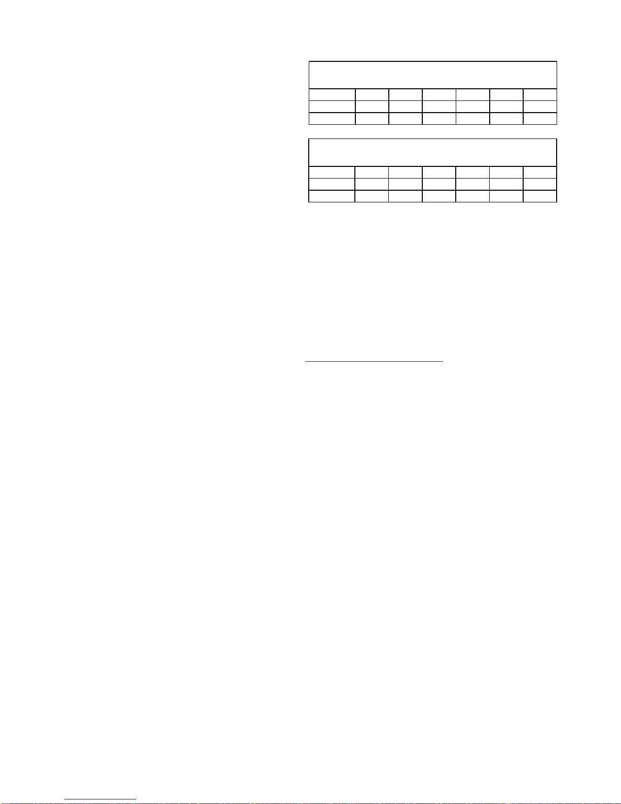
*MEC96 M INIMUM CLEA RANCES TO COM BUSTIBLE MATERIALS
POSITION* SIDES REAR FRONT BOTTOM FLUE TOP
Upflow 0" 0" 1" C 0" 1"
Horiz ontal 6" 0" 1" C 0" 6"
*CEC9 6 MINIM UM CLE ARANCE S TO CO MBUSTIB LE MATER IA LS
POSITION* SIDES REAR FRONT BOTTOM FLUE TOP
Counterflow0"0"1"NC0"
Horizontal 6" 0" 1" C 0" 6"
• C = If placed on combustible floor, floor MUST be wood only.
• NC = For installation on non-combustible floors only. A combustible
subbase must be used for installations on combustible flooring.
• For servicing or cleaning, a 24" front clearance is recommended.
• Unit connections (electrical, flue, and drain) may necessitate greater
clearances than the minimum clearances listed above.
• In all cases, accessibility clearance must take precedence over from
the enclosure where accessibility clearances are greater.
• Approved for line contact in the horizontal position.
Clearances and Accessibility
Installations must adhere to the clearances to combustible
materials to which this furnace has been design certified.
The minimum clearance information for this furnace is provided on the unit’s clearance label. These clearances must
be permanently maintained. Refer to Specification Sheet for
minimum clearances to combustible materials. Clearances
must also accommodate an installation’s gas, electrical,
and drain trap and drain line connections. If the alternate
combustion air intake or vent/flue connections are used on
a 90% furnace, additional clearances must be provided to
accommodate these connections. Refer to Vent Flue Pipe
and Combustion Air Pipe section in this manual or the installation instructions for details. NOTE: In addition to the
required clearances to combustible materials, a minimum
of 24 inches service clearance must be available in front of
the unit.
A furnace installed in a confined space (i.e., a closet or
utility room) must have two ventilation openings with a total
minimum free area of 0.25 square inches per 1,000 BTU/hr
of furnace input rating. One of the ventilation openings must
be within 12 inches of the top; the other opening must be
within 12 inches of the bottom of the confined space. In a
typical construction, the clearance between the door and
door frame is usually adequate to satisfy this ventilation
requirement.
12
Page 13
SYSTEM OPERATION
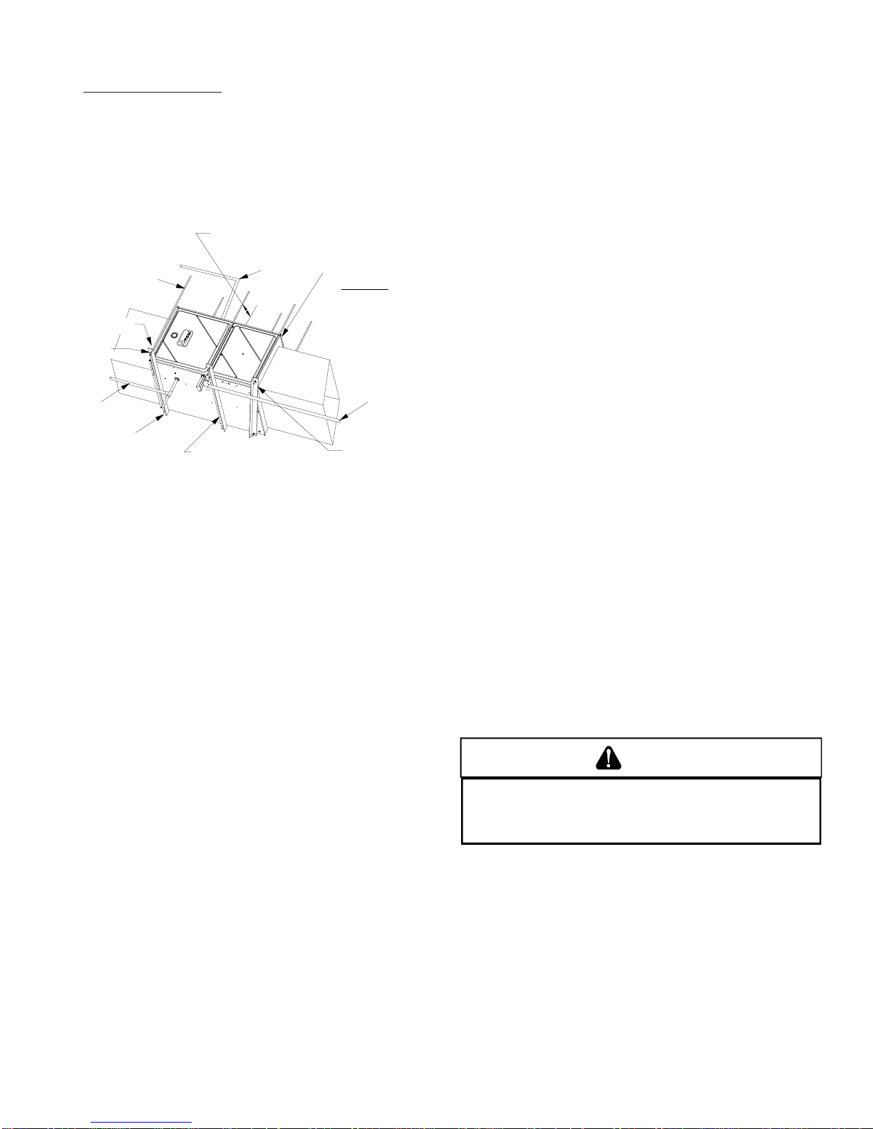
Furnace Suspension
If suspending the furnace from rafters or joist, use 3/8"
threaded rod and 2”x2”x1/8” angle iron as shown in the following figure. If the furnace is installed in a crawl space it
must also be suspended from the floor joist or supported by
a concrete pad. Never install the furnace on the ground or
allow it to be exposed to water. The length of rod will depend on the application and the clearances necessary.
PROVIDE 8" MINIMUM CLEARANCE BETWEEN
CENTER ROD AND FURNACE CABINET
TO ALLOW FOR CIRCULATOR BLOWER REMOVAL.
3/8" DIAMETER
THREADED ROD
(6 PLACES)
HOLD DOWN
NUTS
SUPPORT
NUTS
GAS PIPING
2"X2"X1/8" ANGLE IRON
(3 PLACES)
ALTERNATE
GAS PIPING
POSITION AS CLOSE AS POSSIBLE
TO BLOWER DECK TO ALLOW FOR
CIRCULATOR BLOWER REMOVAL.
ASSURE FURNACE IS LEVEL FROM
END TO END.
ON
90% FURNACES MAKE SURE
THE UNIT HAS A SLIGHT
FORWARD TILT WITH THE FRONT
OF THE FURNACE 0"-3/4"
BELOW THE BACK OF THE FURNACE.
CONDENSATE
DRAIN
TILT OUTWARD TO ALLOW FOR
DOOR AND CIRCULATOR BLOWER
REMOVAL.
90% Suspended Furnace Shown
EXISTING FURNACE REMOVAL
NOTE: When an existing furnace is removed from a venting
system serving other appliances, the venting system may
be too large to properly vent the remaining attached appliances.
The following vent testing procedure is reproduced from the
American National Standard/National Standard of Canada for
Gas-Fired Central Furnaces ANSI Z21.47, latest edition,
CSA-2.3b, latest edition Section 1.23.1.
The following steps shall be followed with each appliance connected to
the venting system placed in operation, while any other appliances
connected to the venting system are not in operation:
a. Seal any unused openings in the venting system;
b. Inspect the venting system for proper size and horizontal pitch,
as required by the National Fuel Gas Code, ANSI Z223.1 or the
CSA B149 Installation Codes and these instructions. Determine
that there is no blockage or restriction, leakage, corrosion and
other deficiencies which could cause an unsafe condition;
c. In so far as practical, close all building doors and windows and
all doors between the space in which the appliance(s) connected
to the venting system are located and other spaces of the building.
Turn on clothes dryers and any appliance not connected to the
venting system. Turn on any exhaust fans, such as range hoods
and
bathroom exhausts, so they shall operate at maximum speed.
Do not operate a summer exhaust fan. Close fireplace dampers;
d. Follow the lighting instructions. Place the appliance being in-
spected in operation. Adjust thermostat so appliance shall
operate continuously;
e. Test for draft hood equipped spillage at the draft hood relief
opening after 5 minutes of main burner operation. Use the flame
of a match or candle;
f. After it has been determined that each appliance connected to the
venting system properly vents when tested as outlined above,
return doors, windows, exhaust fans, fireplace dampers and any
other gas burning appliance to their previous conditions of use;
g . If improper venting is observed during any of the above tests, the
common venting system must be corrected.
Corrections must be in accordance with the latest edition of
the National Fuel Gas Code NFPA 54/ANSI Z223.1 and/or
CSA B149 Installation Codes.
If resizing is required on any portion of the venting system,
use the appropriate table in Appendix G in the latest edition
of the National Fuel Gas Code ANSI Z223.1 and/or CSA B149
Installation Codes.
Thermostat Requirements
A two stage heat/cool thermostat is recommended. A single
stage heating thermostat may be used. It is recommended
that a high quality thermostat with a "C" terminal is used to
operate the furnace.
Thermostat Location
In an area having good air circulation, locate the thermostat
about five feet high on a vibration-free inside wall. Do not
install the thermostat where it may be influenced by any of
the following:
• Drafts, or dead spots behind doors, in corners, or under cabinets.
• Hot or cold air from registers.
• Radiant heat from the sun.
• Light fixtures or other appliances.
• Radiant heat from a fireplace.
• Concealed hot or cold water pipes, or chimneys.
• Unconditioned areas behind the thermostat and dehumidistat, such as an outside wall.
COMBUSTION AND VENTILATION AIR
REQUIREMENTS
WARNING
OSSIBLE PROPERTY DAMAGE, PERSONAL I NJURY OR DEATH MAY OCCUR
P
IF THE FURNACE I S NOT PR OVIDED WITH ENOUGH FRESH AIR FOR PROPER
COMBUSTION AND VENTIL ATION OF F LUE GASES. MOST HOMES REQUI RE
OUTSIDE AIR BE SUPPLIED TO THE FURNACE AREA.
Improved construction and additional insulation in buildings
have reduced heat loss by reducing air infiltration and escape around doors and windows. These changes have helped
in reducing heating/cooling costs but have created a problem supplying combustion and ventilation air for gas fired
and other fuel burning appliances. Appliances that pull air
out of the house (clothes dryers, exhaust fans, fireplaces,
etc.) increase the problem by starving appliances for air.
When the furnace is installed as a direct ven (2-pipe) furnace, no special provisions for air for combustion are required. However, if this furnace is to be installed in the same
space with other gas appliances, such as a water heater,
13
Page 14

SYSTEM OPERATION
ensure there is an adequate supply of combustion and ventilation air for the other appliances. Refer to the latest edition of the National Fuel Gas Code NFPA 54/ANSI Z223.1
(Section 9.3), or CAN/CGA B149 Installation Codes (Sections 7.2, 7.3, or 7.4), or applicable provisions of the local
building codes for determining the combustion air requirements for the appliances.
Most homes will require outside air be supplied to the furnace area by means of ventilation grilles or ducts connecting directly to the outdoors or spaces open to the outdoors
such as attics or crawl spaces.
The following information on air for combustion and ventilation
is reproduced from the National Fuel Gas Code NFPA 54/ANSI
Z223.1 Section 9.3.
9.3* Air for Combustion and Ventilation.
9.3.1 General.
9.3.1.1 Air for combustion, ventilation, and dilution of flue gases for
appliances installed in buildings shall be obtained by application of one
of the methods covered in 9.3.2 through 9.3.6. Where the requirements
of 9.3.2 are not met, outdoor air shall be introduced in accordance with
methods covered in 9.3.3 through 9.3.6.
Exception No. 1: This provision shall not apply to direct vent appliances.
9.3.1.2 Appliances of other than natural draft design and other than
Category 1 vented appliances shall be provided with combustion, ventilation, and dilution air in accordance with the appliance manufacturer’s
instructions.
9.3.1.3 Appliances shall be located so as not to interfere with proper
circulation of combustion, ventilation, and dilution air.
9.3.1.4 Where used, a draft hood or a barometric draft regulator shall be
installed in the same room or enclosure as the appliance served so as to
prevent any difference in pressure between the hood or regulator and the
combustion air supply.
(1) For appliances other than fan-assisted, calculate using the follow-
ing equation:
Required Volume
(2) For fan-assisted appliances, calculate using the following equation:
Required Volume
where:
I
I
ACH = air change per hour (percent of volume of space exchanged
(3) For purposes of this calculation, an infiltration rate greater than
9.3.2.3 Indoor Opening Size and Location. Openings used to connect indoor spaces shall be sized and located in accordance with the
following:
(1)*Combining spaces on the same story. Each opening shall have a
NOTE: Each opening must have
a free area of not less than one
square inch per 1000 BTU of
the total input rating of all equipment in the enclosure, but not
less than 100 square inches.
= all appliances other than fan-assisted input in Btu per
other
fan
0.60 ACH shall not be used in the equations in 9.3.2.2(1) and
9.3.2.2(2).
minimum free area of 1 in.2/1000Btu/hr (2200 mm2/kW) of the total
input rating of all appliances in the space but not less than 100 in.
(0.60m2). One opening shall commence within 12 in. (300 mm) of
the top, and one opening shall commence within 12 in. (300 mm) of
the bottom, of the enclosure [see Figure A.9.3.2.3(1)]. The minimum dimension of air openings shall be not less than 3 in. (80 mm).
hour
= fan-assisted appliances input in Btu per hour
per hour, expressed as a decimal)
> ________ _________
other
> ________ _________
fan
3
21 ft
ACH 1000 Btu/hr
3
15 ft
ACH 1000 Btu/hr
Chimney or Gas Vent
I
other
(
I
fan
(
)
)
2
9.3.1.5 Makeup air requirements for the operation of exhaust fans, kitchen
ventilation systems, clothes dryers, and fireplaces shall be considered in
determining the adequacy of a space to provide combustion air requirements.
9.3.2 Indoor Combustion Air. The required volume of indoor air shall
be determined in accordance with the method in 9.3.2.1 or 9.3.2.2 except that where the air infiltration rate is known to be less than 0.40
ACH, the method in 9.3.2.2 shall be used. The total required volume
shall be the sum of the required volume calculated for all appliances
located within the space. Rooms communicating directly with the space
in which the appliances are installed through openings not furnished
with doors, and through combustion air openings sized and located in
accordance with 9.3.2.3, are considered a part of the required volume.
9.3.2.1* Standard Method. The minimum required volume shall be 50
ft 3 per 1,000/Btu/hour (4.8m3/kW).
9.3.2.2* Known Air Infiltration Rate Method. Where the air infiltration rate of a structure is known, the minimum required volume shall be
determined as follows:
14
Opening
Water
Heater
Furnace
Opening
Figure A.9.2.3.3.(1) All Combustion Air from Adjacent
Indoor Spaces through Indoor Combustion Air Openings.
(2) Combining spaces in different stories. The volumes of spaces in
different stories shall be considered as communicating spaces where
such spaces are connected by one or more openings in doors or
floors having a total minimum free area of 2 in.2/1000 Btu/hr (4400
mm2/kW) of total input rating of all appliances.
9.3.3 Outdoor Combustion Air. Outdoor combustion air shall be
provided through opening(s) to the outdoors in accordance with the
methods in 9.3.3.1 or 9.3.3.2. The minimum dimension of air openings
shall not be less than 3 in. (80 mm).
Page 15
SYSTEM OPERATION
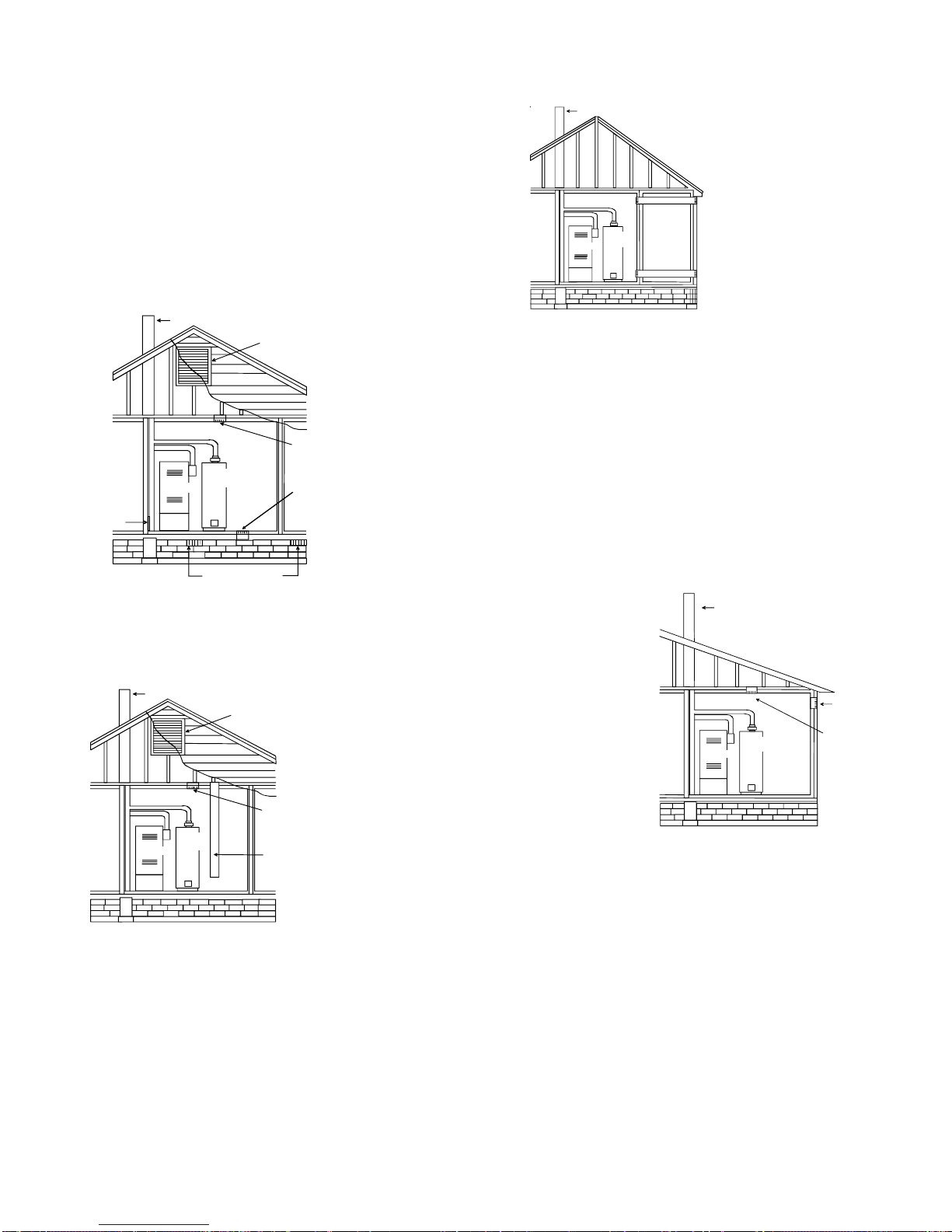
A
9.3.3.1 Two Permanent Openings Method. Two permanent openings, one commencing within 12 in. (300 mm) of the top and one commencing within 12 in. (300 mm) of the bottom, of the enclosure shall be
provided. The openings shall communicate directly, or by ducts, with
the outdoors or spaces that freely communicate with the outdoors, as
follows:
(1)*Where directly communicating with the outdoors or where commu-
nicating to the outdoors through vertical ducts, each opening shall
have a minimum free area of 1 in.
total input rating of all appliances in the enclosure. [See Figure
A.9.3.3.1(1)(a) and Figure A.9.3.3.1(1)(b).]
Chimney or Gas Vent
Water
Heater
Furnace
lternate
air inlet
Ventilation louvers for
unheated crawl space
Figure A.9.3.3.1(1)(a) All Combustion Air Fr om Outdoors -
Inlet Air from Ventilated Crawl Space and Outlet Air
to Ventilated Attic.
2
/4000 Btu/hr (550 min2/kW) of
Ventilation louvers
(each end of attic)
NOTE: The inlet and outlet a ir
openings must each have a free
area of not less than one square
inch per 4000 BTU of the
total input rating of all equipment
in the enclosure.
Outlet Air
Inlet Air
Chimney or Gas Vent
NOTE: The ai r du ct openings
must have a free area of not
less than one squ are inch per
2000 BTU of the total input
rating of all equipment in the
enclosure*.
Furnace
Water
Heater
Outlet air duct
Inlet air duct
Figure A.9.3.3.1(2) All Combustion Air From Outdoors
through Horizontal Ducts.
9.3.3.2* One Permanent Opening Method. One permanent open-
ings, commencing within 12 in. (300 mm) of the top of the enclosure,
shall be provided. The appliance shall have clearances of at least 1 in.
(25 mm) from the sides and back and 6 in. (150 mm) from the front of
the appliance. The opening shall directly communicate with the outdoors or shall communicate through a vertical or horizontal duct to the
outdoors or spaces that freely communicate with the outdoors (see
Figure A.9.3.3.2) and shall have a minimum free area of the following:
(1) 1 in.
2
/3000 Btu/hr (700 mm2 per kW) of the total input rating of all
appliances located in the enclosure, and
(2) Not less than the sum of the areas of all vent connectors in the
space.
NOTE: The single opening must have
a free area of not less than one
square inch per 3000 BTU of
the total input rating of all equipment in the enclosure, but not less than
the sum of the areas of all vent
connectors in the confin ed spa ce.
Chimney or Gas Vent
Chimney or Gas Vent
Ventilation louvers
(each end of attic)
NOTE: The inlet and outlet air
openings must each have a free
area of not less than one square
inch per 4000 BTU of the
total input rating of all equipmen t
in the enclosure.
Outlet Air
Water
Heater
Furnace
Inlet air duct
[ends 1 ft (300 mm)
above floor]
Figure A.9.3.3.1(1)(b) All Combustion Air
From Outdoors through Ventilated Attic.
(2)*Where communicating with the outdoors through horizontal ducts,
each opening shall have a minimum free area of 1 in.2/2000 Btu/hr
(1100 min2/kW) of total input rating of all appliances in the enclosure. [See Figure A.9.3.3.1(2).]
Opening
Alternate
Opening
Location
Furnace
Water
Heater
Figure A.9.3.3.2 All Combustion Air
From Outdoors through Single Combustion Air Opening.
9.3.4 Combination Indoor and Outdoor Combustion Air. The use
of a combination of indoor and outdoor combustion air shall be in
accordance with (1) through (3) (see example calculation in Annex J]:
(1) Indoor Openings: Where used, openings connecting the interior
spaces shall comply with 9.3.2.3.
(2) Outdoor Opening(s) Location. Outdoor opening(s) shall be lo-
cated in accordance with 9.3.3.
(3) Outdoor Opening(s) Size. The outdoor opening(s) size shall be
calculated in accordance with the following:
(a) The ratio of the interior spaces shall be the available volume
of all communicating spaces divided by the required volume.
(b) The outdoor size reduction factor shall be 1 minus the ratio
of interior spaces.
15
Page 16

SYSTEM OPERATION
(c) The minimum size of outdoor opening(s) shall be the full size
of outdoor opening(s) calculated in accordance with 9.3.3,
multiplied by the reduction factor. The minimum dimension
of air openings shall not be less than 3 in. (80 mm).
9.3.8.4 Ducts shall not serve both upper and lower combustion air
openings where both such openings are used. The separation between
ducts servicing upper and lower combustion air openings shall be maintained to the source of combustion air.
9.3.5 Engineered Installations. Engineered combustion air installations shall provide an adequate supply of combustion, ventilation, and
dilution air and shall be approved by the authority having jurisdiction.
9.3.6 Mechanical Combustion Air Supply . Where all combustion air
is provided by a mechanical air supply system, the combustion air shall
be supplied form outdoors at the minimum rate of 0.35 ft3/min per
1000 Btu/hr (0.034 m3/min per kW) for all appliances located within
the space.
9.3.6.1 Where exhaust fans are installed, additional air shall be provided
to replace the exhausted air.
9.3.6.2 Each of the appliances served shall be interlocked to the mechanical air supply system to prevent main burner operation where the
mechanical air supply system is not in operation.
9.3.6.3 Where combustion air is provided by the building’ s mechanical
ventilation system, the system shall provide the specified combustion
air rate in addition to the required ventilation air.
9.3.7 Louvers, Grilles, and Screens.
9.3.7.1 Louvers and Grilles. The required size of openings for com-
bustion, ventilation, and dilution air shall be based on the net free area
of each opening. Where the free area through a design of louver or grille
or screen is known, it shall be used in calculating the size opening
required to provide the free area specified. Where the louver and grille
design and free area are not known, it shall be assumed that wood
louvers will have 25 percent free area, and metal louvers and grilles will
have 75 percent free area. Nonmotorized louvers and grilles shall be
fixed in the open position.
9.3.7.2 Minimum Scree Mesh Size. Screens shall not be smaller than
1/4 in. mesh.
9.3.7.3 Motorized Louvers. Motorized louvers shall be interlocked
with the appliance so they are proven in the full open position prior to
main burner ignition and during main burner operation. Means shall be
provided to prevent the main burner form igniting should the louver fail
to open during burner startup and to shut down the main burner if the
louvers close during burner operation.
9.3.8 Combustion Air Ducts. Combustion air ducts shall comply with
9.3.8.1 through 9.3.8.8.
9.3.8.1 Ducts shall be constructed of galvanized steel or a material
having equivalent corrosion resistance, strength, and rigidity.
Exception: Within dwellings units, unobstructed stud and joist spaces
shall not be prohibited from conveying combustion air, provided that
not more than one fireblock is removed.
9.3.8.2 Ducts shall terminate in an unobstructed space, allowing free
movement of combustion air to the appliances.
9.3.8.5 Ducts shall not be screened where terminating in an attic space.
9.3.8.6 Horizontal upper combustion air ducts shall not slope down-
ward toward the source of combustion air.
9.3.8.7 The remaining space surrounding a chimney liner, gas vent,
special gas vent, or plastic piping installed within a masonry, metal, or
factory built chimney shall not be used to supply combustion air.
Exception: Direct vent appliances designed for installation in a solid
fuel-burning fireplace where installed in accordance with the
manufacture’s installation instructions.
9.3.8.8 Combustion air intake openings located on the exterior of the
building shall have the lowest side of the combustion air intake openings located at least 12 in. (300 mm) vertically from the adjoining grade
level.
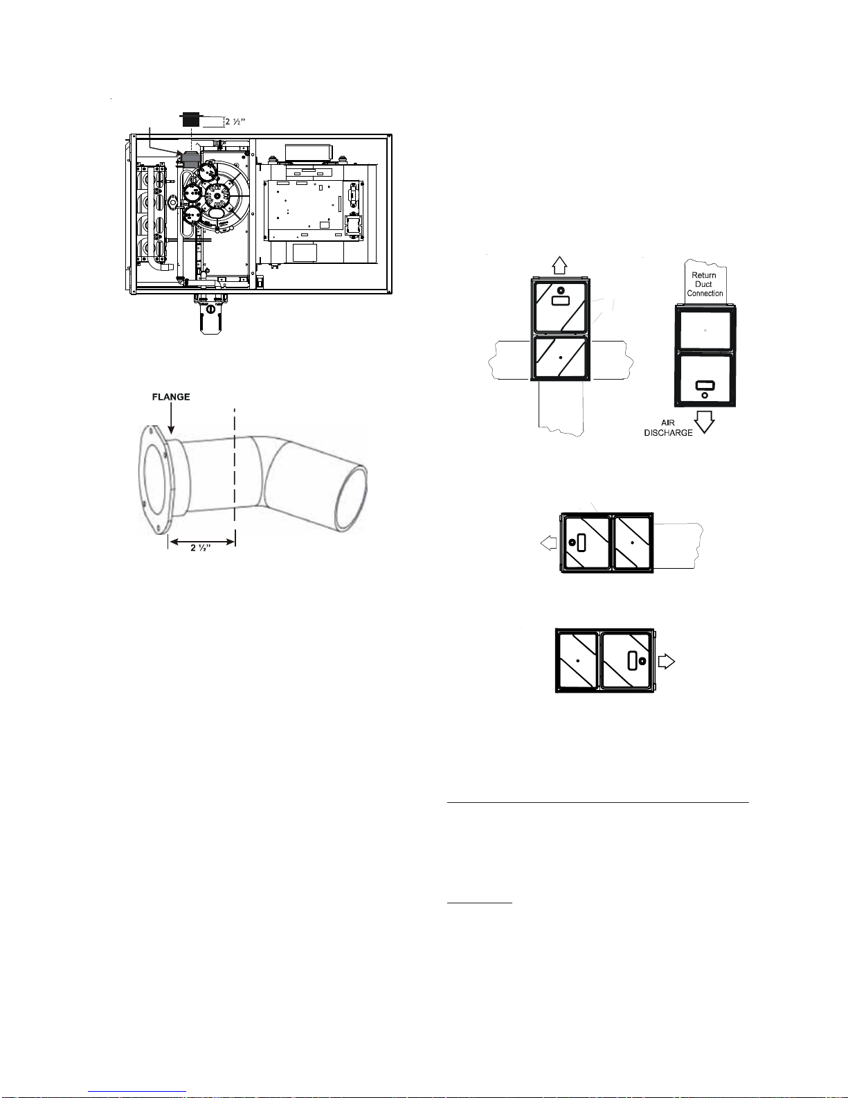
Installation Positions
*MEC96 models may be installed up flow or horizontally
with left or right side down. *CEC96 models may be installed down flow or horizontally with left or right side down.
Do not install any furnace on its back.
Horizontal Applications and Considerations
Horizontal applications, in particular, may dictate many of
the installation’s specifics such as airflow direction, ductwork connections, flue and/or combustion air pipe connections, etc. The basic application of this furnace as a horizontal furnace differs only slightly from an upright installation.
Horizontal Installations
1. Horizontal installations require 5.5" under the furnace
to accommodate the drain trap.
2. Horizontal furnaces must be installed with ¾” slope from
back to front to permit condensate flow towards the
front of the furnace.
When installing horizontally with the left side down, there
are two options for connecting the vent pipe to the furnace.
1. Venting may be connected to the furnace vent pipe fitting on the original top (now the end) of the furnace
2. The internal vent pipe and elbow may be removed from
the furnace to permit the vent to exit the top (original
side) of the furnace. If this option is used, an RF000142
Vent-Drain coupling must be used to keep condensate
from collecting in the inducer assembly
Refer to the following instructions and illustration.
9.3.8.3 Ducts shall serve a single space.
16
Page 17
SYSTEM OPERATION
A
A
Insert fl ange. Cut 2 ½” long.
R 000142F
Leveling
Leveling ensures proper condensate drainage from the heat
exchanger and induced draft blower. For proper flue pipe
drainage, the furnace must be level lengthwise from end to
end. The furnace should also be level from back to front or
have a slight tilt with the access doors downhill (approximately 3/4") from the back panel. The slight tilt allows the
heat exchanger condensate, generated in the recuperator
coil, to flow forward to the recuperator coil front cover.
IR
DISCHARGE
Figure 9
E
R
E
H
T
U
C
Figure 10
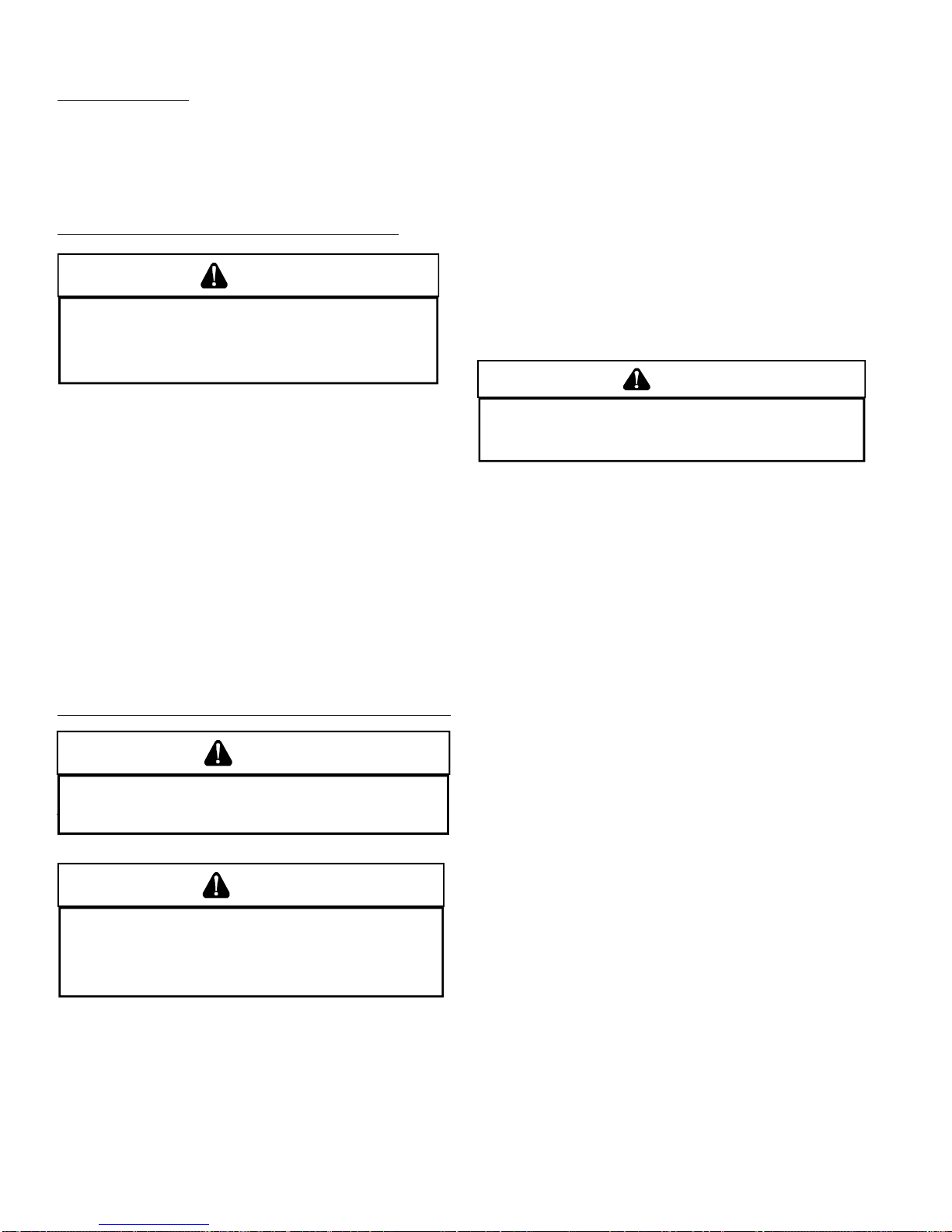
1. Remove screws from the vent flange.
2. Remove the internal elbow and vent pipe
3. Cut 2 1/2" from the flange .
4. Remove cabinet plug adjacent to inducer outlet and
install an original cabinet vent hole.
5. Install RF000142 coupling on inducer outlet.
6. Install flanged vent section removed in step 2 and secure with clamps.
7. Secure flange to cabinet using screws removed in step1.
Drain Trap and Lines
In horizontal applications the condensate drain trap is secured to the furnace side panel, suspending it below the
furnace. A minimum clearance of 5.5" below the furnace
must be provided for the drain trap. Additionally, the appropriate downward piping slope must be maintained from the
drain trap to the drain location. Refer to Condensate Drain
Trap and Lines section in this manual or the installation
instructions for further details. If the drain trap and drain line
will be exposed to temperatures near or below freezing,
adequate measures must be taken to prevent condensate
from freezing. NOTE: The use of insulation and/or heat tape
is recommended. Failure to provide proper condensate drainage can result in property damage.
Side
Return
Duct
Connection
Bottom
Return
Duct
Connection
Side
Return
Duct
Connection
UPFLOW
UPRIGHT
Counterflow
Bottom
Return
Duct
Connection
UPFLOW HORIZONTAL
LEFT AIR DI SCHA RGE
Bottom
Return
Duct
IR
DISCHARGE
UPFLOW HORIZONTAL
RIGHT AIR DISCHARGE
90% Furnace Recommended Installation Positions
Alternate Electrical and Gas Line Connections
The furnaces have provisions allowing for electrical and gas
line connections through either side panel. In horizontal applications the connections can be made either through the
“top” or “bottom” of the furnace.
Drain Pan
A drain pan must be provided if the furnace is installed above
a conditioned area. The drain pan must cover the entire area
under the furnace (and air conditioning coil if applicable).
17
Page 18
SYSTEM OPERATION
Freeze Protection
If the drain trap and drain line will be exposed to temperatures near or below freezing, adequate measures must be
taken to prevent condensate from freezing. NOTE: The use
of insulation and/or heat tape is recommended. Failure to
provide proper condensate drainage can result in property
damage.
Propane Gas and/or High Altitude Installations
WARNING
P
OSSIBLE PROPERTY DAMAGE, PERSONAL INJURY OR DEATH MAY OCCUR IF
THE CORRECT CONVERS ION KI TS ARE NOT I NST ALLED.
MUST BE APPLIED TO INSURE SAFE AND PROPER FURNACE OPERATION.
CONVERSIONS MUST BE PERF ORMED BY A QUALI F IE D INS TALLER O R SERV ICE
AGENCY.
This furnace is shipped from the factory configured for natural gas at standard altitude. Propane gas installations require an orifice change to compensate for the energy content difference between natural and propane gas.
High altitude installations may require both a pressure switch
and an orifice change. These changes are necessary to compensate for the natural reduction in the density of both the
gas fuel and the combustion air at higher altitude.
Refer to the Accessories Charts in this manual or product
Specification Sheet for a tabular listing of appropriate
manufacturer’s kits for propane gas and/or high altitude installations. The indicated kits must be used to insure safe
and proper furnace operation. All conversions must be performed by a qualified installer, or service agency.
VENT/FLUE PIPE AND COMBUSTION AIR PIPE
WARNING
FAILURE TO FOLLOW THESE INSTRUCTIONS CAN RESULT IN BODILY INJURY OR
DEATH.
ONLY)
CAREFU LL Y RE AD AN D FOL LO W AL L I NST RU CTI ON S GI VEN IN TH IS
SECTION.
WARNING
UPON COMPLETION OF THE FURNACE INSTALLATION, CAREFULLY INSPECT THE
ENTIRE FLUE SYSTEM BOTH INSIDE AND OUTSIDE THE FURNACE TO ASSURE IT
IS PROPERLY SEALED.
PERSONAL INJ URY O R DE ATH DUE TO E XPOSURE TO FLUE PRO DUCTS,
INCLUDING CARBON MONOXIDE.
LEAKS IN THE FLUE SYSTEM CAN RESULT IN SERIOUS
A condensing gas furnace achieves its high level of efficiency
by extracting almost all of the heat from the products of
combustion and cooling them to the point where condensation takes place. Because of the relatively low flue gas temperature and water condensation requirements, PVC pipe is
used as venting material.
This furnace must not be connected to Type B, BW, or L
vent or vent connector, and must not be vented into any
THE APPROPRIATE KIT S
ALL
portion of a factory built or masonry chimney except when
used as a pathway for PVC as described later in this section. Never common vent this appliance with another appliance or use a vent which is used by a solid fuel appliance.
It is the responsibility of the installer to follow the manufacturers’ recommendations and to verify that all vent/flue piping and connectors are compatible with furnace flue products. Additionally, it is the responsibility of the installer to
ensure that all piping and connections possess adequate
structural integrity and support to prevent flue pipe separation, shifting, or sagging during furnace operation.
Materials and Joining Methods
WARNING
O AVOID BODILY INJURY, FIRE OR EXPLOSION, SOLVENT CEMENTS MUST BE
T
KEPT AWAY FROM ALL IGNITION SOURCES (I.E., SPARKS, OPEN FLAMES, AND
EXCESSIVE HEAT) AS THEY ARE COMBUSTIBLE LIQUIDS.
CEMENT VAPORS OR CONTACT WITH SKIN AND/OR EYES.
VOID BREATHING
A
Precautions should be taken to prevent condensate from
freezing inside the vent/flue pipe and/or at the vent/flue
pipe termination. It is our recommendation that all vent/
flue piping exposed to temperatures below 35°F for
extended periods of time should be insulated with 1/2”
thick closed cell foam. Also all vent/flue piping exposed
outdoors in excess of the terminations shown in this manual
(or in unheated areas) should be insulated with 1/2” thick
closed cell foam. Inspect piping for leaks prior to installing
insulation.
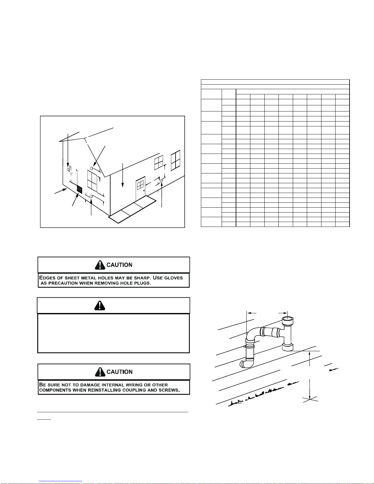
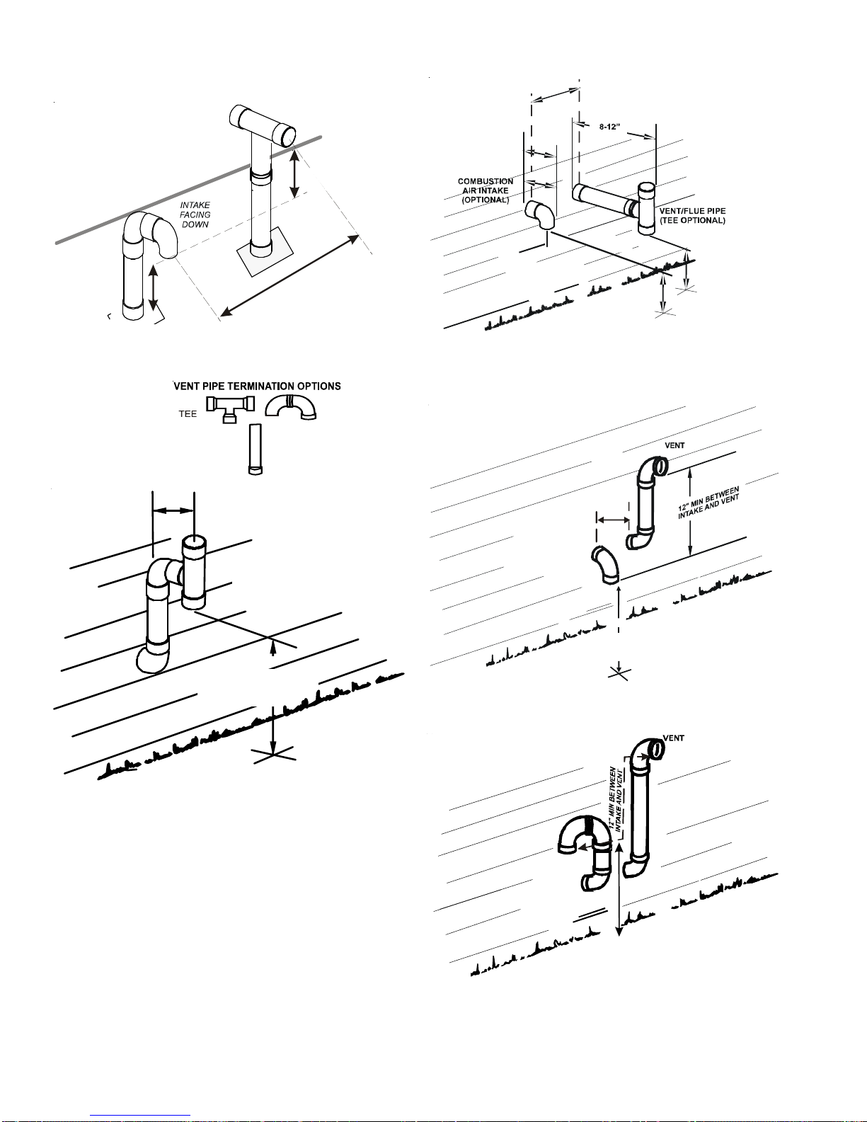
The following bullets and diagram describe the restrictions
concerning the appropriate location of vent/flue pipe and
combustion air intake pipe (when applicable) terminations.
Refer to or the installation instructions for specific details
on termination construction.
• All terminations must be located at least 12 inches
above ground level or the anticipated snow level.
• Vent terminations must terminate at least 3 feet
above any forced air inlet located within 10 feet.
NOTE: This provision does not apply to the combustion air intake termination of a direct vent application.
• The vent termination of a non-direct vent application
must terminate at least 4 feet below, 4 feet horizontally from, or 1 foot above any door, window, or gravity air inlet into any building.
• The vent termination of a direct vent application must
terminate at least 12 inches from any opening through
which flue gases may enter a building (door, window, or gravity air inlet).
• The vent termination of vent pipe run vertically through
a roof must terminate at least 12 inches above the
roof line (or the anticipated snow level) and be at
least 12 inches from any vertical wall (including any
anticipated snow build up).
18
Page 19
SYSTEM OPERATION
• A vent termination shall not terminate over public walkways or over an area where condensate or vapor
could create a nuisance or hazard or could be detrimental to the operation of regulators, relief valves, or
other equipment.
• The combustion air intake termination of a direct vent
application should not terminate in an area which is
frequently dusty or dirty.
NOTE: In Canada, the B149 Fuel Gas Code takes precedence over the preceding termination restrictions.
OTHER THAN
COMBUSTION AIR
TERMINATION INTAKE
NON-DIRECT VENT
VENT/FLUE TERM I NA TION
NO TERMINATIONS
ABOVE WALKWAY
GRADE OR HIGHEST
ANTICIPATED
SNOW LEV EL
FORCED AIR
INLET
10'
3"
VENT/FLUE TERMINATION
12"
12"
12"
DIRECT VENT
VENT/FLUE TERM INATION
4'
4'
12"
NON-DIRECT VENT
bustion air intake to prevent inadvertent blockage. The tee
or elbows used in the vent/flue termination must be included
when determining the number of elbows in the piping system.
(6)
(3) (5)
MODEL
*MEC960303AN
&
*MEC960403AN
*MEC960603AN
*MEC960302BN
&
*MEC960402BN
*MEC960603BN
*MEC960803BN
*MEC960804CN
*MEC961004CN
*MEC961005CN
*MEC961205DN
*CEC960403BN
*CEC960603BN
*CEC960803BN
*CEC961005CN
*MV C96/*CV C9 6 D irect V ent (2 - Pi p e) and Non-D irect V ent (1- Pi p e)
Maximum Allowable Length of Vent/Flue Pipe
12345678
2 7571676360565248
3 126 120 115 110 105 99 94 89
2 3733302622181511
3 107 102 96 91 86 81 75 70
2 100 95 90 85 80 75 70 65
3 168 161 154 147 140 133 126 119
2 5045403530252015
3 143 136 129 122 115 108 101 94
2 6055504540353025
3 113 106 99 92 85 78 71 64
2 6055504540353025
3 120 113 106 99 92 85 78 71
2 4540353025201510
3 103 96 89 82 75 68 61 54
2 4540353025201510
3 151 144 137 130 123 116 109 102
3 185 178 171 164 157 150 143 136
2 100 95 90 85 80 75 70 65
3 110 103 96 89 82 75 68 61
2 4540353025201510
3 110 103 96 89 82 75 68 61
2 353025201510 5NA
3 103 96 89 82 75 68 61 54
2 4540353025201510
3 110 103 96 89 82 75 68 61
Number of Elbows
^
^
Pipe Size
(4)
(in.)
90% Furnace Vent Termination Clearances
WARNING
HE RUBBER ELBOW IS NOT DESIGNED TO SUPPORAT A LOAD. WHEN THE
T
RUBBER ELBOW IS MOUNTED EXTERNALLY TO THE FURNACE CABINET,
EXTREME CARE MUST BE TAKEN TO ADEQUATELY SUPPORT FIELD-SUPPLIED
VENT/FLUE PIPING, AS DAMAGE CAN RESULT IN LEAKS CAUSING BODILY
INJURY OR DEATH DUE TO EXPOSURE TO FLUE GASES, INCLUDING CARBON
MONOXIDE.
Vent/Flue Pipe Lengths (Non-Direct Vent) and Diameters
Refer to the following tables for applicable length, elbows,
and pipe diameter for construction of the vent/flue pipe system of a non-direct vent installation. In addition to the vent/
flue pipe, a single 90° elbow must be secured to the com-
1) Maximum allowable limits listed on individual lengths for inlet and flue and NOT a combination.
2) Minimum requirement for each vent pipe is five (5) feet in length and one elbow/tee.
3) Tee used in the vent/flue termination must be included when determining the number of elbows in
the piping system.
4) 2 1/2” or 3” diameter pipe can be used in place of 2” diameter pipe.
5) Increased Clearance Configurations using (2) 45 deg. Long Sweep elbows should be considered equivalent to one 90 deg. elbow.
6) One 90° elbow should be secured to the combustion air intake connection.
12" MINIMUM
VENT/FLUE TEE
OR
90° ELBOW TURNED
DOWN
12" MINIMUM ABOVE
HIGHEST ANTICIPATED
SNOW LEVEL
90% Furnace Horizontal Termination (Single Pipe)
Above Highest Anticipated Snow Level
NOTE: Terminate both pipes in the same pressure zone
(same side of roof, no major obstacles between pipes,
etc.).
19
Page 20
SYSTEM OPERATION
d
c
TEE (OPTIONAL)
COMBUSTION AIR INTAKE
(OPTIONAL)
*Not required for
single pipe installation
E
N
I
L
F
O
O
R
X
A
M
”
6
12” MIN TO ROOF OR HIGHEST
ANTICIPATED SNOW LEVEL
9
12” MIN
HEIGHT DIFFERENCE
BETWEEN
INTAKE AND VENT
.
N
I
M
”
3
-
.
10”- 24”
6” MAX
4” MIN
90º OR 45°
ELBOW
12" MIN. TO GRADE OR
HIGHEST ANTICIP AT ED
SNOW LEVEL
Standard Horizontal Terminations (Dual Pipe)
12" MIN.
Horizontal Termination (Single Pipe)
Above Highest Anticipated Snow Level
ELBOWS
STRAIGHT
VENT/FLUE TEE (
TURNED DO W N or
90° ELBOW TURNE D
or
45° ELBOW
DOWN
12" MIN. ABOVE
HIGHEST ANTICI P ATED
SNOW LEVEL
OPTIONAL)
90°
ELBOWS
3” - 24”
12" MIN. ABOVE
HIGHEST ANTICIPA TED
SNOW LEVEL
Alternate Horizontal Vent Termination (Dual Pipe)
90°
ELBOWS
20
3”-24” BETWEEN PIPES
12"MIN.ABOVE
HIGHEST ANTICIPATED
SNOW LEVE L
Combustion Air Intake may also be snorkeled to obtain 12” min groun
learance.
AlternateVentTerminationAboveAnticipated SnowLevel
(DualPipe)
Page 21
SYSTEM OPERATION
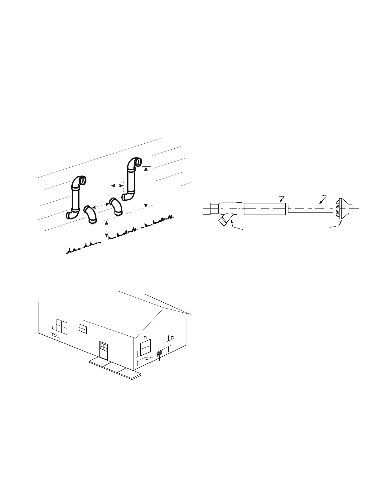
VENT/INTAKE TERMINATIONS FOR INSTALLATION OF MUL-
TIPLE DIRECT VENT FURNACES
If more than one direct vent furnace is to be installed vertically through a common roof top, maintain the same minimum clearances between the exhaust vent and air intake
terminations of adjacent units as with the exhaust vent and
air intake terminations of a single unit.
If more than one direct vent furnace is to be installed horizontally through a common side wall, maintain the clearances as in the following figure. Always terminate all exhaust vent outlets at the same elevation and always terminate all air intakes at the same elevation.
3”MIN
24”MAX
12” MIN SEPARATIO N
3” MIN
1. The vent termination must be located at least 12” above
ground or normally expected snow accumulation levels.
2. Do NOT terminate over public walkways. Avoid areas
where condensate may cause problems such as above
planters, patios, or adjacent to windows where steam
may cause fogging.
3. The vent termination shall be located at least 4’
horizontally from any electric meter, gas meter,
regulator and any relief equipment. These distances
apply ONLY to U.S. Installations.
4. The vent termination shall be located at least 3’ above
any forced air inlet located within 10’; and at least 10’
from a combustion air intake of another appliance,
except another direct vent furnace intake.
5. In Canada, the Canadian Fuel Gas Code takes
precedence over the preceding termination instructions.
3" or 4" Diameter
SDR-26 Pipe
2 or 2 1/2" Diameter
SDR-26 Pipe
12” MIN TO GRADE OR HIGHEST
ANT ICIP ATED SNOW LEVEL
Termination of Multiple Direct Vent Furnaces
9"
12"
Direct Vent
Terminal
50,000 Btuh
or less
12"
Direct Vent Terminal
More than 50,000 Btuh
FIGURE 1
(DCVK) Vent Termination Clearances
12"
Forc e d A ir Inlet
2" or 3" Diameter
2" or 3" Diameter
Y Concentric Fitting
Rain Cap
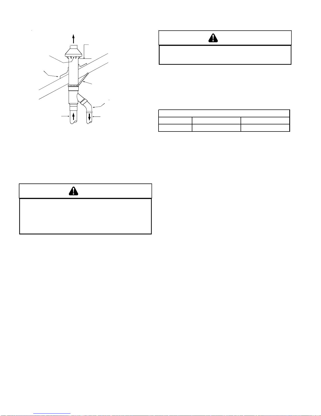
These kits are for vertical or horizontal termination of the
combustion air inlet and the exhaust vent pipes on Category
IV gas-fired condensing furnaces. The DCVK-30 (CVENT-
3) kit can be used for 3” diameter pipe systems. The DCVK-
20 (CVENT-2) kit can be used for the 2” diameter pipe
system. Both the combustion air inlet and the exhaust vent
pipes must attach to the termination kit. The termination
kit must terminate outside the structure and must be installed
per the instructions outlined below for vertical or horizontal
termination. Vertical termination is preferred. Field supplied
pipe and fittings are required to complete the installation.
3'
D
A
R
G
1. Determine the best location for the termination kit. Roof
E
termination is preferred since it is less susceptible to
damage, has reduced intake contaminants and less
visible vent vapors. For side termination, consideration
should be given to:
a. Possible damage from the vapors to plants/shurbs,
other equipment and building materials
b. Possible damage to the terminal from foreign ob-
jects
c. Wind effects that may cause recirculation of flue
products, debris or light snow
d. Visible vent vapors.
21
Page 22
SYSTEM OPERATION
Vent
Maintain 12" (18" for Canada)
minimum clearance above highest
anticipated snow level. Maximum of
Combustion Air
Roof Boot/Flashing
(Field Supplied)
24" above roof.
Support (Field Supplied)
45 Elbow
(Field Supplied)
CAUTION
O PREVENT UNRELI ABLE OPE RATION OR EQUIP MENT DAMAGE, THE INLE T
T
GAS SUPPLY PRESSURE MUST BE AS SPECIFIED ON THE UNIT RATING PLATE
WITH ALL OTHE R HOUSEHOL D GAS FIRED APPLIANCES O PERATING.
Inlet gas supply pressures must be maintained within the
ranges specified below. The supply pressure must be constant and available with all other household gas fired appliances operating. The minimum gas supply pressure must
be maintained to prevent unreliable ignition. The maximum
must not be exceeded to prevent unit overfiring.
Vent
Combustion Air
Condensate Drain Lines and Drain Trap
A condensing gas furnace achieves its high level of efficiency
by extracting almost all of the heat from the products of
combustion and cooling them to the point where condensation takes place. The condensate which is generated must
be piped to an appropriate drain location.
WARNING
N UPRIGHT UPFLOW INS TALLATIONS, THE DRA IN TRAP MUST BE MOUNTED ON
I
THE OPPOSITE S IDE OF THE UNIT FROM THE JUNC TION BOX.
REDUCE THE RIS K OF WATER REACH ING THE JUNCTION BOX I N THE EVENT OF
A BLOCKED DRAIN CONDITION.
CAN RESULT IN PO SSIBLE PROPE RTY DAMAGE, PERS ONAL INJURY, OR DEATH
DUE TO EL ECT RIC AL S HOC K.
AILURE TO FOLLOW THESE I NSTRUCTIONS
F
HIS WILL
T
• If the drain line is routed through an area which may
see temperatures near or below freezing, precautions must be taken to prevent condensate from
freezing within the drain line.
• If an air conditioning coil is installed with the
furnace, a common drain may be used. An open
tee must be installed in the drain line, near the
cooling coil, to relieve positive air pressure from the
coil’s plenum. This is necessary to prohibit any
interference with the function of the furnace’s drain
trap.
GAS SUPPLY AND PIPING
The furnace rating plate includes the approved furnace gas
input rating and gas types. The furnace must be equipped to
operate on the type of gas applied. This includes any conversion kits required for alternate fuels and/or high altitude.
INLET GAS SUPPLY PRESSURE
Natural Gas Minimum: 4.5" w.c. Maximum: 10.0" w.c.
Propane Gas Minimum: 11.0" w.c. Maximum: 13.0" w.c.
HIGH ALTITUDE DERATE
When this furnace is installed at high altitude, the appropriate High Altitude orifice kit must be applied. This is required due to the natural reduction in the density of both
the gas fuel and combustion air as altitude increases. The
kit will provide the proper design certified input rate within
the specified altitude range.
High altitude kits are purchased according to the installation altitude and usage of either natural or propane gas.
Refer to the product Specification Sheet for a tabular listing
of appropriate altitude ranges and corresponding
manufacturer’s high altitude (Natural, Propane gas, and/or
Pressure Switch) kits.
Do not derate the furnace by adjusting the manifold pressure to a lower pressure than specified on the furnace rating plate. The combination of the lower air density and a
lower manifold pressure will prohibit the burner orifice from
drawing the proper amount of air into the burner. This may
cause incomplete combustion, flashback, and possible yellow tipping.
In some areas the gas supplier may artificially derate the
gas in an effort to compensate for the effects of altitude. If
the gas is artificially derated, the appropriate orifice size
must be determined based upon the BTU/ft
3
content of the
derated gas and the altitude. Refer to the National Fuel
Gas Code, NFPA 54/ANSI Z223.1, and information provided
by the gas supplier to determine the proper orifice size.
A different pressure switch may be required at high altitude
regardless of the BTU/ft3 content of the fuel used. Refer to
the product Specification Sheet for a tabular listing of appropriate altitude ranges and corresponding manufacturer’s
pressure switch kits.
22
Page 23

SYSTEM OPERATION
PROPANE GAS CONVERSION
WARNING
P
OSSIBLE PROPERTY DAMAGE, PERS ONAL INJURY OR DEATH MAY OCCUR IF
THE CORRECT CONVERSION KITS ARE NOT INST ALLED.
MUST BE APPLIED TO I NSURE SAFE AND P ROPER FURNACE OPERATION.
CONVERSIONS MUST BE PERFORMED BY A QUALIFIED INSTALL ER OR SERVICE
AGENCY.
HE APPROPRIATE KITS
T
A
LL
This unit is configured for natural gas. The appropriate
manufacturer’s propane gas conversion kit, must be applied
for propane gas installations.
Refer to the specification sheet for the model you are servicing. Refer to the “propane gas and/or High Altitude Installa-
tions” section for details.
GAS VALVE
This unit is equipped with a 24 volt gas valve controlled during furnace operation by the integrated control module. As
shipped, the valve is configured for natural gas. The valve is
field convertible for use with propane gas by using the appropriate propane gas conversion kit. Taps for measuring
the gas supply pressure and manifold pressure are provided
on the valve.
NOTE: The gas supply pressure on White-Rodgers "G/J"
model gas valve, can be checked with a gas pressure test
kit (Part #0151K00000S) available through our authorized
distributors.
The gas valve has a manual ON/OFF control located on the
valve itself. This control may be set only to the “ON” or “OFF”
position. Refer to the Lighting Instructions Label or the “Put-
ting the Furnace Into Operation” section of this manual or
the installation instructions for use of this control during start
up and shut down periods.
GAS PIPING CONNECTIONS
CAUTION
T
O AVOID POSSIBLE UNS ATISFACTORY OPERATION OR EQUIPMENT DAMAGE
DUE TO UNDERFIRING OF EQUIPMENT, USE THE PROPER SIZE OF
NATURAL/PROPANE GAS PIPING NEEDED WHEN RUNNI NG PIPE FRO M THE
METER/TANK TO THE FURNACE.
The gas piping supplying the furnace must be properly sized
based on the gas flow required, specific gravity of the gas,
and length of the run. The gas line installation must comply
with local codes, or in their absence, with the latest edition
of the National Fuel Gas Code, NFPA 54/ANSI Z223.1.
Natural Gas Capacity of Pipe
In Cubic Feet of Gas Per Hour (CFH)
Length of
Pip e in Feet
10
20
30
40
50
60
70
80
90
100
(Pr es s ur e 0.5 psi g or le s s and pres s ur e d r op of 0.3" W.C.; B as ed on 0. 60 S p ec ific
Gravity Gas)
CFH =
BTUH Furnace Input
Heating Value of Gas (BTU/Cubic Foot)
1/2" 3/ 4" 1" 1 1/4" 1 1/2"
132 278 520 1050 1600
92 190 350 730 1100
73 152 285 590 980
63 130 245 500 760
56 115 215 440 670
50 105 195 400 610
46 96 180 370 560
43 90 170 350 530
40 84 160 320 490
38 79 150 305 460
No minal Black Pipe Size
To connect the furnace to the building’s gas piping, the installer must supply a ground joint union, drip leg, manual
shutoff valve, and line and fittings to connect to gas valve. In
some cases, the installer may also need to supply a transition piece from 1/2" pipe to a larger pipe size.
The following stipulations apply when connecting gas piping. Refer to the following figures for typical gas line connections to the furnace.
1. Use black iron or steel pipe and fittings for the building piping.
2. Use pipe joint compound on male threads only. Pipe
joint compound must be resistant to the action of the
fuel used.
3. Use ground joint unions.
4. Install a drip leg to trap dirt and moisture before it can
enter the gas valve. The drip leg must be a minimum
of three inches long.
5. Install a 1/8" NPT pipe plug fitting, accessible for test
gage connection, immediately upstream of the gas
supply connection to the furnace.
6. Use two pipe wrenches when making connection to
the gas valve to keep it from turning. The orientation of
the gas valve on the manifold must be maintained as
shipped from the factory .
7. Install a manual shutoff valve between the gas meter
and unit within six feet of the unit. If a union is installed, the union must be downstream of the manual
shutoff valve, between the shutoff valve and the furnace.
8. Tighten all joints securely .
23
Page 24

SYSTEM OPERATION
GAS PIPING CHECKS
Before placing unit in operation, leak test the unit and gas
connections.
WARNING
O AVOID THE POSSIBLITY OF EXPLOSION OR FIRE, NEVER USE A MATCH
T
OR OPEN FLAME TO TEST FOR LEAKS.
Check for leaks using an approved chloride-free soap and
water solution, an electronic combustible gas detector, or
other approved testing methods.
NOTE: Never exceed specified pressures for testing. Higher
pressure may damage the gas valve and cause subsequent
overfiring, resulting in heat exchanger failure. Disconnect this
unit and shutoff valve from the gas supply piping system
before pressure testing the supply piping system with pressures in excess of 1/2 psig (3.48 kPa). Isolate this unit from
the gas supply piping system by closing its external manual
gas shutoff valve before pressure testing supply piping system with test pressures equal to or less than 1/2 psig (3.48
kPa).
Complete information regarding tank sizing for vaporization,
recommended regulator settings, and pipe sizing is available from most regulator manufacturers and propane gas
suppliers.
Refer to the following illustration for typical propane gas installations and piping.
First Stage
Regulator
200 PSIG
Maximum
5 to 15 PSIG
(20 PSIG Max.)
Continuous
Second Stage
Regulator
11" W.C.
Typical Propane Gas Installation
PROPANE GAS TANKS AND PIPING
WARNING
PROPANE GAS IS HEAVIER THAN AIR AND ANY LEAK ING GAS CAN SETTLE IN
ANY LOW AR EAS OR CO NFIN ED SPACE S.
PERSONAL INJ URY, OR DEATH DU E TO FI RE OR EXPLOSI ON CAUSED BY A
PROPANE GAS LEAK, INSTALL A GAS DETE CTION WARNING DEVICE.
O PREVENT PROPERTY DAMAGE,
T
A gas detecting warning system is the only reliable way to
detect a propane gas leak. Iron oxide (rust) can reduce the
level of odorant in propane gas. Do not rely on your sense of
smell. Contact a local propane gas supplier about installing
a gas detecting warning system. If the presence of gas is
suspected, please refer to the warning on this page.
All propane gas equipment must conform to the safety standards of the National Board of Fire Underwriters, NBFU
Manual 58.
For satisfactory operation, propane gas pressure must be
10 inch WC at the furnace manifold with all gas appliances
in operation. Maintaining proper gas pressure depends on
three main factors:
1. Vaporization rate, depending on temperature of the liquid, and “wetted surface” area of the container or containers.
2. Proper pressure regulation. (Two-stage regulation is recommended for both cost and efficiency).
3. Pressure drop in lines between regulators, and between
second stage regulator and the appliance. Pipe size will
depend on length of pipe run and total load of all appliances.
WARNING
I
F THE GAS FURNACE IS INS TALLED IN A BASEMENT, AN E XCAVATED
AREA OR A CONFINED SPACE, IT IS STRONG LY RECOMMENDED TO
CONTACT A PROPANE SUPPLIER TO INSTALL A GAS DETECTING
WARNING DEVICE IN CASE OF A GAS LEAK.
•
SINCE PROPANE GAS I S HEAVI ER THAN AIR, ANY LE AKING GAS C AN
SETTLE I N ANY LOW ARE AS OR CONFINED S PACES.
PROPANE GAS ODORANT MAY FADE, MAKING THE GAS UNDETECTABLE
•
EXCEPT WIT H A WARNING DEVI CE.
WARNING
AN UNDETECTED GAS LEAK WILL CREATE A D ANGER OF EXPLOSI ON
OR FIR E.
IF THE PRESENCE OF GAS IS SUSPECTED, FOLLOW THE
INSTRUCTIONS ON THE COVER OF THIS MANUAL.
COULD RESULT IN
SERIOUS PERSONAL INJURY OR DEATH.
FAILURE TO DO SO
24
Page 25

SYSTEM OPERATION
WARNING
F THE INFORMATION IN THESE INSTRUCTIONS IS NOT FOLLOWED EXACTLY, A
I
FIRE OR EXPLOSION MAY RE SULT CAUSING PROPERTY DAMAGE, PERSONAL
INJURY OR LOSS OF LIFE.
O NOT STORE OR USE GASOLINE OR OTHER FLAMMABLE VAPORS AND
–
D
LIQUIDS IN TH E VICINITY OF THIS OR ANY OTHER APPLIANCE.
–
WHAT TO DO IF YOU SMELL GAS
•
•
PHONE IN YOUR BUILDING.
•
PHONE.
•
DEPARTMENT.
–
NSTALLATION AND SERVICE MUST BE PERFORMED BY A QUALIF IED INS TALLER ,
I
SERVICE AGENCY OR THE GAS SUPPLIER.
Sizing Betw ee n First and Second Stage Regul ator*
Ma ximum P r op ane C apacit ies li ste d ar e ba sed on 2 p sig pr e ss ur e dr o p at 10 ps ig se ttin g.
C apa cities in 1,00 0 BT U/hour.
Pipe or
Tubing
Length
Feet
10 730 1,700 3,200 5,300 8,300 3,200 7,500
20 500 1,100 220 3,700 5,800 2,200 4,200
30 400 920 2,000 2,900 4,700 1,800 4,000
40 370 850 1,700 2,700 4,100 1,600 3,700
50 330 770 1,500 2,400 3,700 1,500 3,400
60 300 700 1,300 2,200 3,300 1,300 3,100
80 260 610 1,200 1,900 2,900 1,200 2,600
100 220 540 1,000 1,700 2,600 1,000 2,300
125 200 490 900 1,400 2,300 900 2,100
150 190 430 830 1,300 2,100 830 1,900
175 170 400 780 1,200 1,900 770 1,700
200 160 380 730 1,100 1,800 720 1,500
To convert to capacities at 15 psig settings - multi ply by 1.130
To convert to capacities at 5 psig settings - multiply by 0.879
Sizing Betw ee n Second or S ec ond Stage Re gulator & Appliance*
Maximum Pr op ane Capacities li ste d are ba sed on 1 /2" W.C. press u re drop at 11" W.C. setting.
C apa c it i es in 1, 00 0 BTU/ho ur .
Pipe or
Tubing
Len gth
Feet
10 39 92 199 329 501 2 75 567 1 ,071 2, 205 3,307
20 26 62 131 216 346 1 89 393 732 1,496 2,299
30 21 50 107 181 277 1 52 315 590 1,212 1,858
40 19 41 90 145 233 129 267 504 1,039 1,559
50 18 37 79 131 198 114 237 448 913 1,41 7
60 16 35 72 1,211 18 7 103 217 409 8 34 1,275
80 13 29 62 104 155 89 185 346 724 1,06 6
100 11 26 55 90 138 78 162 307 6 30 976
125 10 24 48 81 122 69 146 275 5 67 866
150 9 21 43 72 109 63 132 252 511 787
200 8 19 39 66 100 54 112 209 439 665
250 8 17 36 60 93 48 100 185 3 90 590
*Data in accordance with NFPA pam phlet No. 54
O NOT TRY TO LIGHT ANY APPLIANCE.
D
O NOT TOUCH ANY ELECTRICAL SWITCH; DO NOT USE ANY
D
MMEDIATELY CALL YOUR GAS SUPPLIER FROM A NEIGHBOR’S
I
FOLLOW THE GA S SUPPLIER ’S INSTRUCTI ONS.
F YOU CANNOT REACH YOUR G AS SUPPLIER, CALL T HE FIRE
I
Tubing Size, O.D. Type L
3/8" 1/2" 5/8" 3/4" 7/8" 1/2" 3/4"
Tubing Siz e, O.D. Type L
3/8" 1/2" 5/8" 3/4" 7/8" 1/2" 3/4" 1" 1-1/4" 1-1/2"
:
Nominal
Pi p e Size
Schedule 40
Nominal Pipe Size
Schedule 40
Propane Gas Piping Charts
When installing a propane storage tank, the contractor must
consider proper tank sizing, safety, efficiency, ground characteristics and aesthetics. For a residential customer, the
size may range from 100-1,000 gallons, depending on household use. Typically, a 500 gallon tank is ample for an average four-bedroom home. However, it is best to consult your
local propane supplier to ensure the proper sizing for propane storage requirements. Determining the correct tank
size for each household is a function of demand, economy,
efficiency and convenience. It is a process that requires cooperation between the propane supplier and customer.
ELECTRICAL CONNECTIONS
WARNING
TO AVOID THE RISK OF ELECTRICAL SHOCK, WIRING TO THE UN IT MUST BE
PROPERLY POLARIZED AND GROUNDED.
WARNING
HIGH VOLTAGE
D
ISCO NNECT ALL POWER BEFORE SERVI CING OR
INSTALLI NG THI S UNI T.
BE PRESENT.
DAMAGE, PERSONAL INJURY OR DEATH.
FAILURE TO DO SO MAY CAUSE PROPERTY
MULTIPLE POWER SOURCES MAY
CAUTION
L
ABEL ALL WIRES PRIOR TO DISCONNECTION WHEN SERVICING CONTROLS.
WIRING ERRORS CAN COUSE IMPR OPER AND DAN GEROUS OPERAT ION.
ERIFY PROPER OPERATION AFTER SERVICING.
V
WIRING HARNESS
The wiring harness is an integral part of this furnace. Field
alteration to comply with electrical codes should not be required. Wires are color coded for identification purposes.
Refer to the wiring diagram for wire routings. If any of the
original wire as supplied with the furnace must be replaced,
it must be replaced with wiring material having a temperature rating of at least 105° C. Any replacement wiring must
be copper conductor.
115 VOLT LINE CONNECTIONS
Before proceeding with electrical connections, ensure that
the supply voltage, frequency, and phase correspond to that
specified on the unit rating plate. Power supply to the furnace must be N.E.C. Class 1, and must comply with all
applicable codes. The furnace must be electrically grounded
in accordance with local codes or, in their absence, with the
latest edition of The National Electric Code, ANSI NFPA 70
and/or The Canadian Electric Code CSA C22.1.
25
Page 26

SYSTEM OPERATION
Use a separate fused branch electrical circuit containing
properly sized wire, and fuse or circuit breaker. The fuse or
circuit breaker must be sized in accordance with the maximum overcurrent protection specified on the unit rating plate.
An electrical disconnect must be provided at the furnace
location.
NOTE: Line polarity must be observed when making field
connections.
N
G
I
N
W
R
A
IN 90% FURNACE UPRIGHT UP FLOW INSTALLATIONS, THE DRA IN TRAP MUST
BE MOUNTED ON THE OPPOSITE SIDE OF THE UNIT FROM THE JUNCTION
BOX.
THIS WILL REDUCE THE RISK OF WATER REACHING THE JUNCTION
BOX IN THE EVENT O F A BLOCKED DRAIN CONDITION.
Connect hot, neutral, and ground wires as shown in the wiring diagram located on the unit’s blower door. Line polarity
must be observed when making field connections. Line voltage connections can be made through either the right or left
side panel.
The furnace is shipped configured for a right side (left side
for counterflow) electrical connection with the junction box
located inside the burner compartment. To make electrical
connections through the opposite side of the furnace, the
junction box must be relocated to the other side of the burner
compartment prior to making electrical connections.
ACCESSORY LOAD SPECIFICATIONS
Electronic
Air Cleaner
Humidifier
1.0 Amp maximum at 120 VAC
1.0 Amp maximum at 120 VAC
Turn OFF power to the furnace before installing any accessories. Follow the humidifier or air cleaner manufacturers’
instructions for locating, mounting, grounding, and controlling these accessories.
If it is necessary for the installer to supply additional line
voltage wiring to the inside of the furnace, the wiring must
conform to all local codes, and have a minimum temperature rating of 105°C. All line voltage wire splices must be
made inside the furnace junction box.
The integrated control module electronic air cleaner terminals (EAC) are energized with 115 volts whenever the circulator blower is energized.
24 VOLT THERMOSTAT WIRING
NOTE: Low voltage connections can be made through ei-
ther the right or left side panel. Wire routing must not interfere with circulator blower operation, filter removal, or routine
maintenance.
A 40 V.A. transformer and an integrated electronic control
are built into the furnace to allow use with most cooling equipment. Consult the wiring diagram located in this manual,
the installation manual, or on the blower door for further details of 115 Volt and 24 Volt wiring.
NOTE: Wire routing must not interfere with circulator
blower operation, filter removal, or routine maintenance.
WARNING
TO AVOID THE RISK OF ELECTRICAL SHOCK, INJ URY, OR DEATH, TH E
FURNACE MUST BE ELECTRICALLY GROUNDED IN ACCORDANCE WITH LOCAL
CODES OR, IN THEIR ABSENCE, WITH THE LATEST EDITION OF THE
NATIONAL ELECTRIC CODE .
115 VOLT LINE CONNECTION OF ACCESSORIES
(ELECTRONIC AIR CLEANER)
WARNING
HIGH VOLTAGE
D
ISCONNECT ALL POWER BEFORE SERVI CING OR
CHANGING A NY ELECT RICAL WIRIN G.
SOURCES MAY BE PRESENT.
PROPERTY DAMA GE, PERSONA L INJURY OR DEATH.
MULTIPLE POWER
FAILURE TO DO S O MAY CAUSE
THERMOSTAT WIRING
The *MEC96 furnace has W1 & W2 terminals for connection of a two stage heating thermostat. If desired, a thermostat with only one stage of heat may be used. As shipped,
the furnace S1-1 switch is OFF; S1-2 switch is ON. This is
the correct position to use a single stage heating thermostat with auto timing transition to high fire.
R
Furnace
R
Y C
Remote Condensing Unit
(Single-Stage Cooling)
Thermostat - Single -Stage Heating with Single-Stage Cooling
NOTE: To apply a single-stage Heating Thermostat, the
thermostat selector switch on the Integrated Control Module
must be set on single-stage.
Integrated
Control
Module
26
Page 27

SYSTEM OPERATION
r
R
Furnace
Integrated
Control
Module
Y C
Remo te Condensing Unit
(Single -St age Cool in g)
R
Thermostat - Two-Stage Heating with Single-Stage Cooling
Y2
Y
Y2
Remote Cond ensing Unit
(Two-Stage Cooling)
W1 W2
W1 W2
Furnace
Integrated
Control
Module
Thermostat - Two-Stage Heating with Two-Stage Cooling
Thermostat Wiring Diagrams
SINGLE-STAGE HEATING THERMOSTAT APPLICATION
A single-stage thermostat with only one heating stage may
be used to control this furnace. The application of a singlestage thermostat offers a timed transition from low to high
fire. The furnace will run on low stage for a fixed period of
time before stepping up to high stage to satisfy the
thermostat’s call for heat. The delay period prior to stepping up can be set at either a fixed 10 or 20 minute time
delay or a load based variable time between 1 and 12 minutes (AUTO mode). If the AUTO mode is selected, the control averages the cycle times of the previous three cycles
and uses the average to determine the time to transition
from low stage to high stage.
TWINNING
Using the “TWIN” terminals and proper wiring enables two
*MEC96 furnaces of the same model and size to be twinned.
Twinning allows simultaneous operation of two furnaces and
forces the indoor blower motors of each furnace to operate
synchronously into a common duct system. Using the twinning function will require only field installed wiring with no
external kits or parts.
· The staging DIP switches and speed tap DIP switches
must be set the same on both furnaces.
NOTE: Each furnace must be connected to its own 115 VAC
power supply. The L1 connection toeach furnace must be
in phase (connected to circuit breakers on the same 115
VAC service panel phase leg). To verify that the furnaces
are in phase, check from L1 to L1 on each furnace with a
voltmeter. If the furnaces are in phase, the voltage between
both furnaces will be ZERO.
Room
Thermostat
Y2
Y
W
W2
R
G
C
Furnace 1
Ylo
Y
W
W2
R
G
C
Furnace 2
Ylo
Y
W
W2
R
G
C
DIP Switch
Group
S1
* = Factory Posit ion
Purpose Switch Group Function
The rmostat
setup
Heating Fan Off
Del ay
*Factory Setting
Staging and Blower Off Delay DIP Switches PCBBF137
DIP S witch
Numbe
1, 2
3, 4
Stag in g and Blo w er Of f Delay Dip Sw itc hes PCBBF139
Heat Stagin g /
Blow er Heat Off
1 Stg Stat 10 min de lay ON OFF
S3
1 Stg Stat 20 min de lay ON ON
S3
Purpose
Delay
Delay
2 Sta ge S tat O FF OFF
Auto Off* ON*
90 OF F OFF
120 OFF ON
150 ON* O FF*
180 ON ON
10 Minutes 1 ON 2 OFF
20 Minutes 1 ON 2 ON
90 Seconds 3 OFF 4 OFF
120 Seconds 3 OFF 4 ON
150 Seconds 3 ON* 4 OFF*
180 Seconds 3 ON* 4 ON
Function
Auto 1 OFF* 2 ON*
2 Stage 1 OFF 2 OFF
Dip Sw itch
1234
CIRCULATOR BLOWER SPEED ADJUSTMENT
WARNING
HIGH VOLTAGE
ISCONNECT ALL POWER BEFOR CHANGING SPEED TAPS.
D
ULTIPLE POWER SOURCES MAY BE PRESENT. FAILURE TO DO
M
SO MAY CAUSE PROPERTY D AMAGE, PERSO NAL INJURY OR DEATH .
This furnace is equipped with a multi-speed ECM motor.
Two wiring harnesses connect the motor to the integrated
control board and furnace power supply. The line voltage
(115 VAC) power supply to the motor is constant and not
switched by the control board. Motor operation is also dependent on a 24 VDC signal on one of the four speed taps
on the motor. The airflow tables for heating and cooling
speeds show the relationship between airflow (CFM) and
external static pressure for each size furnace.
27
Page 28

SYSTEM OPERATION
WARNING
TO
AVOID PERSONAL INJURY OR DEATH DUE TO ELECTR ICA L SHOCK
TURN
OFF
POWER TO THE FURNACE BEFORE CHANGING SPEED TAPS
Circulator Blower Speed Facts
1. Motor speed Tap wiring must remain in factory position on the control board and motor.
2. There are 4 speed Tap wires to the motor T1, T2, T3,
T4.
3. There are 5 speeds available, depending on DIP switch
settings and found in air flow table for each size furnace.
4. Heating input (W1/ W2) always has priority over all
other thermostat input.
5. Cooling input (YLo/ Y) has priority over continuous fan
input.
6. Continuous fan input (G) has lowest priority.
*The blower speed wiring connections must remain in
factory position.
1. Refer to the air flow table for your specific model furnace.
2. If a cooling or heat pump condensing unit is being used
in conjunction with this furnace, the three DIP switches
in S2 are used to select the proper cooling speeds to
match the outdoor unit size. Typical CFM requirements
are 400 CFM / Ton.
1. Turn OFF power to the furnace.
2. Select the cooling blower speeds that match the installation requirements from the airflow table in this manual
or the Installation Manual, If factory cooling speeds do
not match the installation requirements, the dip switch
settings must be changed from factory position
3. Turn ON power to furnace.
4. Verify proper temperature rise in heat modes and CFM
in cooling modes
CIRCULATING AIR AND FILTERS
DUCTWORK - AIR FLOW
Duct systems and register sizes must be properly designed
for the C.F.M. and external static pressure rating of the furnace. Ductwork should be designed in accordance with the
recommended methods of "Air Conditioning Contractors of
America" manual D.
A duct system should be installed in accordance with Standards of the National Board of Fire Underwriters for the Installation of Air Conditioning, Warm Air Heating and Ventilating Systems, Pamphlets No. 90A and 90B.
,
.
A return air filter is not supplied with the furnace. The installer must supply a means of filtering all of the return air.
Filter(s) shall comply with UL900 or CAN/ULC-S111 Standards. If the furnace is installed without filters, and is not
covered by the warranty.
Upflow furnaces with air delivery of less than 1800 CFM:
Use one side return or one bottom return ductwork connection.
Upflow furnaces with air delivery of 1800 CFM or higher:
Use two side returns or one side return and one bottom
return connection.
Guide dimples locate the side and bottom return cutout locations. Use a straight edge to scribe lines connecting the
dimples. Cut out the opening on these lines. An undersized
opening will cause reduced airflow. For bottom return connection, remove the bottom of the cabinet before setting the
furnace on the raised platform or return air duct.
A closed return duct system must be used, with the return
duct connected to the furnace. NOTE: Ductwork must never
be attached to the back of the furnace. Supply and return
connections to the furnace may be made with flexible joints
to reduce noise transmission, if desired. If a central return
is used, a connecting duct must be installed between the
unit and the utility room wall so the blower will not interfere
with combustion air or draft. The room, closet, or alcove
must not be used as a return air chamber.
When the furnace is used in connection with a cooling unit,
the furnace should be installed in parallel with or on the
upstream side of the cooling unit to avoid condensation in
the heating element. With a parallel flow arrangement, the
dampers or other means used to control the flow of air must
be adequate to prevent chilled air from entering the furnace
and, if manually operated, must be equipped with means to
prevent operation of either unit unless the damper is in the
full heat or cool position.
When the furnace is heating, the temperature of the return
air entering the furnace must be between 55°F and 100°F.
UPRIGHT FILTER INSTALLATIONS
Depending on the installation and/or customer preference,
differing filter arrangements can be applied. Filters can be
installed in the central return register and a side panel external filter rack kit (upflow filter kit # EFR02 As an alternative a media air filter or electronic air cleaner can be used
as the requested filter. Refer to the following minimum filter
requirement charts for determination of the minimum filter
area to ensure proper unit performance. The following figures show possible filter locations.
28
Page 29

SYSTEM OPERATION
DIP SWITCH SETTINGS
Thermostat
Selection
Switches
Heating Fan
Off Delay
Heating
CFM
Switches
Cooling
CFM
Switches
PCBBF137 CONTROL BOARD DIP SWITCHES
1
S1
2
3
DIP
DIP
Switch
Numbe r
1, 2
3, 4
Purp os e
Heat
Staging /
Dela y
Blowe r
Hea t Off
Dela y
120 Se conds 3 OFF 4 ON
150 Se conds 3 ON* 4 OFF *
180 Se conds 3 ON* 4 ON
Switch
4
1
S3
1
2
Group
S1
2
* = Fa ctory Pos iti on
3
1
S2
2
3
Function
Auto 1 OFF* 2 ON*
10 Minute s 1 ON 2 OFF
20 Minute s 1 ON 2 ON
2 Stage 1 OFF 2 OFF
90 Se conds 3 OF F 4 OFF
Cooling
CFM
Switches
Heating
CFM
Switches
Continuous
Fan CFM
Switches
Thermostat
Selection
Switches
PCBBF139 CONTROL BOARD DIP SWITCHES
1
S1
2
3
4
1
S2
2
3
4
1
S3
Purpose
Thermostat
Setup
Heating Fan
Off Del a y
* FACTORY
SETTING
Switch
Group
1 Stg S tat 10 min delay ON OFF
S3
1 Stg S tat 20 min delay ON ON
S3
2
Function
2 Stage S tat OFF OFF
Auto OFF* ON*
90 OFF OFF
120 OFF ON
150 ON* OFF*
180 ON ON
Dip S wi tch
1234
Heating Fan
Off Delay
3
4
29
Page 30

SYSTEM OPERATION
Y
Y
Y
Y
Y
Y
Y
Y
F
F
F
DIP SWITCH SETTINGS
PCBBF137 PCBBF139 *MEC960303AN - COOLING
DIP Switches
S2-1 S2-2 S2-3
**OFF OFF OF F **OFF OFF OFF
ON OFF OFF ON OFF OFF
ON ON OFF / OFF ON ON ON ON OFF
OFF ON OFF^ OFF ON OFF^
OFF OFF ON^ OFF OFF ON^
NA OFF ON ON^
ON OFF ON ON OFF ON
ON ON ON^ ON ON ON^
PCBBF137 PCBBF139 *MEC960303AN - CONTINUOUS FAN
DIP Switches
NA
ALL POSITIONS NA
PCBBF137
DIP Swit ches
S3- 1 S3-2
**OFF OFF **OFF OFF
ON OFF ON OFF
ON ON ON ON
OFF ON OFF ON
PCBBF139
DIP Swit ches
S1- 4 S2 - 1
DIP Switches
S1-1 S1-2 S1-3
DIP Switches
S2-2 S2-3 S2-4
**OFF OFF OFF
ON OFF OF
ON ON OF
OFF ON OF
OFF OFF ON
OFF ON ON
ON OFF ON
ON ON ON
Static
Tstat Call CFM Rise CFM Rise CFM Rise CFM CFM CFM
W1
W2
W1
W2
W1
W2
W1
W2
0.1 0.2 0.3 0.4 0.5 0.6 0.7 0.8
CFM Rise CFM Rise
623 42 393 N/ A
755 35 627 45
653 40 507 N/ A
755 35 627 45
653 40 507 N/ A
914 28 805 32
914 28 805 32
1070 25 975 27
Static
0.1 0.2 0.3 0.4 0.5 0.6 0.7 0.8
Ts tat Call CFM CFM CFM CFM CFM CFM CFM CFM
Ylo
Ylo
Ylo
Ylo
Ylo
Ylo
Ylo
Ylo
Static
914 874 841 805
1070 1040 1005 975 942 915 883 849
653 597 552 507 460 410 366 326
914 874 841 805 772 732 696 657
653 597 552 507
1070 1040 1005 975
914 874 841 805
623 506 451 393 343 293 N/A N/A
914 874 841 805
653 597 552 507 460 410 366 326
623 506 451 393 343 293 N/A N/A
755 710 672 627
1070 1040
653 597 552 507
1005 975 942 915 883 849
672 627 491 447
0.1 0.2 0.3 0.4 0.5 0.6 0.7 0.8
772 732 696 657
460 410 366 326
942 915 883 849
772 732 696 657
772 732 696 657
582 534755 710 672 627 491 447
582 534
582 534755 710
460 410 366 326
491 447
Ts tat Call CFM CFM CFM CFM CFM CFM CFM CFM
G
G
G
G
G
G
G
G
G
623 506 451 393 343 293 N/A N/A
755 710 672 627 582 534 491 447
653 597 552 507 460 410 366 326
914 874 841 805 772 732 696 657
1070 1040 1005 975 942 915 883 849
623 506 451 393 343 293 N/A N/A
623 506 451 393 343 293 N/A N/A
623 506 451 393 343 293 N/A N/A
623 506 451 393 343 293 N/A N/A
*MEC960303AN - HEATING
506 N/A 451 N/A 343 N/A 293 N/A N/A
710 37 672 42 582 49 534 491 447
597 44 552 47 460 N/A 410 366 326
710 37 672 42 582 49 534 491 447
597 44 552 47 460 N/A 410 366 326
874 30 841 31 772 34 732 696 657
874 30 841 31 772 34 732 696 657
1040 25 1005 26 942 28 915 883 849
*NOT RECOMMENDED
**Factory Default
SINGLE STAGE COOLING^
30
Page 31

SYSTEM OPERATION
F
F
DIP SWITCH SETTINGS
PCBBF137 PCBBF139 *MEC960403AN - COOLING
DIP Switches
S2-1 S2-2 S3-3
**OFF OFF OFF **OFF OFF OFF
ON OFF OFF ON OFF OFF
ON ON OFF / OFF ON ON ON ON OFF
OFF ON OFF^ OFF ON OFF^
OFF OFF ON OFF OFF ON
NA OFF ON ON^
ON OFF ON ON OFF ON
ON ON ON^ ON ON ON^
DIP Switches
S1-1 S1-2 S1-3
Static
Ts tat Call CFM CFM CFM CFM CFM CFM CFM CFM
Ylo
Y
Ylo
Y
Ylo
Y
Ylo
Y
Ylo
Y
Ylo
Y
Ylo
Y
Ylo
Y
0.1 0.2 0.3 0.4 0.5 0.6 0.7 0.8
914 874 841 805 772 732 696 657
1070 1040 1005 975 942 915 883 849
653 597 552 507 460 410 366 326
914 874 841 805 772 732 696 657
653 597 552 507 460 410 366 326
1070 1040 1005 975 942 915 883 849
914 874 841 805 772 732 696 657
721 679 635 591 552 505 463 422
914 874 841 805 772 732 696 657
1191 1168 113 5 1112 10 8 1 10 5 5 10 2 4 998
653 597 552 507 460 410 366 326
721 679 635 591 552 505 463 422
1191 1168 113 5 1112 10 8 1 10 5 5 10 2 4 998
1091 1061 1026 996 962 936 903 869
1191 1168 113 5 1112 10 8 1 10 5 5 10 2 4 998
653 597 552 507 460 410 366 326
PCBBF137 PCBBF139 *MEC960403AN - CONTINUOUS FAN
DIP Switches
NA
ALL POSITIONS NA
PCBBF137
DIP Swit ches
S3- 1 S3-2
**OFF OFF **OFF OFF
ON OFF ON OFF
ON ON ON ON
OFF ON OFF ON
PCBBF139
DIP Swit ches
S1- 4 S2 - 1
Tstat Call CFM Rise CFM Rise CFM Rise CFM CFM CFM
S1-1 S1-2 S1-3
Static
W1
W2
W1
W2
W1
W2
W1
W2
DIP Switches
**OFF OFF OFF
ON OFF OF
ON ON OFF
OFF ON OF
OFF OFF ON
OFF ON ON
ON OFF ON
ON ON ON
Static
Ts tat Call CFM CFM CFM CFM CFM CFM CFM CFM
G
G
G
G
G
G
G
G
G
0.1 0.2 0.3 0.4 0.5 0.6 0.7 0.8
CFM Rise CFM Rise
721 48 591 N/A
1191 2 9 1112 31
653N/A 507N/A
1191 2 9 1112 31
653N/A 507N/A
914 38 805 43
914 38 805 43
1070 33 975 36
679 N/A 635 N/A 552 N/A 505 463 422
1168 30 1135 31 1081 32 1055 1024 998
597 N/A 552 N/A 460 N/A 410 366 326
1168 30 1135 31 1081 32 1055 1024 998
597 N/A 552 N/A 460 N/A 410 366 326
874 40 841 41 772 45 732 696 657
874 40 841 41 772 45 732 696 657
1040 34 1005 35 942 37 915 883 849
0.1 0.2 0.3 0.4 0.5 0.6 0.7 0.8
721 679 635 591 552 505 463 422
1191 1168 113 5 1112 10 8 1 10 5 5 10 2 4 998
653 597 552 507 460 410 366 326
914 874 841 805 772 732 696 657
1070 1040 1005 975 942 915 883 849
721 679 635 591 552 505 463 422
721 679 635 591 552 505 463 422
721 679 635 591 552 505 463 422
721 679 635 591 552 505 463 422
*MEC960403AN - HEATING
*NOT RECOMMENDED
**Factory Default
SINGLE STAGE COOLING^
31
Page 32

SYSTEM OPERATION
Y
Y
Y
Y
Y
Y
YloY
Y
Y
YloY
Y
Y
Y
Y
F
F
DIP SWITCH SETTINGS
PCBBF1 37 PCBBF 139 *MEC96060 3AN - COO L ING
DIP Switches
S2-1 S2-2 S3-3
DIP Sw itche s
S1-1 S1-2 S1-3
**OFF OFF OFF **OFF OFF OFF
ON OFF OFF ON OFF OFF
ON ON OFF / OFF ON ON ON ON OFF
OFF ON OFF^ OFF ON OFF ^
OFF OFF ON OFF OFF ON
NA OFF ON ON^
ON OFF ON ON OFF ON
ON ON ON ^ ON ON ON^
Static
Tstat Call CFM CFM CFM CFM CFM CFM CFM CFM
lo
lo
lo
lo
lo
lo
0.1 0.2 0.3 0.4 0.5 0.6 0.7 0.8
880 838 794 763
1056 1026 991 961 929 894 864 829
697 654 600 557
880 838 794 763 722 689 644 606
697 654 600 557 508 460 419 371
1056 1026 991 961
880 838 794 763
1254 1230 1199 1 171 11 39 1115 1086 1053
880 838 794 763 722 689 644 606
1330 1301 1274 1244
697 654 600 557
1254 1230 1199 1 171 11 39 1115 1086 1053
1330 1301 1274 1244 1227 1191 1163 1132
1056 1026 991 961 929 894 864 829
1330 1301 1274 1244
697 654 600 557
PCBBF1 37 PCBBF 139 *MEC96060 3AN - CONTINUOUS F AN
DIP Switches
DIP Sw itche s
S1-1 S1-2 S1-3
**OFF OFF OFF
ON OFF OF
ON ON OFF
NA
OFF ON OF
OFF OFF ON
OFF ON ON
ON OFF ON
ON ON ON
ALL POSITIONS NA
Static
Tstat Call CFM CFM CFM CFM CFM CFM CFM CFM
G
G
G
G
G
G
G
G
G
0.1 0.2 0.3 0.4 0.5 0.6 0.7 0.8
12 54 1230 119 9 1171 113 9
1330 1301 1274 1244 1227 1191 1163 1132
697 654 600 557 508 460 419 371
880 838 794 763 722 689 644 606
1056 1026 991 961 929 894 864 829
1254 1230 1199 1 171 11 39 1115 1086 1053
1254 1230 1199 1 171 11 39 1115 1086 1053
1254 1230 1199 1 171 11 39 1115 1086 1053
1254 1230 1199 1 171 11 39 1115 1086 1053
722 689 644 606
508 460 419 371
929 894 864 829
722 689 644 606
1227 1191 1163 1132
508 460 419 371
1227 1191 1163 1132
508 460 419 371
1115 1086 1053
PCBBF137 PCBBF139
DIP Swit ches
S3 -1 S3- 2
**OFF OFF **OFF OFF
ON OFF ON OFF
ON ON ON ON
OFF ON OFF ON
DI P Swit ches
S1-4 S2 - 1
Static
Tstat Call CFM Rise CFM Rise Rise CFM Rise
W1
W2
W1
W2
W1
W2
W1
W2
*NOT RECOMMENDED
**Factory Default
SINGLE STAGE COOLING^
*MEC960603AN - HE ATING
0.1 0.2 0.3 0.4 0.5 0.6 0.7 0.8
CFM Rise CFM
1254 42 1171
1330 39 1244
697 N/A 557
1330 39 1244
697 N/A 557
880 N/A 763
880 N/A 763
1056 49 961
1230 42 1199 43 44 1139 46 1115 1086
1301 39 1274 41 42 1227 42 1191 1163 1132
654 N/A 600 N/A N/A 508 N/A 460 419 371
1301 39 1274 41 42 1227 42 1191 1163 1132
654 N/A 600 N/A N/A 508 N/A 460 419 371
838 N/A 794 N/A N/A 722
838 N/A 794 N/A N/A 722 N/A 689 644
1026 51 997 52 54 929 56 894 864 829
CFM CFM CFM
N/A 689 644
1053
606
606
32
Page 33

SYSTEM OPERATION
DIP SWITCH SETTINGS
PCBBF139
DIP Switches
S1-1 S1-2 S1-3
**OFF OFF OFF
ON OFF OFF
ON ON OFF
OFF ON OFF^
OFF OFF ON^
OFF ON ON
ON OFF ON
ON ON ON^
*CEC960403BN - CO O L I NG
Static
Tsta t Call CFM CFM CFM CFM CFM CFM CFM CF M
Ylo
Y
Ylo
Y
Ylo
Y
Ylo
Y
Ylo
Y
Ylo
Y
Ylo
Y
Ylo
Y
0.1 0.2 0.3 0.4 0.5 0.6 0.7 0.8
647 576 511 449 387 335 280 252
1229 1181 1150 1117 1078 1035 1002 964
1137 1096 1056 1018 981 940 897 859
647 576 511 449 387 335 280 252
1137 1096 1056 1018 981 940 897 859
1229 1181 1150 1117 1078 1035 1002 964
647 576 511 449 387 335 280 252
743 688 628 572 515 459 408 364
647 576 511 449 387 335 280 252
939 894 846 806 759 706 661 614
1137 1096 1056 1018 981 940 897 859
743 688 628 572 515 459 408 364
939 894 846 806 759 706 661 614
1229 1181 1150 1117 1078 1035 1002 964
939 894 846 806 759 706 661 614
1137 1096 1056 1018 981 940 897 859
PCBBF139
DIP Switches
S2-2 S2-3 S2-4
**OFF OFF OFF
ON OFF OFF
ON ON OFF
OFF ON OFF
OFF OFF ON
OFF ON ON
ON OFF O N
ON ON ON
PCBBF139
DIP Switches
S1-4 S2 -1
**OFF OFF
*ON OFF
*ON ON
OFF ON
Static
Tstat Call CFM Rise CFM Rise CF M Rise CFM Ri se CFM Rise CF M CFM CFM
*CEC960 403 BN - CO NTI NUOUS FAN
Static
Tstat CallCFMCFMCFMCFMCFMCFMCFMCFM
G
G
G
G
G
G
G
G
W1
W2
W1
W2
W1
W2
W1
W2
743 33 688 36 628 40 572 44 515 48 459 408 364
939 38 894 40 846 42 806 44 759 47 706 661 614
1137 NA 1096 NA 1056 NA 1018 NA 981 N/A 940 897 859
939 38 894 40 846 42 806 44 759 47 706 661 614
1137 NA 1096 NA 1056 NA 1018 NA 981 N/A 940 897 859
647 55 576 NA 511 NA 449 NA 387 NA NA NA NA
647 38 576 43 511 49 449 55 387 64 335 280 252
1229 29 1181 30 1150 31 1117 32 1078 33 10 35 1002 964
0.1 0.2 0.3 0.4 0.5 0.6 0.7 0.8
743 688 628 572 515 459 408 364
939 894 846 806 759 706 661 614
1137 1096 1056 1018 981 940 897 859
647 576 511 449 387 335 280 252
1229 1181 1150 1117 1078 1035 1002 964
743 688 628 572 515 459 408 364
743 688 628 572 515 459 408 364
743 688 628 572 515 459 408 364
*CEC960403BN - HEATING
0.40.1 0.2 0.3
0.5
0.6 0.7 0.8
*NOT RECOMMENDED
**Factory De fault
SINGLE STAGE COOLING^
33
Page 34

SYSTEM OPERATION
DIP SWITCH SETTINGS
PCBBF137 PCBBF139
DIP Switches
S2-1 S 2-2 S 2 -3
**OFF OFF OFF **OFF OFF OFF
ON OFF OFF ON OFF OFF
ON ON OFF / OFF ON ON ON ON OFF
OFF ON OFF^ OFF ON OFF^
OFF OFF ON OFF OFF ON
NA OFF ON ON
ON OFF ON^ ON OFF ON^
ON ON ON^ ON ON ON^
DIP Switches
S1-1 S 1-2 S 1 -3
PCBBF137 PCBBF139
DIP Switches
NA
ALL POSITIONS NA
DIP Switches
S2-2 S 2-3 S 2 -4
**OFF OFF OFF
ON OFF OFF
ON ON OFF
OFF ON OFF
OFF OFF ON
OFF ON ON
ON OFF ON
ON ON ON
*CEC960603BN - COO LI NG
Static
Tstat Ca ll CFM CFM CFM CFM CFM CFM CFM CFM
Ylo
Y
Ylo
Y
Ylo
Y
Ylo
Y
Ylo
Y
Ylo
Y
Ylo
Y
Ylo
Y
0.1 0.2 0.3 0.4 0.5 0.6 0.7 0.8
1149 1104 1057 1017 963 918 865 822
1236 1189 1149 1101 1066 1017 969 928
782 629 547 469 396 333 N/A N/A
1149 1104 1057 1017 963 918 865 822
782 629 547 469 396 333 N/A N/A
1236 1189 1149 1101 1066 1017 969 928
1149 1104 1057 1017 963 918 865 822
894 846 780 720 660 603 554 505
1149 1104 1057 1017 963 918 865 822
1328 1287 1249 1215 1170 1131 1085 1046
782 629 547 469 396 333 N/A N/A
894 846 780 720 660 603 554 505
1328 1287 1249 1215 1170 1131 1085 1046
1236 1189 1149 1101 1066 1017 969 928
1328 1287 1249 1215 1170 1131 1085 1046
782 629 547 469 396 333 N/A N/A
*CEC9 6 0 6 03 BN - CONT INUOUS F AN
Static
Tstat Ca ll CFM CFM CFM CFM CFM CFM CFM CFM
G
G
G
G
G
G
G
G
G
0.1 0.2 0.3 0.4 0.5 0.6 0.7 0.8
894 846 780 720 660 603 554 505
1328 1287 1249 1215 1170 1131 1085 1046
782 629 547 469 396 333 290 251
1149 1104 1057 1017 963 918 865 822
1236 1189 1149 1101 1066 1017 969 928
894 846 780 720 660 603 554 505
894 846 780 720 660 603 554 505
894 846 780 720 660 603 554 505
894 846 780 720 660 603 554 505
PCBBF137 PCBBF139
DIP Switches
S3-1 S3 -2
**OFF OFF **OFF OFF
ON OFF ON OFF
ON ON ON ON
OFF ON OFF ON
DIP Switches
S1-4 S2 -1
*NOT RECOMMENDED
**Factory De fault
SINGLE STAGE COOLING^
34
Static
Tstat Cal l CFM Rise CFM Rise CF M Rise CFM Rise CFM Rise CFM CFM CFM
W1
W2
W1
W2
W1
W2
W1
W2
0.1 0.2 0.3
894 41 846 44 780 47 720 51 660 56 603 554 505
1328 40 1287 41 1249 42 1215 43 1170 45 1131 1085 1046
782 47 629 NA 547 N/A 469 N/A 396 N/A N/A N/A N/A
1328 40 1287 41 1249 42 1215 43 1170 45 1131 1085 1046
782 47 629 NA 547 N/A 469 N/A 396 N/A N/A N/A N/A
1149 46 1104 48 1057 50 1017 52 963 55 918 865 822
1149 46 1104 48 1057 50 1017 52 963 55 918 865 822
1236 43 1189 44 1149 46 1101 48 1066 50 1017 969 928
*CEC960603BN - HEATING
0.4 0.5
0.6 0.7 0.8
Page 35

SYSTEM OPERATION
DIP SWITCH SETTINGS
PCBBF137 PCBBF139
DIP Switches
S2-1 S2-2 S2-3
**OFF OFF OFF
ON OFF OFF
ON ON OFF / OF F ON ON
OFF ON OFF
OFF OFF ON
NA
ON OFF ON^
ON ON ON^
S1-1 S1-2 S1-3
**OFF OFF OFF
PCBBF137 PCBBF139
DIP Switches
NA
ALL POSITIONS NA
S2-2 S2-3 S2-4
**OFF OFF OFF
DIP Switches
ON OFF OFF
ON ON OFF
OFF ON OFF
OFF OFF ON
OFF ON ON
ON OFF ON^
ON ON ON^
DIP Switches
ON OFF OFF
ON ON OFF
OFF ON OFF
OFF OFF ON
OFF ON ON
ON OFF ON
ON ON ON
**EC960803BN - COOLING
Stat ic
Tstat Call CFM CFM CF M CFM CFM CFM CFM CFM
Ylo
Y
Ylo
Y
Ylo
Y
Ylo
Y
Ylo
Y
Ylo
Y
Ylo
Y
Ylo
Y
0.1 0.2 0.3 0.4 0.5 0.6 0.7 0.8
894842784726682618562519
1111 1068 1025 984 941 885 860 801
750644569507442388328N/A
894842784726682618562519
750644569507442388328N/A
1111 1068 1025 984 941 885 860 801
894842784726682618562519
1221 1172 1128 1087 1049 1005 959 922
894842784726682618562519
1311 1293 1249 1203 1172 1122 1088 1041
750644569507442388328N/A
1221 1172 1128 1087 1049 1005 959 922
1311 1293 1249 1203 1172 1122 1088 1041
1111 1068 1025 984 941 885 860 801
1311 1293 1249 1203 1172 1122 1088 1041
750644569507442388328N/A
**EC960803BN - CONTINUOUS FAN
Static
Tstat Call CFM CFM CF M CFM CFM CFM CFM CFM
G
G
G
G
G
G
G
G
G
0.1 0.2 0.3 0.4 0.5 0.6 0.7 0.8
1221 1172 1128 1087 1049 1005 959 922
1311 1293 1249 1203 1172 1122 1088 1041
750 644 569 507 442 388 328 288
894 842 784 726 682 618 562 519
1111 1068 1025 984 941 885 860 801
1221 1172 1128 1087 1049 1005 959 922
1221 1172 1128 1087 1049 1005 959 922
1221 1172 1128 1087 1049 1005 959 922
1221 1172 1128 1087 1049 1005 959 922
PCBBF137 PCBBF139
DIP Switches
S3-1 S3-2
**OFF OFF
ON OFF*
ON ON*
OFF ON
DIP Switches
S1-4 S2-1
**OFF OFF
ON OFF*
ON ON*
OFF ON
Static
Tstat Call CFM Rise CFM Rise CFM Rise CFM Rise CFM Rise CFM CFM CFM
W1
W2
W1
W2
W1
W2
W1
W2
*NOT RECOMMENDED
**Factory Default
SINGLE STAGE COOLING^
0.10.20.30.40.5
**EC960803BN - HEATING
1221 40 1172 42 1128 44 10 87 45 1049 47 1005 959 922
1311 54 1293 54 1249 56 12 03 58 1172 60 1122 1088 1041
750 66 644 N/A 569 N/A 507 N/A 442 N/A 388 328 N/A
1311 54 1293 54 1249 56 12 03 58 1172 60 1122 1088 1041
750 N A 644 N/A 569 N/A 507 N/A 442 N/A 388 328 N/A
894 N/A 842 N/A 784 N/A 726 N/A 682 N/A 618 562 519
894 55 842 59 784 NA 726 NA 682 N/A 618 562 519
1111 63 1068 66 1025 69 984 NA 941 NA 885 N/A 801
0.6 0.7 0.8
35
Page 36

SYSTEM OPERATION
DIP SWITCH SETTINGS
PCBBF137 PCBBF139
DIP Switches
S2-1 S2-2 S2-3
**OFF OFF OFF
ON OFF OFF^
ON ON OFF / OF F ON ON
OFF ON OFF
OFF OFF ON
NA
ON OFF ON^
ON ON ON^
S1-1 S1-2 S1-3
**OFF OFF OFF
PCBBF137 PCBBF139
DIP Switches
NA
ALL POSITIONS NA
S2-2 S2-3 S2-4
**OFF OFF OFF
DIP Switches
ON OFF OFF^
ON ON OFF
OFF ON OFF
OFF OFF ON
OFF ON ON^
ON OFF ON^
ON ON ON^
DIP Switches
ON OFF OFF
ON ON OFF
OFF ON OFF
OFF OFF ON
OFF ON ON
ON OFF ON
ON ON ON
*MEC960804CN - COOLING
Stat ic
Tstat Call CFM CFM CF M CFM CFM CFM CFM CFM
Ylo
Y
Ylo
Y
Ylo
Y
Ylo
Y
Ylo
Y
Ylo
Y
Ylo
Y
Ylo
Y
0.1 0.2 0.3 0.4 0.5 0.6 0.7 0.8
1185 1121 1058 992 933 868 808 750
1727 1691 1642 1600 1545 1504 1449 1410
1408 1337 1279 1218 1167 1112 1062 999
1185 1121 1058 992 933 868 808 750
1408 1337 1279 1218 1167 1112 1062 999
1727 1691 1642 1600 1545 1504 1449 1410
1185 1121 1058 992 933 868 808 750
1281 1220 1152 1096 1031 978 914 856
1185 1121 1058 992 933 868 808 750
1839 1790 1757 1699 1665 1615 1568 1527
1408 1337 1279 1218 1167 1112 1062 999
1281 1220 1152 1096 1031 978 914 856
1839 1790 1757 1699 1665 1615 1568 1527
1727 1691 1642 1600 1545 1504 1449 1410
1839 1790 1757 1699 1665 1615 1568 1527
1408 1337 1279 1218 1167 1112 1062 999
*MEC960804CN - CONTINUOUS FAN
Static
Tstat Call CFM CFM CF M CFM CFM CFM CFM CFM
G
G
G
G
G
G
G
G
G
0.1 0.2 0.3 0.4 0.5 0.6 0.7 0.8
1281 1220 1152 1096 1031 978 914 856
1839 1790 1757 1699 1665 1615 1568 1527
1408 1337 1279 1218 1167 1112 1062 999
1185 1121 1058 992 933 868 808 750
1727 1691 1642 1600 1545 1504 1449 1410
1281 1220 1152 1096 1031 978 914 856
1281 1220 1152 1096 1031 978 914 856
1281 1220 1152 1096 1031 978 914 856
1281 1220 1152 1096 1031 978 914 856
PCBBF137 PCBBF139
DIP Switches
S3-1 S3-2
**OFF OFF
ON OFF*
ON ON*
OFF ON
DIP Switches
S1-4 S2-1
**OFF OFF
ON OFF*
ON ON*
OFF ON
Static
Tstat Call CFM Rise CFM Rise CFM Rise CFM Rise CFM Rise CFM CFM CFM
W1
W2
W1
W2
W1
W2
W1
W2
*NOT RECOMMENDED
**Factory De fault
SINGLE STAGE COOLING^
36
0.10.20.30.4
1281 39 1220 41 1152 43 10 96 45 1031 48 978 914 856
1839 39 1790 40 1757 40 16 99 42 1665 43 1615 1568 1527
1408 35 1337 37 1279 39 12 18 41 1167 43 1112 1062 999
1839 39 1790 40 1757 40 16 99 42 1665 43 1615 1568 1527
1408 35 1337 37 1279 39 12 18 41 1167 43 1112 1062 999
1185 NA 1121 NA 1058 NA 992 NA 933 NA NA NA NA
1185 42 1121 44 1058 47 992 50 933 53 868 1449 1410
1727 41 1691 42 1642 43 16 00 44 1545 46 1504 1449 1410
*MEC960804CN - HEATING
0.5
0.6 0.7 0.8
Page 37

SYSTEM OPERATION
DIP SWITCH SETTINGS
PCBBF137 PCBBF139
DIP Switches
S2-1 S2-2 S2-3
**OFF OFF OFF
ON OFF OFF^
ON ON OFF / OF F ON ON
OFF ON OFF
OFF OFF ON
NA
ON OFF ON^
ON ON ON^
S1-1 S1-2 S1-3
**OFF OFF OFF
PCBBF137 PCBBF139
DIP Switches
NA
ALL POSITIONS NA
S2-2 S2-3 S2-4
**OFF OFF OFF
DIP Switches
ON OFF OFF^
ON ON OFF
OFF ON OFF
OFF OFF ON
OFF ON ON^
ON OFF ON^
ON ON ON^
DIP Switches
ON OFF OFF
ON ON OFF
OFF ON OFF
OFF OFF ON
OFF ON ON
ON OFF ON
ON ON ON
*MEC961004CN - COOLING
0.1 0.2 0.3 0.4 0.5 0.6 0.7 0.8
CFM CFM CFM CFM CFM CFM CFM CFM
Ylo
Y
Ylo
Y
Ylo
Y
Ylo
Y
Ylo
Y
Ylo
Y
Ylo
Y
Ylo
Y
1312 1235 1170 1101 1037 962 880 820
1772 1713 1662 1609 1540 1498 1452 1399
1004 890 805 710 620 553 474 406
1312 1235 1170 1101 1037 962 880 820
1004 890 805 710 620 553 474 406
1772 1713 1662 1609 1540 1498 1452 1399
1312 1235 1170 1101 1037 962 880 820
1522 1464 1402 1338 1280 1230 1167 1101
1312 1235 1170 1101 1037 962 880 820
1861 1803 1749 1698 1653 1594 1549 1504
1004 890 805 710 620 553 474 406
1522 1464 1402 1338 1280 1230 1167 1101
1861 1803 1749 1698 1653 1594 1549 1504
1772 1713 1662 1609 1540 1498 1452 1399
1861 1803 1749 1698 1653 1594 1549 1504
1004 890 805 710 620 553 474 406
*MEC961004CN - CONTINUOUS FAN
Static
Tstat Call CFM CFM CF M CFM CFM CFM CFM CFM
G
G
G
G
G
G
G
G
G
0.1 0.2 0.3 0.4 0.5 0.6 0.7 0.8
1522 1464 1402 1338 1280 1230 1167 1101
1861 1803 1749 1698 1653 1594 1549 1504
1004 890 805 710 620 553 474 406
1312 1235 1170 1101 1037 962 880 820
1772 1713 1662 1609 1540 1498 1452 1399
1522 1464 1402 1338 1280 1230 1167 1101
1522 1464 1402 1338 1280 1230 1167 1101
1522 1464 1402 1338 1280 1230 1167 1101
1522 1464 1402 1338 1280 1230 1167 1101
PCBBF137 PCBBF139
DIP Switches
S3-1 S3-2
**OFF OFF
ON OFF*
ON ON* ON ON*
OFF ON
DIP Switches
S1-4 S2-1
**OFF OFF
ON OFF*
OFF ON
Static
Tstat Call CFM Rise CFM Rise CFM Rise CFM Rise CFM Rise CFM CF M CFM
W1
W2
W1
W2
W1
W2
W1
W2
*NOT RECOMMENDED
**Factory De fault
SINGLE STAGE COOLING^
0.1 0.2 0.3 0.4 0.5 0.6 0.7 0.8
*MEC961004CN - HEATING
1522 40 1464 42 1402 44 13 38 46 1280 48 1230 1167 1101
1861 47 1803 49 1749 50 16 98 52 1653 53 1594 1549 1504
1004 NA 890 NA 805 N/A 710 N/A 620 N/A 553 474 406
1861 47 1803 49 1749 50 16 98 52 1653 53 1594 1549 1504
1004 NA 890 NA 805 N/A 710 N/A 620 N/A 553 474 406
1312 NA 1235 N/A 1170 N/A 1101 N/A 1037 N/A 962 880 820
1312 47 1235 50 1170 53 11 01 56 1037 59 962 880 820
1772 50 1713 51 1662 53 16 09 55 1540 57 1498 1452 1399
37
Page 38

SYSTEM OPERATION
DIP SWITCH SETTINGS
PCBBF139 * CEC961005CN - CO O LING
DIP Switches
S1-1 S1-2 S1-3
**OFF OFF OFF
ON OFF OFF
ON ON OFF
OFF ON OFF^
OFF OFF ON
OFF ON ON^
ON OFF ON
ON ON ON^
Static
Tsta t Call CFM CFM CF M CFM CFM CFM CFM CFM
Ylo
Y
Ylo
Y
Ylo
Y
Ylo
Y
Ylo
Y
Ylo
Y
Ylo
Y
Ylo
Y
1637 1577 1528 1467 1410 1369 1307 1256
2069 2009 1978 1932 1923 1876 1834 1773
1477 1422 1364 1301 1244 1190 1135 1078
1637 1577 1528 1467 1410 1369 1307 1256
1477 1422 1364 1301 1244 1190 1135 1078
2069 2009 1978 1932 1923 1876 1834 1773
1637 1577 1528 1467 1410 1369 1307 1256
1300 1234 1175 1109 1052 992 928 866
1637 1577 1528 1467 1410 1369 1307 1256
1866 1817 1774 1729 1684 1637 1593 1552
1477 1422 1364 1301 1244 1190 1135 1078
1300 1234 1175 1109 1052 992 928 866
1866 1817 1774 1729 1684 1637 1593 1552
2069 2009 1978 1932 1923 1876 1834 1773
1866 1817 1774 1729 1684 1637 1593 1552
1477 1422 1364 1301 1244 1190 1135 1078
0.10.20.30.40.50.60.70.8
PCBBF139
DIP Switches
S2-2 S2-3 S2-4
**OFF OFF OFF
ON OFF OFF
ON ON OFF
OFF ON OFF
OFF OFF ON
OFF ON ON
ON OFF O N
ON ON ON
PCBBF139
DIP Switches
S1-4 S2-1
**OFF OFF
ON OFF
ON ON*
OFF ON
Static
Tstat Call CFM Rise CFM Rise CF M Rise CFM Rise CF M Rise CF M CFM CF M
*CEC961 005 CN - CO NTI NUOUS FAN
Static
Tsta t Cal l CFM CFM CFM CFM CFM CFM CFM CFM
G
G
G
G
G
G
G
G
0.1 0.2 0.3 0.4 0.5 0.6 0.7 0.8
1300 47 1234 50 1175 52 1109 56 1052 59 992 928 866
W1
1866 47 1817 48 1774 50 1729 51 1684 52 16 37 1593 1552
W2
1477 42 1422 43 1364 45 1301 47 1244 49 11 90 1135 1078
W1
1866 47 1817 48 1774 50 1729 51 1684 52 16 37 1593 1552
W2
1477 42 1422 43 1364 45 1301 47 1244 49 11 90 1135 1078
W1
1637 54 1577 56 1528 58 1467 60 1410 62 13 69 1307 1256
W2
1637 38 1577 39 1528 40 1467 42 1410 44 13 69 1307 1256
W1
2069 43 2009 44 1978 44 1932 46 1923 46 18 76 1834 1773
W2
0.1 0.2 0.3 0.4 0.5 0.6 0.7 0.8
1300 1234 1175 1109 1052 992 928 866
1866 1817 1774 1729 1684 1637 1593 1552
1477 1422 1364 1301 1244 1190 1135 1078
1637 1577 1528 1467 1410 1369 1307 1256
2069 2009 1978 1932 1923 1876 1834 1773
1300 1234 1175 1109 1052 992 928 866
1300 1234 1175 1109 1052 992 928 866
1300 1234 1175 1109 1052 992 928 866
*CEC961005CN - HEATING
*NOT RECOMMENDED
**Factory De fault
SINGLE STAGE COOLING^
38
Page 39

SYSTEM OPERATION
DIP SWITCH SETTINGS
PCBBF137 PCBBF139
DIP Switches
S2-1 S2-2 S2-3
**OFF OFF OFF
ON OFF OFF^
ON ON OFF / OF F ON ON
OFF OFF ON
NA
ON OFF ON^
ON ON ON^
S1-1 S1-2 S1-3
**OFF OFF OFF
ON OFF OFF^
PCBBF137 PCBBF139
DIP Switches
NA
ALL POSITIONS NA
S2-2 S2-3 S2-4
**OFF OFF OFF
ON OFF OFF
OFF OFF ON
DIP Switches
ON ON OFF
OFF ON OFFOFF ON OFF
OFF OFF ON
OFF ON ON^
ON OFF ON^
ON ON ON^
DIP Switches
ON ON OFF
OFF ON OFF
OFF ON ON
ON OFF ON
ON ON ON
*MEC961005CN - COOLING
Stat ic
Tstat Call CFM CFM CF M CFM CFM CFM CFM CFM
Ylo
Y
Ylo
Y
Ylo
Y
Ylo
Y
Ylo
Y
Ylo
Y
Ylo
Y
Ylo
Y
0.1 0.2 0.3 0.4 0.5 0.6 0.7 0.8
1384 1324 1271 1204 1145 1088 1029 985
2008 1963 1944 1916 1876 1839 1801 1759
1438 1366 1309 1254 1163 1133 1077 1013
1384 1324 1271 1204 1145 1088 1029 985
1438 1366 1309 1254 1163 1133 1077 1013
2008 1963 1944 1916 1876 1839 1801 1759
1384 1324 1271 1204 1145 1088 1029 985
1283 1219 1162 1109 1036 974 917 864
1384 1324 1271 1204 1145 1088 1029 985
1811 1772 1733 1690 1644 1590 1551 1492
1438 1366 1309 1254 1163 1133 1077 1013
1283 1219 1162 1109 1036 974 917 864
1811 1772 1733 1690 1644 1590 1551 1492
2008 1963 1944 1916 1876 1839 1801 1759
1811 1772 1733 1690 1644 1590 1551 1492
1438 1366 1309 1254 1163 1133 1077 1013
*MEC961005CN - CONTINUOUS FAN
Static
Tstat Call CFM CFM CF M CFM CFM CFM CFM CFM
G
G
G
G
G
G
G
G
G
0.1 0.2 0.3 0.4 0.5 0.6 0.7 0.8
1283 1219 1162 1109 1036 974 917 864
1811 1772 1733 1690 1644 1590 1551 1492
1438 1366 1309 1254 1163 1133 1077 1013
1384 1324 1271 1204 1145 1088 1029 985
2008 1963 1944 1916 1876 1839 1801 1759
1283 1219 1162 1109 1036 974 917 864
1283 1219 1162 1109 1036 974 917 864
1283 1219 1162 1109 1036 974 917 864
1283 1219 1162 1109 1036 974 917 864
PCBBF137 PCBBF139
DIP Switches
S3-1 S3-2
**OFF OFF
ON OFF*
ON ON*
OFF ON
DIP Switches
S1-4 S2-1
**OFF OFF
ON OFF*
ON ON*
OFF ON
Static
Tstat Call CFM Rise CFM Rise CFM Rise CFM Rise CFM Rise CFM CFM CFM
W1
W2
W1
W2
W1
W2
W1
W2
*NOT RECOMMENDED
**Factory De fault
SINGLE STAGE COOLING^
0.1 0.2 0.3 0.4 0.5 0.6 0.7 0.8
*MEC961005CN - HEATING
1283 48 1219 51 1162 53 11 09 56 1036 59 974 917 864
1811 49 1772 50 1733 51 16 90 52 1644 54 1590 1551 1492
1438 43 1366 45 1309 47 12 54 49 1163 53 1133 1077 1013
1811 49 1772 50 1733 51 16 90 52 1644 54 1590 1551 1492
1438 43 1366 45 1309 47 12 54 49 1163 53 1133 1077 1013
1384 64 1324 NA 1271 NA 1204 NA 1145 NA 1088 1029 985
1384 44 1324 47 1271 48 12 04 51 1145 54 1088 1029 985
2008 44 1963 45 1944 45 19 16 46 1876 47 1839 1801 1759
39
Page 40

SYSTEM OPERATION
DIP SWITCH SETTINGS
PCBBF137 PCBBF139
DIP Switches
S2-1 S2-2 S2-3
**OFF OFF OFF
ON OFF OFF^
ON ON OFF / OF F ON ON
OFF ON OFF
OFF OFF ON
NA
ON OFF ON^
ON ON ON^
S1-1 S1-2 S1-3
**OFF OFF OFF
PCBBF137 PCBBF139
DIP Switches
NA
ALL POSITIONS NA
S2-2 S2-3 S2-4
**OFF OFF OFF
DIP Switches
ON OFF OFF^
ON ON OFF
OFF ON OFF
OFF OFF ON
OFF ON ON^
ON OFF ON^
ON ON ON^
DIP Switches
ON OFF OFF
ON ON OFF
OFF ON OFF
OFF OFF ON
OFF ON ON
ON OFF ON
ON ON ON
*MEC961205DN - COOLING
0.1 0.2 0.3 0.4 0.5 0.6 0.7 0.8
CFM CFM CFM CFM CFM CFM CFM CFM
Ylo
Y
Ylo
Y
Ylo
Y
Ylo
Y
Ylo
Y
Ylo
Y
Ylo
Y
Ylo
Y
1399 1327 1259 1185 1118 1051 980 913
1683 1628 1565 1511 1445 1387 1340 1276
1106 1017 946 855 764 681 605 N /A
1399 1327 1259 1185 1118 1051 980 913
1106 1017 946 855 764 681 605 N /A
1683 1628 1565 1511 1445 1387 1340 1276
1399 1327 1259 1185 1118 1051 980 913
1796 1753 1697 1645 1589 1536 1478 1425
1399 1327 1259 1185 1118 1051 980 913
2211 2162 2122 2076 2029 1986 1964 1942
1106 1017 946 855 764 681 605 N /A
1796 1753 1697 1645 1589 1536 1478 1425
2211 2162 2122 2076 2029 1986 1964 1942
1683 1628 1565 1511 1445 1387 1340 1276
2211 2162 2122 2076 2029 1986 1964 1942
1106 1017 946 855 764 681 605 N /A
*MEC961205DN - CONTINUOUS FAN
Static
Tstat Call CFM CFM CF M CFM CFM CFM CFM CFM
G
G
G
G
G
G
G
G
G
0.1 0.2 0.3 0.4 0.5 0.6 0.7 0.8
1796 1753 1697 1645 1589 1536 1478 1425
2211 2162 2122 2076 2029 1986 1964 1942
1106 1017 946 855 764 681 605 550
1399 1327 1259 1185 1118 1051 980 913
1683 1628 1565 1511 1445 1387 1340 1276
1796 1753 1697 1645 1589 1536 1478 1425
1796 1753 1697 1645 1589 1536 1478 1425
1796 1753 1697 1645 1589 1536 1478 1425
1796 1753 1697 1645 1589 1536 1478 1425
PCBBF137 PCBBF139
DIP Switches
S3-1 S3-2
**OFF OFF
ON OFF*
ON ON*
OFF ON
DIP Switches
S1-4 S2-1
**OFF OFF
ON OFF*
ON ON*
OFF ON
Static
Tstat Call CFM Rise CFM Rise CFM Rise CFM Rise CFM Rise CFM CFM CFM
W1
W2
W1
W2
W1
W2
W1
W2
*NOT RECOMMENDED
**Factory De fault
SINGLE STAGE COOLING^
40
0.10.20.30.40.5
*MEC961205DN - HEATING
1796 41 1753 42 1697 44 16 45 45 1589 47 1536 1478 1425
2211 48 2162 49 2122 50 20 76 51 2029 52 1986 1964 1942
1106 NA 1017 NA 946 N/A 855 N/A 764 N/A NA NA N/A
2211 48 2162 49 2122 50 20 76 51 2029 52 1986 1964 1942
1106 67 1017 73 946 N/A 855 N/A 764 N/A NA NA N/A
1399 NA 1327 N/A 1259 N/A 1185 N/A 1118 N/A NA NA NA
1399 53 1327 56 1259 59 11 85 62 1118 NA NA NA NA
1683 63 1628 65 1565 NA 1511 NA 1445 NA NA NA NA
0.6 0.7 0.8
Page 41

SYSTEM OPERATION
WARNING
TO
AVOID PERSONAL INJURY OR DEATH DUE TO ELECTRICAL SHOCK
TURN
OFF
POWER TO THE FURNACE BEFORE CHANGING SPEED TAPS
Circulator Blower Speed Facts
cuitry.
· Line polarity is checked.
,
.
· The control then enters standby waiting for a call for
heat or cool.
· The Furnace status LED will display a slow green
flash signaling standby mode
1. Motor speed Tap wiring must remain in factory position
on the control board and motor.
2. There are 4 speed Tap wires to the motor T1, T2, T3,
T4.
Refer to Minimum Filter Area tables to determine filter area
requirement. NOTE: Filters can also be installed elsewhere
in the duct system such as a central return.
Horizontal Installations
Filter(s) must be installed external to the furnace casing for
horizontal installations. For most installations it is preferable to use a central return with filters installed in the duct
behind the return air grill. In this way filter replacement is
relatively simple by merely removing the grille, rather than
going into the attic or crawl space.
ADDITIONAL FILTERING ACCESSORIES
External Filter Rack Kit (EFR02)
The external filter rack kit is intended to provide a location
external to the furnace casing, for installation of a permanent filter on upflow model furnaces. The rack is designed to
mount over the indoor blower compartment area of either
side panel, and provide filter retention as well as a location
for attaching return air ductwork.
Electronic Air Cleaner (ASAS and GSAS) or Media Air
Cleaner (AMU and GMU)
The electronic air cleaner and media air cleaner are multipositional high efficiency air filtration devices that can be
installed in any position, except with the access door facing
down. The best location for the air cleaner is in the return air
duct next to the blower compartment. Before installing the
air cleaner, consider the application. The electronic air cleaner
must be readily accessible for periodic inspection and cleaning of the pre-filters and electronic cells while the media air
cleaner must be readily accessible for periodic inspection
and replacement of the Media Air Cleaner (AMU and GMU)
filter cartridge (3 per carton) M0-1056, M1-1056, M2-1056,
M8-1056, to maintain maximum efficiency and trouble-free
operation. Carbon Filters 1156-3 and 1856-3 (set of 3) are
also available. See Product Catalog for exact filter for your
model. A full line of air filtration and indoor air quality products are available and can be seen at www.goodmanmfg.com.
SEQUENCE OF OPERATION
POWER UP:
· When power is supplied, the control will energize the
Red LED, microcomputer runs its self-check routine.
· The control will check the status of the gas valve cir-
HEAT MODE:
Call For 1st Stage Heat
· On a call for first stage heat, the thermostat contacts
close signaling the control module.
· The microcomputer runs its self-check routine.
· The Amber LED will display a slow flash signaling
normal heat operation.
· The control module checks the high limit (and/or auxiliary limit) switch(es) for normally closed contacts.
· The control checks the low pressure switch for a
shorted condition.
· The gas valve relay status is checked for proper operation. Once the low pressure switch is detected
open, the inducer blower is energized at high speed
and the humidifier is enabled.
· The low pressure switch is checked for closure.
· Once the low pressure switch is closed, the pre-purge
period begins. The inducer will be energized at high
speed for the pre-purge period.
· Following the completion of pre-purge, the inducer
switches to low speed and the igniter warm up period
begins.
· After completion of the igniter warm up period:
- Trial for ignition begins.
- The first stage of the gas valve is energized.
· The igniter is de-energized when flame is sensed or
at the conclusion of the ignition activation period (IAP),
whichever comes first.
· When flame is sensed, the delay to heat on period
begins timing.
· Retry counter is zeroed, if after 10 seconds the flame
is sensed:
- Control enters normal operating loop where all
inputs are continuously checked.
· After the delay to heat on period, the circulator fan is
energized at the low heat speed.
· The air cleaner will be energized with the circulator.
· If the call for heat is lost while the control is in the trial
for ignition period without flame being detected, the
control will turn off the gas valve and igniter. The control then enters the post-purge routine. The post-purge
time will be increased to 60 seconds. After completing the post-purge, the control resumes normal operation.
41
Page 42

SYSTEM OPERATION
CALL FOR 2ND STAGE AFTER FIRST STAGE:
. The inducer motor is enabled at high speed.
· The pressure switches are checked for closure. Closure of the second stage pressure switch will energize the high fire stage of the gas valve.
· The high speed circulator output is energized.
· NOTE: A call for 2nd stage without a call for 1st stage
will be ignored, and a three amber flash code will be
displayed on the LED. This error code will only be
stored in memory once during a single power cycle.
2ND STAGE SATISFIED, FIRST STAGE STILL
CALLED:
· When the second stage of the thermostat is satisfied,
the inducer blower is reduced to low speed which deenergizes the second stage of the gas valve.
· After the high heat off delay expires, the circulator is
reduced to low heat speed.
SIMULTANEOUS CALL FOR LOW AND HIGH HEAT
A call for both stages of heat will establish low fire before
going to high fire
Operation Using a Single Stage Heating Thermostat
Using a single stage thermostat, the options for high fire
delay are: 10 minutes; 20 minutes; or auto
· The automatic second stage logic is a method of energizing the second stage valve based on the recent
average of the heating duty cycle. During a typical
heating day there will be at least one call for heat
within a 3 hour period, and usually much more often.
During this mode the low to high stage delay is determined by using the average calculated duty cycle from
the table below. Once the specified delay time has
expired the second stage valve will be energized
· On the heating cycle following a period of 3 hours (or
greater) in which there is no call for heat, the second
stage valve will energize based on the average calculated duty cycle prior to the three hour no call for heat.
If the average calculated duty cycle is less than 50%,
then the low to high stage delay will be determined
from the table below. In this case, an assumption is
made that the outside temperature is fairly mild and
the long time between calls for heat was due to a low
thermal loss in the building. Going quickly to second
stage heat is not required in this instance.
· If the average calculated duty cycle is 50% or greater,
then the heating cycle will be treated as if high stage
is needed and the transition from low to high stage
delay will happen quickly. In this case an assumption
is made that the outside temperature is cold and that
the thermostat is likely coming out of setback. Since
assumptions are being made during this heating cycle
the duty cycle for this heat cycle will not be used in
the average calculate d duty cycle formula for future
heating cycles.
· The duty cycle is calculated every cycle and used
during the next cycle. The equation for the duty cycle
is calculated as follows: Duty Cycle = (Time the appropriate stage is ON) / (Time of the complete cycle).
· The average calculated duty cycle is determined by
averaging the previous average calculated duty cycle
with the duty cycle from the previous cycle. This places
a large emphasis on the previous cycle but allows a
large variation in any one duty cycle to be averaged
out after just a few complete heating cycles.
· If there is no load activity for 24 hours or more then
set the Duty Cycle = 100%
· The initial default average calculated duty cycle =
50%
Duty Cy c le % Valve O u t put Dem and
0-38 1
38-50 1
50-62 1
62-75 1
75-88 1
88-100 1
Purpose Switch Group Function
Heating Fan Off
Delay
Purpose Switch Group Function
Heating Fan Off
Delay
*Factory Setting
Stage, 12 m inute 2
st
Stage, 10 m inute 2
st
St age, 7 mi nut e 2
st
St age, 5 mi nut e 2
st
St age, 3 mi nut e 2
st
St age, 1 mi nut e 2
st
Blower Off Delay Dip Switches PCBBF137
90 OFF OFF
S1
Blower Off Delay Dip Switches PCBBF139
S3
120 O FF ON
150 ON* O FF*
180 ON ON
90 OFF OFF
120 O FF ON
150 ON* O FF*
180 ON ON
nd
nd
Stage Average
nd
St age Average to Heavy
nd
Stage Heavy
nd
Stage Heavy
nd
Stage Light
St age Light to Average
Dip S witch
1234
Dip S witch
1234
Heat Mode Blower Off Delay Timing
COOLING MODE:
LOW STAGE COOLING MODE SEQUENCE:
· On a call for lo cool, the Ylo and G thermostat contacts close signaling the control module.
· The LED will display a “GREEN”1 flash
· The compressor and condenser fan are energized. The
compressor is connected to the Ylo terminal of the
control module.
42
Page 43

SYSTEM OPERATION
· The circulator fan is energized at lo cool speed after a
cool on delay. The electronic air cleaner will also be
energized.
· After the thermostat is satisfied, the compressor is
de-energized
· Following the 60 second Cool Mode Fan Off Delay
period, the cool circulator and air cleaner relay are
de-energized.
· When the call for “Ylo”and “G”are presented simultaneously, the control will honor the Cool On delay and
keep the circulator de-energized. After the Cool On
delay, the circulator fan and air cleaner relays are
energized. The circulator fan is energized at the cool
speed. If a call for “G”is present prior to a call for “Ylo”,
the circulator will remain at the FAN circulator speed
during the Cool On delay.
SINGLE COOLING STAGE THERMOSTAT OR 2ND
STAGE COOLING MODE SEQUENCE.
· On a call for cool, the Y and G thermostat contacts
close signaling the control module.
· The LED will display a “GREEN”2 flash
· The compressor and condenser fan are energized. The
compressor is connected to the Y terminal of the control module.
· The circulator fan is energized at cool speed after a
cool on delay. The electronic air cleaner will also be
energized.
· After the thermostat is satisfied, the compressor is
de-energized and the Cool Mode FanOff Delay period
begins.
· Following the 60 second Cool Mode Fan Off Delay
period, the cool circulator and air cleaner relay are
de-energized
MANUAL FAN ON:
· On a call for Fan, the G thermostat contacts close
signaling the control module.
· The LED will display a solid “GREEN”
· When a call for G is received, the control will energize
the circulator in low heat speed after the fan on delay
time expires. The electronic air cleaner will also be
energized at this time.
· When the thermostat fan switch is moved to the ON
position, the circulator blower is energized at low heat
speed and the electronic air cleaner is also energized
· When the thermostat fan switch is moved back to the
AUTO position, the circulator fan and air cleaner relay
are de-energized and the control awaits a thermostat
call for heat or cool.
· Exception: During the Cool “On”delay, the control will
not respond to the fan input. If the fan was called prior
to the call for cool, the circulator will remain energized during the Cool “On”delay.
· If the fan is called prior to a call for heat, the circulator
will remain energized during the entire call for heat
sequence.
Combustion Quality
Combustion quality can be affected by several factors. Major
factors are venting and draining.
Venting
The venting system should be planned and installed with
the following in mind;
• Should not be longer than necessary
• Use 45°elbows rather than 90° elbows when possible
• Must not sag or otherwise trap condensate
• Use longest radius fittings possible
• If using 3" venting, make the transition from 2" to 3"
as close as practically possible
• Make sure there is no flue gas recirculation into the
combustion air pipe
Condensate Drainage
Furnace combustion can be affected if a furnace is holding
condensate. Check for proper connections of drain hoses,
make sure furnace condensate trap is clean. Make sure
furnace is not improperly sloped. Make sure air conditioning coil drain is not interfering with furnace drain.
Other Causes
1. Manifold Gas Pressure must be set for the gas being
used, Natural or L.P., high and low firing rates. If converted to L.P. gas, check size of all orifices
2. Remove Draft Inducer, Check the integrity of the gasket
between the inducer and the collector box cover, any air
leak here will have a negative effect on combustion.
Check the orifice hole in the collector box, it must be
free of burrs on both sides
3. Make sure burners are clean, not out of position and line
up correctly with exchanger tubes, including the heat
exchanger orifice plate between the burners and the heat
exchanger tubes, make sure it is not loose, missing a
screw or hanging down between the burners and heat
exchangers causing flame impingement.
4. Make sure the field installed gas line is not binding and
causing distortion of burner assembly
5. If the furnace is installed as a one pipe system; make
sure the surrounding area and structure are adequate to
provide combustion air
6. Make sure there are no cabinet air leaks allowing supply
air to affect combustion
7. If heat exchanger integrity is uncertain, follow procedures
in Service Bulletin SF-041
43
Page 44

ACCESSORIES
*CEC961005BNAA • • • • • • • • • • • TBD TBD TBD TBD TBD
* indicat es bot h AA and AB models
*CEC960603BNAA • • • • • • • • • TBD TBD TBD TBD TBD
*CEC960803BNAA • • • • • • • • • • • TBD TBD TBD TBD TBD
AMEC961005CNAB • • • • • • • • • • • 1 1
*CEC960403BNAA • • • • • • • • • • • TBD TBD TBD TBD TBD
*MEC960303ANA* • • • • • • • • • • • n/a n/a n/a n/a n/a
*MEC960403ANA* • • • • • • • • • • • 1 1
*MEC960603ANA* • • • • • • • • • • • 1 1
*MEC960302BNA* • • • • • • • • • • • n/a n/a n/a n/a n/a
*MEC960402BNA* • • • • • • • • • • • 1 1
*MEC960603BNA* • • • • • • • • • • • 1 1
*MEC960803BNA* • • • • • • • • • • • 1 1
*MEC961004CNA* • • • • • • • • • • • 1 1
*MEC961205DNA* • • • • • • • • • 1 1
AMEC960804CNAB • • • • • • • • • • • 1 1
DESCRIPTION
NUMBER
MODEL
EFR External Filter
Rack
Dual Fu el Kit
Media Air Cleaners
El ect ronic Air Cleaner
Counterflow
Su b base 17.5"
Counterflow
Su bbase 21"
Concentric Side Wall
Flush Mount Vent Kit
(3")
Concentric Side Wall
Flush Mount Vent Kit
(2")
Concentric Vent Kit
(2")
EFR02
AFE18-60A
AMU / GMU
ASAS / GSAS
CFSB17
CFSB21
0170K00000S
0170K00001S
DCVK-20
(CVENT-2)
*MEC 96 and *CEC96 Mod el Furnace A ccessories
Concentric Vent Kit
(3")
Propane Gas
Con ver si o n Kit
Propane Gas
Con ver si o n Kit
LP Low P r essure Sh ut
Off Kit
Ven t Drain Coupling
HASFK-1
1 =above 7000 f t
HASFK-2
HASFK-3
HASFK-1
HASFK-2
DCVK-30
(CVENT-3)
LPM30
LPM08
LPLP03
RF000142
High Altitude
Nat G as
High Altitude
Nat G as
High Altitude
Nat G as
High Altitude
LP Gas
High Altitude
LP Gas
44
Page 45

ACCESSORIES
EXTERNAL FILTER RACK KIT
EFR01 EXTERNAL FILTER RACK KIT
Used on Models
90% Upflow Model Fu rnaces
OF UNIT
( EFR02 )
FRONT
OF UNIT
BASE
UNIT SIDE
PANEL
RETURN AIR
CUTOUT AREA
SLOTS IN FILTER
CLEAR SCREWS
ON UNIT
BLOWER DECK
SCREWS
LOWER EDGE
SCREW
FILTER RACK ASSEMBLY
(FACE FILTER OPENING
TOWARDS FRONT
OF UNIT)
SIDE WALL VENT KIT
(0170K00000S/0170K00001S)
Description
This side wall only vent kit #0170K00000S is
to be used with 2” - 3” vent systems. The
#0170K00001S is a side wall vent kit that is to
used with 2" vent systems ONLY. This kit is
NOT intended for use with single pipe (indirect vent) installations.
The vent kit must terminate outside the structure and may be installed with the intake and
exhaust pipes located side-by-side or with one
pipe above the other.
See the section in this manual under "Vent
Flue and Combustion Air Pipe Terminations"
for more information or consult the Installation
Instructions (IO-635).
Horizontal Installation
Vertical Installation
45
Page 46

ACCESSORIES
CONCENTRIC VENT CONVERSION KIT
( DCVK-20
( CVENT-2 ) ( CVENT-3 )
The DCVK-20 (2") or the DCVK30 (3") is a concentric vent kit
approved with furnaces listed in
this manual.
This concentric vent kit allows for
vertical or horizontal vent termination. The illustrations give a brief
view of the kit and its application.
See the section in this manual
under "Vent Flue and Combustion
Air Pipe Terminations" for more
information or consult the Installation and Operating Instructions
(IO-619*).
Roof Boot/Flashing
(Field Supplied)
DCVK-30 )
Combustion Air
Vent
Vent
Maintain 12" (18" for Canada)
minimum clearance above hig hest
anticipated snow level. Maximum of
24" above roof.
Support (Fie ld Supplied)
45 Elbow
(Field Supplied)
Combustion Air
Vent
Combus tion A ir
Strap
(Field Supplied)
45 Elbow
(Field Supplied)
DCVK
DCVK
(Vertical Installation)
Combustion Air
Vent
Flush to
1" maximum
46
(Horizontal Installation)
Page 47

ACCESSORY WIRING DIAGRAMS
HIGH VOLTAGE!
DISCONNECT ALL POWER BEFORE SERVICING OR INSTALLING THIS
UNIT. MULTIPLE POWER SOURCES MAY BE PRESENT. FAILURE TO
DO SO MAY CAUSE PROPERTY DAMAGE, PERSONAL INJURY OR DEATH.
ALL FUEL SYSTEM CONTROL BOARD - AFE1860A
POWER SUPPLY
INPUT
FURNACE DEMAND
OUTPUT
BLOWER FAN DEMAND
OUTPUT
POWER SUPPLY INPUT
(COMMON)
SECOND STAGE FURNACE
DEMAND OUTPUT
COMPRESSOR OUTPUT
SECOND STAGE
COMPRESSOR OUTPUT
REVERSING VALVE
OUTPUT
POWER SUPPLY OUT
TO THERMOSTAT
CALL FOR
REVERSING VALVE
CALL FOR
COMPRESSOR
CALL FOR
EMERGENCY HEAT
CALL FOR
BLOWER FAN
CALL FOR
FURNACE HEAT
POWER SUPPLY COMMON
OUT TO THER MOSTAT
CALL FOR 2ND STAGE
FURNACE HEAT
CALL FOR 2ND STAGE
COMPRESSOR
POWER SUPPLY OUT
TO HP CONTROL
HP CALL FOR FURNACE
(DURING DEFROST)
REVERSING
VALVE OUTPUT
COMPRESSOR
CONTACTOR OUTPUT
POWER SUPPLY COMMON
OUT TO HP C ON TR OL
ODT (OUTDOOR
THERMOSTAT)
2ND STAGE COMPRESSOR
DEMAND OUTPUT
F
U
R
N
A
C
E
T
H
E
R
M
O
S
T
A
T
H
E
A
T
P
U
M
P
R
W1
G
C
W2
Y
Y2
O
R
O
Y
E
G
W1
C
W2
Y2
R
W2
O
Y
C
OT-NO
OT-NC
OT-C
Y2
P1-8
P1-7
P1-4
P1-6
P1-5
P1-2
P1-3
P1-1
P2-2
P2-1
P2-7
P2-8
P2-5
P2-9
P2-3
P2-4
P2-6
P3-9
P3-8
P3-7
P3-2
P3-6
P3-3
P3-1
P3-4
P3-5
24VAC
24VAC
F1
3A
C
C
24VAC
C
POWER
SUPPLY
1.0K
6.8K
6.8K
+5VDC
E/W1
O
Y
+VDC
+5VDC
+VDC
K1
K2
Q1
MICROPROCESSOR
24VAC
+VDC
K4
Q2
W1-FURN
W2-HP
G-STAT
G-FURN
Y2-HP
Y2-STAT
Y2-FURN
Y-ST AT
Y-FURN
Y-HP
K3
BREAK FOR ODT
1 2
ALL FUEL SYSTEM CONTROL BOARD - AFE18-60A
This wiring diagram is for reference only. Not all wiring is as shown above.
Refer to the appropriate wiring diagram for the unit being serviced.
(For use with Heat Pumps in conjunction with 80% or 90% Single-Stage or Two-Stage Furnaces)
47
Page 48

SERVICING
SERVICE NUMBERS
S-1 CHECKING VOLT AGE................................................................................................................................. 55
S-2 CHECKING WIRING.................................................................................................................................... 55
S-3A THERMOSTA T AND WIRING ....................................................................................................................... 55
S-3B HEA TING ANTICIPA TOR .............................................................................................................................. 55
S-4 CHECKING TRANSFORMER AND CONTROL CIRCUIT.............................................................................. 56
S-16A CHECKING AIR CIRCULATOR BLOWER MOT OR (EEM) ........................................................................... 56
S-200 CHECKING DUCT STA TIC........................................................................................................................... 56
S-201 CHECKING TEMPERATURE RISE ............................................................................................................. 57
S-300 CHECKING PRIMARY LIMIT CONTROL...................................................................................................... 57
S-301 CHECKING AUXILIARY LIMIT CONTROL .................................................................................................... 58
S-302 CHECKING FLAME ROLLOUT CONTROL .................................................................................................. 60
S-303 INDUCED DRAFT BLOWER MOTOR.......................................................................................................... 60
S-304 CHECKING GAS VAL VE (REDUNDANT) .................................................................................................... 60
S-305 CHECKING MAIN BURNERS ...................................................................................................................... 61
S-308 CHECKING HOT SURFACE IGNIT OR ......................................................................................................... 64
S-309 CHECKING FOR FLASHBACK ................................................................................................................... 64
S-310 CHECKING PRESSURE SWITCH............................................................................................................... 64
S-31 1 HIGH ALTITUDE APPLICA TION (USA)......................................................................................................... 65
S-312 CHECKING FOR DELAYED IGNITION ........................................................................................................ 65
S-313 CHECKING INTEGRATED IGNITION CONTROL BOARDS........................................................................ 65
S-314 CHECKING FLAME SENSOR................................................................................................................... 66
48
Page 49

SERVICING
V
V
As more and more electronic's are introduced to the Heating Trade, Polarization of incoming power and phasing of
primary to secondary voltage on transformers becomes
more important.
Polarization has been apparent in the Appliance industry
since the introduction of the three prong plug, however, the
Heating Industry does not use a plug for incoming power,
but is hard wired.
Some of the electronic boards being used today, with flame
rectification, will not function properly and/or at all without
polarization of incoming power. Some also require phasing
between the primary and secondary sides of step-down
transformers.
CHECKING FOR PHASING - PRIMARY TO SECONDARY OF UNMARKED TRANSFORMERS*
METER READS
24 VOLTS
.
.
.
.
.
.
VOLT / OHM
METER
METER READS
120 VOLTS
VOLT / OHM
METER
INCOMING POWER
GND
METER READS
0 VOLTS
GND
VOLT / OHM
METER
THIS IS THE COMMON
OR NEUTRAL LEG
METER READS
120 VOLTS
THIS IS L1 OR THE
HOT POWER LEG
These then should be wired to the furnace accordingly.
D
N
G
VOLT / OHM
METER
C
R
N
L1
C
R
TRANSFORMER
D
N
G
SECONDARY
VOLT / OHM
METER
LINE VOLTAGE
(NEUTRAL)
PRIMARY
LINE VOLTAGE
L1 (HOT)
READS 144 VOLTS - OUT OF PHASE
OLT / OHM
METER
READS 96 VOLTS - IN PHASE
D
N
G
C
R
OLT / OHM
METER
N
L1
If meter reads approximately 96 volts - the primary to secondary are in phase - if reads approximately 144 volts out of
phase - reverse low voltage wires.
*NOTE: For flame rectification the common side of the secondary voltage (24 V) is cabinet grounded. If you were to bench
test a transformer the primary neutral and secondary common must be connected together for testing purposes.
Some transformers will display phasing symbols as shown
D
N
G
C
NEUTRAL
in the illustration to the left to assist in determining proper
transformer phasing.
Checking for polarization and phasing should become a
24 V
R
120 V
L1
habit in servicing. Let's start now.
NOTE: Newer integrated ignition controls have a diagnos-
tic flash code for reversed polarity (Refer to Troubleshoot-
PHASING SYMBOL
ing-Diagnostic Chart for LED Codes).
49
Page 50

SERVICING
Seconds
for On e
Revolution
1/4
cu/ft
1
One
CUBIC
FEET
G AS RATE -- CUBIC FEE T PER HOUR
Size of Test Dial
1/2
cu/ft1cu/ft2cu/ft5cu/ft
Seconds
for One
Revolution
1/4
cu/ft
1
Size of Test Dial
1/2
cu/ft1cu/ft2cu/ft5cu/ft
10
11
12
13
14
15
16
17
18
19
20
21
22
23
24
25
26
27
28
29
30
31
32
33
34
35
90 180 360 720 1800
82 164 327 655 1636
75 150 300 600 1500
69 138 277 555 1385
64 129 257 514 1286
60 120 240 480 1200
56 113 225 450 1125
53 106 212 424 1059
50 100 200 400 1000
47 95 189 379 947
45 90 180 360 900
43 86 171 343 857
41 82 164 327 818
39 78 157 313 783
37 75 150 300 750
36 72 144 288 720
34 69 138 277 692
33 67 133 265 667
32 64 129 257 643
31 62 124 248 621
30 60 120 240 600
-- -- 116 232 581
28 56 113 225 563
-- -- 109 218 545
26 53 106 212 529
-- -- 103 206 514
36
37
38
39
40
41
42
43
44
45
46
47
48
49
50
51
52
53
54
55
56
57
58
59
60
25 50 100 200 500
-- -- 97 195 486
23 47 95 189 474
-- -- 92 185 462
22 45 90 180 450
-- -- -- 176 439
21 43 86 172 429
-- -- -- 167 419
-- 41 82 164 409
20 40 80 160 400
-- -- 78 157 391
19 38 76 153 383
-- -- 75 150 375
-- -- -- 147 367
18 36 72 144 360
-- -- -- 141 355
-- -- 69 138 346
17 34 -- 136 340
-- -- 67 133 333
-- -- -- 131 327
16 32 64 129 321
-- -- -- 126 316
-- 31 62 124 310
-- -- -- 122 305
15 30 60 120 300
50
Page 51

SERVICING
Se rvice Problem No Heat Unsatisfact ory He a t
POSSIBLE CAUSE
DOTS IN AN ALYSIS
GUIDE INDICATE
"POSSIBLE CAUSE"
Power Failure
Blown Fuse
Loose Connection
Shor t ed or Broken W ires
No Low Voltage
Faulty Thermostat
Faulty Transforme r
Poo r or High Resistan ce Ground
Improper Heat Anticipator Setting
Improper Thermostat Location
Faulty L imit or Roll Out Switch
Faulty Flame S ensor
F au l ty Ig niti o n C o nt ro l
Gas Valve or Gas Suppl y S hu t Off
F au l ty In du ce d Dr af t Bl owe r
Faulty Blo wer Motor (PSC)
Broken or Shorted Ignitor
Di rty Flame Sensor, Low UA
Stu ck Ga s V a lv e
Faulty Gas Valve
Open Aux il i a r y Lim it
Improper Air Flow or Distribution
Cycl i ng on Limit
Delayed Ig ni t i on
Flashb ack
Orific e Size
Gas Pr es sure
Cracked H eat Exchan ger
Furnace Und ers ized
Furnace Ove rsiz ed
Faulty Pr essu r e Sw i t ch
Blocked or Restricted Flue
Open Rol l Out S witch
Bouncing On Pressure Switch
SYMPTOM
Burner Won't Igni te
System Will Not Start
Burner Ignites-Lock s Out
Burner Shuts Off prior to T'Stat being Satisfied
•
•
•
•
•
•••••
•
•
••
•
•••
•
••
••
•
•
•••
•••
••
••
•• •
••••
•••
••
•
Long Cycles
Short Cycles
Too Much Heat
Soot and /or Fum es
N ot Enough Hea t
•• ••
•• ••
•
•
•• •
•
••
•
•
Test Volta ge
Test Volta ge
Check Wiri ng
Check Wiri ng
Check T ransfor m er
Che ck Ther mostat
Check T ransfor m er
Measure Ground Resistance
Adjust Heat Anticipator Setting
Relocate Thermos tat
Test Contro l
Test Flame Sensor
Test Contro l
Turn Valves to On Position
Te st In du ce d Dr af t Mo to r
Test Blower Motor (PSC)
Test Ig nitor
Clean Flame Sensor
Replac e Gas Val v e
Replac e Gas Val v e
Reset Control
Check Duct Static
Chec k Cont rols & T emperature Rise
Test for Delayed Ignition
Test for Flashba ck
Check Orifices
Che ck Gas Pressure
Check Burner Flames
Replace with Proper Size Furnace
Replace with Proper Size Furnace
Test Pre ssur e Switch
Check Flue /Drawdown Pressure
Test Flame Roll Out Con trol
Test Negative Pressure
Test Method
Remedy
See Service Procedure Reference
S-1
S-4
S-2
S-3A
S-4
S-3A
S-4
S-17B
S-3B
S-316
S- 3 0 0 / S- 30 2
S-314
S-313
S-317
S-303
S-16A,B,C
S-308
S-314
S-304
S-304
S-301
S-200
S- 2 0 1 / S- 30 0
S-312
S- 3 0 9 / S- 31 1
S- 3 0 6 / S- 31 1
S-307
S-305
S-318
S-318
S-310
S-310
S-302
S-310
51
Page 52

TROUBLESHOOTING
Symptoms
•Furnace fails to operate
•Control board LED is off
Green
LED Code
•Non e •None •None
Amber
LED Code
Red
LED Code
Fault Description Check Cautions
•Defective disconnect switch
•defective door switch • No
115 volt power •No 24 v olt
power
•Determine cause and restore
proper high and low volt power
supply
•Confirm electrically safe
condition before
proceeding wi th repairs
•Furnace is waiting for a
call
•Furnace fan only is
runni ng
•Normal operation with
low stage call for cooling
(Ylo & G)
•Normal operation with
high or singl e stage call
for cooli ng (Y & G)
•Normal operation with
low stage call for heat
(W1)
•Normal operation with
high or single stage call
for heat
•Furnace does not
operate, three Amber
flashes on control board
•Furnace does not
operate, four Amber
flashes on control board
•Furnace does not
operate, rapid Amber
flashes on control board
•Solid ON •None •None
•Rapid Fl ash •None •None
•One
repe ati ng
flash
•Two
repe ati ng
flashes
•Non e
•Non e
•Non e
•Non e
•None •Rapid •None •Low flame sense current
•No ne •No ne
•No ne •No ne
•On e
repe ating
flash
•Two
repe ating
flashes
•Three
repe ating
flashes
•Fo ur
repe ating
flashes
•None
•None
•None •W2 call present without W1
•None
•Furnace is not receiving a
call
•Furnace is receiving a cal l for
fan (24 volts on G terminal
•Normal operation with low
stage call for cooling (Ylo & G)
•Normal operation with high
or single stage call for cooling
(Y & G)
•Normal operation with low
stage call for heat ( W1)
•Normal operation with high
or single stage call for heat
•Ylo or Y call present without
G
•None Required
•None Required
•None Required
•None Required
•None Required
•None Required
•Faulty thermostat or
thermostat wiring or
improperly connected
thermostat wires
•Faulty thermostat or
thermostat wiring or
improperly connected
thermostat wires
•Dirty / coated flame rod, poor
flame, improper gas pressure,
poor flame sense wire or
connections
•Confirm electrically safe
condition before
proceeding wi th work
•Confirm electrically safe
condition before
proceeding wi th work
•Confirm electrically safe
condition before
proceeding wi th work
•Confirm electrically safe
condition before
proceeding wi th work
•Confirm electrically safe
condition before
proceeding wi th work
•Confirm electrically safe
condition before
proceeding wi th work
•Confirm electrically safe
condition before
proceeding wi th repairs
•Confirm electrically safe
condition before
proceeding wi th repairs
•Clean flame rod with
steel wool. Confirm
electrically safe condition
before proceeding with
repairs
•Furnace does not
operate, one Red flash
on control board
•Furnace does not
operate, two Red
flashes on control board,
possible inducer
operation
•Furnace does not
operate, three Red
flashes on control board
•Non e •None
•Non e •None
•Non e •None
52
•One
repe ating
flash
•Two
repe ating
flashes
•Thre e
repe ating
flashes
•Flame sensed when no
flame should be present
•Pressure switch stuck closed
•Low fire pressure s witch
stuck open
•Gas valve stuck open,
improper wiring to gas valve,
shorted flame rod or wire
•Faulty pressure switch,
pressure swi tch wires shorted,
control board inducer relay
stuck closed
•Faulty pressure switch,
pressure switch or tubing or
wiring / connection, control
board inducer relay failed, vent
pipe restriction / excessive
elbows or length
•Confi rm electrical and
gas safe conditi ons
before proceeding with
repairs
•Confirm electrically safe
condition before
proceeding wi th repairs
•Confirm electrically safe
condition before
proceeding wi th repairs
Page 53

TROUBLESHOOTING
g cy
Symptoms
•Furnace does not
operate, four Red
flashes on control board
•Furnace does not
operate, five Red
flashes on control board
•Furnace does not
operate, six Red flashes
on control board
•Furnace does not
operate, seven Red
flashes on control board
•Furnace does not
operate, eight Red
flashes on control board
•Furnace does not
operate, nine Red
flashes on control board
•Furnace does not
operate, ten Red flashes
on control board
Green
LED Code
•Non e •No ne
•Non e •No ne
•Non e •No ne
•Non e •No ne
•Non e •No ne
•Non e •No ne
•Non e •No ne
Amber
LED Code
Red
LED Code
•Four
repe ati ng
flashes
•Five
repe ati ng
flashes
•Six
repe ati ng
flashes
•Seven
repe ati ng
flashes
•Eight
repe ati ng
flashes
•Nine
repe ati ng
flashes
•Ten
repe ati ng
flashes
Fault Description Check Cautions
•Open limit circuit, main
limit, aux limit, or roll out
switch
•Limit & rollout circuit open
for 15 minutes. Open control
board fuse or rollout switch
•Pressure switch cycling
lockout, pressure swi tch has
opened 5 times in the same
heatin
•Lockout - excessive retries
from flame not being proven
during trial for ignition
• Lockout - e xcessive recycl es
from flame proving being lost
after being proven
•Improper grounding or
reve rse polarity
•Gas valve current dete cted
with no call for heat
cle
•Temperature rise, duct static,
gas pressure, burner alignment,
orifice plate position, wiring to
all limits
•Control board fuse,
Temperature rise, duct static,
gas pressure, burner alignment,
orifice plate position, wiring to
all limits
•Excessive venting restriction,
leaking pressure swi tch tubing
•Gas pressure, gas valve, front
cover pressure switch, flame
rod
•Gas pressure, gas valve, front
cover pressure switch, flame
rod
•115 volt hot & ne utral supply
to furnace reve rsed, hot wire
(door switch & L1 on control
board) must read 115 volts to
ground & neutral. Neutral wire
should measure 0 volts to
ground
•Verify gas valve is not
receiving voltage from an
electrical short. If valve wiring
is corre ct replace control board
•Confirm electrically safe
condition before
proceeding with repairs
•Confirm electrically safe
condition before
proceeding with repairs
•Confirm electrically safe
condition before
proceeding with repairs
•Confirm electrical and
gas safe conditions
before proceeding with
repai rs
•Confirm electrical and
gas safe conditions
before proceeding with
repai rs
•Confirm electrically safe
condition before
proceeding with repairs
•Confirm electrical and
gas safe conditions
before proceeding with
repai rs
•Furnace does not
operate, eleven Red
flashes on control board,
inducer running
•Furnace does not
operate, twelve Red
flashes on control board
•Furnace does not
operate, control board
Red LED on solid
•Furnace does not
operate, control board
Red LED rapid flash
•Furnace does not
operate, control board
Red LED with three
double flashes
•Ele ven
•Non e •No ne
•Non e •No ne
•None •None •Solid ON •Control board internal fault •Replace control board
•None •None •Rapid Flash •Twinning error •Correct twinning wiring
•Non e •No ne
repe ati ng
flashes
•Twelve
repe ati ng
flashes
•Three
double
flashes
•Open limit switch circuit for
more than 5 minutes
•Control board igniter relay
not energizing igniter
•Second stage pressure
switch stuck open
•Re-set main power and check
indoor blower operation
•Replace control board
•Verify pressure switch
function & tubing, verify
inducer operating and pulling
enough vacuum to engage
switch
•Confirm electrically safe
condition before
proceeding with repairs
•Confirm electrically safe
condition before
proceeding with repairs
•Confirm electrically safe
condition before
proceeding with repairs
•Confirm electrically safe
condition before
proceeding with repairs
•Confirm electrically safe
condition before
proceeding with repairs
53
Page 54

DIAGNOSTIC CHART
Refer to the Troubleshooting Chart in the back of this manual
for assistance in determining the source of unit operational problems.
External Lockout
- A control lockout resulting from an external fault
sensed by the control, such as an unsuccessful recycle or retry period, or a limit trip. Once in External
Lockout, the control will shut down for a period of one
hour before attempting another trial for ignition.
Internal Lockout
- A failure internal to the control board.
FAULT RECALL
Retrieving Fault Codes
To retrieve fault codes, push and release the “LAST ERROR” button for more than 1/5 second and less than 5 seconds (the LED will indicate this period by solid GREEN for
1/5 second to 5 seconds). The LED will flash up to five stored
fault codes, beginning with the most recent. If there are no
fault codes in memory, the LED will flash two green flashes.
The control will flash the most recent error first and the oldest error last. If multiple faults exist there will be 2 seconds
between codes. Solid LED error codes will not be displayed.
Fault Code Reset
To clear the fault code memory, push and hold the “LAST
ERROR” button for more than 5 seconds and less than 10
seconds (the LED will indicate this period by RAPID GREEN
FLASH for 5 seconds to 10 seconds). The LED will flash
three green flashes when the memory has been cleared.
The ignition control is equipped with a momentary push button switch that can be used to display on the diagnostic
LED the last five faults detected by the control. The control
must be in Standby Mode (no thermostat inputs) to use the
feature.
Depress the push button switch for approximately 2 seconds. Release the switch when the LED is turned off. The
diagnostic LED will then display the flash codes associated
with the last five detected faults. The order of display is the
most recent fault to the least recent fault.
RESETTING FROM LOCKOUT
Furnace lockout results when a furnace is unable to achieve
ignition after three attempts during a single call for heat. It
is characterized by a non-functioning furnace and a one flash
diagnostic LED code. If the furnace is in “lockout”, it can be
reset in any of the following ways.
1. Automatic reset. The integrated control module will
automatically reset itself and attempt to resume normal
operations following a one hour lockout period.
2. Manual power interruption. Interrupt 115 volt power to
the furnace for 1 - 20 seconds.
3. Manual thermostat cycle. Lower the thermostat so
that there is no longer a call for heat then reset to previous setting. Interrupt thermostat signal to the furnace
for 1 - 20 seconds.
Page 55

SERVICING
S-1 CHECKING VOLTAGE
CHECKING THERMOSTAT, WIRING
AND ANTICIPATOR
WARNING
HIGH VOLTAGE
ISCONNECT ALL POWER BEFORE SERVICI NG OR
D
CHANGING ANY E LECTRI CAL WI RING.
SOURCES MAY BE PRESENT.
PROPERTY DAMAGE, PERS ONAL INJURY OR DEATH.
MULTIPLE POWER
FAILURE TO DO SO MAY CAUSE
1. Remove cover from the Junction Box and gain access to
incoming power lines.
With Power ON:
WARNING
INE VOLTAGE NOW PRESENT
L
2. Using a voltmeter, measure the voltage across the hot
and neutral connections.
NOTE: To energize the furnace, the Door Interlock Switch
must be engaged at this point.
3. No reading - indicates open wiring, open fuse, no
power, or faulty Door Interlock Switch from unit to
fused disconnect service. Repair as needed.
4. With ample voltage at line voltage connectors, ener-
gize the furnace blower motor by jumpering terminals
R to G on the integrated ignition control.
5. With the blower motor in operation, the voltage
should be 1 15 volts ± 10 percent.
6. If the reading falls below the minimum voltage, check
the line wire size. Long runs of undersized wire can
cause low voltage. If wire size is adequate, notify the
local power company of the condition.
7. After completing check and/or repair , replace Junc-
tion Box cover and reinstall the service panel doors.
8. Turn on electrical power and verify proper unit opera-
tion.
S-2 CHECKING WIRING
WARNING
DISCONNECT ALL POWER BEFORE SERVICING.
1. Check wiring visually for signs of overheating, damaged
insulation and loose connections.
2. Use an ohmmeter to check continuity of any suspected
open wires.
3. If any wires must be replaced, replace with AWM, 105°C.
2/64 thick insulation of the same gauge or its equivalent.
S-3A THERMOSTAT AND WIRING
WARNING
DISCONNECT ALL POWER BEFORE SERVICING.
1. Remove the blower compartment door to gain access
to the thermostat low voltage wires located at the furnace integrated control module terminals.
2. Remove the thermostat low voltage wires at the furnace
control panel terminal board.
3. Jumper terminals R to W (or W1 and W2 for two-stage
models) on the integrated ignition control.
With Power On (and Door Interlock Switch closed):
WARNING
INE VOLTAGE NOW PRESENT
L
4. Induced Draft Motor must run and pull in pressure
switch.
5. If the hot surface ignitor heats and at the end of the
ignitor warm-up period the gas valve opens and the
burners ignite, the trouble is in the thermostat or wiring.
6. With power off, check the continuity of the thermo-
stat and wiring. Repair or replace as necessary .
If checking the furnace in the air conditioning mode, proceed as follows.
7. With power off, Jumper terminals R to Y
8. Turn on the power .
9. If the furnace blower motor starts and the condensing
unit runs, then the trouble is in the thermostat or wiring. Repair or replace as necessary .
10. After completing check and/or repair of wiring and
check and/or replacement of thermostat, reinstall
blower compartment door.
1 1. Turn on electrical power and verify proper unit opera-
tion.
S-3B HEATING ANTICIPATOR
The heating anticipator on older thermostats is a wire wound
adjustable heater which is energized during the "ON" cycle
to help prevent overheating of the conditioned space.
The anticipator is a part of the thermostat and if it should
fail for any reason, the thermostat must be replaced. Modern thermostats do not have this type of heat anticipator.
Many have a selector switch to adjust the number of cycles
per hour.
55
Page 56

SERVICING
S-4 CHECKING TRANSFORMER AND Control CIR-
CUIT
A step-down transformer 120 volt primary to 24 volt secondary, 40 VA (Heating and Cooling Models) supplies ample
capacity of power for either operation.
WARNING
HIGH VOLTAGE
D
ISCO NNECT ALL POWER BEFORE SERVI CING OR
CHANGING ANY ELECTRICAL WIRING.
SOURCES MAY BE PRESENT.
PROPERTY DAMAGE, PERSONAL INJURY OR DEATH.
1. Remove blower compartment door to gain access to the
thermostat low voltage wires located at the furnace integrated control module.
2. Remove the thermostat low voltage wires at the furnace
integrated control module terminals.
With Power On (and Door Interlock Switch closed):
LINE VOLTAGE NOW PRESENT
3. Use a voltmeter, check voltage across terminals R
and C. Must read 24 V AC.
4. No voltage indicates faulty transformer , open fuse, bad
wiring, bad splice, or open door interlock switch.
5. Check transformer primary voltage at incoming line
voltage connections, fuse, splices, and blower door interlock switch.
6. If line voltage is available to the primary side of trans-
former and not at secondary side, the transformer is
inoperative. Replace.
7. After completing check and/or replacement of trans-
former and check and/or repair of control circuit, reinstall blower compartment door .
8. Turn on electrical power and verify proper unit opera-
tion.
MULTIPLE POWER
FAILURE TO DO SO MAY CAUSE
WARNING
S-16A CHECKING AIR CIRCULATOR BLOWER
MOTOR (MULTI-SPEED ECM MOTOR)
WARNING
ISCONNECT
D
1. Remove blower compartment door to gain access to the
circulator blower motor and integrated ignition control.
2. Check for any obstruction that would keep the fan
wheel / fan motor from turning.
3. Check wiring, the motor has two wiring harnesses, a
main harness and a control harness. The main pin harness has:
White neutral wire connected to the Neutral terminal on
the control board.
Black wire connected to the CIRC H terminal on the control board.
Red wire connected to the COM terminal, which is a
female spade connection next to the T1 – T4 wires on
the control board.
Green ground wire connected to cabinet ground
The control harness has:
Blue wire connected to T1 on the control board.
Red wire connected to T2 on the control board. Orange
wire connected to T3 on the control board. Black wire
connected to T4 on the control board.
The multi-speed ECM motor requires a line voltage power
supply (black connected to CIRC H and white connected
to neutral on the control board) as well as a signal on
one of the speed taps (T1-T4).
The speed tap voltage is D.C. and can vary depending
on S2 DIP switch selection. The voltage reading from
any one of the speed taps is referenced between the
female COM terminal next to the speed taps on the control board. From COM to T1 or T2, 3-7 VDC when energized. From COM to T3, 13-14 VDC when energized.
From COM to T4, 3-7 or 13-14 VDC depending on S2
settings.
POWER B EFORE SE RVICING.
ALL
WARNING
LINE VOLTAGE NOW PRESENT
WARNING
HIGH VOLTAGE
ISCONNECT ALL POWER BEFORE SERVICING OR
D
INSTALLI NG THIS UNIT.
BE PRESENT.
DAMAGE, PERSONAL INJURY OR DEATH.
MULTIPLE POWER SOURCES MAY
FAILURE TO DO SO MAY CAUSE PROPERTY
56
S-200 CHECKING DUCT STATIC
The maximum and minimum allowable external static pressures are found in the specification section. These tables
also show the amount of air being delivered at a given static
by a given motor speed or pulley adjustment.
The furnace motor cannot deliver proper air quantities (CFM)
against statics other than those listed.
Too great of an external static pressure will result in insufficient air that can cause excessive temperature rise, resulting in limit tripping, etc. Whereas not enough static may
result in motor overloading.
Page 57

SERVICING
To determine proper air movement, proceed as follows:
1. With clean filters in the furnace, use a draft gauge (inclined manometer) to measure the static pressure of
the return duct at the inlet of the furnace. (Negative Pressure)
2. Measure the static pressure of the supply duct. (Positive Pressure)
3. Add the two (2) readings together for total external static
pressure.
NOTE: Both readings may be taken simultaneously and
read directly on the manometer if so desired. If an air conditioner coil or Electronic Air Cleaner is used in conjunction
with the furnace, the readings must also include theses components, as shown in the following drawing.
4. Consult proper tables for the quantity of air.
If the total external static pressure exceeds the minimum or
maximum allowable statics, check for closed dampers, registers, undersized and/or oversized poorly laid out duct work.
1. Operate furnace with burners firing for approximately ten
minutes. Check BTU input to furnace - do not exceed
input rating stamped on rating plate. Ensure all registers
are open and all duct dampers are in their final (fully or
partially open) position.
2. Place thermometers in the return and supply ducts as
close to the furnace as possible. Thermometers must
not be influenced by radiant heat by being able to “see”
the heat exchanger.
SUPPLY
AIR
Checking Static Pressure
S-201 CHECKING TEMPERATURE RISE
The more air (CFM) being delivered through a given furnace,
the less the rise will be; so the less air (CFM) being delivered, the greater the rise. The temperature rise should be
adjusted in accordance to a given furnace specifications
and its external static pressure. An incorrect temperature
rise may result in condensing in or overheating of the heat
exchanger. An airflow and temperature rise table is provided
in the blower performance specification section. Determine
and adjust temperature rise as follows:
RETURN
AIR
Checking Temperature Rise
3. Subtract the return air temperature from the supply air
temperature to determine the air temperature rise. Allow
adequate time for thermometer readings to stabilize.
4. Adjust temperature rise by adjusting the circulator blower
speed. Increase blower speed to reduce temperature rise.
Decrease blower speed to increase temperature rise.
Refer to Circulator Blower Speed section in the Product
Design section of this manual for speed changing details. Temperature rise is related to the BTUH output of
the furnace and the amount of air (CFM) circulated over
the heat exchanger. Measure motor current draw to determine that the motor is not overloaded during adjustments.
S-300 CHECKING PRIMARY LIMIT CONTROL
All primary limit controls are nonadjustable, automatic reset, bi-metal type limit control. Refer to the following drawing for the location of the primary limit.
57
Page 58

SERVICING
PRIMARY LIMIT
CONTROL
Primary Limit Control Location
(90% Upflow Furnace Shown)
The following drawing illustrates the style of limit switches
used on the 90% furnaces.
ENCLOSED DISK
If the limit circuit opens five times within a single call for
heat, the furnace will go into lockout for one hour. The RED
LED will display a FOUR flash code during this time. The
control board can be reset by cycling 115 volt power to the
furnace.
If the limit circuit opens and does not close within five minutes, the control assumes the blower has failed the RED
LED will flash ELEVEN times.
If the limit circuit opens and does not close within fifteen
minutes, the control assumes the manual rollout or fuse
has opened and the RED LED will flash FIVE times. The
control will enter a one hour lockout and the inducer will run
continuously.
In an open limit condition the red LED will flash as described
above but the error code will not be stored in memory until
the limit resets or until 15 minutes has elapsed. So if the
limit resets in less than 5 minutes a four flash code will be
stored. If the limit resets in more than 5 but less than 15
minutes, an eleven flash code will be stored. If the limit is
still open after 15 minutes, a five flash code will be stored.
FRONT VIEW SIDE VI EW
Primary Limit Control Style
(90% Furnaces)
WARNING
HIGH VOLTAGE
D
ISCONNECT ALL POWER BEFORE SERV I CING OR
CHANGING A NY ELE CTRI CAL WI RIN G.
SOURCES MAY BE PRESENT.
PROPERTY DAMAGE, PERSONAL I NJURY OR DEATH.
MULTI PLE POWER
FAILURE TO DO SO MAY CAUSE
1. Remove burner compartment door to gain access to
the primary limit.
2. Remove low voltage wires at limit control terminals.
3. With an ohmmeter, test between these two terminals
as shown in the following drawing. The ohmmeter
should read continuous unless heat exchanger temperature is above limit control setting. If not as above,
replace the control.
LIMIT FAULT CODES
If the control detects the high limit circuit open, the RED
LED will flash FOUR times and energize the inducer and
indoor blower.
VOLT / OHM
ME T E R
COLOR
IDENTIFYING
TAB
Testing Primary Limit Control
4. After completing check and/or replacement of primary
limit control, reinstall burner compartment door.
5. Turn on electrical power and verify proper unit operation.
S-301 CHECKING AUXILIARY LIMIT CONTROL
The auxiliary limit control is designed to prevent furnace
operation in case of main blower failure in horizontal installations. It may also open if the power supply is interrupted
while the furnace is firing.
The auxiliary limit control is suitable for both horizontal right
and horizontal left installations. Regardless of airflow direction, it does not need to be relocated. The (2) two auxiliary
limits are located on the blower housing (one on each side),
as shown in the following illustration.
58
Page 59

SERVICING
AUXI L IARY LIMI T
CONTROL
VOLT / OHM
METE R
BLOWER HOUSING
AUXILIARY LIMIT
CONTROL
Auxiliary Limit Control Location
WARNING
HIGH VOLTAGE
ISCONNECT ALL POWER BEFORE SERVICING OR
D
INSTALLI NG THIS UNIT.
BE PRESENT.
DAMAGE, PERSON AL INJURY OR DEATH.
MULTIPLE POWER SOURCES MAY
FAILURE TO DO SO MAY CAUSE PROPERTY
1. Remove blower compartment door to gain access to
the auxiliary .
2. Remove the wires from the auxiliary limit control terminals.
3. Using an ohmmeter, test for continuity across the
two terminals.
RED
RESET
BUTTON
COLOR
IDENTIFYING
TAB
Testing Auxiliary Limit Control
59
Page 60

SERVICING
302 CHECKING FLAME ROLLOUT CONTROL
A temperature activated manual reset control is mounted to
the manifold assembly as shown in the following illustration.
FLAME
ROLLOUT
SWITCHES
Flame Rollout Switch Location
(90% Upflow Furnace Shown, Counterflow Similar)
The control is designed to open should a flame roll out occur. An over firing condition or flame impingement on the
heat shield may also cause the control to open. If the rollout
control opens, the air circulation blower will run continuously.
1. Remove the burner compartment door to gain access to
the rollout switch(es) mounted to burner bracket.
2. Reset the manual roll out switch
3. Remove wires from roll out switch
4. Using an ohmmeter, check for continuity across the
switch.
5. If the switch will not close after manually resetting, it
must be replaced.
6. Measure the voltage between each side of the rollout
control and ground during the ignition attempt. If a roll
out switch has tripped, it is important to find out why.
Possible causes could be flame impingement, orifice plate
out of position, burners with excessive cross-over slot
dimension, over-firing, improper orifices, improper gas
pressure, air leaking from around the heat exchanger
into the burner compartment, air leaking through the heat
exchanger itself.
7. After check and/or replacement of rollout switch, reinstall burner compartment door and verify proper unit operation.
S-303 INDUCED DRAFT BLOWER Motor
WARNING
HIGH VOLTAGE
ISCONNECT ALL POWER BEFORE SERVICING OR
D
INSTALLI NG THIS UNIT.
BE PRESENT.
DAMAGE, PERS ONAL I NJURY OR D EATH.
MULTIPLE POWER SOURCES MAY
FAILURE TO DO SO MAY CAUSE PROPERTY
1. Remove burner compartment door to gain access to
the induced draft blower motor .
2. Disconnect the motor wire leads from its connection
point at the induced draft motor .
3. Using a ohmmeter, test for continuity between each
of the motor leads.
4. Touch one probe of the ohmmeter to the motor frame
(ground) and the other probe in turn to each lead.
If the windings do not test continuous or a reading is
obtained to ground, replace the motor .
5. If the windings have a continuity reading, reconnect
wires. Turn power on to the furnace and turn the thermostat on in the heating mode. Check voltage for
1 15V at the induced draft motor terminals during the
trial for ignition. If you have 1 15V and the motor does
not run, replace the induced draft motor .
6. After completing check and/or replacement of in-
duced draft motor , reinstall burner compartment door .
7. Turn on electrical power and verify proper unit opera-
tion.
S-304 CHECKING GAS VALVE (Redundant)
A combination redundant operator type gas valve which provides all manual and automatic control functions required
for gas fired heating equipment is used.
The valve provides control of main burner gas flow, pressure
regulation, and 100 percent safety shut-off.
60
Page 61

SERVICING
Two stage gas valves always require 24 volts between common and low fire (main coil) to open. Also, the furnace front
cover pressure switch is wired in series with the low (main)
solenoid of the gas valve. In the event of a non functioning
gas valve, always check the front cover pressure switch.
Also see section S-307 on Checking Gas Pressure and
section S-310 on Checking Pressure Switches
S-305 CHECKING MAIN BURNERS
BURNERS
Burners have been redesigned for 34.5" chassis furnaces.
Overall length and width dimensions remain the same as
40" model burners. The burners used 34.5" models have
burner head insert with larger diameter center hole and a
larger number of surrounding holes.
The main burners are used to provide complete combustion
of various fuels in a limited space, and transfer this heat of
the burning process to the heat exchanger.
Proper ignition, combustion, and extinction are primarily
due to burner design, orifice sizing, gas pressure, primary
and secondary air, vent and proper seating of burners.
S-306 CHECKING ORIFICES
*MEC96/*CEC96 model furnaces have factory installed #45
natural gas orifices (except *MEC/*CEC96030 which has
#50).
The only time resizing is required is when a reduction in
firing rate is required for an increase in altitude or a furnace
is being converted for use with LP gas.
Orifices should be treated with care in order to prevent damage. They should be removed and installed with a box-end
wrench in order to prevent distortion. In no instance should
an orifice be peened over and redrilled. This will change the
angle or deflection of the vacuum effect or entraining of primary air, which will make it difficult to adjust the flame properly. This same problem can occur if an orifice spud of a
different length is substituted.
WARNING
D
ISCONNECT
1. Check orifice visually for distortion and/or burrs.
2. Check orifice size with orifice sizing drills.
ALL G
AS AND ELECTRICAL POWER SUPPLY.
A
D
ISCONNECT
34.5" Burner
WARNING
ALL G
AS AND ELECTRICAL POWER SUPPLY.
GAS
STREAM
B
The length of Dimension "A" determines the angle of Gas
Stream "B".
DENT OR
BURR
GAS
STREAM
B
A dent or burr will cause a severe deflection of the gas stream.
S-307 CHECKING GAS PRESSURE
Gas Supply Pressure Measurement
GAS PRESSURE TEST
The line pressure supplied to the gas valve must be within the
range specified below. The supply pressure can be measured
at the gas valve inlet pressure tap or at a hose fitting installed in
the gas piping drip leg. The supply pressure must be measured
with the burners operating. To measure the gas supply pressure, use the following procedure.
In checking main burners, look for signs of rust, oversized
and undersized carry over ports restricted with foreign material, etc, burner cross-over slots should not be altered in
size.
61
Page 62

SERVICING
INLET OUTLET
Gas Valve On/Off
Sele c tor Switch
White-Rodgers Model 36J54 (Two-Stage)
t
e
r
n
o
a
m
e
o
m
Inlet
Pressure
Boss
e
t
e
r
M
o
H
s
e
Outlet
Pressure Boss
n
O
O
/
High Fire Regulator
Adjust
g
e
h
i
H
i
T
e
m
r
c
t
h
S
i
w
f
f
l
r
o
i
i
C
F
I
n
(
)
a
H
l
Common
Terminal(C)
Regulator
Low Fire
Regulator
Adjust
o
C
a
x
T
e
r
m
Vent
a
i
i
n
l
a
Open to
Atmosphere
a
M
n
White-Rodgers Model 36J54 Connected to Manometer
If supply pressure differs from table, make the necessary
adjustments to pressure regulator, gas piping size, etc.,
and/or consult with local gas utility.
5. Turn OFF gas to furnace at the manual shutoff valve
and disconnect manometer. Reinstall plug before
turning on gas to furnace.
6. Turn OFF any unnecessary gas appliances stated in
step 3.
GAS MANIFOLD PRESSURE MEASUREMENT AND ADJUSTMENT
Only small variations in gas pressure should be made by adjusting the gas valve pressure regulator. The manifold pressure
must be measured with the burners operating. To measure and
adjust the manifold pressure, use the following procedure.
Gas Line
Gas
Shutoff
Valve
Gas Line
To Furnace
l
o
i
C
l
)
M
(
Drip Leg Cap
With Fitting
Manometer Hose
Open To
Atmosphere
1. Turn OFF gas to furnace at the manual gas shutoff
valve external to the furnace.
2. Connect a calibrated water manometer (or appropriate gas pressure gauge) at either the gas valve inlet
pressure tap or the gas piping drip leg. See WhiteRodgers 36J54 gas valve figure for location of inlet
pressure tap.
INLET GAS SUPPLY PRESSURE
Natural Gas M inimum: 4.5" w.c. Maximum: 10.0" w.c.
Propane Gas Minimum: 11.0" w.c. Maximum: 13.0" w.c .
NOTE: If measuring gas pressure at the drip leg, a field-
supplied hose barb fitting must be installed prior to
making the hose connection. If using the inlet pressure tap on the White-Rodgers 36J54 gas valve, then
use the 36G/J V alve Pressure Check Kit, Part No.
0151K00000S.
3. Turn ON the gas supply and operate the furnace and
all other gas consuming appliances on the same gas
supply line.
4. Measure furnace gas supply pressure with burners
firing. Supply pressure must be within the range
specified in the Inlet Gas Supply Pressure table.
Manometer
Measuring Inlet Gas Pressure (Alt. Method)
CAUTION
TO
PREVENT UNRELIABLE OPERATION OR EQUIPM EN T DAMAGE, THE
GAS MANIFOLD PRESSURE MUST BE AS SPECIFIED ON THE UNIT RATING
PLATE
. O
NLY MINOR ADJUSTMENTS SHOULD BE MADE BY ADJUSTING
THE GAS VALVE PRESSURE REGU L ATOR
.
1. Turn OFF gas to furnace at the manual gas shutoff
valve external to the furnace.
2. Turn off all electrical power to the system.
3. Outlet pressure tap connections:
White-Rodgers 36J54 valve: Back outlet pressure test
screw (inlet/outlet pressure tap) out one turn (counterclockwise, not more than one turn).
4. Attach a hose and manometer to the outlet pressure
tap (White-Rodgers valve).
5. Turn ON the gas supply.
62
Page 63

SERVICING
g
g
g
g
6. Turn on power and close thermostat “R” and “W1”
contacts to provide a call for low stage heat.
7. Measure the gas manifold pressure with burners firing. Adjust manifold pressure using the Manifold Gas
Pressure table shown below .
8. Remove regulator cover screw from the low (LO) outlet pressure regulator adjust tower and turn screw
clockwise to increase pressure or counterclockwise
to decrease pressure. Replace regulator cover
screw.
9. Close thermostat “R”, “W1” and “W2” contacts to provide a call for high stage heat.
10. Remove regulator cover screw from the high (HI) outlet pressure regulator adjust tower and turn screw
clockwise to increase pressure or counterclockwise
to decrease pressure. Replace regulator cover
screw.
1 1. Turn off all electrical power and gas supply to the
system.
12. Remove the manometer hose from the hose barb fitting or outlet pressure tap.
13. Replace outlet pressure tap:
White-Rodgers 36J54 valve: Turn outlet pressure test
screw in to seal pressure port (clockwise, 7 in-lb
minimum).
14. Turn on electrical power and gas supply to the system.
15. Close thermostat contacts “R” and “W1/W2” to energize the valve.
High Fire
Regulator
Vent
Gas Valve On/Off
Selector Switch
Regulator
Adjust
Low Fire
Regulator
Adjust
Honeywell Model VR9205 (Two-Stage)
Measuring Gas Pressure: Two-Stage Valves Cont'd
Common
e
m
t
e
e
n
p
O
p
s
o
t
A
m
M
M
t
h
a
a
o
e
r
e
i
e
t
n
o
e
m
r
n
o
e
o
H
s
r
Terminal(C)
High Fire Coil
Terminal (HI)
Low Fire Coil
Terminal (LO)
Inlet Pressure Tap
1/8 NPT
Manifold Gas Pressure
Gas
N a tural Low Sta
h Stage 3.2 - 3.8" w.c. 3.5" w.c.
Hi
Propane Low Sta
h Stage 9.7 - 10.3" w .c.10.0" w.c.
Hi
e 1.6 - 2.2" w .c. 1.9" w.c.
e 5.7 - 6.3" w .c. 6.0" w.c.
Range Nominal
Using a leak detection solution or soap suds, check for leaks at
outlet pressure tap plug (Honeywell valve) or screw (White-Rodgers valve). Bubbles forming indicate a leak. SHUT OFF GAS
AND REPAIR ALL LEAKS IMMEDIATELY!
NOTE: For gas to gas conversion, consult your dealer for appropriate conversion.
CAUTION
T
O PREVENT UNRELIABL E OPERATI ON OR E QUIPMENT DAMAGE, T HE
INLET GAS SUPPLY PRESSURE MUST BE AS SPECIFIED ON THE UNI T
RATING PLATE WITH ALL OTHER HOUSEHOLD GAS FIRED APPLIANCES
OPERATING.
Outlet Pressure Tap
1/8 NPT
Honeywell Model VR9205 Connected to Manometer
1. Remove regulator cover screw from the low (LO) outlet
pressure regulator adjust tower and turn screw clockwise to increase pressure or counterclockwise to decrease pressure. Replace regulator cover screw.
a. Close thermostat “R” and “W” contacts to provide a
call for heat.
b. Remove regulator cover screw from the high (HI) out-
let pressure regulator adjust tower and turn screw
clockwise to increase pressure or counterclockwise
to decrease pressure. Replace regulator cover screw.
c. Turn off all electrical power and gas supply to the
system.
d. Remove the manometer hose from the outlet pres-
sure boss.
63
Page 64

SERVICING
e. Remove the 1/8" NPT hose barb fitting from the outlet
pressure tap. Replace the outlet pressure boss plug
and seal with a high quality thread sealer.
WARNING
HIGH VOLTAGE
D
ISCONNECT ALL ELECTRICAL POWER AND SHUT OFF GAS SUPPLY
BEFORE SERVICING OR INSTALLING.
2. Turn on gas to furnace and check for leaks. If leaks are
found, repair and then reinstall burner compartment door.
3. Turn on electrical power and verify proper unit operation.
Make sure furnace operates at the proper manifold pressure at both high and low stage outputs.
Manifold Gas Pressure
Gas Rate Range N ominal
Nat ural Gas
HIGH VOLTAGE
D
ISCONNECT
SUPPLY BEFORE SERVICI NG OR INSTALLING THIS UNIT.
MULTI PLE PO WER SOU RCES MA Y BE PRES ENT. FAILURE TO
DO SO MAY CAUSE PRO PERTY DAMAGE, P ERSONAL INJURY OR DE ATH.
High Stage 3.2 to 3.8" w.c. 3.5" w.c.
Low Stage 1.6 to 2.2" w.c. 1.9" w.c.
WARNING
ALL
ELECTRICAL POWER AND SHUT O FF GAS
reinstall burner compartment door and verify proper unit
operation.
S-309 CHECKING FOR FLASHBACK
Flashback will also cause burning in the burner venturi, but
is caused by the burning speed being greater than the gasair flow velocity coming from a burner port.
Flashback may occur at the moment of ignition, after a burner
heats up or when the burner turns off. The latter is known as
extinction pop.
Since the end results of flashback and delayed ignition can
be the same (burning in the burner venturi) a definite attempt
should be made to determine which has occurred.
If flashback should occur, check for the following:
1. Improper gas pressure - adjust to proper pressure (See
S-307 CHECKING GAS PRESSURE)..
2. Check burner for proper alignment and/or replace burner.
3. Improper orifice size - check orifice for obstruction.
S-310 CHECKING PRESSURE SWITCH
The pressure control is a safety device to prevent the combustion cycle from occurring with inadequate venting caused
by a restricted or blocked vent pipe. In addition to the inducer pressure switch, this furnace has a “front cover pressure switch” wired in series with the gas valve. This pressure
switch keeps the gas valve from opening in the event of condensate backing up in the secondary heat exchanger. This
could occur from improperly connected drains or a plugged
drain tube.
WARNING
HIGH VOLTAGE
D
ISCONNECT
BEFORE SERVICI NG OR INSTA LLING.
Propane Gas
ALL
ELECTRICAL POWER AND SHUT OFF GAS SUPPLY
Manifold Gas Pressure
Gas Rate Range Nominal
High Stage 9.7 to 10.3" w.c . 10.0" w.c.
Low Stage 5.7 to 6.3" w.c. 6.0" w.c.
S-308 CHECKING HOT SURFACE IGNITOR
120V Silicon Nitride Igniter - *M/CEC96 use a 120V sili-
con nitride igniter for ignition. The normal operating tempera-
ture is approximately 2156°F - 2678°F. At room tempera-
ture the igniter ohm reading should be from 37-68 ohms.
7. Place unit in heating cycle, measure current draw of ignitor during preheat cycle.
The steady state current at 120V is 0.37 to 0.68 amps.
8. After checking and/or replacing of hot surface ignitor,
1. Remove burner compartment door to gain access to pressure switch(es).
2. Remove wires from the pressure switch(es) electrical terminals.
3. Remove the pressure control hose from the control and
interconnect with an inclined manometer as shown in
the following figures.
4. With an ohm meter connected across the pressure switch
terminals; with the inducer running the switch should close
and the ohm meter should show a complete circuit across
the pressure switch. If the switch is not closed, compare
the negative pressure to the closing point specified for
the particular switch. Either the switch is defective or the
inducer / venting system is inadequate.
64
Page 65

SERVICING
*
***
M
1
O
F
*
F
23PC
ON
**
COIL COVER
PRESSURE SWITCH
INDUCED
DRAFT
BLOWER
INDUCED DRAFT BLOWER
PRESSURE SWITCH
PRESSURE SWITCH
HOSE
1/4" TEE
HOSE TO INDUCED
DRAFT BLOWER TAP
OPEN TO
ATMOSPHERE
INCLINED MANOMETER
3. Carry over (lighter tube or cross lighter) obstructed - clean.
4. Main burner orifice(s) deformed, or out of alignment to
burner - replace.
S-313 CHECKING INTEGRATED IGNITION
CONTROL BOARDS
NOTE: Failure to earth ground the furnace, reversing the neu-
tral and hot wire connection to the line (polarity), or a high
resistance connection in the neutral line may cause the control to lockout due to failure to sense flame.
Blower Pressure Switch
Negative Pressure Measurement
S-311 HIGH ALTITUDE APPLICATION (USA)
The furnace as shipped requires no change to run between
0 - 7500 feet. Do not attempt to increase the firing rate by
changing orifices or increasing the manifold pressure below
7500 feet. feet. This can causepoor combustion and equipment failure. High altitude installations above 7500 feet. feet
may require both a pressure switch and an orifice change.
These changes are necessary to compensate for the natural reduction in the density of both the gasfuel and the combustion air at higher altitude.
For installations above 7500 feet. feet, please refer to your
distributor for required kit(s). Contact the distributor for a
tabular listing of appropriate manufacturer’s kits for propane
gas and/or high altitude installations. The indicated kits must
be used to insure safe and proper furnace operation. All
conversions must be performed by a qualified installer, or
service agency.
In some areas the gas supplier may artificially derate the
gas in an effort to compensate for the effects of altitude. If
the gas is artificially derated the appropriate orfice size must
be determined based on the BTU/ft3 content of the derated
gas and the altitude. Refer to the National Fuel Gas Code,
NFPA 54/ANSI Z223.1, and information provided by the gas
supplier to determine the proper orifice size.
S-312 CHECKING FOR DELAYED IGNITION
Delayed ignition is a delay in lighting a combustible mixture of gas and air which has accumulated in the combustion chamber.
Furnace design makes this extremely unlikely unless safety
controls have been by-passed or tampered with. Never by-
pass or alter furnace controls.
If delayed ignition should occur, the following should be
checked:
1. Improper gas pressure - adjust to proper pressure (See
S-307 CHECKING GAS PRESSURE).
2. Improper burner positioning - burners should be in locating slots, level front to rear and left to right.
WARNING
T
O AVOID THE RISK OF ELECTRICAL SHOCK, WIRING TO THE UNIT
MUST BE PROPERLY POLARIZED AND GROUNDED.
BEFORE PERFORMING SERVICE LISTED BELOW.
The ground wire must run from the furnace all the way back
to the electrical panel. Proper grounding can be confirmed
by disconnecting the electrical power and measuring resistance between the neutral (white) connection and the burner
closest to the flame sensor. Resistance should be less than
2 ohms.
The ignition control is a combination electronic and electromechanical device and is not field repairable. Complete unit
must be replaced.
These tests must be completed within a given time frame
due to the operation of the ignition control.
The ignition control is capable of diagnosing many furnace
failures to help in troubleshooting. The trial for ignition period
is 4 seconds.
Goodman® Brand and Amana® Brand Two-Stage
1. Check for 120 volts from Line 1 (Hot) to Line 2 (Neutral)
at the ignition control. No voltage, check the door switch
connections and wire harness for continuity.
2. Check for 24 volts from W to C terminal on the ignition
control. No voltage. Check transformer, room thermostat, and wiring.
If you have 24 volts coming off the transformer but receive approximately 13 volts on the terminal board between (C) and (R), check for blown fuse.
3. Check 120 volt outputs on the 5 pin harness.
Pin 1 = HSI Hot
Pin 2 = Inducer High
Pin 3 = Inducer Low
Pin 4 = Inducer N
Pin 5 = HSI N
D
ISCONNECT POWER
65
Page 66

SERVICING
ST1
K3
R97
Q6
R200
59- 5043 REV . D
S1
1
2
3
4
OFF
S2
1
2
3
OFF ON
DS1
STAT US
3
LAST
ERROR
SW3
4
ST3
WARNING
M
ULTIP LE POWE R SOUR CES MAY
T1
T2
E14
E13
K11
K2 K1
R78 2
R78 4
R93
R96
R95
R92
Q2
W39
W3
R201
R586
R50
R588
R39
R40
R49
R204
R35
Y
W10
GL1
M2
ON
W40
R570
R581
R562
R563
R584
Q13
Q11
R564
R573
R553
2
R10
Yl0
Y
R
E2
R27
R130
R11
R13
T4E9T3
E190
R78 3
R89
R94
Q3
Q72
FLAM E
CURRENT
W15
W16
W1
W19
W46
W7
R566
R578
R568
R580
R557
R76
R118
W52
R38
R71
R115
W2
R29
R3
R15
W1
R
E3W1E31
W20
W37
CAUTION - 120V
E10
L1
ST5
E8
EAC-H
R781
E35
E36
C14
R82
W49
R4
W2R
CIRC-H
R88
W35
Q71
R202
+
W33
(1VDC=1 uA )
Q9
E12
U3
R31
C
R18
R17
R12
R16
R2
E15
E29
K10
Q7
W34
C60
R81
GCTWIN
E5GE4
E6
TW IN
W36
W22
XFMR
E16
R79
HUM
E28
E17
W18
NEUTRALS
E18
R
V
K8
E21
E20
E19
ST2
2
HIGH VOLTAGE
D
ISCONNECT
INSTALLING TH IS U NIT.
BE PRESENT.
ALL
POWER BEFORE SERVICING OR
F
AILURE TO DO SO MAY CAUSE PROPERTY
DAMAGE, PERSON AL INJ URY OR DEATH .
Flame current can be measured in two ways:
K6
E40
R73
R74
W32
W51
CR13
Q60
W12
W29
RV3
RV4
C13
K4
R58
C11
ST6
E22
ST4
F1
E26 E27
W4
R60
Q5
W11
Q70
C15
W31
W53
Q4
R59
R41
R87
E32
G
W14
W44
R78
W13
W30
R61
K5
R85
R77
Q10
K9
Q14
R780
R70
R53
R524
R63
R75
9
R
R119
R91
E39
L
2
W24
R65
R21
R33
R54
R44
1. Putting a D.C. microamp meter in series with the
flame rod
2. Putting a D.C. volt meter across the two solder pads
in the flame current section of the control board.
1 D.C. volt = 1 microamp.
IGN SYSTEM 24VAC 60Hz. 0.5A MAX
Flame Current
Solder Pads
PCBBF133 Control Board
4. After the ignitor warmup time, begin checking for 24
volts to the gas valve. Voltage will be present for four
seconds only if proof of flame has been established.
5. If proof of flame was established voltage will be provided
to the air circulation blower following the heat on delay
period.
S-314 CHECKING FLAME SENSOR
A flame sensing device is used in conjunction with the ignition control module to prove combustion. If proof of flame is
not present the control will de-energize the gas valve and
"retry" for ignition or lockout.
66
WARNING
INE VOLTAGE NOW PRESENT
L
3. As soon as flame is established a micro-amp reading
should be evident once proof of flame (micro-amp reading) is established, the hot surface ignitor will be deenergized.
4. The Integrated Ignition controls will have 1 to 4 microamps. If the micro-amp reading is less than the minimum specified, check for high resistance wiring connections, sensor to burner gap, dirty flame sensor, or
poor grounding.
5. If absolutely no reading, check for continuity on all components and if good - replace ignition control module.
NOTE: Contaminated fuel or combustion air can create a
nearly invisible coating on the flame sensor. This coating
works as an insulator causing a loss in the flame sense
signal. If this situation occurs the flame sensor must be
cleaned with steel wool.
Page 67

MAINTENANCE
WARNING
HIGH VOLTAGE
ISCONNECT ALL POWER BEFORE SERVICING OR
D
INSTALLI NG THIS UNIT.
BE PRESENT.
DAMAGE, PERSONAL INJURY OR DEATH.
MULTIPLE POWER SOURCES MAY
FAILURE TO DO SO MAY CAUSE PROPERTY
CAUTION
IF YOU MUST HANDLE THE ITNITOR, HANDLE WITH CARE. TOUCHING
THE IGNITOR BODY WITH BARE FINGERS, ROUGH HANDLING, OR
VIBRATION COULD RESULT IN EARLY IGNITOR FAILURE.
QUALIFIED SERVICER SHOULD EVER HANDLE THE IGNITOR.
ONLY A
ANNUAL INSPECTION
The furnace should be inspected by a qualified installer, or
service agency at least once per year. This check should be
performed at the beginning of the heating season. This will
ensure that all furnace components are in proper working
order and that the heating system functions appropriately.
Pay particular attention to the following items. Repair or
service as necessary.
• Flue pipe system. Check for blockage and/or leakage. Check the outside termination and the connections at and internal to the furnace.
• Combustion air intake pipe system (where applicable).
Check for blockage and/or leakage. Check the outside termination and the connection at the furnace.
• Heat exchanger. Check for corrosion and/or buildup
within the heat exchanger passageways.
• Burners. Check for proper ignition, burner flame, and
flame sense.
• Drainage system. Check for blockage and/or leakage.
Check hose connections at and internal to furnace.
• Wiring. Check electrical connections for tightness and/
or corrosion. Check wires for damage.
• Filters.
AIR FILTER
WARNING
Maintenance
Improper filter maintenance is the most common cause of
inadequate heating or cooling performance. Filters should
be cleaned (permanent) or replaced (disposable) every two
months or as required. It is the owner's responsibility to keep
air filters clean. When replacing a filter, it must be replaced
with a filter of the same type and size.
Filter Removal
Depending on the installation, differing filter arrangements
can be applied. Filters can be installed in the central return
register, the bottom of the blower compartment (upflow only).
A media air filter or electronic air cleaner can be used as an
alternate filter. The filter sizes given in the Product Design
section of this manual or the product Specification Sheet
must be followed to ensure proper unit performance. Refer to
the following information for removal and installation of filters.
FILTER REMOVAL PROCEDURE
Media Air Filter or Electronic Air Cleaner Removal
Follow the manufacturer’s directions for service.
Horizontal Unit Filter Removal
Filters in horizontal installations are located in the central
return register.
INDUCED DRAFT AND CIRCULATION BLOWERS
The bearings in the induced draft blower and circulator blower
motors are permanently lubricated by the manufacturer. No
further lubrication is required. Check motor windings for accumulation of dust which may cause overheating. Clean as
necessary.
NEVER OPERATE FURNACE WIHT OUT A FILTER INSTALL ED AS DUST
AND LINT WILL BUILD UP ON INTERNAL PARTS RESULTING IN LOSS OF
EFFICIENCY, EQUIPMENT DAMAMGE, AND POSSIBLE FIRE.
Filters must be used with this furnace. Filters do not ship
with these furnaces but must be provided by the installer for
proper furnace operation.
Remember that dirty filters are the most common cause of
inadequate heating or cooling performance.
Filter Sizing Chart
Model Minimum Recommended Filter Size^
*MEC960303AN* 1 - 16 X 25 Side or 1 - 14 X 25 Bottom
*MEC960403AN* 1 - 16 X 25 Side or 1 - 14 X 25 Bottom
*MEC960603AN* 1 - 16 X 25 Side or 1 - 14 X 25 Bottom
*MEC960302BN* 1 - 16 X 25 Side or Bottom
*MEC960402BN* 1 - 16 X 25 Side or Bottom
*MEC960603BN* 1 - 16 X 25 Side or Bottom
*MEC960803BN* 1 - 16 X 25 Side or Bottom
*MEC960804CN* 1 - 16 X 25 Side or Bottom
*MEC961004CN* 1 - 16 X 25 Side or Bottom
*MEC961005CN* 1 - 20 X 25 Bottom / 2 - 16 X 25 Side Return
*MEC961205DN* 1 - 20 X 25 Bottom / 2 - 16 X 25 Side Return
*CEC960403BN* 2 - 10 X 20 or 1 - 16 X 25 Top Return
*CEC960603BN* 2 - 10 X 20 or 1 - 16 X 25 Top Return
*CEC960803BN* 2 - 10 X 20 or 1 - 16 X 25 Top Return
*CEC961005BN* 2 - 14 X 20 or 1 - 20 X 25 Top Return
^ Larg er f ilters may be used, f ilters may a lso be centrally located
67
Page 68

MAINTENANCE
CONDENSATE DRAINAGE SYSTEM (QUALIFIED
SERVICER ONLY)
The drain tubes, standpipe, and field supplied drain line must
be checked annually and cleaned as often as necessary to
ensure proper condensate drainage.
FLAME SENSOR (QUALIFIED SERVICER ONLY)
Under some conditions, the fuel or air supply can create a
nearly invisible coating on the flame sensor. This coating
acts as an insulator, causing a drop in the flame sensing
signal. If this occurs, a qualified servicer must carefully clean
the flame sensor with steel wool. After cleaning, the flame
sensor output should be as listed on the specification sheet.
BURNERS
WARNING
HIGH VOLTAGE
LECTRICAL COMPONENT S ARE CONTAINED IN BOTH
E
COMPARTMENTS.
DEATH, DO NOT REMOVE ANY INTERN AL COMPARTMENT COVERS
OR ATTEMPT ANY ADJUS TMENT.
SERVICE AGENT AT ONCE IF AN ABNORM AL FLAME
APPEARANCE SHOU LD DEVELOP.
TO AVOID ELECTRICAL SHO CK, INJURY OR
CONTACT A QUALIFIED
Periodically during the heating season make a visual check
of the burner flames. Turn the furnace on at the thermostat.
Wait a few minutes since any dislodged dust will alter the
normal flame appearance. Flames should be stable, quiet,
soft and blue with slightly orange tips. They should not be
yellow. They should extend directly outward from the burner
ports without curling downward, floating or lifting off the ports.
Check the
Burner Flam es for :
1. Stable, soft and blue.
2. Not curling, floating
or lifting off.
Burner Flame
TEST EQUIPMENT
Proper test equipment for accurate diagnosis is as essential as regular hand tools.
The following is a must for every service technician and service shop.
1. Dial type thermometers or thermocouple meter (optional) - to measure dry bulb temperature.
2. Amprobe - to measure amperage and voltage.
3. Volt-Ohm Meter - testing continuity , capacitors, and
motor windings.
4. Inclined Manometer - to measure static pressure,
pressure drop across coils, filters, and draft.
5. Water Manometer (12") - to test gas inlet and manifold pressure.
Other recording type instruments can be essential in solving abnormal problems, however, in many instances they
may be rented from local sources.
Proper equipment promotes faster, more efficient service and
accurate repairs resulting in fewer call backs.
HEATING PERFORMANCE TEST
Before attempting to diagnose an operating fault, run a heating performance test and apply the results to the Service
Problem Analysis Guide.
To conduct a heating performance test, the BTU input to the
furnace must be calculated.
After the heating cycle has been in operation for at least
fifteen minutes and with all other gas appliances turned off,
the gas meter should be clocked.
To find the BTU input, multiply the number of cubic feet of
gas consumed per hour by the heating value of the gas being used. (The calorific value of the gas being used is found
by contacting your local utility.)
EXAMPLE: It is found by the gas meter, that it takes forty
(40) seconds for the hand on the cubic foot dial to make one
complete revolution, with all appliances off, except the furnace. Take this information and locate it on the gas rate
chart. Observe the forty (40) seconds, locate and read across
to the one (1) cubic foot dial column. There we find the number 90, which shows that ninety (90) cubic feet of gas will be
consumed in one (1) hour.
Let's assume the local gas utility has stated that the calorific value of the gas is 1,025 BTU per cubic foot.
Multiplying the ninety (90) cubic feet by 1,025 BTU per cubic foot gives us an input of 92,250 BTUH.
Checking the BTU input on the rating plate of the furnace
being tested.
EXAMPLE:
INPUT: 92,000 BTU/HR
OUTPUT CAP: 84,000
Should the figure you calculated not fall within five (5) percent of the nameplate rating of the unit, adjust the gas valve
pressure regulator or resize orifices.
68
Page 69

MAINTENANCE
A / GMEC96 Pressure Switch Trip Points And Usage Chart
Coil Cover
ID Blower
Mod el
*MEC960303ANAA - 0.08 ± .04 - 0.16 0130F00647 - 0.15 ± .05 - 0.30 - 0.40 ± .05 - 0.55 0130F00643
*MEC960403ANAA - 0.08 ± .04 - 0.16 0130F00647 - 0.10 ± .05 - 0.25 - 0.20 ± .05 - 0.35 0130F00645
*MEC960603ANAA - 0.10 ± .05 - 0.25 0130F00646 - 0.10 ± .05 - 0.25 - 0.25 ± .07 - 0.40 0130F00645
*MEC960302BNAB - 0.08 ± .04 - 0.16 0130F00486 - 0.67 ± .05 - 0.82 - 1.15 ± .07 - 1.36 0130F00472
*MEC960402BNAA / AB - 0.08 ± .04 - 0.16 0130F00486 - 0.72 ± .05 - 0.87 - 0.97 ± .05 - 1.12 0130F00471
*MEC960603BNAA / AB - 0.10 ± .05 - 0.25 0130F00481 - 0.92 ± .05 - 1.07 - 1.47 ± .07 - 1.68 0130F00473
*MEC960803BNAA / AB - 0.10 ± .05 - 0.25 0130F00481 - 0.72 ± .05 - 0.87 - 1.47 ± .07 - 1.68 0130F00474
*MEC961004CNAA / AB - 0.10 ± .05 - 0.25 0130F00481 - 0.67 ± .05 - 0.82 - 1.15 ± .07 - 1.36 0130F00472
*MEC961205DNAA / AB - 0.10 ± .05 - 0.25 0130F00481 - 0.50 ± .05 - 0.67 - 1.15 ± .07 - 1.36 0130F00446
*CEC960403BNAA - 0.10 ± .05 - 0.25 0130F00429 - 0.92 ± .05 -1.07 - 1.47 ± .07 - 1.68 0130F00435
*CEC960603BNAA - 0.10 ± .05 - 0.25 0130F00429 - 0.92 ± .05 -1.07 - 1.47 ± .07 - 1.68 0130F00435
*CEC960803BNAA - 0.10 ± .05 - 0.25 0130F00429 - 0.70 ± .05 - 0.87 - 1.47 ± .07 - 1.68 0130F00436
*CEC964005CNAA - 0.10 ± .05 - 0.25 0130F00429 - 067 ± .05 - 0.82 - 1.15 ± .07 - 1.36 0130F00434
Set Point on Max Make Pressure Low Fire Low Fire High Fire High Fire Low / High
Pressure Fall Pressure On Switch Set Point on Max Make Set Point on Max Make Pressure Switch
(PF) W.C. Rise W.C. Part # Pressure Fall Pressure On Pressure Fall Pressure On Assembly
(PF) W.C. Ris e W.C. (PF) W.C. Rise W.C. Part #
69
Page 70

WIRING DIAGRAMS
GRD
GN
*MEC96 - REV AA
JUNCTION BOX
R
S
S
E
T
B
D
H
T
O
GY
PU
OR
S
R
U
F
A
C
E
T
R
E
G
N
I
I
BR
YL
R
C
C
U
T
I
I
2
1
2
C
O
N
N
E
C
O
T
RD
WH
S
T
O
W
T
G
V
A
A
S
L
R
O
T
E
H
D
W
I
G
(
I
R
E
F
I
O
L
W
R
P
E
U
S
S
R
E
T
C
H
I
S
W
R
HI
3
2
B
C
A
G
E
1
PM
E
V
E
S
R
)
M
A
N
R
U
E
S
A
L
C
O
I
S
N
(
T
S
R
O
L
k
T
B
U
3
0
BL
A
U
O
R
P
E
T
E
S
T
M
R
I
C
T
N
M
R
T
O
I
I
L
O
3
H
W
2
R
D
1
K
B
B
U
R
C
N
R
O
M
E
A
P
R
M
T
WH
O
B
L
E
W
BK
RD
BL
RD
OR
COM
S
1
S
2
E
C
R
O
M
A
P
M
R
T
E
A
U
T
O
R
E
S
A
R
Y
A
U
I
L
X
I
C
O
T
N
M
I
L
I
RD
BK
B
K
T2
EAC-H
T4
T3
T1
CIRC-H
-
O
W
E
W
O
L
R
T
A
C
H
I
S
W
C
N
O
OR
PU
R
C
G
Y
N
O
E
R
O
O
L
L
L
U
T
T
C
O
N
L
E
G
N
R
T
O
k
T
B
U
A
)
0
N
4
D
PK
A
R
Y
L
G
N
T
N
T
T
E
T
R
O
L
BK
BK
X-FMR
HUM
E
N
I
L
L1
N
E
BL
GN
GY
G
A
D
N
I
C
O
I
S
T
E
L
D
’S
R
2
W
1
W
Y
O
Y
L
HIGH VOLTAGE!
DISCONNECT ALL POWER BEFORE SERVICING OR INSTALLING THIS
UNIT. MULTIPLE POWER SOURCES MAY BE PRESENT. FAILURE TO
DO SO MAY CAUSE PROPERTY DAMAGE, PERSONAL INJURY OR DEAT H.
B
K
R
D
O
R
B
L
5
3
2
14
CIRCULATOR
A
L
C
F
H
R
E
S
L
E
0
1
2
3
4
5
6
7
8
9
1
0
1
1
2
1
O
D
D
D
S
R
1
2
3
4
5
6
7
8
9
1
1
1
3
E
N
T
E
R
N
I
T
E
A
D
Y
D
A
P
I
A
F
S
L
H
A
L
F
S
H
E
F
L
A
H
S
E
F
L
H
A
S
E
F
S
A
L
H
E
A
L
F
S
H
E
A
S
F
L
H
E
A
F
S
L
H
E
A
F
S
L
H
E
F
S
A
L
H
0
A
S
F
L
H
1
A
L
F
S
2
D
O
U
B
L
G
A
O
=
S
S
S
S
S
S
S
S
E
E
H
E
V
L
=
N
N
N
G
N
I
I
W
=
T
A
F
M
L
S
N
E
E
S
E
D
P
R
E
=
S
S
S
U
W
R
E
R
A
S
T
T
S
1
=
P
G
E
N
D
S
C
U
I
E
O
L
D
/
S
T
M
O
I
I
P
=
L
E
N
O
P
R
=
E
O
N
L
O
L
U
P
R
E
S
S
U
R
S
=
E
E
X
R
T
O
E
L
N
=
A
L
X
E
T
E
O
=
R
L
N
A
L
G
R
+
O
U
O
N
N
D
G
I
W
G
O
L
F
A
S
W
=
S
T
C
I
S
W
T
M
I
I
L
S
=
O
G
T
R
R
N
E
I
I
=
E
S
N
2
D
=
A
F
L
S
H
E
S
S
T
U
4
3
2
1
BLOWER
E
R
R
O
R
C
M
,
R
A
N
O
I
E
R
R
O
R
N
A
F
H
M
L
O
W
E
N
E
S
C
T
T
H
C
U
I
L
C
O
K
S
C
T
E
S
H
S
U
I
S
R
W
E
C
E
R
E
R
R
O
R
T
C
H
I
W
O
E
U
T
F
P
D
N
/
E
S
E
T
C
C
T
Y
C
LOC
H
I
E
L
W
R
C
E
E
K
S
T
O
)
(
R
U
I
T
C
R
E
K
C
O
(
Y
C
U
E
L
T
S
R
E
V
R
E
R
P
S
O
E
L
D
A
N
C
O
L
T
A
H
L
I
O
F
R
H
O
P
O
B
E
F
E
L
R
N
-
W
L
U
R
F
A
E
I
A
Y
L
R
P
E
T
A
S
S
G
S
U
E
R
E
N
O
D
U
C
P
E
I
C
K
N
E
/
R
PU
YL
G
ECM MTR
HARNESS
WH
G
RD
F
R
E
D
S
H
O
U
L
N
I
E
D
/
T
S
U
C
K
C
E
E
T
D
K
O
U
T
)
T
Y
R
I
H
E
A
T
U
R
L
A
I
T
S
I
W
E
R
R
O
1
2
3
N
I
T
W
C
N
G
N
Q
U
C
E
N
C
H
Y
B
E
D
P
R
E
S
D
U
E
C
R
R
E
R
E
C
H
R
U
A
S
T
G
R
E
P
E
S
S
M
E
B
Y
L
OR
C
N
O
GY
F
R
O
C
O
N
T
E
V
P
R
T
M
I
I
O
L
R
C
H
T
E
S
U
I
W
S
S
R
E
N
OR
YL
F
R
G
I
E
H
H
I
P
R
E
S
I
W
S
BK
U
S
R
E
T
C
H
OR
WH
C
S
D
O
I
N
N
E
PU
TO 115
A
L
F
M
E
S
N
E
S
O
R
BR
BL
CHASSIS GROUND
WARNING:
DISCONNECT POWER
BEFORE SERVICING.
WIRING TO UNIT
MUST BE PROPERLY
POLARIZED AND
GROUNDED.
C
1 /60 HZ POW ER SUPPLY WITH
VAC/
OVERCURRENT PROTECTION DEVICE
D
O
O
R
C
T
H
I
S
W
U
J
PU
N
D
U
I
C
D
E
D
R
A
T
F
B
E
O
L
R
W
N
D
PU
YL
WH
WH
WH
U
R
T
A
L
PK
WH
WH
5 CIRCUIT CONNECTOR
RD
BK
BR
1
0
4
7
1
1
5
8
PK
2
1
6
9
BR
OR
A
3
V
2
4
F
U
S
E
24
VAC
GY
OR
TRANSFORMER
40 VA
BK
WH
D
A
M
B
LE
E
R
A
F
S
L
D
E
C
K
0
1
E
N
T
O
R
2
3
4
G
0
1
2
H
O
L
W
=
D
R
A
P
I
=
N
A
L
H
F
O
S
1
1
A
S
L
F
H
=
S
E
2
N
C
W
A
L
F
S
=
H
E
3
S
Y
F
S
L
A
H
=
E
4
S
A
F
R
S
L
L
E
E
D
H
E
N
S
T
E
=
O
D
A
N
Y
N
O
R
D
R
=
P
A
I
N
O
=
L
A
F
H
S
1
L
N
=
A
L
F
S
H
E
S
2
S
C
G
E
T
A
GN
GN
N
I
E
L
INTEGRATED CONTROL MODULE
H
U
M
O
U
-
T
H
M
U
E
A
C
N
I
N
I
G
N
I
F
S
N
E
I
L
3
U
F
E
A
S
(
T
OR
RD
BR
PK
115
VAC
BK
WH
WH
E
O
B
L
W
C
O
M
P
A
D
O
O
R
O
P
E
N
(
D
O
O
R
C
O
D
E
A
F
M
L
S
E
C
E
N
S
U
E
R
M
O
P
A
E
O
L
R
N
A
I
T
W
H
E
(
A
T
S
T
A
G
S
T
E
O
R
O
M
E
P
A
R
O
L
A
I
T
N
T
F
A
S
O
G
2
D
R
A
L
L
H
T
R
P
E
I
W
2
S
E
N
T
N
H
T
P
R
I
E
W
S
E
N
T
H
T
I
N
W
E
O
S
E
N
T
P
R
C
O
D
E
S
T
A
N
D
Y
B
O
M
P
A
E
O
R
L
A
T
N
I
W
R
O
M
P
E
O
A
R
L
A
N
T
I
S
A
T
C
G
O
(
E
O
W
L
O
O
R
M
O
A
P
L
O
E
R
A
T
I
N
G
L
S
E
I
O
R
O
O
/
L
R
24V THERMOSTAT CONNECTIONS
Y
1
1
W
2
W
Y
2
G
O
D
H
E
C
T
R
M
BK
N
T
I
BK
O
N
E
T
S
S
T
E
.
1
M
A
N
.
2
H
E
W
R
A
N
F
I
.
3
R
T
M
E
T
N
M
S
U
C
T
H
I
S
W
H
A
V
H
E
N
W
C
O
N
O
)
E
P
N
T
N
U
I
4
.
A
N
D
T
R
O
.
5
D
E
P
N
(
O
R
R
E
N
T
T
H
I
F
O
W
C
R
L
L
A
)
1
T
H
I
W
N
E
H
E
A
T
1
N
W
O
Y
O
L
C
,
G
L
L
A
O
C
G
A
L
L
O
F
F
N
A
R
C
H
A
T
L
L
I
F
O
C
R
T
A
H
L
L
I
W
G
)
Y
+
O
L
F
O
C
R
T
H
L
A
L
I
W
N
S
T
Y
A
G
C
O
N
(
E
G
O
I
L
H
O
T
V
+
D
C
H
O
L
A
U
C
O
P
S
1
P
S
2
O
T
C
M
I
O
R
G
H
I
P
R
H
L
U
O
T
I
E
:
H
U
N
Y
T
N
I
D
M
L
E
R
T
(
H
I
M
M
L
V
M
C
V
M
V
H
G
N
D
(
T
R
O
C
R
O
G
R
C
T
E
A
O
D
N
R
T
O
P
T
A
O
C
I
A
R
E
T
A
N
I
T
F
A
C
T
U
R
E
R
’
S
P
E
S
S
E
R
N
G
C
.
I
V
I
H
G
O
R
E
I
O
N
A
I
T
F
M
T
R
E
B
P
E
D
A
E
I
C
L
E
T
A
M
P
G
E
A
R
U
T
R
O
U
S
C
O
T
R
N
L
Y
.
P
E
R
B
E
U
M
S
T
A
N
O
C
O
C
A
L
D
E
S
.
6
A
S
L
T
C
A
L
T
H
E
L
F
C
O
T
R
H
I
S
E
W
S
S
H
R
E
N
M
P
O
U
I
S
T
A
T
C
O
O
L
R
N
P
I
P
K
B
B
R
R
W
H
W
B
L
B
L
G
Y
G
R
R
R
E
D
Y
E
L
Y
O
O
R
P
P
U
G
G
R
N
B
L
B
K
G
)
G
H
I
+
G
)
0140F0201
G
N
D
T
L
B
N
O
O
T
N
C
I
N
I
C
I
R
H
U
M
E
E
L
C
C
L
R
A
I
H
I
D
B
O
L
D
S
H
T
O
G
I
A
L
M
F
S
E
)
5
1
)
1
(
R
E
T
O
S
E
N
T
R
O
L
S
)
2
1
(
)
2
(
N
O
R
E
F
I
H
T
S
W
E
S
S
.
)
6
(
7
)
(
C
)
8
(
)
1
(
)
4
(
)
9
M
O
L
D
U
L
R
O
N
O
O
M
C
R
E
D
E
F
I
I
A
R
S
E
I
W
L
R
B
E
U
S
T
N
G
R
A
T
E
I
G
E
T
R
N
Y
L
M
F
L
A
S
T
U
,
M
T
H
O
R
A
E
T
)
S
C
O
D
E
S
:
K
N
O
W
T
E
H
I
U
E
A
Y
D
L
L
W
O
R
A
N
G
E
U
R
P
E
L
E
E
N
A
C
K
1-A
O
T
V
A
5
C
1
1
1
/
P
S
E
U
P
R
W
O
O
V
R
E
C
U
R
R
E
P
R
O
E
O
T
N
C
T
I
L
WARNING:DISCONNECT
POWER BEFORE
SERVICING. WIRING
N
TO UNIT MUST BE
PROPERLY POLARIZED
AND GROUNDED.
G
N
D
N
D
X
G
N
D
D
O
O
R
R
A
I
C
U
A
L
O
T
R
R
B
W
L
D
I
I
R
O
T
E
A
D
I
W
L
U
R
N
IT
N
E
1
2
A
T
C
H
I
C
I
E
T
A
P
L
S
U
E
P
O
F
U
O
O
S
N
N
E
R
I
F
N
C
N
I
R
N
E
N
R
N
C
E
A
F
E
R
R
S
O
V
A
5
C
1
V
A
0
4
R
A
T
N
V
A
C
4
A
U
O
T
T
M
I
A
I
L
R
Y
I
L
U
I
X
N
O
O
L
S
W
C
M
A
N
R
U
A
L
C
O
T
M
L
I
I
N
O
F
R
C
O
O
N
V
T
E
R
E
P
S
S
U
S
W
R
E
G
N
D
N
D
O
I
O
R
R
A
I
R
C
U
L
O
A
T
R
R
B
L
W
A
A
T
T
E
H
R
M
O
S
T
R
A
T
E
C
M
E
N
P
T
T
T
H
I
W
E
D
P
P
L
I
W
T
H
L
I
W
A
C
E
D
E
0
A
L
5
1
S
T
A
T
$
C
A
O
N
D
N
D
N
E
D
R
E
C
T
N
E
T
O
T
S
E
O
C
H
W
N
D
2
S
EQUIPMENT GND
FIELD GND
FIELD SPLIC
G
N
E
E
E
U
E
U
N
S
F
R
L
C
W
I
E
N
R
T
I
0
S
H
I
R
C
F
L
E
I
L
SWITCH (TEMP.)
IGNITE
SWITCH (PRESS.)
OVERCURRENT
PROT. DEVICE
JUNCTION
TERMINAL
INTERNAL TO
INTEGR
ATED
PLUG CONNECTI ON
LOW VOLTAGE (
LOW VOLTAGE F
HI VOLTAG
E (115V)
HI VOLTAG
E FIELD
H
Z
0
6
/
I
W
Y
L
P
N
T
C
I
D
V
E
I
S
C
O
N
N
E
D
N
E
U
R
T
A
L
R
U
T
A
L
T
U
R
A
L
T
A
R
L
R
T
A
L
U
E
T
R
A
L
R
O
M
E
R
P
E
S
E
T
C
T
O
N
M
I
I
R
R
P
E
F
I
C
T
H
R
S
O
E
T
T
R
O
S
L
P
C
H
C
H
G
A
V
A
L
G
N
D
A
M
P
S
7
.
B
E
U
M
S
T
F
U
R
N
E
A
M
N
A
I
G
U
C
S
E
.
O
O
R
O
T
M
E
R
C
A
S
T
N
S
I
E
T
A
E
R
CONTROL
24V)
D
IEL
T
H
E
C
T
M
I
R
T
R
S
E
O
L
L
M
I
S
V
E
.
U
S
C
E
R
T
E
P
P
E
N
.E
.
E
N
T
B
N
D
INTEGRATED CONTROL MODULE
R
A
Y
O
L
.
S
U
T
D
E
I
A
L
R
C
.
,
Y
Wiring is subject to change. Always refer to the wiring diagram on the unit for the most up-to-date wiring.
70
Page 71

WIRING DIAGRAMS
GRD
*MEC96 - REV AB
GN
JUNCTIONBOX
L
O
B
W
D
E
I
R
T
O
W
C
T
H
I
W
T
H
O
GY
PU
OR
U
F
S
R
C
A
E
I
R
E
G
N
T
I
BR
YL
R
I
2
C
1
2
N
C
O
RD
WH
T
G
W
(
T
H
I
W
O
L
P
E
R
S
I
W
T
C
I
U
R
N
C
E
O
T
HI
G
A
T
S
W
O
E
PM
E
L
V
A
V
S
A
R
)
S
E
G
O
D
R
E
N
A
M
C
T
O
N
BL
E
R
A
O
T
U
T
I
M
L
I
3
2
1
O
M
C
U
N
R
B
R
E
WH
L
O
B
W
E
R
C
O
BK
RD
M
RD
BL
RD
OR
T2
COM
T1
1
S
3
S
2
S
S
I
F
R
E
C
U
S
R
S
E
O
T
C
C
U
A
O
R
3
0
N
H
OR
PU
3
2
Y
G
O
N
1
B
R
L
T
U
E
S
E
O
T
L
R
L
L
R
O
R
T
O
O
N
C
E
S
L
(
G
L
N
S
I
U
T
k
B
)
N
0
D
U
T
k
4
B
A
PK
R
A
Y
M
R
P
T
I
E
S
L
O
O
N
C
R
T
H
W
R
D
K
B
N
A
M
T
E
P
T
R
P
T
R
N
A
M
T
E
A
U
T
R
O
S
E
T
E
A
U
I
X
L
I
A
R
Y
I
I
L
R
L
T
M
T
N
O
C
O
BK
BK
BK
B
K
X-FMR
EAC-H
T4
HUM
L
E
N
I
L1
T3
N
CIRC-H
BL
GY
I
D
A
I
G
O
N
S
C
T
S
'
L
D
E
R
1
2
W
W
Y
Y
O
L
.
N
E
S
.
C
.
L
C
S
A
HIGH VOLTAGE!
DISCONNECT ALL POWER BEFORE SERVICING OR INSTALLING THIS
UNIT. MULTIPLE POWER SOURCES MAY BE PRESENT. FAILURE TO
DO SO MAY CAUSE PROPERTY DAMAGE, PERSONAL INJURY OR DEAT H.
K
B
D
R
O
R
L
B
5
4
3
2
1
CIRCULATOR
E
R
D
D
E
L
E
F
D
L
S
A
O
C
H
S
T
E
O
Y
D
A
0
A
R
P
I
D
L
1
F
A
S
H
=
1
2
F
L
S
A
H
2
E
S
3
3
F
L
S
A
S
E
H
4
F
L
S
A
H
S
E
4
5
F
A
L
S
S
E
H
5
6
F
L
S
A
H
S
E
6
F
L
7
A
E
H
S
S
7
S
A
L
E
H
F
8
S
8
9
L
9
F
A
S
S
E
H
0
1
1
0
F
L
A
S
E
H
1
1
F
L
S
A
E
H
1
1
L
F
A
H
S
1
2
2
1
O
D
B
U
3
L
E
V
G
L
A
=
T
N
I
N
R
E
N
=
G
T
I
N
N
I
W
N
F
L
S
M
A
E
S
N
E
E
D
=
P
S
E
R
S
S
E
R
U
W
1
T
S
=
S
T
A
P
G
E
C
I
/
N
U
D
N
E
P
O
=
O
P
L
N
M
E
I
I
S
T
O
P
O
R
=
L
N
E
L
O
U
E
R
P
S
S
=
S
U
E
R
=
E
E
T
X
A
N
R
L
L
O
T
=
X
E
E
L
A
N
R
L
O
I
D
N
+
O
G
N
G
O
R
U
=
G
A
S
F
S
L
O
W
W
L
I
=
M
S
I
T
S
I
W
T
C
I
E
=
T
G
I
N
E
S
R
O
R
D
N
F
A
2
L
S
=
S
E
H
S
T
U
4
3
2
1
BLOWER
N
A
O
R
C
I
O
R
,
R
M
R
E
E
O
R
R
R
E
H
W
O
N
N
F
L
A
E
M
T
I
T
S
H
C
U
O
S
L
C
K
C
S
S
E
E
T
R
U
I
W
R
S
H
C
E
R
E
R
O
R
R
I
W
T
H
C
/
O
P
F
N
E
U
T
S
T
E
D
E
I
W
T
Y
C
H
C
C
L
E
L
O
C
K
C
(
O
T
U
E
R
T
S
E
I
R
)
K
C
O
L
C
T
U
Y
S
E
(
C
E
R
R
R
V
E
S
R
E
P
D
E
O
L
I
T
H
L
A
T
S
K
C
A
O
N
H
C
F
O
R
L
A
L
O
P
-
N
E
B
F
L
R
E
O
W
F
L
Y
I
A
E
R
U
A
G
E
P
E
R
S
S
E
R
U
P
E
O
R
E
/
N
C
U
D
N
I
PU
YL
G
2
W
R
I
ECM MTR
HARNESS
WH
G
RD
D
F
E
R
S
O
H
L
U
N
I
/
D
E
S
T
K
C
U
T
D
E
E
C
T
U
K
O
)
T
Y
I
R
E
H
T
A
L
I
A
R
U
S
W
T
I
E
O
R
R
1
2
3
C
T
N
I
W
E
N
G
E
U
C
Y
C
N
Q
P
E
B
E
R
S
D
D
R
E
R
E
C
U
E
H
C
R
S
R
-
T
S
S
A
OR
C
R
P
I
M
L
R
S
P
A
E
E
U
E
G
S
L
Y
M
B
E
C
O
N
GY
T
O
N
R
C
R
O
E
F
V
I
W
S
S
E
U
C
E
T
S
R
H
I
T
N
O
OR
YL
I
F
G
H
R
I
E
H
R
S
P
E
S
I
W
BK
S
U
E
R
T
H
C
OR
WH
D
I
S
N
O
C
N
E
PU
L
A
F
M
E
N
O
E
S
R
S
BL
CHASSIS GROUND
C
/
/
C
1
A
Ø
V
5
1
1
T
O
W
C
S
I
D
O
B
F
E
I
W
R
I
N
M
S
T
U
A
L
P
O
O
G
R
R
R
C
E
V
R
O
U
:
G
N
N
I
R
A
C
T
E
W
P
N
O
O
N
I
C
I
N
V
S
R
R
E
E
T
I
N
O
U
T
G
P
R
E
O
R
P
B
E
N
I
D
A
E
R
Z
D
.
D
U
E
N
D
R
O
O
D
S
W
I
C
T
H
U
J
PU
N
U
D
C
D
I
E
D
R
F
A
T
E
W
R
O
L
B
G
N
D
PU
YL
WH
WH
WH
E
T
U
A
R
L
PK
WH
WH
5 CIRCUIT CO NNE CT O R
RD
BK
GN
BR
0
1
4
7
1
1
5
8
6
PK
1
2
9
BR
OR
A
3
V
4
2
F
U
S
E
24
VAC
GY
OR
TRANSFORMER
40VA
BK
WH
N
D
M
E
A
B
F
R
D
E
L
L
A
H
E
H
K
C
T
N
E
R
O
R
S
0
A
R
L
P
O
=
W
I
D
1
F
L
S
A
O
N
H
1
=
1
F
L
2
A
E
H
S
S
=
2
3
4
G
1
N
C
3
F
=
W
L
S
A
H
S
E
L
4
F
A
=
Y
S
H
S
E
E
E
R
L
S
N
H
F
D
E
L
A
S
T
A
E
O
N
Y
D
=
P
A
R
I
O
N
R
D
=
0
1
F
L
S
A
=
O
N
H
L
2
L
2
F
A
N
S
=
S
E
H
S
T
C
G
E
A
GN
GN
L
I
N
E
INTEGRAT E D CONTROL MODUL E
T
U
O
-
M
H
U
U
M
H
E
C
A
I
N
I
N
N
I
G
S
F
E
I
L
N
A
E
S
U
3
F
T
H
OR
RD
BR
PK
115
VAC
BK
WH
WH
W
L
B
O
M
P
O
C
R
O
O
D
N
E
P
(
O
R
O
D
O
O
C
E
D
F
L
S
A
E
S
N
E
U
C
M
E
T
O
N
I
M
R
L
A
A
R
E
P
O
T
S
T
S
A
G
E
E
H
W
(
T
A
L
E
O
P
T
A
R
O
I
O
M
R
A
A
A
T
G
L
2
O
L
R
F
N
S
D
2
E
R
P
E
S
T
I
W
T
H
N
P
N
E
R
H
T
T
I
W
S
N
E
P
E
R
S
T
N
I
E
W
T
O
N
H
O
C
E
D
B
D
S
Y
N
A
T
M
A
O
P
A
L
R
E
T
O
N
I
W
M
R
I
O
N
L
A
E
O
P
A
R
T
O
W
S
T
A
O
C
O
L
G
E
O
O
(
M
R
L
A
E
O
P
A
R
O
I
T
O
L
O
R
S
I
G
N
/
L
E
R
24V THERMOSTAT CONNECTIONS N. E.C. CLASS 2 WIRE
Y
1
W
1
W
2
Y
2
G
O
E
D
U
H
C
T
O
R
T
M
I
C
BK
I
T
N
BK
R
E
A
R
W
S
W
O
R
W
1
)
N
E
O
N
O
G
T
I
W
L
Y
N
T
S
E
S
E
T
N
:
O
T
E
H
S
1
.
U
N
M
2
A
.
E
H
W
N
.
I
3
F
N
A
Y
E
N
M
T
T
U
T
M
S
I
H
C
T
H
V
A
I
N
E
H
N
N
C
D
O
N
)
E
P
U
4
.
I
N
T
M
N
A
D
L
O
T
5
R
.
E
D
P
E
E
R
H
T
O
N
(
E
R
T
N
F
I
O
L
R
T
L
A
C
H
I
W
T
H
A
E
H
T
1
W
G
L
,
L
Y
O
A
C
L
A
C
L
L
H
A
C
L
L
F
A
F
O
R
N
I
O
W
A
(
T
A
C
H
L
L
F
O
R
G
)
+
I
L
T
F
L
A
C
H
O
R
H
(
G
N
I
L
Y
O
C
O
G
E
(
T
O
D
C
V
+
HLO
U
A
O
C
P
1
S
2
S
P
O
T
O
C
R
I
M
G
I
H
P
R
L
I
H
M
V
L
M
H
M
V
M
V
C
D
N
G
(
R
T
O
O
R
T
A
E
G
R
N
D
O
C
T
O
R
T
N
A
A
E
T
I
R
C
O
I
T
A
P
C
A
U
F
T
E
R
R
'
S
P
S
E
S
R
E
V
C
I
.
I
G
N
H
T
R
N
E
F
O
I
G
I
O
A
B
E
P
E
R
L
A
C
D
E
I
T
A
G
R
E
U
M
P
E
T
A
T
R
.
Y
L
N
O
U
S
R
C
O
T
E
E
P
N
R
A
M
U
T
S
B
C
S
L
E
D
C
A
O
.
O
L
6
A
T
S
C
L
A
E
H
T
L
R
W
O
F
I
H
C
T
S
S
S
I
T
N
A
T
R
U
S
E
P
M
O
C
O
L
O
R
P
K
P
I
B
B
R
R
W
W
H
B
L
B
L
G
G
Y
R
D
E
R
L
Y
E
Y
O
O
R
U
P
P
G
N
G
L
B
B
K
G
)
I
G
H
+
G
)
0140F02058-A
N
D
G
L
N
T
6
O
W
P
H
0
Z
T
O
P
T
E
R
N
G
L
R
E
.
G
Y
L
X
O
B
N
N
I
T
C
O
O
O
D
N
I
I
A
R
I
C
R
A
L
C
U
W
L
B
F
D
H
I
I
U
I
M
T
R
C
E
O
L
E
L
A
E
I
N
A
C
R
I
H
D
D
I
W
L
B
L
D
O
F
T
S
O
R
U
H
I
N
I
E
T
G
M
E
N
A
E
S
L
S
F
1
5
1
)
5
2
4
(
1
1
)
E
A
T
T
S
U
E
R
O
O
R
T
N
L
S
)
1
(
2
(
2
)
N
O
H
F
E
R
I
W
.
T
S
E
S
H
C
I
S
(
)
6
(
)
7
(
)
1
8
(
)
C
(
)
4
D
N
G
9
)
I
I
C
R
O
L
U
D
E
M
L
H
T
M
N
O
O
R
O
D
C
A
R
F
L
I
C
P
E
I
E
W
I
L
R
E
A
S
P
U
S
U
E
R
L
T
E
M
P
S
B
E
F
R
A
I
T
O
A
G
N
U
R
Y
E
N
G
L
T
N
O
U
A
T
F
L
S
T
S
,
M
O
T
E
R
O
H
N
M
A
2
)
S
T
C
O
D
E
S
:
N
K
O
W
N
T
I
E
H
U
E
R
A
Y
D
L
L
O
W
SWITCH (PRESS.)
R
A
N
G
E
U
R
P
L
E
R
E
E
N
A
C
K
INTEGRATED CONTROL
PLUG CONNECTION
LOW VOLTAGE(24V)
LOW VOLTAGEFIELD
HI VOLTAGE (115V)
HI VOLTAGEFIELD
O
T
C
A
/
1
V
1
1
5
H
Z
0
6
Ø
/
O
S
P
R
E
U
C
R
U
R
O
I
T
C
E
P
L
P
Y
E
N
D
N
D
N
D
G
N
E
N
N
E
E
N
E
N
N
4
A
0
V
A
R
T
N
S
T
U
A
O
L
L
Y
I
M
T
I
C
L
O
S
W
N
A
U
R
L
M
I
T
O
C
O
C
T
N
V
E
R
U
S
S
T
I
H
C
R
T
A
A
T
T
P
R
A
T
S
I
W
H
T
T
H
W
H
T
I
C
0
5
1
T
$
N
C
D
F
O
E
L
N
O
T
T
D
S
I
H
W
FIELDGND
I
W
L
Y
P
T
T
N
E
I
C
V
E
D
N
T
H
I
W
E
V
C
I
N
I
E
N
C
S
O
N
D
G
U
E
R
T
L
A
L
A
U
R
T
L
A
U
R
T
U
T
R
A
L
L
A
U
R
T
U
E
R
T
L
A
R
M
R
O
E
F
E
T
S
R
E
P
R
M
I
I
T
O
C
N
W
R
F
P
E
I
R
I
T
H
C
O
L
R
T
S
E
E
T
N
O
R
L
S
P
C
H
R
E
S
G
A
L
A
V
G
D
N
P
.
S
M
A
.
0
7
E
B
M
U
T
S
E
F
U
R
N
A
R
A
I
M
G
N
T
I
E
S
U
C
.
O
R
N
O
T
M
O
S
R
A
T
C
E
E
I
L
S
N
T
A
N
P
W
R
O
E
V
T
R
P
O
WARNING:DISCONNECT
POWER BEFORE
SERVICING.WIRING
TO UNIT MUSTBE
PROPERLY POLARIZED
AND GROUNDED.
U
S
E
R
O
I
T
E
C
N
D
R
R
O
T
R
R
E
N
I
C
R
E
R
C
E
A
R
R
O
A
V
C
C
A
V
I
X
L
R
A
I
N
O
C
M
A
L
I
O
N
O
R
F
P
E
R
W
S
R
O
O
D
N
I
A
R
O
T
A
L
C
U
B
W
L
R
S
E
M
R
O
E
E
T
N
M
E
I
D
L
P
E
C
A
D
W
T
L
E
A
S
D
E
N
A
D
R
C
E
E
S
N
C
E
O
EQUIPMENT GND
FIELD SPLICE
SWITCH(TEMP.)
IGNITER
OVERCURRENT
PROT. DEVICE
JUNCTION
TERMINAL
INTERNALTO
H
E
T
C
INTEGRATED CONTROL MODULE
A
M
Y
R
I
T
O
R
L
S
E
S
L
O
T
U
M
I
V
E
S
D
E
U
C
E
R
E
I
L
A
R
E
P
P
.
E
.
.
C
N
E
T
,
Y
B
D
Wiring is subject to change. Always refer to the wiring diagram on the unit for the most up-to-date wiring.
71
Page 72

WIRING DIAGRAMS
*MEC96 - REV AC *CEC96 - REV AA
GRD
GN
JUNCTION BOX
R
O
L
W
E
I
D
B
W
R
O
T
H
I
C
W
T
I
E
F
R
R
U
S
H
C
3
2
1
R
L
A
O
S
L
B
0
k
3
T
E
P
S
O
N
C
H
D
R
K
B
P
R
T
A
P
R
A
O
A
T
U
A
X
L
U
I
I
M
I
T
L
RD
COM
T5
S
T
I
C
W
1
W
.
C
C
L
BLOWER
I
O
R
C
F
L
A
M
K
C
C
T
I
C
W
D
S
U
E
C
L
L
E
T
R
E
I
E
C
Y
C
O
P
D
E
L
L
F
O
E
L
W
O
R
E
S
U
E
S
C
U
D
N
E
B
E
S
S
(
U
T
R
I
O
R
T
M
E
T
M
E
R
S
E
R
A
I
C
O
N
B
EAC-H
CIRC-H
R
2
S
A
S
4
3
2
1
A
D
N
S
E
L
S
O
S
H
E
T
E
C
O
K
S
)
L
E
S
L
A
R
H
F
R
R
E
R
E
S
C
PU
Y
G
R
O
T
E
R
I
G
E
L
N
4
D
N
A
PK
Y
R
A
M
L
T
N
N
T
T
E
Y
R
T
O
L
BK
K
X-FMR
E
L
N
I
L1
U
P
L
Y
C
G
E
R
I
W
2
ECM MTR
HARNESS
WH
N
G
D
R
Q
F
E
R
H
L
U
O
D
D
E
U
/
D
N
I
T
C
U
K
T
D
C
E
T
U
O
)
T
I
Y
R
T
E
A
L
R
I
U
A
E
S
W
T
I
C
E
R
O
R
R
O
N
OR
N
O
L
T
O
L
U
L
O
N
R
T
C
O
T
)
B
0
U
k
BK
HUM
N
BL
G
Y
1
2
3
N
I
T
W
G
E
U
N
C
C
Y
E
R
P
S
B
E
E
R
R
E
C
H
O
T
H
GY
PU
OR
R
S
F
U
A
C
E
IGN
I
R
E
T
BR
YL
C
2
1
2
C
O
RD
WH
(
W
H
O
L
W
E
S
R
P
T
I
W
S
T
U
I
C
I
R
R
C
O
T
E
N
N
HI
C
T
S
O
A
G
W
E
T
PM
E
A
S
V
G
V
L
A
E
D
E
G
I
T
R
O
)
R
S
N
U
A
M
R
T
O
N
C
BL
E
R
O
T
U
A
T
I
M
I
L
3
W
2
1
O
M
C
R
N
E
R
B
U
WH
RD
HIGH VOLTAGE!
DISCONNECT ALL POWER BEFORE SERVICING OR INSTALLING THIS
UNIT. MULTIPLE POWER SOURCES MAY BE PRESENT. FAILURE TO
DO SO MAY CAUSE PROPERTY DAMAGE, PERSONAL INJURY OR DEAT H.
O
M
C
R
E
W
O
L
B
BK
BK
BL
RD
T2
T3
OR
D
R
B
L
T4
T1
1
S
S
2
S
3
A
I
O
D
N
G
L
E
D
S
'
Y
L
O
Y
N
.
E
.
K
B
R
O
52
43
1
CIRCULATOR
E
L
D
L
R
A
E
E
F
H
D
0
1
2
3
4
5
6
7
8
9
1
0
1
1
2
1
D
O
S
C
S
T
I
E
O
N
A
=
Y
N
D
D
A
R
P
I
1
F
L
A
=
H
S
2
F
S
L
A
E
H
S
F
L
A
3
S
E
H
S
4
F
S
L
A
E
H
S
5
F
L
A
E
H
S
S
6
F
S
L
A
E
H
S
F
L
A
7
S
E
H
S
F
S
L
8
A
E
H
S
9
F
S
L
A
E
H
S
1
0
F
L
A
S
E
H
S
1
1
F
S
L
A
E
H
S
L
2
A
F
1
S
E
H
B
U
F
O
3
D
L
E
E
N
R
T
R
R
V
L
G
E
T
W
=
L
A
F
M
E
P
S
E
R
=
T
1
S
S
=
N
P
O
E
E
P
O
N
=
O
N
E
P
=
P
=
E
R
S
E
X
=
T
E
=
E
T
X
E
U
O
R
G
+
A
S
=
G
=
L
I
M
S
N
G
I
=
H
S
S
A
E
L
,
A
R
O
M
N
R
N
R
I
I
E
O
G
N
R
E
W
O
N
S
H
N
D
N
E
E
S
S
I
S
W
E
T
R
H
T
U
C
S
T
/
L
R
S
R
R
N
F
I
T
T
I
U
A
E
R
S
E
G
P
S
S
U
E
R
E
E
R
C
O
I
R
R
D
R
N
U
T
H
I
C
M
I
I
T
S
W
L
E
F
L
T
P
O
U
O
N
/
O
Y
C
T
H
I
C
W
R
S
U
E
T
(
U
E
R
O
K
C
O
N
L
L
A
R
(
L
K
C
T
O
N
U
O
L
A
E
R
V
S
R
O
R
G
E
N
I
D
C
O
W
N
T
I
L
H
W
O
A
S
I
W
T
H
C
O
P
N
E
-
B
A
I
U
L
R
L
R
O
A
E
F
Y
=
P
S
A
R
2
D
T
E
G
N
S
T
I
C
P
O
U
K
N
E
/
S
E
S
U
R
E
E
A
P
-
T
G
S
Y
L
E
B
S
M
S
A
OR
C
O
N
C
GY
R
E
O
V
C
T
O
N
R
F
R
C
E
T
H
U
S
E
S
W
P
I
I
S
R
I
M
T
N
O
L
OR
YL
I
H
G
I
H
F
E
R
BK
R
E
U
E
S
P
S
R
H
I
C
W
T
S
OR
WH
PU
T
A
L
F
M
E
R
O
N
S
E
S
BL
CHASSIS GROUND
S
I
D
E
F
B
R
I
W
M
U
O
P
L
G
R
E
N
I
C
N
D
O
S
C
6
1
/
/
Ø
C
O
A
1
1
V
5
R
R
C
U
R
O
E
V
G
:
NIN
R
A
W
W
O
T
P
C
E
N
O
N
C
S
O
N
I
C
I
R
V
E
S
E
O
R
G
T
N
I
T
N
I
O
U
R
L
O
E
P
R
P
E
T
B
D
E
D
N
Z
I
A
R
A
.
E
D
D
N
U
D
R
O
O
W
I
S
C
T
H
J
U
N
PU
D
C
E
D
U
N
I
T
F
R
A
D
R
E
W
B
O
L
N
D
G
PU
YL
WH
WH
WH
E
T
U
A
R
L
PK
WH
WH
5 CIRCUIT CONNECTOR
RD
BK
GN
R
B
0
1
4
7
1
5
1
8
P
6
2
F
K
1
2
9
B
R
R
O
3
A
V
4
U
S
E
24
VAC
GY
OR
TRANSFORMER
40 VA
BK
WH
D
N
F
L
D
A
E
H
E
L
S
M
B
R
A
H
K
C
E
0
W
D
A
R
I
P
L
O
=
1
F
L
A
1
S
H
=
N
T
E
N
R
O
R
O
1
2
N
F
S
L
=
A
E
H
S
2
C
F
3
L
A
3
S
=
E
W
H
S
=
4
4
Y
F
L
A
H
S
S
E
R
G
E
E
N
L
F
L
D
A
E
S
S
T
=
E
N
O
A
Y
D
R
R
P
O
N
D
A
=
I
0
1
O
1
F
N
=
S
L
A
H
L
2
2
F
L
A
S
S
=
E
H
E
G
S
A
T
GN
GN
L
I
N
E
INTEGRATEDCONTROL MODULE
H
-
T
U
U
O
M
H
U
M
C
A
E
I
N
I
N
I
G
N
S
F
L
I
N
E
A
U
E
3
F
S
(
H
5
OR
RD
BR
PK
115
VAC
R
24V THERMOSTAT CONNECTIONS N.E. C.CLASS 2 WIRE
Y
1
1
W
2
W
Y
2
G
O
E
D
C
T
BK
WH
BK
N
WH
L
O
B
W
O
C
P
M
O
D
O
R
(
P
O
N
E
D
O
O
R
E
D
O
C
C
S
F
N
M
E
E
L
E
A
S
E
T
N
O
P
A
I
R
O
A
R
L
M
T
S
S
T
E
G
E
H
W
A
(
A
T
O
I
T
P
A
L
O
R
E
R
O
A
M
A
S
L
2
L
D
F
T
N
R
O
A
H
2
P
S
E
T
R
E
I
T
W
N
S
E
T
R
E
I
H
P
T
W
N
N
N
T
P
S
E
R
E
W
T
N
I
H
E
D
H
O
C
S
T
N
A
B
D
Y
M
A
E
P
A
L
O
R
W
T
N
O
I
P
O
M
A
R
E
L
I
N
O
R
A
T
A
T
G
S
L
E
O
O
W
O
C
N
R
O
R
M
A
E
P
A
L
O
T
I
L
O
E
O
C
S
/
I
R
O
L
G
N
I
BK
N
O
E
T
T
E
S
1
.
A
M
2
.
H
W
R
E
.
I
3
F
A
N
E
T
R
M
A
T
U
S
M
C
T
H
I
S
W
A
H
W
U
W
N
G
N
O
O
(
Y
O
S
V
H
N
E
C
O
N
)
N
O
E
P
.
U
4
N
A
D
N
T
5
O
.
D
P
E
O
N
(
R
T
R
N
E
I
A
C
T
L
H
L
F
R
O
1
)
H
T
I
W
A
E
E
H
T
1
W
O
L
G
O
Y
A
C
L
L
,
L
C
G
L
A
F
A
R
O
I
A
F
C
T
L
H
L
T
I
L
H
A
L
F
W
C
R
O
)
+
L
G
O
N
W
T
R
O
I
H
L
F
C
L
A
T
C
A
E
G
O
I
L
O
N
G
T
T
O
C
D
V
+
O
L
H
A
U
O
C
P
1
S
P
2
S
T
O
M
C
O
I
R
G
I
H
P
E
R
(
I
L
H
M
U
H
O
R
M
T
S
N
E
N
I
I
T
R
R
T
N
Y
(
V
M
L
H
V
M
C
V
M
G
N
D
R
(
T
9
O
T
I
C
R
O
R
G
T
E
N
O
A
E
C
D
T
R
:
H
U
N
Y
T
N
D
M
L
E
E
H
(
H
O
N
A
T
A
E
I
T
O
C
T
I
R
A
P
U
A
E
T
R
C
F
R
'
P
C
S
S
E
E
V
S
C
R
I
I
G
N
.
F
T
O
H
E
O
R
I
G
I
A
N
L
E
B
D
M
I
T
P
E
C
L
R
A
E
U
R
T
R
A
A
G
P
E
M
E
T
.
Y
O
O
L
N
T
S
C
R
U
N
A
R
E
E
M
U
P
T
B
S
D
S
O
E
.
C
O
C
L
A
6
E
L
A
T
S
H
T
A
C
L
L
F
R
O
H
I
C
T
S
S
S
W
I
N
T
U
A
P
O
T
T
S
M
R
E
L
O
C
O
R
P
P
K
I
N
B
B
R
R
W
H
W
B
L
B
L
Y
G
R
G
R
D
R
E
L
Y
Y
E
R
O
R
O
U
P
P
U
R
G
N
G
K
L
B
B
)
G
I
H
G
)
G
+
0
1
4
0
F
0
N
D
G
L
N
T
E
W
O
P
Z
0
H
E
T
R
O
P
T
N
E
N
G
L
R
E
G
.
Y
O
B
X
N
T
O
C
I
O
I
N
O
D
I
A
R
C
R
U
I
C
L
A
T
R
L
W
B
H
I
U
D
M
E
I
I
F
C
E
T
N
L
R
E
O
C
N
A
A
L
R
E
I
E
H
I
D
D
I
W
R
L
B
O
D
L
H
S
O
R
U
T
F
A
I
G
R
I
E
N
T
N
O
E
E
S
M
L
S
A
F
1
V
5
1
)
V
2
4
1
(
)
1
X
O
U
E
T
A
R
S
T
E
T
N
O
R
L
S
(
2
)
1
N
(
2
)
N
O
F
I
H
R
E
S
S
.
S
H
T
C
I
W
)
6
(
7
)
1
(
)
(
)
8
C
(
4
)
N
G
D
)
N
I
I
C
R
C
B
U
D
O
L
L
M
E
O
N
R
O
H
O
T
E
M
C
A
I
E
I
D
L
F
R
E
P
E
I
E
S
A
R
W
S
P
P
U
S
U
R
B
E
E
L
T
A
P
E
T
F
A
N
O
I
R
G
T
A
Y
G
N
U
L
D
E
R
T
N
O
T
A
S
L
U
,
F
O
M
T
S
M
O
H
N
E
S
T
R
2
A
)
S
:
S
C
E
O
D
K
N
W
O
T
H
I
E
E
U
SWITCH (TEMP.)
A
Y
D
L
L
W
O
SWITCH (PRESS.)
A
E
N
G
L
E
P
R
E
E
N
A
C
K
INTEGRATED CONTROL
PLUG CONNECTION
LOW VOLTAGE(24V)
LOW VOLTAGE FIELD
HI VOLTAGE (115V)
2
3
4
A
7
-
HI VOLTAGE FIELD
O
T
1
1
P
O
O
V
P
R
WARNING:DISCONNECT
POWER BEFORE
SERVICING. WIRING
TO UNIT MUST BE
PROPER LY POLARIZE
AND GROUNDED.
R
C
D
R
O
R
I
C
R
C
E
R
A
A
C
I
L
O
D
O
I
A
L
U
L
W
R
M
M
I
L
C
E
L
D
E
R
E
C
E
EQUIPMENT GND
FIELD SPLICE
5
A
V
E
W
R
E
T
O
U
S
T
O
I
R
C
Y
I
R
A
C
A
N
M
L
M
I
N
O
F
O
R
P
E
R
S
I
W
T
O
R
R
O
T
A
R
O
T
S
E
T
N
W
D
E
D
W
A
E
S
N
A
C
N
E
O
N
D
1
/
C
Ø
/
R
P
S
P
U
C
N
R
E
U
R
I
T
E
O
C
N
Y
W
L
P
P
I
V
E
D
N
N
I
D
S
N
D
G
N
G
N
E
E
N
U
N
U
E
N
U
E
T
N
U
E
T
N
E
A
V
0
4
O
R
N
F
T
A
S
A
E
T
R
U
O
L
M
I
L
M
I
I
T
C
L
W
O
S
W
T
I
A
U
E
L
R
S
I
N
O
T
C
T
V
O
T
C
N
E
S
E
S
R
U
H
C
R
G
7
.
0
T
A
A
T
A
P
R
T
S
M
I
T
T
H
H
E
W
I
I
H
R
T
C
.
°
0
5
1
T
D
C
O
N
O
F
A
E
O
T
L
T
E
I
H
W
L
S
FIELD GND
H
Z
0
6
W
I
Y
L
H
T
T
E
I
V
D
C
E
H
T
I
E
C
N
E
C
N
C
O
D
U
T
R
L
A
R
L
T
A
T
R
L
A
R
L
A
R
L
A
U
T
R
L
A
E
R
R
M
M
E
I
S
R
T
P
T
N
O
T
C
I
P
E
R
E
R
I
F
H
C
L
L
O
T
R
E
L
O
R
S
M
P
C
I
H
R
A
G
S
V
A
E
L
V
N
D
.
S
P
M
A
E
U
T
B
S
U
U
N
F
R
A
E
C
N
I
G
A
M
E
T
U
E
C
S
O
P
P
.
N
E
O
R
T
M
R
C
N
E
T
E
S
I
N
S
N
A
D
T
IGNITER
OVERCURRENT
PROT. DEVICE
JUNCTION
TERMINAL
INTERNAL TO
D
T
INTEGRATEDCONTROL MODULE
Y
R
A
O
R
L
S
S
T
U
O
D
E
S
R
I
L
A
R
E
.
.
C
T
,
Y
B
Wiring is subject to change. Always refer to the wiring diagram on the unit for the most up-to-date wiring.
72
 Loading...