

Goodman AGZ075DB Installation Manual
Installation and Maintenance Manual IM 1165-1
Air-Cooled Scroll Compressor Chiller
Group: Chillers
Part Number: IM1165-1
Date: June, 2015
AGZ075DH - AGZ190DH (Rev 0A), Packaged Chillers
AGZ075DB - AGZ190DB (Rev 0A), Chillers with Remote Evaporators
R-410A, 50/60 Hz
.
© 2015 Daikin Applied

Installation and Application Information . . . . . . . . 3
Modbus
*AHRI Certification and ETL Listing apply to 60Hz models only
©2015 Daikin Applied. Illustrations and data cover the Daikin Applied product at the time of publication and we reserve the right to make
changes in design and construction at anytime without notice.
Remote Evaporators . . . . . . . . . . . . . . . . . . . . . . . 13
Dimensions - Packaged . . . . . . . . . . . . . . . . . . . . . 21
Dimensions - Remote Evaporator Models . . . . . . 26
Lifting and Mounting Weights . . . . . . . . . . . . . . . . 31
Physical Data . . . . . . . . . . . . . . . . . . . . . . . . . . . . . 36
Physical Data - Remote Evaporator . . . . . . . . . . . 40
Pressure Drop Data. . . . . . . . . . . . . . . . . . . . . . . . 44
Electrical Notes . . . . . . . . . . . . . . . . . . . . . . . . . . . 45
Field Wiring Diagram . . . . . . . . . . . . . . . . . . . . . . 46
Electrical Information . . . . . . . . . . . . . . . . . . . . . . 48
Startup and Shutdown Procedures and Component
Operation . . . . . . . . . . . . . . . . . . . . . . . . . . . . . . . . 54
Warranty Registration Form (Scroll) . . . . . . . . . . 57
Hazard Identification
DANGER
Dangers indicate a hazardous situation which will result in death or serious injury if not avoided.
WARNING
Warnings indicate potentially hazardous situations, which can result in property damage, severe personal injury, or death if not avoided.
CAUTION
Cautions indicate potentially hazardous situations, which can result in personal injury or equipment damage if not avoided.
2 IM 1165-1

©2015 Daikin Applied Form SF01017 P/N 331977001 22APR2015
Pre-Start Checklist – Scroll Compressor Chillers
Must be completed, signed and provided to Daikin Applied at least 2 weeks prior to requested start date.
Job Name
Installation Location
Customer Order Number
Model Number(s)
G.O. Number(s)
Chilled Water
Yes
No
N/A
Initials
Piping Complete
Water strainer : Shell & Tube Evaporators 0.125”(3.2mm) or smaller perforations
Brazed Plate Evaporator 0.063” (1.6mm) or smaller perforations
Water System filled, flushed and vented
Pumps installed and operational (rotation checked, strainers cleaned)
Controls operational (3-way valves, face/bypass dampers, bypass valves, etc.)
Water system operated and tested; flow meets unit design requirements
Flow switch installed and wired
Vent installed on evaporator
Glycol at design %
Electrical
Yes
No
N/A
Initials
Building controls operational
*Power leads connected to power block or optional disconnect
Power leads have been checked for proper phasing and voltage
All interlock wiring complete and compliant with Daikin specifications
Power applied at least 24 hours before startup
Oil heaters energized at least 24 hours before startup
Chiller components (EXV Sensors Transducers) installed and wired properly.
*Wiring complies with National Electrical Code and local codes (See Notes)
Remote EXV wired with shielded cable
Miscellaneous
Yes
No
N/A
Initials
Unit control switches all off
Remote Evaporator /Condenser Piping factory reviewed
All refrigerant components/piping leak tested, evacuated and charged
Thermometers, wells, gauges, control, etc., installed
Minimum system load of 80% capacity available for testing/adjusting controls
Document Attached: Technical Breakdown from Selection Software
Document Attached: Final Order Acknowledgement
Document Attached: Remote piping approval
Notes: The most common problems delaying start-up and affecting unit reliability are:
1.
Field installed compressor motor power supply leads too small. Questions: Contact the local
Daikin sales representative*. State size, number and
type of conductors and conduits installed:
a. From Power supply to chiller
* Refer to NEC Article
430-22 (a)
2.
Remote Evaporator piping incomplete or incorrect. Provide approved piping diagrams.
3. Items on this list incorrectly acknowledged resulting in delayed start and possible extra expenses incurred by return trips.
Contractor Representative
Daikin Applied Sales Representative
Signed:
Signed:
Name:
Name:
Company:
Company:
Date:
Date:
Phone/Email:
Phone/Email:


Installation and Application Information
A
G Z XXX D H
Air-Cooled
Global Design
Scroll Compressor
Nominal Tons
Application
Design Vintage
H = Standard Packaged
B = Remote Evaporator
Blocking is required
across full width
All rigging loc ation s
mu st be used.
Spreader ba rs
required
(u se cautio n)
Number of fans may vary
from this diagram. The lifting
method will remain the same.
Spreader ba rs
required
(u se cautio n)
Installation and Application Information
Chiller Nomenclature
WARNING
Installation is to be performed by qualified personnel who are familiar with local codes and regulations.
CAUTION
Sharp edges on unit and coil surfaces are a potential hazard to personal safety. Avoid contact with them.
General Description
Daikin air-cooled water chillers are complete, self-contained,
automatic chiller units designed for outdoor installation.
Packaged units are completely assembled, factory wired,
charged, and tested. Remote evaporator units require field
refrigerant piping, pressure testing, evacuation, charging with
field-supplied refrigerant and field control wiring.
The electrical control center includes all equipment protection
and operating controls necessary for dependable automatic
operation.
Additional Manuals
This manual covers the installation, of dual circuit, AGZ-DH
packaged, scroll compressor chillers using R-410A.
Operating and maintenance information is contained in the
current version of operating manual OMM 1166, available at
www.DaikinApplied.com.
Inspection
Check all items carefully against the bill of lading. Inspect all
units for damage upon arrival. Report shipping damage and
file a claim with the carrier. Check the unit nameplate before
unloading, making certain it agrees with the power supply
available. Daikin Applied is not responsible for physical
damage after the unit leaves the factory.
Figure 1: Suggested Pushing Arrangment
Figure 2: Required Lifting Arrangement
Handling
Be careful to avoid rough handling of the unit. Do not push or
pull the unit from anything other than the base. Block the
pushing vehicle away from the unit to prevent damage to the
sheet metal cabinet and end frame (see Figure 1).
To lift the unit, 2-1/2" (64mm) diameter lifting eyes are
provided on the base of the unit. Arrange spreader bars and
cables to prevent damage to the condenser coils or cabinet (see
Figure 2).
IM 1165-1 3
CAUTION
All lifting locations must be used to prevent damage to unit.

Installation and Application Information
Operating and Standby Limits
Table 1: Operating Limits
Maximum standby ambient temperature 130°F (55°C)
Maximum operating ambient temperature 105°F (40°C)
-with optional high ambient package (see information under High Ambient Operation‚ page 11 125°F (52°C)
Minimum operating ambient temperature (standard control) 35°F (2°C)
Minimum operating ambient temperature (with optional low-ambient control) -10°F (-23°C)
Leaving chilled water temperature 40°F to 60°F (2°C to 16°C)
Leaving chilled fluid temperatures (with anti-freeze) - Unit unloading is not permitted with fluid
leaving temperatures below 25°F (-4°C). When ambient air temperature is above 100º F, minimum
leaving chilled fluid temperature (with antifreeze) is 25°F (4°C)
Operating chilled water delta-T range 6°F to 16°F (3.3°C to 8.9°C)
Maximum evaporator operating inlet fluid temperature 76°F (24°C)
Maximum evaporator non-operating inlet fluid temperature 100°F (38°C)
15°F to 60°F (-9°C to 16°C)
Unit Placement
AGZ units are for outdoor applications and can be mounted
either on a roof or at ground level. For roof mounted
applications, install the unit on a steel channel or I-beam frame
to support the unit above the roof. For ground level
applications, install the unit on a substantial base that will not
settle. Use a one-piece concrete slab with footings extended
below the frost line. Be sure the foundation is level within 0.5”
(13mm) over its length and width. The foundation must be
strong enough to support the weights listed in the Physical
Data Tables beginning on page 36.
Service Clearance
Sides: Minimum of 4 feet (1.22 m)
Control panel end: Minimum of 4 feet
Opposite control panel:
• Minimum 4 feet on models 075 to 130;
• 12 feet on models 140-190 (allows clearance to remove
the evaporator ).
Air Clearance
Daikin's advanced “W” coil design and open air-passage ends
allow very close unit spacing and a small installation footprint.
The AGZ-D fans are canted inward and reduce recirculation
by directing discharge air to the center of the unit, reducing the
tendency to flow outward and spill over into the coil inlet.
Sufficient clearance must be maintained between the unit and
adjacent walls or other units to allow the required unit air flow
to reach the coils. Failure to do so will result in a capacity
reduction and an increase in power consumption. No
obstructions are allowed above the unit at any height.
Spacing Requirements
In general, with a small performance penalty in some cases,
AGZ-D units can be spaced at four feet from other units or a
wall. Curves on the following pages give the minimum
clearance for different types of installations and also capacity
reduction and power increase if closer spacing is used.
4 IM 1165-1
Installation and Application Information
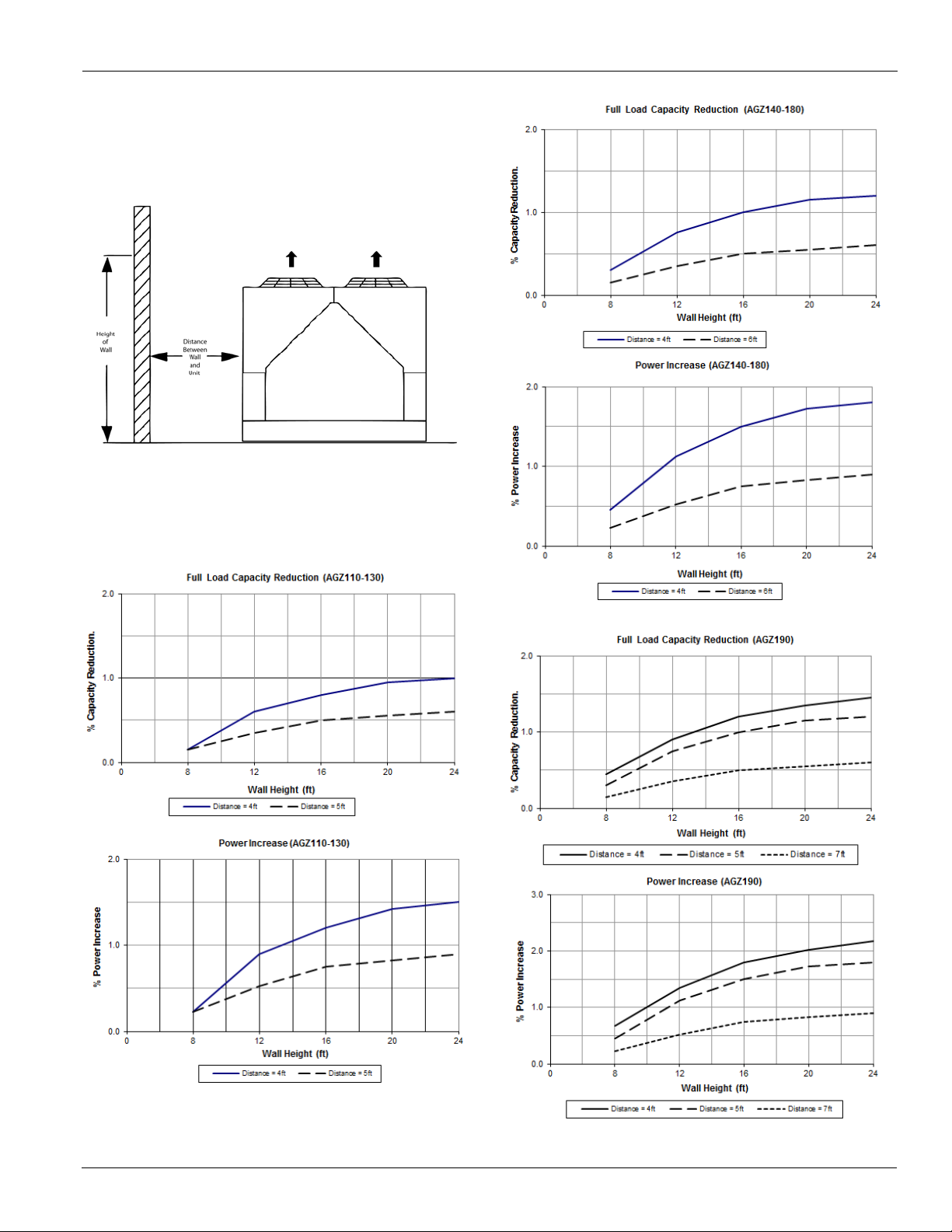
Case 1: Wall on One Side
In this case a solid wall up to 24-feet is considered. (For walls
higher than 24 ft., use the 24-foot values.) Also use these
charts for an adjacent building. For perforated screening walls,
use Case 4. Spacing is differentiated by unit size families.
Figure 3: Wall on One Side of Unit
Note: Maintain a minimum of 4-feet on all sides; except models
140-190, which require 12-feet opposite the control
panel to remove the evaporator.
For models AGZ 075-100: use 4 feet from any height wall. For
models 110-190, use Performance Adjustment curves below.
Figure 4: Case 1 Adjustment Factors (AGZ110D-130D)
Figure 5: Case 1 Adjustment Factors (AGZ140D-180D)
Figure 6: Case 1 Adjustment Factors (AGZ190D)
IM 1165-1 5

Installation and Application Information
Case 2: Two Units, Side-by-Side
Maintain a minimum of 6-feet on all sides; except models 140190, which require 12-feet opposite the control panel to
remove the evaporator.
Figure 7: Case 2 - Two units side by side
For models AGZ 075-100: use 4 feet between units. For
models 110-190, use Performance Adjustment chart in
Figure 8.
Figure 8: Case 2 Adjustment Factors
Case 3: Three or More Units, Side-by-Side
Maintain a minimum of 6-feet on all sides; except models 140190, which require 12-feet opposite the control panel to
remove the evaporator. For more than three units, allow an
additional 2-feet clearance between units.
Figure 9: Case 3 - 3 units side by side
Data is for the middle unit - with a unit on each side. See Case
2, page 6 for Adjustment Factors for the two outside units.
Figure 10: Case 3 Adjustment Factors
6 IM 1165-1
Installation and Application Information
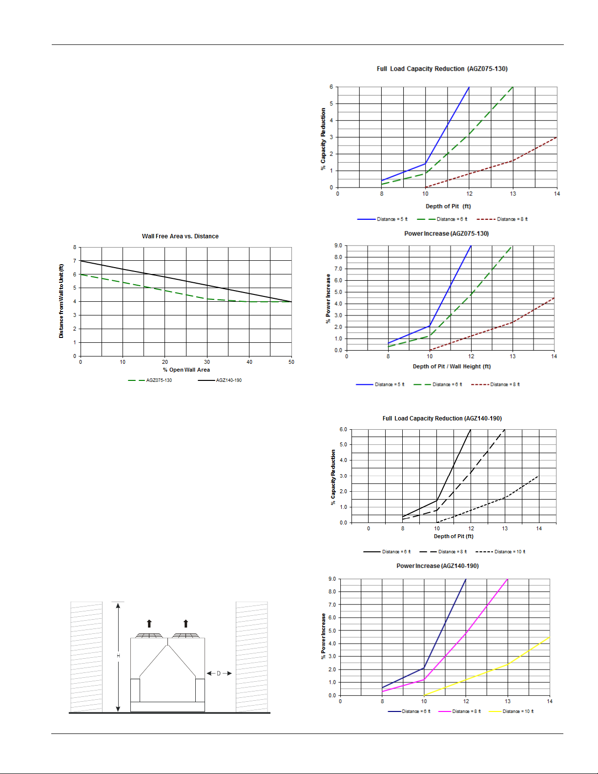
Case 4: Open Screening Walls
Decorative screening walls are often used to help conceal a
unit either on grade or on a rooftop. Design these walls such
that the combination of their open area and distance from the
unit do not require performance adjustment. It is assumed that
the wall height is equal to or less than the unit height when
mounted on its base support. If the wall height is greater than
the unit height, see Case 5, Pit Installation. The distance from
the sides of the unit to the side walls must be sufficient for
service, such as opening control panel doors. For uneven wall
spacing, the distance from the unit to each wall can be
averaged providing no distance is less than 4 feet. Values are
based on walls on all four-sides.
Figure 11: Case 4 Adjustment Factor
Figure 13: Case 5 Adjustment Factors (AGZ075D-130D)
Case 5: Pit Installation
Figure 14: Case 5 Adjustment Factors (AGZ140D-190D)
Pit installations can cause operating problems from air
recirculation and restriction, and require care that sufficient air
clearance is provided, safety requirements are met and service
access is provided. Pit covers must have abundant open area at
least equal to the chiller footprint. A solid wall surrounding a
unit is essentially a pit and this data should be used.
Steel grating is sometimes used to cover a pit to prevent
accidental falls or trips into the pit. The grating material and
installation design must be strong enough to prevent such
accidents, yet provide abundant open area to avoid
recirculation problems. Have any pit installation reviewed by
the Daikin Applied sales representative prior to installation to
ensure it has sufficient air-flow characteristics, and approved
by the installation design engineer to avoid risk of accident.
Figure 12: Case 5 - Pit Installation
IM 1165-1 7

Installation and Application Information
Chilled Water Piping
CAUTION
To prevent damage to the evaporator and potential chiller
failure, a supply strainer is required in the inlet water piping
which connects to this evaporator. This strainer must be
installed prior to operation of the chilled liquid pumps.
Field installed water piping to the chiller must include:
• A cleanable strainer installed at the water inlet to the
evaporator to remove debris and impurities before they
reach the evaporator. Install cleanable strainer within 5
feet (1500 mm) of pipe length from the evaporator inlet
connection and downstream of any welded connections
(no welded connections between strainer and evaporator). See Inlet Strainer Guidelines for more information
including required perforation size.
• A water flow switch must be installed in the horizontal
piping of the supply (evaporator outlet) water line to
avoid evaporator freeze-up under low or no flow conditions. The flow switch may be ordered as a factoryinstalled option, a field-installed kit, or may be supplied
and installed in the field. See page 11 for more informa-
tion.
• Piping for units with brazed-plate evaporators must have
a drain and vent connection provided in the bottom of
the lower connection pipe and to the top of the upper
connection pipe respectively, see Figure 16. These evaporators do not have drain or vent connections due to their
construction. Shell-and-tube evaporators have a drain
located on the bottom of the evaporator. They are
drained of water in the factory and shipped with evaporator drain plugs removed, stored in the control panel or
with an open ball valve in the drain holes. Be sure to
replace plugs or close the valves prior to filling the shelland-tube evaporator with fluid.
• Purge air from the water system before unit start-up to
provide adequate flow through the evaporator.
• Adequate piping support, independent from the unit, to
eliminate weight and strain on the fittings and connections.
• Method to read temperatures and pressures entering and
leaving the evaporator for service and performance verifications.
It is recommended
chiller include:
• Thermometers at the inlet and outlet connections of the
evaporator.
that the field installed water piping to the
• Water pressure gauge connection taps and gauges at the
inlet and outlet connections of the evaporator for measuring water pressure drop.
• Shutoff valves are necessary to isolate the unit from the
piping during unit servicing.
• Minimum bends and changes in elevation to minimize
pressure drop.
• An expansion tank or regulating valve to maintain adequate water pressure
• Vibration eliminators in both the supply and return water
lines to reduce transmissions to the building, required
when the unit is mounted on spring isolators.
• Flush the system water piping thoroughly before making
connections to the unit evaporator.
• Piping insulation, including a vapor barrier, helps prevent condensation and reduces heat loss.
• Regular water analysis and chemical water treatment for
the evaporator loop is recommended immediately at
equipment start-up.
Inlet Strainer Guidelines
An inlet water strainer kit must be installed in the chilled water
piping before the evaporator inlet. A few paths are available to
meet this requirement:
1 A field-installed kit shipped-loose with the unit is
available for all unit sizes and consists of:
• Y-type area strainer with 304 stainless steel perforated
basket, Victaulic pipe connections and strainer cap.
• Extension pipe with (2) Schrader fittings that can be
used for a pressure gauge and thermal dispersion flow
switch. The pipe provides sufficient clearance from the
evaporator for strainer basket removal.
• ½-inch blowdown valve
• Two grooved clamps
The strainer is sized per Tab le 2 and with the pressure drop
shown in the Strainer Pressure Drop graph. Connection sizes
are given in the Dimensions and Weights section on page 21.
2 A field-supplied strainer that meets specification and
installation requirements of this manual.
Table 2: Strainer Data
AGZ-D Model
075-130 3.0 (76) 0.063 (1.6)
140-190 8.0 (203) 0.125 (3.175)
Strainer Size
in. (mm)
Minimum perforation size
in. (mm)
8 IM 1165-1

Installation and Application Information
Air
Vent
Flow
Switch
Vibration
Eliminators
Drain
Outlet
Inlet
P
Isolation
Valves
Strainer
LEAVING FLUID
TEMP. SENSOR
VENT
3/8” PIPE PLUG
VIBRATION
ELIMINATOR
FLOW
SWITCH
GATE
VALV E
FLOW
FLOW
GATE
VALV E
OUTLET
DRAIN
BALANCING
VALV E
VIBRATION
ELIMINATOR
WATER
STRAINER
VALVED
PRESSURE
GAUGE
PROTECT ALL FIELD PIPING
AGAINST FREEZING
INLET
Figure 15: Strainer Pressure Drop
Water Flow Limitations
Constant Evaporator Flow
The evaporator flow rates and pressure drops shown on page
page 44 are for full load design purposes. The maximum flow
rate and pressure drop are based on a 6°F temperature drop.
Avoid higher flow rates with resulting lower temperature drops
to prevent potential control problems resulting from very small
control bands and limited start up/shut off temperature
changes.
The minimum flow and pressure drop is based on a full load
evaporator temperature drop of 16°F. Evaporator flow rates
below the minimum values can result in laminar flow causing
freeze-up problems, scaling and poor control. Flow rates above
the maximum values will result in unacceptable pressure drops
and can cause excessive erosion, potentially leading to failure.
Variable Evaporator Flow
Reducing evaporator flow in proportion to load can reduce
system power consumption. The rate of flow change should be
a maximum of 10 percent of the flow per minute. For example,
if the maximum design flow is 200 gpm and it will be reduced
to a flow of 140 gpm, the change in flow is 60 gpm. Ten
percent of 200 gpm equals 20 gpm change per minute, or a
minimum of three minutes to go from maximum to minimum.
Do not reduce flow lower than the minimum flows listed in the
evaporator pressure drop section, page 44. The water flow
through the evaporator must remain between the minimum and
maximum values listed on page 44. If flow drops below the
minimum allowable, large reductions in heat transfer can
occur. If the flow exceeds the maximum rate, excessive
pressure drop and tube erosion can occur.
Figure 16: Typical Piping, Brazed-Plate Evaporator (models AGZ075D-130D)
Figure 17: Typical Piping, Shell and Tube Evaporator (models AGZ140D-190D)
IM 1165-1 9

Installation and Application Information
System Water Volume Considerations
All chilled water systems need adequate time to recognize a
load change, respond to that load change and stabilize, without
undesirable short cycling of the compressors or loss of control.
In air conditioning systems, the potential for short cycling
usually exists when the building load falls below the minimum
chiller plant capacity or on close-coupled systems with very
small water volumes. Some of the things the designer should
consider when looking at water volume are the minimum
cooling load, the minimum chiller plant capacity during the
low load period and the desired cycle time for the
compressors. Assuming that there are no sudden load changes
and that the chiller plant has reasonable turndown, a rule of
thumb of "gallons of water volume equal to two to three times
the chilled water gpm flow rate" is often used. A storage tank
may have to be added to the system.
BAS should enable chiller only when there is a cooling
demand.
Evaporator Freeze Protection
Evaporator freeze-up can be a concern in the application of aircooled water chillers. To protect against freeze-up, insulation
and electric heaters are furnished with the unit. Models 140
through 190 have immersion heaters with a thermostat; models
075 through 130 have an external plate heater and thermostat.
They protect the evaporator down to -20°F (-29°C) ambient air
temperature; however, see Chilled Water Pump section for
more information. Although the evaporator is equipped with
freeze protection, it does not protect water piping external to
the unit or the evaporator itself if there is a power failure or
heater cable burnout, or if the chiller is unable to control the
chilled water pumps. Use one of the following
recommendations for additional protection:
1 If the unit will not be operated during the winter, drain
evaporator and chilled water piping and flush with
glycol. Drain and vent connections are provided on the
evaporator to ease draining.
2 Add a glycol solution to the chilled water system to
provide freeze protection. Freeze point should be
approximately 10
temperature.
3 The addition of thermostatically controlled heat and
insulation to exposed piping.
The evaporator heater cable is factory wired to the 115 volt
circuit in the control box. This power should be supplied from
a separate source, but it can be supplied from the control
circuit. Operation of the heaters is automatic through the
ambient sensing thermostat that energizes the evaporator
heaters for protection against freeze-up. Unless the evaporator
is drained in the winter or contains an adequate concentration
ºF below minimum design ambient
of anti-freeze, the disconnect switch to the evaporator heater
must not be open.
Chilled Water Pump
It is important that the chilled water pumps be wired to, and
controlled by, the chiller's microprocessor. When equipped
with optional dual pump output, the chiller controller has the
capability to selectively send the signal to a pump relay (by
others) to start pump A or B or automatically alternate pump
selection and also has standby operation capability. The
controller will energize the pump whenever at least one circuit
on the chiller is enabled to run, whether there is a call for
cooling or not. This helps ensure proper unit start-up sequence.
The pump will also be turned on when the water temperature
goes below the Freeze Setpoint for longer than a specified time
to help prevent evaporator freeze-up. Connection points are
shown in the Field Wiring Diagram on page 46.
CAUTION
Adding glycol or draining the system is the recommended method of
freeze protection. If the chiller does not have the ability to control the
pumps and the water system is not drained in temperatures below
freezing, catastrophic evaporator failure may occur.
Failure to allow pump control by the chiller may cause the
following problems:
1 If any device other than the chiller attempts to start the
chiller without first starting the pump, the chiller will
lock out on the No Flow alarm and require manual reset.
2 If the chiller evaporator water temperature drops below
the “Freeze setpoint” the chiller will attempt to start the
water pumps to avoid evaporator freeze. If the chiller
does not have the ability to start the pumps, the chiller
will alarm due to lack of water flow.
3 If the chiller does not have the ability to control the
pumps and the water system is not to be drained in
temperatures below freezing, the chiller may be subject
to catastrophic evaporator failure due to freezing. The
freeze rating of the evaporator is based on the immersion
heater and pump operation. The immersion heater itself
may not be able to properly protect the evaporator from
freezing without circulation of water.
Low Ambient Operation
Compressor staging is adaptively determined by system load,
ambient air temperature, and other inputs to the MicroTech III
control. A low ambient option with fan VFD allows operation
down to -10° F (-23° C). The minimum ambient temperature is
based on still conditions where the wind is not greater than
five mph. Greater wind velocities will result in reduced
discharge pressure, increasing the minimum operating ambient
temperature.
10 IM 1165-1

Installation and Application Information
FactorCorrectionFlow
T
CapacitykW
×
(l/s) Flow Glycol
High Ambient Operation
AGZ-D units for high ambient operation (105ºF to 125ºF,
40.1ºC to 51.7ºC) require the addition of the optional high
ambient package that includes a small fan with a filter in the
air intake to cool the control panel.
All units with the optional VFD low ambient fan control
automatically include the high ambient option.
Flow Switch
All chillers require a chilled water flow switch to check that
there is adequate water flow through the evaporator and to shut
the unit down if there isn't. There are two options for meeting
this requirement.
1 A factory-mounted thermal dispersion flow switch.
2 A "paddle" type flow switch is available from Daikin
Applied for field mounting and wiring. Wire from switch
terminals Y and R to the unit control panel terminals
shown on the field wiring diagrams, beginning on
page 46. Mount the flow switch in the leaving water line
to shut down the unit when water flow is interrupted. A
flow switch is an equipment protection control and
should never be used to cycle a unit.
Installation should be per manufacturer's instructions included
with the switch . Flow switches should be calibrated to shut off
the unit when operated below the minimum listed flow rate for
the unit as listed on page 44.
There is also a set of normally closed contacts on the switch
that can be used for an indicator light or an alarm to indicate
when a "no flow" condition exists. Freeze protect any flow
switch that is installed outdoors. Differential pressure switches
are not recommended for outdoor installation. They can freeze
and not indicate a no-flow conditions.
Grooved Coupling/Flow Switch Warning
On units with shell-and-tube vessels and with factory-mounted
flow switches and where flange connections (grooved-toflange adaptors or weld-on flanges) are to be used, relocating
the flow switch is required to allow for possible future
replacement. The flange will interfere with unscrewing the
switch. The following procedure is recommended before
installing a flange to avoid interference:
Glycol Solutions
The use of a glycol/water mixture in the evaporator to prevent
freezing will reduce system capacity and efficiency, as well as
increase pressure drop. The system capacity, required glycol
solution flow rate, and pressure drop with glycol may be
calculated using the following formulas and tables.
Delta
−×=18.4
1 Capacity - Multiply the capacity based on water by the
Capacity correction factor from Tab le 3 to Table 6.
2 Flow - Multiply the water evaporator flow by the Flow
correction factor from Table 3 to Ta ble 6 to determine
the increased evaporator flow due to glycol. If the flow is
unknown, it can be calculated from the following
equation:
3 Pressure drop - Multiply the water pressure drop from
Tabl e 2 7 by Pressure Drop correction factor from Tabl e 3
to Table 6. High concentrations of propylene glycol at
low temperatures may cause unacceptably high pressure
drops.
4 Power - Multiply the water system power by Power
correction factor from Tabl e 3 to Table 6.
Test coolant with a clean, accurate glycol solution hydrometer
(similar to that found in service stations) or refractometer to
determine the freezing point. Obtain percent glycol from the
freezing point table below. It is recommended that a minimum
of 25% solution by weight be used for protection against
corrosion or that additional compatible inhibitors be added.
Concentrations above 35% do not provide any additional burst
protection and should be carefully considered before using.
CAUTION
Do not use an automotive-grade antifreeze. Industrial grade
glycols must be used. Automotive antifreeze contains
inhibitors which will cause plating on the copper tubes within
the chiller evaporator. The type and handling of glycol used
must be consistent with local codes.
1.Remove the flow switch and plug the switch opening in the
nozzle.
2.Install the grooved-to-flange adaptor or weld on flange.
3.Relocate the flow switch in the water piping outside the
flange, close enough to it that the wire leads will reach and the
switch can still be unscrewed.
IM 1165-1 11
Installation and Application Information
!
Table 3: Ethylene Glycol Factors-Brazed Plate Evaporator
% E.G.
10 26 -3.3 0.998 0.998 1.036 1.097
20 18 -7.8 0.993 0.997 1.060 1.226
30 7 -13.9 0.987 0.995 1.092 1.369
40 -7 -21.7 0.980 0.992 1.132 1.557
50 -28 -33.3 0.973 0.991 1.182 1.791
Freeze Point
o
o
F
Capacity Power Flow PD
C
Table 4: Propylene Glycol Factors-Brazed Plate Evaporator
% P.G.
10 26 -3.3 0.995 0.997 1.016 1.100
20 19 -7.2 0.987 0.995 1.032 1.211
30 9 -12.8 0.978 0.992 1.057 1.380
40 -5 -20.6 0.964 0.987 1.092 1.703
50 -27 -32.8 0.952 0.983 1.140 2.251
Freeze Point
o
o
F
Capacity Power Flow PD
C
Table 5: Ethylene Glycol Factors-Shell & Tube Evaporator
% E.G.
10 26 -3.3 0.996 0.997 1.036 1.097
20 18 -7.8 0.988 0.994 1.061 1.219
30 7 -13.9 0.979 0.991 1.092 1.352
40 -7 -21.7 0.969 0.986 1.132 1.532
50 -28 -33.3 0.958 0.981 1.182 1.748
Freeze Point
o
o
F
Capacity Power Flow PD
C
Table 6: Propylene Glycol Factors-Shell & Tube Evaporator
% P.G.
10 26 -3.3 0.991 0.996 1.016 1.092
20 19 -7.2 0.981 0.991 1.032 1.195
30 9 -12.8 0.966 0.985 1.056 1.345
40 -5 -20.6 0.947 0.977 1.092 1.544
50 -27 -32.8 0.932 0.969 1.140 1.906
Freeze Point
o
o
F
Capacity Power Flow PD
C
POE Lubricants
WARNING
POE oil must be handled carefully using proper protective
equipment (gloves, eye protection, etc.) The oil must not
come in contact with certain polymers (e.g. PVC), as it may
absorb moisture from this material. Also, do not use oil or
refrigerant additives in the system.
POE type oil is used for compressor lubrication. This type of
oil is extremely hydroscopic which means it will quickly
absorb moisture if exposed to air and may form acids that can
be harmful to the chiller. Avoid prolonged exposure of POE oil
to the atmosphere to prevent this problem. For more details on
acceptable oil types, contact your Daikin Applied service
representative.
It is important that only the manufacturer’s recommended oils
be used. Acceptable POE oil types are:
• CPI/Lubrizol Emkarate RL32-3 MAF
• Copeland Ultra 32-3 MAF
• Parker Emkarate RL32-3MAF
• Virginia LE323MAF
• Nu Calgon 4314-66
12 IM 1165-1

Remote Evaporators
SO FIELD MUST USE MIN 45% SILVER BRAZE ROD.
BRAZE CONNECTIONS ON EVAP ARE STAINLESS STEEL,
CIR. #2
LIQUID
CIR. #1
LIQUID
TEMP SENSOR
LOCATION
CIR. #2
SUCTION
CIR. #1
SUCTION
ENTERING WATER
STAINLESS STEEL
PIPE PLUG
Remote Evaporators
Piping and Application
AGZ-D units have two circuits, each with either two or three
compressors. These circuits must be kept separated throughout
the entire refrigerant piping system. Pipe all lines (suction,
liquid and hot gas bypass, if used) of each evaporator circuit to
a circuit on the outdoor unit. Be careful not to cross-pipe lines.
Evaporator circuit #1 must be piped to the circuit #1
condensing unit . Evaporator circuit #2 must be piped to the
circuit #2 condensing unit.
CAUTION
Refrigerant circuits must be kept isolated from eather
throughout the entire system. For braze plateevaporators, note
that the Circuit #1 Suction Line is located diagonally from
Circuit #1 Liquid Line, and the same for Circuit #2 Liquid and
Suction Lines. See Figure 18.
Figure 18: Location of Connections
The primary concerns related to piping are refrigerant pressure
drop; a solid liquid feed to the expansion valves, continuous
oil return and properly sized refrigerant specialties.
AGZ-D Unit Performance is negatively affected by Suction
Line Pressure Drop Losses. Distance between the AGZ-D unit
and the Remote Evaporator should be kept as short as possible
to minimize the performance derate.
Table 7: Remote Evaporator Piping Limitations
Maximum measured piping distance between the
unit and the remote evaporator
Maximum equivalent Feet of Distance between
the unit and evaporator including elbows and traps
Note: For Installations with Distances exceeding these values Daikin
Applied Technical Responce Center (TRC) must be consulted for
approval of the piping design for factory warranty to be valid
90 ft.
150 ft.
Refrigerant piping is permitted to be installed below ground
provided the following conditions are met:
• Piping or pipe insulation is NOT in contact with the
ground
• Piping is installed in an open or enclosed chase that
allows for inspection and leak testing
• Piping is sized and installed per ASHRAE guidelines
Piping Recommendations
IMPORTANT: Refrigerant piping design must be provided by
a qualified Architect or Systems HVAC Design Engineer
familiar with piping design, as well as local codes and
regulations. The manufacturer recommendations provided here
are to be used as a general guide, but do not replace system
design by a qualified professional. All field piping, wiring, and
procedures must be performed in accordance with ASHRAE,
EPA, local codes, and industry standards.
Proper refrigerant piping can make the difference between a
reliable system and an inefficient, problematic system. See the
recommended field pipe sizes shown in Table 8 and Tabl e 1 0.
For additional information about refrigerant piping techniques
and sizing, see the Daikin Refrigerant Piping Design Guide,
AG 31-011, which can be found on www.DaikinApplied.com.
IM 1165-1 13
WARNING
Improper installation can cause refrigerant migration, flood
back, oil loss, line corrosion, or mechanical failures.
For Installations where the evaporator is installed either above
or below the unit - the following recommendations apply:
Evaporator installed below outdoor unit:
• 30 ft. Maximum Vertical Distance
• Only single riser suction tubing is to be used - Double riser
installations are not permitted
• A suction line trap must be installed at the bottom of the
riser and a second trap at 20 ft. height
Evaporator installed above the AGZ-D Outdoor unit:
• 30 ft. Vertical Distance is the recommended maximum to
prevent loss of liquid subcooling
Installation Guidelines
Insulate the suction line to reduce excessive superheat buildup. Insulate the liquid line, where located in areas above
ambient temperature, to prevent loss of subcooling and
consequent liquid flashing.
The installer must leak test the remote piping with nitrogen at
150 psig maximum pressure, then properly evacuate the piping
systemto 500 microns or below and provide the operating
charge of R-410A. A holding charge of nitrogen/helium is

Remote Evaporators
Unit Model Nom inal Tubing Re commended Suction Line Sizes, OD Copper -based on Eq. ft. Length Max. Suct.
AGZ-DB Tons Per Conn. Riser Line Size
(Rem ote Evap) Circuit Size for Vertical
At Unit Size
F
Size
F
Size
F
Siz e
F
Size
F
Up flo w t o Co m pr .
AGZ075DB
36 2 5/8
2 1/8 0.5 2 1/8 0.8 2 1/8 1.1 2 1/8 1.4 2 1/8 1.6
2 1/8
AGZ080DB
40 2 5/8
2 1/8 0.7 2 1/8 1.0 2 1/8 1.3 2 1/8 1.7 2 1/8 2.0
2 1/8
AGZ090DB
45 2 5/8
2 1/8 0.8 2 1/8 1.2 2 1/8 1.6 2 1/8 2.1 2 1/8 2.5
2 1/8
AGZ100DB
50 2 5/8
2 1/8 1.0 2 1/8 1.5 2 1/8 2.0 2 1/8 2.5 2 1/8 3.0
2 1/8
AGZ110DB
53 2 5/8
2 1/8 1.1 2 1/8 1.7 2 5/8 0.8 2 5/8 1.0 2 5/8 1.2
2 1/8
AGZ125DB
58 2 5/8
2 1/8 1.3 2 1/8 1.9 2 5/8 0.9 2 5/8 1.2 2 5/8 1.4
2 1/8
AGZ130DB
65 2 5/8
2 1/8 1.6 2 5/8 0.9 2 5/8 1.1 2 5/8 1.4 2 5/8 1.7
2 5/8
AGZ140DB
68 2 5/8
2 1/8 1.7 2 5/8 0.9 2 5/8 1.2 2 5/8 1.6 2 5/8 1.9
2 5/8
AGZ160DB
76 2 5/8
2 5/8 0.8 2 5/8 1.1 2 5/8 1.5 2 5/8 1.9 3 1/8 1.0
2 5/8
AGZ180DB
86 2 5/8
2 5/8 1.0 2 5/8 1.4 2 5/8 1.9 2 5/8 2.4 3 1/8 1.2
2 5/8
AGZ190DB
90 2 5/8
2 5/8 1.0 2 5/8 1.5 2 5/8 2.1 2 5/8 2.6 3 1/8 1.3
2 5/8
No te s :
1. PD °F is Press ure Dro p sho wn in degrees F. M ultiply by 2.25 for ps i. Exam ple: 1°F pres sure dro p = 2.2 5 psi.
2. Fo r equivalent lengt hs between t he table values , use t he colum n higher than t he length and calc ulate the pres sure dro p based o n the direct ratio
o f the lengt h com pared to the co lumn value. Example: Fo r 90 ft equivalent leng th, use the c olumn v alue fo r 100 ft t imes 90/ 100 fo r the press ure drop
3. No minal to ns fo r mo dels 80, 125, and 160 units are averaged per c ircuit.
Up to
50 Equiv. Ft 75 Equiv. Ft 100 Equiv. Ft 125 Equiv. Ft 150 Equiv. Ft
Up to Up to Up to Up to
provided for the outdoor section. The brazed-plate evaporators
on Models 075 to 130 have no charge and are not sealed. The
shell-and-tube evaporators on Models 140 to 190 have a
nitrogen holding charge. Holding charges must be removed
prior to the R-410a charging procedure.
The use of double risers for vertical gas risers is not allowed.
Size the vertical riser per Tabl e 8 . Follow ASHRAE
procedures.
Slope the refrigerant lines 1" per 10 feet of horizontal run in
the direction of refrigerant flow to assist oil return.
Avoid using hot gas bypass (or provide condenser fan VFDs)
for applications when operation in ambient temperature below
40ºF is expected. This is necessary to maintain adequate
condensing pressures and liquid refrigerant at the expansion
valve when condenser capacities are at their maximum.
Interconnecting refrigerant piping and total system refrigerant
charge are field supplied and installed. The outdoor unit and
remote evaporator are shipped with a nitrogen holding charge
that must be removed and replaced with R 410A.
Pressure drops in the refrigerant lines should be maintained at
the equivalent feet calculation shown in Tab le 8 and should not
exceed 3°F and line lengths should be made as short as
possible. Follow ASHRAE recommendations. Exceeding these
recommendations will decrease performance and could impact
reliability.
Use caution in sizing the liquid line in applications where the
evaporator is above the outdoor section. The weight of the
liquid refrigerant in the vertical column will decrease the
pressure at the top of the riser (0.43 psi per foot of vertical
rise) allowing some of the refrigerant to flash to a gas.
Adequate refrigerant subcooling is needed at the expansion
valve for proper operation.
Care should be taken while designing piping system to avoid
the draining of condensed refrigerant to the lower component
when normal shutdown procedures do not occur (such as a
power failure).
Location of Liquid Line Filter Drier, Solenoid Valve and
Expansion Valve
These components must be installed adjacent to the Remote
evaporator. The expansion valves must be installed within 12
inches of the Evaporator Inlet Connection and the outlet piping
of the Expansion valve must go directly into the Evaporator
with no bends in between.
The Liquid line Solenoid valves must be installed within 3 ft.
of the evaporator. The Liquid line Solenoid Valve must be
connected to the AGZ cable using a junction box to extend the
wiring to the length required to reach the solenoid.
The Liquid line Filter Drier must be installed at the Remote
Evaporator - upstream of the Liquid Solenoid Valve and
Expansion Valve
A small trap must be provided at the base of each major
vertical gas riser to assist in the collection of oil. If vertical
risers exceed more than 20 feet, install a small trap at the
midpoint and at a maximum of 20 foot intervals.
How to determine performance derate:
Using the model size and the equivalent feet of piping between
the unit and the evaporator, find the Pressure Drop in °F from
Tabl e 8 . Cross-reference the Pressure Drop in °F to Tab le 9 to
find the capacity, power, and EER derate factor.
Table 8: Recommended Horizontal or Downflow Suction Line Size, R-410A
PD
°
14 IM 1165-1
PD
°
PD
°
PD
°
PD
°

Table 9: Performance Derate Factors for Suction Line Pressue Drop
Suction Line Unit Unit
Press. Drop Capacity Power
°F % %
0°F 100.0 100.0
1.0°F 98.5 99.5
2.0°F 97.1 98.9
3.0°F 95.6 98.4
4.0°F 94.1 97.9
5.0°F 92.6 97.4
No te: Data at AH RI Standard Chiller Rat ing Condit ion o f 54.0 F/ 44.0 F
Chiller Inlet and Outlet Wat er Temps and 95.0 F Outdo or A ir Temperature.
Unit
EER
100.0
99
%
98.2
97.2
96.1
95.1
Unit Model Nominal Tubing Re comme nded Liquid Line Sizes, OD Copper
AGZ-DB Tons Conn.
(Remote Evap) Per Size
Circuit At Unit Size
Size
Size
Size
Size
AGZ075DB
36
1 1/8 1 1/8 0.3 1 1/8 0.5 1 1/8 0.6 1 1/8 0.8 1 1/8 1.0
AGZ080DB
40
1 1/8 1 1/8 0.4 1 1/8 0.6 1 1/8 0.8 1 1/8 1.0 1 1/8 1.2
AGZ090DB
45
1 1/8 1 1/8 0.5 1 1/8 0.7 1 1/8 1.0 1 1/8 1.2 1 1/8 1.5
AGZ100DB
50
1 1/8 1 1/8 0.6 1 1/8 0.9 1 1/8 1.2 1 1/8 1.5 1 1/8 1.8
AGZ110DB
53
1 1/8 1 1/8 0.7 1 1/8 1.0 1 1/8 1.3 1 1/8 1.6 1 1/8 2.0
AGZ125DB
58
1 1/8 1 1/8 0.8 1 1/8 1.1 1 1/8 1.5 1 1/8 1.9 1 1/8 2.3
AGZ130DB
65
1 1/8 1 1/8 0.9 1 1/8 1.4 1 1/8 1.9 1 1/8 2.3 1 1/8 2.8
AGZ140DB
68
1 3/8 1 3/8 0.4 1 3/8 0.6 1 3/8 0.8 1 3/8 0.9 1 3/8 1.1
AGZ160DB
76
1 3/8 1 3/8 0.5 1 3/8 0.7 1 3/8 0.9 1 3/8 1.1 1 3/8 1.4
AGZ180DB
86
1 3/8 1 3/8 0.6 1 3/8 0.9 1 3/8 1.1 1 3/8 1.4 1 3/8 1.7
AGZ190DB
90
1 3/8 1 3/8 0.6 1 3/8 0.9 1 3/8 1.2 1 3/8 1.6 1 3/8 1.9
Note s :
1. PD°F is P ressure Drop s hown in degrees F. M ultiply by 4.75 for psi. Exam ple: 1 F degree pressure drop = 4.75 ps i.
2. For equiv alent lengths between the table values, use the co lumn higher than the length and calc ulate the press ure drop based on t he direct ratio
o f the length co mpared to the co lumn value. Example: For 90 f t equivalent length, use the c olumn v alue fo r 100 ft tim es 90/100 for the pressure dro p
3. Nominal to ns fo r models 80, 125, and 160 units are averaged per circuit.
150 Equiv. Ft
Up to
50 Equiv. Ft 75 Equ iv. Ft 100 Equiv. Ft 125 Equiv. Ft
Up to Up to Up to Up to
Table 10: Recommended Liquid Line Size, R-410A
Remote Evaporators
PD°F
Wiring for AGZ-Remote Evaporators
Refrigerant Specialties Kit
Remote Evaporator units include a Refrigerant Specialties Kit
which supplies the following field-installed components:
• Charging valves
• Expansion valves
• Models 075-130 use Thermal Expansion Valves (TXV),
EXV is option
• Models 140-190 use Electronic Expansion Valves (EXV)
and includes M12 cable
• Liquid line solenoid valves and cable
• Liquid line filter driers with filter drier core, clamp, and felt
• Liquid line sight glasses (and saddle adapter for AGZ140-
• Ball valves
• Suction temperature sensor tubes
• Schrader fittings and Schrader core for suction transducers
gasket
190D)
IM 1165-1 15
PD°F
PD°F
Sensor Wiring
The Remote Evaporator AGZ-D Units come with long sensor
wires for the remote evap installation. These wires allow the
evaporator to be installed up to 90 ft. from the AGZ-D unit
without splicing these wires. The sensor wires to the
evaporator include the following :
• Evaporator Water Inlet and Outlet Temperature Sensor
• Suction Line Temperature Sensors for Piping at the
Evaporator for both Circuit #1 and #2
• Suction Transducer Wiring for Installation on Evaporator
Suction Piping for both Circuit #1 and #2
For AGZ140-190D units with Electric Expansion Valves, the
wiring to the evaporator must be spliced using #14 wire gauge
shielded wire.
The factory supplied cable with #18 ga wire is suitable for 30
ft. maximum length. For installations where the evaporator
will be located more than 30 ft from the outdoor unit, the
sensors must be relocated to the Suction Line piping at the
Evaporator for proper unit operation. If the evaporator is
located within 30 linear feet of piping from the outdoor unit,
the two suction temperature sensors can be left on the outdoor
PD°F
PD°F

Remote Evaporators
ADDRESS=3
T1 T3
T2
T4
E.E.X.V.1
123456
ON
ADDRESS=5
T1 T3
T2
T4
E.E.X.V.2
123456
ON
BRN
WHT
BLU
BLK
RED
GRN
WHT
BLK
RED
GRN
WHT
BLK
BLU
BLK
WHT
BRN
M16
902
900
M26
906
901
POL94E.00/MCQ
D01A
C1
D01B
DI1
R1
T3-M
X3
+5V
X1
T3-M
X2
M1-
M2+
M2-
M1+
+24V
24VGNDB-A+
A+ B-
GND
24V
POL94E.00/MCQ
D01A
C1
D01B
DI1
R1
T3-M
X3
+5V
X1
T3-M
X2
M1-
M2+
M2-
M1+
+24V
24VGNDB-A+
A+ B-
GND
24V
W1
W1
W2
W2
EXV-1
1
2
3
4
GTB5
W1
W1
W2
W2
EXV-2
1
2
3
4
GTB5
A2 A1
M16
(438)
(439)
(440)
NC
NO
903
A2 A1
M26
(538)
(539)
(540)
NC
NO
907
(847) (847) (847) (847)
(848) (848) (848) (848)
(863) (863) (863) (863)
/(756)
/(659)
/(756)
/(659)
unit factory suction line as shipped only if TXVs are used.
EXVs require sensors be located at the evaporator.
There are two evaporator water temperature sensors with 90
feet of cable coiled in the unit behind the control panel for
extension to the evaporator and insertion in fitting located on
the inlet and outlet nozzle on AGZ-D models 140 to 190. For
models AGZ 075 to 130 with brazed-plate evaporators, the
sensors are inserted into back of heat exchanger, opposite the
water connections, at the designated inlet and outlet water
temperature sensor locations.
There is one suction line refrigerant temperature sensor per
circuit installed on suction line with 90 feet of cable coiled
behind the unit control panel, intended for extension to the
evaporator. Place the sensor in a brazed well (provided in kit,
installed in the field) on the suction line in a straight-flat area,
close to the suction line pressure transducer. Install with heat
conductive compound and insulate well. If installed on a
horizontal pipe run, locate between the 2-4 o'clock positions,
or, on a TXV, locate the bulb and equalizer line on suction line
at the 3 or 9 o’clock position.
There is one suction line pressure transducer per circuit with
90 feet of cable coiled, installed on the suction line behind the
unit control panel for extension to the evaporator. Mount the
transducer in the suction line, 1-2 feet from the evaporator
head, on the top or side of the pipe. Connection is ¼-inch flare
with a flare Schrader.
40-feet of the evaporator, and up to 60 additional feet of 14GA
shielded wire connected from the cable to the unit, allowing up
to a total distance of 100 feet.
Figure 19: EXV Field Wiring
One solenoid valve per circuit must be wired to the unit
control panel. They come equipped with an 8-foot cable that
must be added to. See the wiring diagram on page 65 for
connection points at unit.
Expansion Valve Wiring
AGZ-D models 075-130 use Thermal Expansion Valves
(TXV standard, EXV optional). These valves must be located
within 12 inches of the evaporator liquid line connections and
the expansion valve bulbs. The 1/4” equalizer lines must be
attached to the suction pipes near the evaporator outlet.
AGZ-D models 140-190 use Electronic Expansion Valves
(EXV). The EXV has a 1 ft. cable attached with an M12
Threaded Connector. A 15 ft. cable is supplied with the kit to
attach to the 1 ft cable at the valve.
The field must supply #14 ga. shielded wires to extend this
cable to run back and connect to the Expansion Valve control
module located inside the AGZ-D control box. When splicing
is required the connections must be soldered together and
individually shrink wrapped to be made water resistant. The
expansion valve wiring cannot run in conduit with other wiring
that is over 24 Volts AC. Shielding must cover the wiring from
the unit to the EXV, including the splice connection.
The electronic expansion valve has a 40-foot long cable
attached and can be used, when the outdoor unit is less than 40
feet away. Beyond that, a junction box must be located within
16 IM 1165-1
Liquid Line Solenoid Valve Wiring
The Liquid Line Solenoid valves are supplied as part of the
Specialties Kit. These valves must be located within 3 feet of
the evaporator. Included with the Liquid Line Solenoids are
wiring cables which are 10 ft. long. These cables must be
connected to the termfinal block inside the AGZ-D control box
via a field-supplied junction box and #14 ga. wiring. This
24volt wiring should be run in conduit, or at a minimum, twowire cable with a protective covering must be used. See Field
Wiring Diagram included in unit, or Typical Field Wiring
Diagram on page 46 and page 47 for wiring schematic.
Pumpdown
The pumpdown capacity of AGZ units is given in the Physical
Data Tables starting on page 36. Care should be exercised to
include all equipment and lines when calculating the system
charge relative to the unit's pumpdown (storage) capacity. The
AGZ-D remote evaporators have an insignificant operating
charge. It is mandatory that the liquid line solenoid valve be
located close to the evaporator so that pump down does not
have to remove and store a large quantity of liquid refrigerant
from the liquid line.

Figure 20: Remote Evaporator Piping Models 075-130
(FIELD SUPPLIED)
30 FEET FROM THE OUTDOOR UNIT, THEN
THE SUCTION TEMPERATURE SENSORS AND
1. FOR FILTER DRIER SERVICE:
THE EVAPORATOR AS SHOWN.
TRANSDUCERS MUST BE RE-LOCATED AT
(FIELD SUPPLIED)
(INCLUDED IN KIT)
CIR. #2
LIQUID
EXPANSION VALVE (INCLUDED IN KIT)
CIR. #1
LIQUID CIR. #2
LIQUID
CIR. #2
SUCTION
CIR. #1
SUCTION
FILTER DRIER CLAMP
IF EVAPORATOR IS LOCATED MORE THAN
SIGHT GLASS (INCLUDED IN KIT)
LIQUID
CIR. #1
SOLENOID VALVE (INCLUDED IN KIT)
FILTER DRIER SHELL
SCHRADER FITTINGS
NOTES:
ROUTE COPPER TUBE PIPING
APPROXIMATELY AS SHOWN
FELT GASKET KIT
FILTER DRIER CORES
WATER
(FIELD SUPPLIED)
REQUIRED
OUTLET
WATER STRAINER
(ALL INCLUDED IN KIT)
BALL VALVE
SCHRADER FITTINGS (FIELD SUPPLIED)
WATER INLET
2. LIQUID LINE SOLENOID & FILTER DRIER MUST
LINE BALL VALVE LOCATED NEXT TO DRIER.
SO FIELD MUST USE MIN 45% SILVER BRAZE ROD.
BRAZE CONNECTIONS ON EVAP ARE STAINLESS STEEL,
SCHRADER FITTINGS
AGZ075-130D (6-8) FAN UNITS
(6 FAN UNIT SHOWN)
PUMP DOWN SYSTEM USING LIQUID
3. SUPPORT FIELD PIPING AS REQUIRED.
COMPRESSORS
CIRCUIT #1
COMPRESSORS
CIRCUIT #2
OPTIONAL HOTGAS BYPASS LINE MUST ENTER FROM VERTICAL POSITION AS SHOWN
BE LOCATED AT REMOTE EVAP.
CIR. #1
HOTGAS BYPASS
OPTION
BYPASS CIR. #2
OPTION HOTGAS
BLK#2 TO TB2 93
GND TO CONNECT WITH GND WIRE
RUN SOLENOID VALVE CABLE INTO BACK
OF CONTROL BOX AND CONNECT TO:
CIR#1
BLK#1 TO TB2 91
BLK#2 TO TB2 93
GND TO CONNECT WITH GND WIRE
CIR#2
BLK#1 TO TB2 92
SOLENOID VALVE CABLES
(INCLUDED IN KIT)
R331738201 0B
(INCLUDED IN KIT)
PIPE ASSEMBLY
TEMP. SENSOR
LEAVING WATER
LEAVING WATER
VALVE CORE
(INCLUDED IN KIT)
FOR EQUALIZER LINE
CHARGING VALVE
SCHRADER FITTINGS
0.25" DIAMETER HOLE
TO EXPANSION VALVE
(INCLUDED IN KIT)
FOR SUCTION
NEAR EVAPORATOR)
SUCTION
CIR. 2
(INCLUDED IN KIT)
TRANSDUCERS
SUCTION TEMPERATURE
SENSOR TUBE (LOCATED
EXPANSION
VALVE BULB
SUCTION
CIR. 1
CIR. #2
LIQUID
CIR. #1
LIQUID
TEMP SENSOR
LOCATION
CIR. #2
SUCTION
CIR. #1
SUCTION
ENTERING WATER
STAINLESS STEEL
PIPE PLUG
Remote Evaporators
IM 1165-1 17
 Loading...