

Page 1

Replacement Parts List No. 700050800
Revision C 11/2015
Daikin
Trailblazer™
Air-Cooled Scroll Chiller
AGZ
075-180
Vintage E
Unit Revision 00
To nd your Daikin Applied parts distributor, call 1-800-377-2787 or visit www.DaikinApplied.com
Page 2

Contents
Parts List Revision History...................................................................................................................3
Serial Number Nomenclature
Unit Model Nomenclature
Electrical Legend
Unit Controls
Refrigeration Circuit
Compressor Layout Diagrams .....................................................................................................12
Compressors
AGZ 075 ................................................................................................................................13
A GZ 080- 100 .......................................................................................................................14
AGZ 110- 130 .......................................................................................................................15
AGZ 140- 161 .......................................................................................................................16
AGZ 170, 180 .......................................................................................................................17
Evaporator ..................................................................................................................................18
Evaporator Insulation ...................................................................................................................19
Liquid Line Piping ................................................................................................................ 20 - 21
Discharge Line Piping ..................................................................................................................22
Suction Line Piping ......................................................................................................................23
........................................................................................................................... 8 - 9
...............................................................................................................................10 - 11
..............................................................................................................4
.............................................................................................................. 5 - 7
Hot Gas Bypass Piping ................................................................................................................24
Sensor & Transducer Location ............................................................................................ 25 - 26
Miscellaneous Components ........................................................................................................27
Condenser Section
Fan Motor and Fan Deck Diagram ...................................................................................... 28 - 29
Condenser Coils ..........................................................................................................................29
Coil Grilles and Coil Louvers
Base Grilles ............................................................................................................................... 31 - 32
Base Louvers............................................................................................................................. 33 - 34
Optional Equipment
Critical Parts List...........................................................................................................................CPL1
................................................................................................................... 35 - 37
.............................................................................................................30
Air-Cooled Scroll Chiller, AGZ 075-180, Vintage E, Unit Rev. 00 Rev. C 11/15 RPL 7000508 / Page 2
Page 3

Parts List Revision History
Revision Date Description
NEW 3/2015 New
A 6/2015 Page 5-7: Updated Unit Model Nomenclature.
Page 10: Added Control Box Label example.
Page 11: Added new page for common Unit Controls.
Page 16: Added info for Size 161.
Page 17: Removed info for Size 160.
Page 18: Added Water Flow Sensor Adapter.
Page 27: Added Sound Blanket info for Size 161, removed info for Size 160.
Page 34: Corrected part #s for Base Louver Kits, were 334704706, 707, 708.
Page 35: Added Water Flow Sensor Adapter.
CPL1: Added page for Critical Parts List.
B 6/2015 Page 22: Corrected description for 331996402, was "Harness, Discharge Solenoid".
Page 31: Corrected Ref. Bubbles for all sizes..
Page 32: Corrected Qty. for Ref. W61 and removed Ref. W62.
Page 33: Corrected Ref. Bubbles for Sizes 110-130.
Page 34: Corrected Part Numbers and Quantities for all Base Louver-Sides.
C 11/2015 Page 18: Corrected part #s for Ref. 001, was 331598011 for all sizes; and Ref. 002, was
331597903 for all sizes.
Page 26: Updated all Sensors, were 193414602, 03.
Page 29: Added part #s for Condenser Coils.
Page 35: Corrected descriptions for Control Box Exhaust Fan & Control Box Heater Kits,
were High Ambient and Low Ambient Kits. Added HGBP Kit note about T4 Kit.
CPL1: Updated Temp Sensor part #, was 193414602.
Daikin Applied, 13600 Industrial Park Blvd., P.O. Box 1551, Minneapolis, MN 55440 (763) 553-5330
Air-Cooled Scroll Chiller, AGZ 075-180, Vintage E, Unit Rev. 00 Rev. C 11/15 RPL 7000508 / Page 3
Page 4

Serial Number Nomenclature
STN U 13 05 048200
Plant Identication
STN = Staunton, VA
U = Unit
Year of Manufacture
14 = 2014
15 = 2015
etc.
Sequence Number
Month of Manufacture
01 = January
02 = February
03 = March
04 = April
05 = May
06 = June
07 = July
08 = August
09 = September
10 = October
11 = November
12 = December
Air-Cooled Scroll Chiller, AGZ 075-180, Vintage E, Unit Rev. 00 Rev. C 11/15 RPL 7000508 / Page 4
Page 5

Unit Model Nomenclature
AGZ 075E D SE NN ST S M AL Y 27 MN N N N N NN N N Y N N UC B E L
01 02 03 04 05 06 07 08 09 10 11 12 13 14 15 16 17 18 19 20 21 22 23 24 25 26
Code
F N NN N NN NNNN N 0000 000 N N N N Y NNNN NN NN 000 0000 E
27 28 29 30 31 32 33 34 35 36 37 38 39 40 41 42 43 44 45 46
Code
N DSU DPN Y NNNN NON NNNN NNN D00 D2 J S NN Y S 00
47 48 49 50 51 52 53 54 55 56 57 58 59 60 61 62
Code
1 Unit Type
AGZ = Air-Cooled Scroll Compressor Chiller
2 Unit Size & Vintage
075E - 100E = 6 Fan, 2 Circuit Units
110E - 130E = 8 Fan, 2 Circuit Units
140E - 180E = 10 Fan, 2 Circuit Units
3 Compressors
D = 2 Compressors per Circuit
T = 3 Compressors per Circuit
4 Platform
SE = Standard Package - Std. Efciency
HE = Standard Packeage - High Efciency
SD = Std. Eff. Package w/Desuperheaters Piping
HD = High Eff. Package w/Desuperheaters Piping
5 Construction
NN = Unpainted Base w/o Unit Wraps
FN= Fully Painted Base w/o Wraps
6 Sound
ST = Standard Sound
SB = Sound Reduction Compressor Blankets
7 Unit Operation
K = Standard Operation (51F - 65F LWT)
S = Standard Operation (40F - 50F LWT)
A = Lower Operation (34F - 39F LWT)
B = Lower Operation (15F - 33F LWT)
8 Condenser Coil Fins
M = MicroChannel (standard)
P = MicroChannel (Electro Fin Coating)
9 Compressor Starter
AL = Across the Line
10 Future
11 Voltage
12 = 208V / 60Hz / 3PH
29 = 230V / 60Hz / 3PH
46 = 380V / 60Hz / 3PH
27 = 460V / 60Hz / 3PH
37 = 575V / 60Hz / 3PH
52 = 400V / 50Hz / 3PH (De-rated 60 Hz unit)
12 Power Connection
PC = Single Pt Pwr Blk & Ckt Protection
DC = Single Pt Disc Switch & Ckt Protection
DH = HSCC w/Sgl Pt Disc Switch & Ckt Protection
MN = Multiple Pt Pwr Blk & 1/3 Ckt Protection
WN =Multiple Pt Disc Switches & 1/3 Ckt Protection
13 Phase Voltage
N = None
V = Phase & Over/Under Volt Protection w/LED
14 Future
15 Control Box Ambient
N = None
H = With Exhaust Fans & Vents
16 Compressor Capacitor
N = None - Std.
17 Communication
NN = None
LN = LonMark
MN = Mod Bus
BN = BACnet MSTP
EN = BACnet IP
NA = D-net
LA = D-net & LonMark
MA = D-net & Mod Bus
BA = D-net & BACnet MSTP
EA = D-net & BACnet IP
18 Display Options
N = On Controller Only
U = Unit Remote Display
19 Ground Fault
N = None
G = With Ground Fault Protection for the Unit
20 Future
21 Unit Options
N = No unit options
C = 115V Convenience Outlet (Unit Supplied Power)
22 Water Flow
N = No Water Flow Indication
A = Water Flow Indication on Evaporator only
S = With Factory Installed Strainer
B = With Factory Installed Strainer & Flow Indicator
23 Evaporator Connection
UC = Universal Connection - Facing out back
24 Evaporator Insulation
S = Sgl Layer Insulation to Suct Compr Tee
B = Sgl Layer Insulation to Suct at each Compressor
D = Dbl Layer Insul on Evap & Sgl Suct Piping
25 Unit Controls
E = Electronic Expansion Valve
26 Fans
L = Std Low Noise Fan Motors
A = All Fan VFD w/Standard Low Noise Fan Motors
27 Head Pressure
F = Fantrol Only (32F Min.)
D = VFD w/o Line Reactors
V = VFD w/ Line Reactors
B = VFD w/Control Box Heaters
L = VFD w/ Line Reactors & Control Box Heaters
Air-Cooled Scroll Chiller, AGZ 075-180, Vintage E, Unit Rev. 00 Rev. C 11/15 RPL 7000508 / Page 5
Page 6

Unit Model Nomenclature
Continued
28 Guards
N = No Cond Coil Guards, No Base Guards
G = Cond Coil Wire Grilles Only
L = Cond Coil Louvers Only
P = No Cond Coil Guards, with Base Wire Grilles
R = No Cond Coil Guards, with Base Louvers
F = Cond Coil & Base Wire Grilles
C = Cond Coil Louvers & Base Wire Grilles
B = Cond Coil & Base Louvers
E = End Louvers Only
29 Tubing Options
NN =Sealed Filt Drier, No Disch or Liq Valves, No HG
VN = Repl Filter Drier, w/Disch & Liq Valves, No HG
NH = Sealed Filt Drier, No Disch or Liq Valves, w/HG
VH = Repl Filter Drier, w/Disch & Liq Valves, w/HG
FH = Repl Filt Drier, w/Dis & Liq Valves, w/HG Ready
30 Suction Valve
N = No Valve
V = With Shut-off Valve
31 Water Pump
NN = None
FE = Field Pwr - 3 HP Pump Mtr, 1740-1750 RPM
FG = Field Pwr - 5 HP Pump Mtr, 1740-1750 RPM
FH = Field Pwr - 7.5 HP Pump Mtr, 1740-1750 RPM
FJ = Field Pwr - 10 HP Pump Mtr, 1740-1750 RPM
FK = Field Pwr - 15 HP Pump Mtr, 1740-1750 RPM
FL = Field Pwr - 20 HP Pump Mtr, 1740-1750 RPM
FM = Field Pwr - 25 HP Pump Mtr, 1740-1750 RPM
FN = Field Pwr - 30 HP Pump Mtr, 1740-1750 RPM
UE = Unit Pwr - 3 HP Pump Mtr, 1740-1750 RPM
UG = Unit Pwr - 5 HP Pump Mtr, 1740-1750 RPM
UH = Unit Pwr - 7.5 HP Pump Mtr, 1740-1750 RPM
UJ = Unit Pwr - 10 HP Pump Mtr, 1740-1750 RPM
UK = Unit Pwr - 15 HP Pump Mtr, 1740-1750 RPM
UL = Unit Pwr - 20 HP Pump Mtr, 1740-1750 RPM
UM = Unit Pwr - 25 HP Pump Mtr, 1740-1750 RPM
UN = Unit Pwr - 30 HP Pump Mtr, 1740-1750 RPM
GE = Field Pwr - 3 HP Pump Mtr, 3480- 3530 RPM
GG = Field Pwr - 5 HP Pump Mtr, 3480- 3530 RPM
GH = Field Pwr - 7.5 HP Pump Mtr, 3480- 3530 RPM
GJ = Field Pwr - 10 HP Pump Mtr, 3480- 3530 RPM
GK = Field Pwr - 15 HP Pump Mtr, 3480- 3530 RPM
GL = Field Pwr - 20 HP Pump Mtr, 3480- 3530 RPM
GM = Field Pwr - 25 HP Pump Mtr, 3480- 3530 RPM
GN= Field Pwr - 30 HP Pump Mtr, 3480- 3530 RPM
VE = Unit Pwr - 3HP Pump Mtr, 3480- 3530 RPM
VG = Unit Pwr - 5 HP Pump Mtr, 3480- 3530 RPM
VH = Unit Pwr - 7.5 HP Pump Mtr, 3480- 3530 RPM
VJ = Unit Pwr - 10HP Pump Mtr, 3480- 3530 RPM
VK = Unit Pwr - 15 HP Pump Mtr, 3480- 3530 RPM
VL = Unit Pwr - 20 HP Pump Mtr, 3480- 3530 RPM
VM = Unit Pwr - 25 HP Pump Mtr, 3480- 3530 RPM
VN= Unit Pwr - 30 HP Pump Mtr, 3480- 3530 RPM
32 Pump Type
NNNN = No Pump Package
PPZS = Pump Package Air Cooled Scroll Single Pump
PPZD = Pump Package Air Cooled Scroll Dual PumP
34 Pump Flow
0000 = Determined by Rep based on conditions
35 Total Head
000 = Determined by Rep based on conditions
36 Pump Package Starter
N = No Pump Package
S = Pump Package Starter
V = Pump Pkg VFD Starter w/o Line Reactors
R = Pump Pkg VFD Starter w/ Line Reactors
37 Pump Gauges
N = No Pressure Gauges
G = Pressure Gauges
38 Pump Suction Valve
N = No Pump Pkg Suction Shut-off Valve
V = With Pump Pkg Suction Shut-off Valve
39 Pump Discharge Valve
N = No Pump Pkg Discharge Shut-off Valve
V = With Pump Pkg Discharge Shut-off Valve
40 Future
41 Impeller Trim
NNNN = No Pumps
0000 = Impeller Size
42 Expansion Tank
N = None
14 = Factory Installed - 14 Gallons
43 Buffer Tank
NN = None
44 % of Glycol
000 = None
E00 = Ethylene 00 = % (ex: E30 = 30% Ethylene)
P00 = Propylene 00 = % (ex: P30 = 30% Propylene)
45 Pump #
0000 = None
123456.... = With Pumps, Number determined by
Selection Input
46 Approvals
ETL AHRI ASHRAE Chicago
A ................. None .....None ........ None ........ None
B .................. With ...... None .........With .......... With
C .................. With ...... With ..........With .......... With
D .................. With ......None ......... With ......... None
E .................. With ...... With .......... With ......... None
F .................. With ......None ........ None ......... With
V .................. With ...... With ......... None ......... With
W ................. With ...... With ......... None ........ None
Z .................. With ......None ........ None ........ None
33 Pump Conn at Evap
N = No Pump Package
2 = 2.5 Inch
3 = 3.0 Inch
4 = 4.0 Inch
8 = 8.0 inch
Air-Cooled Scroll Chiller, AGZ 075-180, Vintage E, Unit Rev. 00 Rev. C 11/15 RPL 7000508 / Page 6
Page 7

Unit Model Nomenclature
Continued
47 CRN Evaporator
1 = CRN - British Columbia
2 = CRN - Alberta
3 = CRN - Saskatchewan
4 = CRN - Manitoba
5 = CRN - Ontario
6 = CRN - Quebec
7 = CRN - New Brunswick
8 = CRN - Nova Scotia
9 = CRN - Prince Edward Island
0 = CRN - Newfoundland
U = CRN - Yukon
N = CRN - No CRN required
48 Unit Start
NSU = Startup by others
DSU = Domestic, startup
CSU = Canadian, startup
ISU = International, No startup provided
49 Standard Warranty
DPN = Domestic, 1-year std warranty - parts only
CPN = Canadian, 1-year std warranty - parts only
TPN = International, 1-year std warranty - parts only
NON = None
50 Future
51 Extended Compressor Warranty
NNNN = None
CPE1 = Compressor Only - Ext 1 year parts only
CBE1 = Compressor Only - Ext 1 year parts & labor
CPE2 = Compressor Only - Ext 2 year parts only
CBE2 = Compressor Only - Ext 2 year parts & labor
CPE3 = Compressor Only - Ext 3 year parts only
CBE3 = Compressor Only - Ext 3 year parts & labor
CPE4 = Compressor Only - Ext 4 year parts only
CBE4 = Compressor Only - Ext 4 year parts & labor
52 First Year Labor Warranty
NON = None
AC1 = Compessor Only
AE1 = Entire Unit
54 Refrigerant Warranty
NNN = No Refrigerant Warranty
RA1 = 1 yr. R410A refrigerant
RA2 = 2 yr. R410A refrigerant
RA3 = 3 yr. R410A refrigerant
RA4 = 4 yr. R410A refrigerant
RA5 = 5 yr. R410A refrigerant
55 Delay Warranty Start
D00 = No Additional Months
D02 = 2 Additional Months
D04 = 4 Additional Months
D06 = 6 Additional Months
D08 = 8 Additional Months
D10 = 10 Additional Months
D12 = 12 Additional Months
56 Field Options
S1 = Single Evap Pumps - Single Control Output
D2 = Dual Evap Pumps - Dual Control Output
57 Brand Name
J = Daikin
58 Ship
S = Standard Ship
R = Quick Ship
59 Restart
NN = Standard
RR = Rapid Restore
60 Future
61 Unit Misc.
S = Standard Unit
X = Special Unit
62 Unit Revision
00 = Original Revision
53 Extended Unit Warranty
NNNN = None
EPE1 = 1 yr. Entire Unit- Parts Only
EBE1 = 1 yr. Entire Unit- Parts & Labor
EPE2 = 2 yr. Entire Unit- Parts Only
EBE2 = 2 yr. Entire Unit- Parts & Labor
EPE3 = 3 yr. Entire Unit- Parts Only
EBE3 = 3 yr. Entire Unit- Parts & Labor
EPE4 = 4 yr. Entire Unit.- Parts Only
EBE4 = 4 yr. Entire Unit- Parts & Labor
DPE1 = 1 yr. Entire Unit w/ Dual Pumps- Parts Only
DBE1 = 1 yr. Entire Unit w/ Dual Pumps- Parts & Labor
DPE2 = 2 yr. Entire Unit w/ Dual Pumps- Parts Only
DBE2 = 2 yr. Entire Unit w/ Dual Pumps- Parts & Labor
DPE3 = 3 yr. Entire Unit w/ Dual Pumps- Parts Only
DBE3 = 3 yr. Entire Unit w/ Dual Pumps- Parts & Labor
DPE4 = 4 yr. Entire Unit w/ Dual Pumps- Parts Only
DBE4 = 4 yr. Entire Unit w/ Dual Pumps- Parts & Labor
SPE1 = 1 yr. Entire Unit w/ Single Pumps- Parts Only
SBE1 = 1 yr. Entire Unit w/Single Pumps- Parts & Labor
SPE2 = 2 yr. Entire Unit w/ Single Pumps- Parts Only
SBE2 = 2 yr. Entire Unit w/Single Pumps- Parts & Labor
SPE3 = 3 yr. Entire Unit w/ Single Pumps- Parts Only
SBE3 = 3 yr. Entire Unit w/Single Pumps- Parts & Labor
SPE4 = 4 yr. Entire Unit w/ Single Pumps- Parts Only
SBE4 = 4 yr. Entire Unit w/Single Pumps- Parts & Labor
Air-Cooled Scroll Chiller, AGZ 075-180, Vintage E, Unit Rev. 00 Rev. C 11/15 RPL 7000508 / Page 7
Page 8

Electrical Legend
Schematic Sym. Description Location
ABR Relay- Alarm Bell Control Box
CB1- 6 Circuit Breaker- Compressor Control Box
CB100, 200 Circuit Breaker Control Box
CC1, 2 Circuit Controller (Controller Expansion Module) Control Box
CT-GF1, 2 Current Transformer- Ground Fault Control Box
DS1, 2 Disconnect- Main Control Box
EEXV1, 2 Expansion Valve Controller Control Box
EXV1, 2 Expansion Valve Liquid Line
FAN1, 2 Control Box Exhaust Fan Control Box
FLO SWT Flow Switch- Evaporator Evaporator
FU4, 5 Fuse- Primary, Control Transformer Control Box
FU6, 6A Fuse- Secondary, Control Transformer Control Box
FU7 Fuse- Evaporator Heater Control Box
FU8 Fuse- Outlet Control Box
FU11-21 Fuse- Fan Circuit Control Box
FU16 Fuse- Secondary, Control Transformer Control Box
GF1, 2 Relay- Ground Fault Control Box
GND1, 2 Ground Control Box
HPR1, 2 Switch - High Pressure Control Box
HTR1- 6 Heater- Compressor Compressors
HTR7 Heater- Evaporator Control Box
HTR8 Heater- Low Ambient Control Box Control Box
LR1, 2 Line Reactor- Fan Control Box
M1- 6 Contactor- Compressor/Pump Motor Control Box
M11- 16 Contactor- Fan Circuit #1 Control Box
M21- 26 Contactor- Fan Circuit #2 Control Box
MPR1, 2 Relay- Compressor Motor Protector Control Box
MSP11- 26 Motor Protector- Fan/Pump Motor Control Box
MSP1- 4 Motor Protector- Compressor Compressors
OLF 115V Outlet Control Box
PD1 Power Block- Main Control Box
PD100, 200 Fan Power Distributor Block Control Box
PS1, 2 Switch- Pumpdown Control Box
PVM1, 2 Phase Voltage Monitor Control Box
S00 Sensor- Leaving Water Temperature Evaporator
S01 Low Pressure Transducer- Suction Circuit #1 Suction Line
S02 Low Pressure Transducer- Suction Circuit #2 Suction Line
S03 High Pressure Transducer- Discharge Circuit #1 Discharge Line
S04 High Pressure Transducer- Discharge Circuit # 2 Discharge Line
S05 Sensor- Outside Air Temperature Control Box
S08 Sensor- Entering Water Temperature Evaporator
S12 Sensor- Suction Temperature Circuit #1 Suction Line
S13 Sensor- Suction Temperature Circuit #2 Suction Line
SR1, 2, 5, 6 Relay- Solenoid Control Box
SR11,12,21,22 Relay Control Box
Air-Cooled Scroll Chiller, AGZ 075-180, Vintage E, Unit Rev. 00 Rev. C 11/15 RPL 7000508 / Page 8
Page 9
Electrical Legend, Continued
Schematic Sym. Description Location
SV1 Solenoid- Circuit #1 Liquid Line
SV2 Solenoid- Circuit #2 Liquid Line
SV5 Solenoid- Hot Gas Bypass Circuit #1 Hot Gas Bypass Line
SV6 Solenoid- Hot Gas Bypass Circuit #2 Hot Gas Bypass Line
SW1 Switch- Unit Shutoff Control Box
T1 Transformer Control (120V Secondary) Control Box
T2- 6 Transformer Control (24V Secondary) Control Box
TS1 Thermostat- Exhaust Fan Control Box
TS2 Thermostat- Control Box Heater Control Box
UC Unit Controller Control Box
VFD1, 2 VFD- Fan/Pump Motor Control Box
Air-Cooled Scroll Chiller, AGZ 075-180, Vintage E, Unit Rev. 00 Rev. C 11/15 RPL 7000508 / Page 9
Page 10
Unit Controls
For any control components not detailed on the following pages, refer to the Device ID label found inside the
control panel (sample shown below) or contact Daikin Applied with the Control Box GOI number and/or the
Unit GO number and Unit serial number.
GOI Number: 123456200200SWB1R01
Device ID McQuay Part # Description
CB100 193550201 Circuit Breaker 3-Pole 15A 480VAC 22kA
CB200 193550201 Circuit Breaker 3-Pole 15A 480VAC 22kA
CC1 193407501 Extension I/O Siemens 2 (15 Points)-MT3025
CC1 193409701 Connector Extension I/O Direct Connect
Device ID McQuay Part # Description
FU5 349937133 Fuse, Class CC, Time Delay, 600VAC, 15A, 200K AIC
FU5 023780231 Fuse Holder, Class CC & Midget (xfmr), 3 Pole, 30A, Ope...
FU5 349938230 Fuse Block Accessories, Fuse Puller, CC M, 30A
FU6 349937038 Fuse, Midget, Time Delay, 500VAC, 30A, 10K AIC
FU6A 349937035 Fuse, Midget, Time Delay, 500VAC, 15A, 10K AIC
FU6A 193465901 Fuse Block 2 Pole 30A 600V Midget
FU6A 349938230 Fuse Block Accessories, Fuse Puller, CC M, 30A
FU7 349937032 Fuse, Midget, Time Delay, 500VAC, 10A, 10K AIC
FU7 023780223 Fuse Holder, Midget, 1 Pole, 30A, Open Clip
FU7 349938230 Fuse Block Accessories, Fuse Puller, CC M, 30A
FU8 193429501 Fuse Glass 10 A Fast 250 VAC
FU8 193429601 Fuseholder Bussmann Panel Mount
FU8 099491629 Label Fuse Selection 250V 10A Glass
FU11 349937125 Fuse, Class CC, Time Delay, 600VAC, 6.0A, 200K AIC
FU11 349938227 Fuse Block Accessories, Fuse Cover, CC M, 30A
FU11 023780232 Fuse Holder, Class CC, 3 Pole, 30A, Open Clip
FU16 349937035 Fuse, Midget, Time Delay, 500VAC, 15A, 10K AIC
FU16 349938230 Fuse Block Accessories, Fuse Puller, CC M, 30A
FU21 349937125 Fuse, Class CC, Time Delay, 600VAC, 6.0A, 200K AIC
FU21 349938227 Fuse Block Accessories, Fuse Cover, CC M, 30A
FU21 023780232 Fuse Holder, Class CC, 3 Pole, 30A, Open Clip
GF1 193466201 Relay GE Ground Fault Panel Mount
GF1 193488601 Bracket Connector Single Ground Fault Relay AWS No
GND1 349938013 Ground Lug Brumell 2X 14ga - 2/0
GND1 193463201 Label Ground Lug Torque
HPR1 349934724 Relay, 120 VAC, 10A, DPDT
HPR1 349934822 Relay Socket, DIN Rail, Screw Terminal, 2 Pole
HPR2 349934724 Relay, 120 VAC, 10A, DPDT
Device ID McQuay Part # Description
MBX_TL 2233 "Heyco Reducer Snap Bushing 1.5"" OD 1.062"" ID"
MBX_TL 193524201 TEMPLATE, DRILLING, DOOR, SMALL, SINGLE DIS...
MPR1 349934724 Relay, 120 VAC, 10A, DPDT
MPR1 349934822 Relay Socket, DIN Rail, Screw Terminal, 2 Pole
MPR2 349934724 Relay, 120 VAC, 10A, DPDT
MPR2 349934822 Relay Socket, DIN Rail, Screw Terminal, 2 Pole
MSP1 193543403 CS MMP Class 10 Size S3 43 to 63A
MSP1 193547501 CS Link Kit Siemens MMP to Contactor Size S3
MSP1 193547301 CS MMP Type E Terminal Block Size S3
MSP1 193545801 CS MMP to Contactor Spacer Size S0
MSP2 193543307 CS MMP Class 10 Size S2 40 to 50A
MSP2 193547401 CS Link Kit Siemens MMP to Contactor Size S2
MSP2 193545801 CS MMP to Contactor Spacer Size S0
MSP3 193543307 CS MMP Class 10 Size S2 40 to 50A
MSP3 193547401 CS Link Kit Siemens MMP to Contactor Size S2
MSP3 193545801 CS MMP to Contactor Spacer Size S0
MSP4 193543403 CS MMP Class 10 Size S3 43 to 63A
MSP4 193547501 CS Link Kit Siemens MMP to Contactor Size S3
MSP4 193547301 CS MMP Type E Terminal Block Size S3
MSP4 193545801 CS MMP to Contactor Spacer Size S0
OLF 193466302 Receptacle Ground Fault Interrupter 15A
OLF 193459801 Label Switch AGZ
OLF 193463301 Bracket AGZ Outlet Cover
OLF 349964601 Label, Danger, Service Outlet
PD1 030372783 Power Block, 600V, 420A, 3 Pole, 1 x 8, Line: 600MCM-...
PD100 030372777 Power Block, 600V, 175A, 3 Pole, 1 x 6, Line: 2/0-14, Loa...
PD200 030372777 Power Block, 600V, 175A, 3 Pole, 1 x 6, Line: 2/0-14, Loa...
PS1 193429701 Terminal Flag Right Angle .250x.032 18-22 AWG Ins
Air-Cooled Scroll Chiller, AGZ 075-180, Vintage E, Unit Rev. 00 Rev. C 11/15 RPL 7000508 / Page 10
Page 11
Unit ControlsUnit Controls
Ref. Description Part Qty
No. Number
CC1,2 Circuit Control Module 193407501 2
EEXV1,2 Extension IO for Electronic Expansion Valve 193407801 2
FAN1, 2 Exhaust Fan, Control Box (Code 15= H) 193419103 2
FAN1, 2 Filter Assy, Control Box Exhaust Fan (Code 15= H) 193466101 2
GF1 Relay, Ground Fault (Code 19 = G) 193466201 1*
HPR1,2 High Pressure Relay, 120 VAC, 10A 349934724 2
HTR-8 Heater, Control Box (Code 27= B,L) 193440702 1
MPR1,2 Motor Protection Relay, 120 VAC, 10A 349934724 2
OLF Ground Fault Interrupter Receptacle 193466302 1
PD100,200 Fan Distribution Block, 175A 030372777 2
PS1, PS2 Pumpdown Switch 802005045 2
REM Remote Display (Code 18= U) 193408003 1
RR Rapid Restore Module (Code 59 = RR) 193407701 1
SR1, 2 Relay, Liquid Line Solenoid, 10A 349934724 2
SR5, 6 Relay, Hot Gas ByPass Solenoid, 10A (Code 29= NH,VH,FH) 349934724 2
SR11, 21 Relay, Discharge Solenoid, 6A (all sizes) 193524116 2
SR12, 22 Relay, Discharge Solenoid, 6A (only on sizes 140-180) 193524116 2
SW1 Main Control Switch 802005045 1
UC Unit Controller 193407301 1
Battery for Unit Controller 193409001 1
* Qty=1 for units with Single Point Power Connection (Code 12= PC, DC, DH);
Qty= 2 for Multi-Point Power Connection (Code 12= MN, WN)
Air-Cooled Scroll Chiller, AGZ 075-180, Vintage E, Unit Rev. 00 Rev. C 11/15 RPL 7000508 / Page 11
Page 12
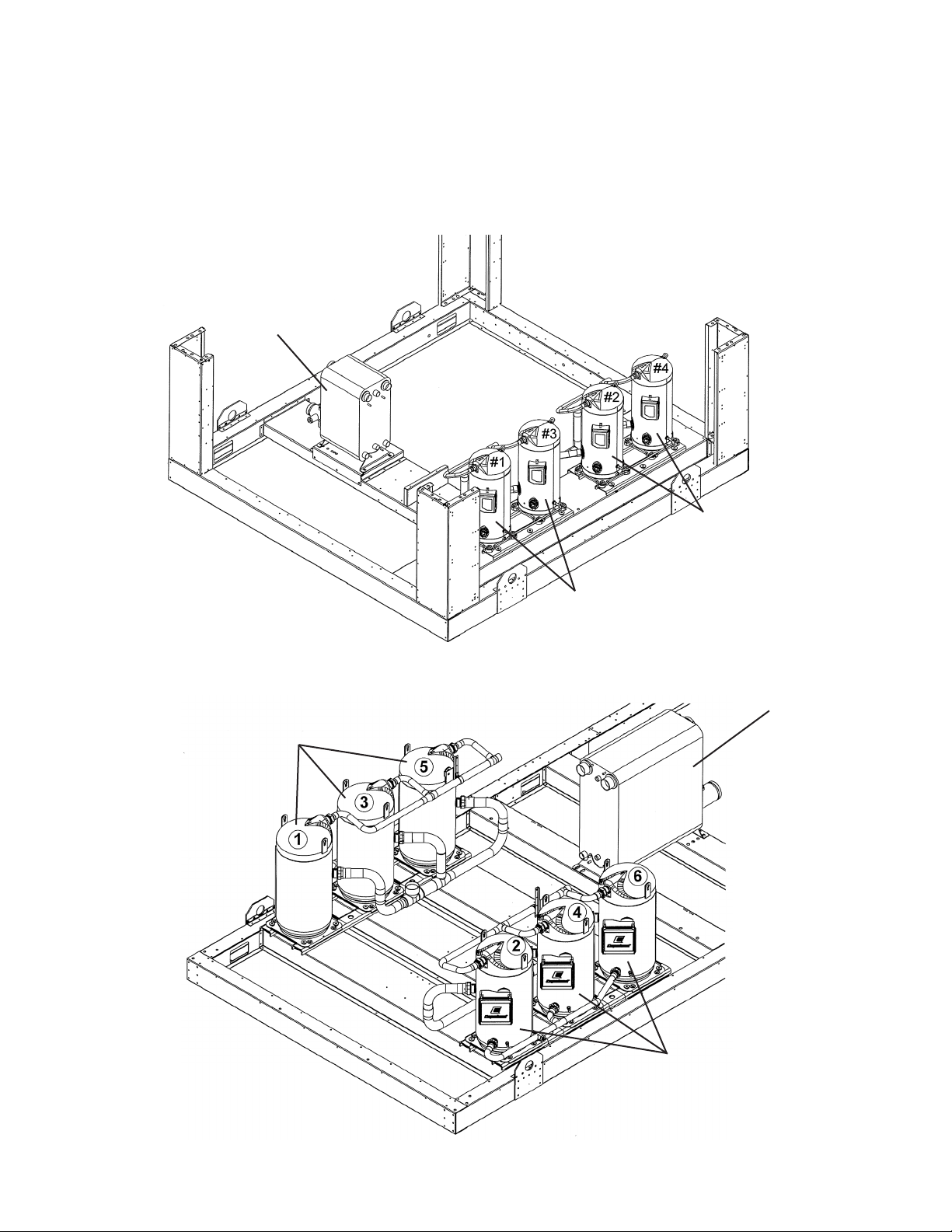
Evaporator
Refrigeration Circuit
Compressor Layout Diagrams
Circuit 2
Unit Size 075-161
Circuit 1
Evaporator
Circuit 1
Unit Size 170-180
Air-Cooled Scroll Chiller, AGZ 075-180, Vintage E, Unit Rev. 00 Rev. C 11/15 RPL 7000508 / Page 12
Circuit 2
Page 13

Refrigeration Circuit
Compressors
AGZ 075
The original compressors in the 075E units are Tandem Assemblies. The part numbers listed below are for SINGLE
Compressors. When replacing a single Compressor from a Tandem Assembly, the original piping is reused. When the
unit has an unequal Tandem Assembly (two Compressors with different HP ratings; Circuit 2 below), conrm the HP of
the required Compressor before ordering.
Unit Size
075E
Ref. Part Part
No. Description Number
1 Compressor- Circuit 1 20 HP 500559901 1
Compressor- Circuit 1 20 HP
Compressor- Circuit 1 20 HP 500559902 1
1
1
208/230V
380V
400/460V
Compressor- Circuit 1 20 HP 500559904 1
3 Compressor- Circuit 1 20 HP 500559901 1
Compressor- Circuit 1 20 HP
Compressor- Circuit 1 20 HP 500559902 1
1
1
Compressor- Circuit 1 20 HP 500559904 1
2 Compressor- Circuit 2 15 HP 300046105 1
Compressor- Circuit 2 15 HP
Compressor- Circuit 2 15 HP 300046108 1
1
1
Compressor- Circuit 2 15 HP 300046110 1
4 Compressor- Circuit 2 20 HP 500559901 1
Compressor- Circuit 2 20 HP
Compressor- Circuit 2 20 HP 500559902 1
1
1
Compressor- Circuit 2 20 HP 500559904 1
N/S Crankcase Heater- 90W (for 15 HP) 070902801 1 1 1 1
N/S Crankcase Heater- 120W (for 20 HP) 333613201 3
N/S= Not shown on diagram
1
For 380V Compressors, contact Daikin Applied with unit model and serial number to identify the correct compressor(s).
3
3
3
575V
Air-Cooled Scroll Chiller, AGZ 075-180, Vintage E, Unit Rev. 00 Rev. C 11/15 RPL 7000508 / Page 13
Page 14

Refrigeration Circuit
Compressors
AGZ 080- 100
Unit Size
080E 090E 100E
Ref. Part Part
No. Description Number
380V
208/230V
575V
400/460V
380V
208/230V
575V
400/460V
380V
208/230V
400/460V
1 Compressor- Circuit #1 20 HP 500559901 1
Compressor- Circuit #1 20 HP
Compressor- Circuit #1 20 HP 500559902 1
1
1
Compressor- Circuit #1 20 HP 500559904 1
Compressor- Circuit #1 25 HP 500560101 1 1
Compressor- Circuit #1 25 HP
1
1 1
Compressor- Circuit #1 25 HP 500560102 1 1
Compressor- Circuit #1 25 HP 500560104 1 1
3 Compressor- Circuit #1 20 HP 500559901 1 1
Compressor- Circuit #1 20 HP
1
1 1
Compressor- Circuit #1 20 HP 500559902 1 1
Compressor- Circuit #1 20 HP 500559904 1 1
Compressor- Circuit #1 25 HP 500560101 1
Compressor- Circuit #1 25 HP
1
1
Compressor- Circuit #1 25 HP 500560102 1
Compressor- Circuit #1 25 HP 500560104 1
2 Compressor- Circuit #2 20 HP 500559901 1 1
Compressor- Circuit #2 20 HP
Compressor- Circuit #2 20 HP 500559902 1 1
1
1 1
Compressor- Circuit #2 20 HP 500559904 1 1
Compressor- Circuit #2 25 HP 500560101 1
Compressor- Circuit #2 25 HP
1
1
Compressor- Circuit #2 25 HP 500560102 1
Compressor- Circuit #2 25 HP 500560104 1
575V
4 Compressor- Circuit #2 20 HP 500559901 1
Compressor- Circuit #2 20 HP
1
1
Compressor- Circuit #2 20 HP 500559902 1
Compressor- Circuit #2 20 HP 500559904 1
Compressor- Circuit #2 25 HP 500560101 1
Compressor- Circuit #2 25 HP
1
1
Compressor- Circuit #2 25 HP 500560102 1
Compressor- Circuit #2 25 HP 500560104 1
Compressor- Circuit #2 30 HP 500563901 1
Compressor- Circuit #2 30 HP
1
1
Compressor- Circuit #2 30 HP 500563902 1
Compressor- Circuit #2 30 HP 500563904 1
N/S Crankcase Heater- 120W (for 20, 25 HP) 333613201 4 4 4 4 4 4 4 4 3 3 3 3
N/S Crankcase Heater- 140W (for 30 HP) 333613202 1 1 1 1
N/S= Not shown on diagram
1
For 380V Compressors, contact Daikin Applied with unit model and serial number to identify the correct compressor(s).
Air-Cooled Scroll Chiller, AGZ 075-180, Vintage E, Unit Rev. 00 Rev. C 11/15 RPL 7000508 / Page 14
Page 15

Refrigeration Circuit
Compressors
AGZ 110- 130
Unit Size
110E 120E 130E
Ref. Part Part
No. Description Number
380V
208/230V
575V
400/460V
380V
208/230V
575V
400/460V
380V
208/230V
400/460V
1 Compressor- Circuit #1 30 HP 500563901 1 1 1
Compressor- Circuit #1 30 HP
Compressor- Circuit #1 30 HP 500563902 1 1 1
1
1 1 1
Compressor- Circuit #1 30 HP 500563904 1 1 1
3 Compressor- Circuit #1 25 HP 500560101 1
Compressor- Circuit #1 25 HP
1
1
Compressor- Circuit #1 25 HP 500560102 1
Compressor- Circuit #1 25 HP 500560104 1
Compressor- Circuit #1 30 HP 500563901 1 1
Compressor- Circuit #1 30 HP
Compressor- Circuit #1 30 HP 500563902 1 1
1
1 1
Compressor- Circuit #1 30 HP 500563904 1 1
2 Compressor- Circuit #2 25 HP 500560101 1
Compressor- Circuit #2 25 HP
1
1
Compressor- Circuit #2 25 HP 500560102 1
Compressor- Circuit #2 25 HP 500560104 1
Compressor- Circuit #2 30 HP 500563901 1 1
Compressor- Circuit #2 30 HP
Compressor- Circuit #2 30 HP 500563902 1 1
1
1 1
Compressor- Circuit #2 30 HP 500563904 1 1
575V
4 Compressor- Circuit #2 30 HP 500563901 1 1
Compressor- Circuit #2 30 HP
1
1 1
Compressor- Circuit #2 30 HP 500563902 1 1
Compressor- Circuit #2 30 HP 500563904 1 1
Compressor- Circuit #2 40 HP 500563801 1
Compressor- Circuit #2 40 HP
1
1
Compressor- Circuit #2 40 HP 500563802 1
Compressor- Circuit #2 40 HP 500563804 1
N/S Crankcase Heater- 120W (for 25 HP) 333613201 2 2 2 2
N/S Crankcase Heater- 140W (for 30, 40 HP) 333613202 2 2 2 2 4 4 4 4 4 4 4 4
N/S= Not shown on diagram
1
For 380V Compressors, contact Daikin Applied with unit model and serial number to identify the correct compressor(s).
Air-Cooled Scroll Chiller, AGZ 075-180, Vintage E, Unit Rev. 00 Rev. C 11/15 RPL 7000508 / Page 15
Page 16

Refrigeration Circuit
Compressors
AGZ 140- 161
Unit Size
140E 150E 161E
Ref. Part Part
No. Description Number
380V
208/230V
575V
400/460V
380V
208/230V
575V
400/460V
380V
208/230V
400/460V
1 Compressor- Circuit #1 40 HP 500563801 1 1 1
Compressor- Circuit #1 40 HP
Compressor- Circuit #1 40 HP 500563802 1 1 1
1
1 1 1
Compressor- Circuit #1 40 HP 500563804 1 1 1
3 Compressor- Circuit #1 30 HP 500563901 1 1
Compressor- Circuit #1 30 HP
Compressor- Circuit #1 30 HP 500563902 1 1
1
1 1
Compressor- Circuit #1 30 HP 500563904 1 1
Compressor- Circuit #1 40 HP 500563801 1 1
Compressor- Circuit #1 40 HP
1
1 1
Compressor- Circuit #1 40 HP 500563802 1 1
Compressor- Circuit #1 40 HP 500563804 1 1
2 Compressor- Circuit #2 30 HP 500563901 1
Compressor- Circuit #2 30 HP
1
1
Compressor- Circuit #2 30 HP 500563902 1
Compressor- Circuit #2 30 HP 500563904 1
Compressor- Circuit #2 40 HP 500563801 1 1
Compressor- Circuit #2 40 HP
1
1 1
Compressor- Circuit #2 40 HP 500563802 1 1
Compressor- Circuit #2 40 HP 500563804 1 1
575V
4 Compressor- Circuit #2 40 HP 500563801 1 1 1
Compressor- Circuit #2 40 HP
1
1 1 1
Compressor- Circuit #2 40 HP 500563802 1 1 1
Compressor- Circuit #2 40 HP 500563804 1 1 1
N/S Crankcase Heater- 140W (for 30, 40 HP) 333613202 4 4 4 4 4 4 4 4 4 4 4 4
N/S= Not shown on diagram
1
For 380V Compressors, Contact Daikin Applied with unit model and serial number to identify the correct compressor(s).
Air-Cooled Scroll Chiller, AGZ 075-180, Vintage E, Unit Rev. 00 Rev. C 11/15 RPL 7000508 / Page 16
Page 17

Refrigeration Circuit
Compressors
AGZ 170, 180
Unit Size
170E 180E
Ref. Part Part
No. Description Number
1 Compressor- Circuit #1 25 HP 500560101 1
Compressor- Circuit #1 25 HP
1
1
380V
208/230V
Compressor- Circuit #1 25 HP 500560102 1
Compressor- Circuit #1 25 HP 500560104 1
Compressor- Circuit #1 30 HP 500563901 1
Compressor- Circuit #1 30 HP
Compressor- Circuit #1 30 HP 500563902 1
1
1
Compressor- Circuit #1 30 HP 500563904 1
3 Compressor- Circuit #1 25 HP 500560101 1
Compressor- Circuit #1 25 HP
1
1
Compressor- Circuit #1 25 HP 500560102 1
Compressor- Circuit #1 25 HP 500560104 1
Compressor- Circuit #1 30 HP 500563901 1
Compressor- Circuit #1 30 HP
Compressor- Circuit #1 30 HP 500563902 1
1
1
Compressor- Circuit #1 30 HP 500563904 1
575V
400/460V
380V
208/230V
400/460V
575V
5 Compressor- Circuit #1 30 HP 500563901 1 1
Compressor- Circuit #1 30 HP
Compressor- Circuit #1 30 HP 500563902 1 1
1
1 1
Compressor- Circuit #1 30 HP 500563904 1 1
2 Compressor- Circuit #2 30 HP 500563901 1 1
Compressor- Circuit #2 30 HP
Compressor- Circuit #2 30 HP 500563902 1 1
1
1 1
Compressor- Circuit #2 30 HP 500563904 1 1
4 Compressor- Circuit #2 30 HP 500563901 1 1
Compressor- Circuit #2 30 HP
Compressor- Circuit #2 30 HP 500563902 1 1
1
1 1
Compressor- Circuit #2 30 HP 500563904 1 1
6 Compressor- Circuit #2 30 HP 500563901 1 1
Compressor- Circuit #2 30 HP
Compressor- Circuit #2 30 HP 500563902 1 1
1
1 1
Compressor- Circuit #2 30 HP 500563904 1 1
N/S Crankcase Heater- 120W (for 25 HP) 333613201 2 2 2 2
N/S Crankcase Heater- 140W (for 30 HP) 333613202 4 4 4 4 6 6 6 6
N/S= Not shown on diagram
1
For 380V Compressors, Contact Daikin Applied with unit model and serial number to identify the correct compressor(s).
Air-Cooled Scroll Chiller, AGZ 075-180, Vintage E, Unit Rev. 00 Rev. C 11/15 RPL 7000508 / Page 17
Page 18

Refrigeration Circuit
Evaporator
Plate to Plate Evaporator, Universal Connection (without insulation)
Unit Sizes Part Number Unit Sizes Part Number
075 332865601 130 332865607
080, 090 332865602 140 332865608
100 332865604 150, 161 332865609
110 332865605 170 332865610
120 332865606 180 332865612
Unit Sizes
Ref. # Description Part Number 075-180
N/S Sensor Well 047441511 1
N/S Heater, Evaporator, 100W 331759202 1
N/S Thermostat, 1-Stage 019754700 1
N/S = Not Shown on diagram.
002
003
001
Evaporator
Ref.# Description Part Number 075-130 140-180
001 Pipe Assembly 331598011 1
001 Pipe Assembly 331598013 1
002 Clamp- Victaulic, 2.88” OD 331597903 1
002 Clamp- Victaulic, 2.88” OD 331597904 1
003 Flow Sensor with Adapter 331893901 1 1 1
Adapter only 331893903 1 1
N/S Cable- Flow Sensor (10 Meter) 330571403 1 1 1
N/S = Not shown on diagram
1
Included in Electronic Water Flow Switch Kit 331776619.
Air-Cooled Scroll Chiller, AGZ 075-180, Vintage E, Unit Rev. 00 Rev. C 11/15 RPL 7000508 / Page 18
Page 19

Refrigeration Circuit
Evaporator Insulation
222
224
221
Single Double
Unit Size Ref.# Description Part Number Insulation Insulation
075- 180 220 Insulation, Refrigerant Side 332776702 1 2
075-130 221 Insulation, Water Side 332776701 1 2
140-180 221 Insulation, Water Side 332776730 1 2
220
Evaporator
075 222 Insulation, Wrap 332776715 1 1
080-090 222 Insulation, Wrap 332776714 1 1
100 222 Insulation, Wrap 332776716 1 1
110 222 Insulation, Wrap 332776710 1 1
120 222 Insulation, Wrap 332776717 1 1
130 222 Insulation, Wrap 332776718 1 1
140 222 Insulation, Wrap 332776719 1 1
150-161 222 Insulation, Wrap 332776720 1 1
170 222 Insulation, Wrap 332776721 1 1
180 222 Insulation, Wrap 332776723 1 1
075 224 Insulation, Wrap 047662050 1 8 sq. ft.
080-090 224 Insulation, Wrap 047662050 1 9 sq. ft.
100 224 Insulation, Wrap 047662050 1 10 sq. ft.
110 224 Insulation, Wrap 047662050 1 11 sq. ft.
120 224 Insulation, Wrap 047662050 1 12 sq. ft.
130 224 Insulation, Wrap 047662050 1 13 sq. ft.
140 224 Insulation, Wrap 047662050 1 13 sq. ft.
150-161 224 Insulation, Wrap 047662050 1 14 sq. ft.
170 224 Insulation, Wrap 047662050 1 15 sq. ft.
180 224 Insulation, Wrap 047662050 1 16 sq. ft.
075-180 N/S Insulation Tape (sold by the foot) 330461101 Varies Varies
1
Insulation p/n 047662050 is sold by the square foot.
Air-Cooled Scroll Chiller, AGZ 075-180, Vintage E, Unit Rev. 00 Rev. C 11/15 RPL 7000508 / Page 19
.
Page 20

Refrigeration Circuit
Liquid Line Piping Diagram
L116
L113
Unit Size 110-130 shown
Circuit #1 w/o HGBP
L153
L152
L151
L106
L108
L110
L104
L111
L103
Air-Cooled Scroll Chiller, AGZ 075-180, Vintage E, Unit Rev. 00 Rev. C 11/15 RPL 7000508 / Page 20
Page 21

Refrigeration Circuit
Liquid Line Piping Components
Ref.# Description Part Number Quantity
L103 Electronic Expansion Valve (075-100) 331775303 1 per circuit
L103 Electronic Expansion Valve (110-180) 331775304 1 per circuit
N/S Cable, Electr Expansion Valve 334549502 1 per circuit
L104 Sight Glass 1.125” 330508602 1 per circuit
L106 Valve- Solenoid, 1.12” (075-130) 331761603 1 per circuit
L106 Valve- Solenoid, 1.12” (140-180) 331761609 1 per circuit
SV1,2 (N/S) Cable, Liquid Line Solenoid, 32 ft. 330286404 1 per circuit
L108 Filter Drier- Shell 019190500 1 per circuit
L110 Filter Drier- Core 330694401 2 per circuit
L111 Felt Gasket Kit 074783601 2 per circuit
L113 Shut Off Valve, 1.12” 048169601 1 per circuit
L116 Valve- Charge .37” x .37” 038689900 1 per circuit
L151 Valve- Schrader 071100801 1 per circuit
L152 Valve- Core 026541100 1 per circuit
L153 Valve- Cap 032943500 1 per circuit
N/S = Not shown on diagram
Air-Cooled Scroll Chiller, AGZ 075-180, Vintage E, Unit Rev. 00 Rev. C 11/15 RPL 7000508 / Page 21
Page 22

Refrigeration Circuit
Unit Size 110-130 shown
Discharge Line Piping Diagrams
D110
D105
Chicago Code
D142
D153
D152
D151
D151
D152
Circuit #1 w/o HGBP
Ref.# Description Part Number Quantity
D105 Valve- Discharge Shut-Off, 1.625” 330296045 1 per circuit
D110 Valve- Solenoid, 1.12 (sizes 075-100 & 140-180) 331761605 1 per circuit
D110 Valve- Solenoid, 1.38 (sizes 110-130) 331761604 1 per circuit
N/S Connector, Discharge Solenoid 331996402 1 per circuit
D142 Valve- Relief (Chicago Code, Code 46 = B,C,F,V) 332943690 1 per circuit
D151 Valve- Schrader 071100801 2 per circuit *
D152 Valve- Core 026541100 2 per circuit
D153 Valve- Cap 032943500 1 per circuit
* Quantity = 3 on AGZ075E, circuit 2.
N/S = Not Shown on diagram
Air-Cooled Scroll Chiller, AGZ 075-180, Vintage E, Unit Rev. 00 Rev. C 11/15 RPL 7000508 / Page 22
Page 23

Refrigeration Circuit
Suction Line Piping Diagrams
S112
S150
S153
S152
S151
Unit Size 075- 130 shown
Circuit #1 with optional Suction Valve
S102
Quantity
Ref.# Description Part Number Circuit 1 Circuit 2
S102 Suction Valve- Ball 2.625”, Ckt 1 (Code 30=V, Size 075) 330296047 1
S102 Suction Valve- Ball 2.125”, Ckt 2 (Code 30=V, Size 075) 330296046 1
S102 Suction Valve- Ball 2.625” (Code 30=V, Sizes 080-180) 330296047 1 1
S112 Fusible Plug .38” NPT 331543401 1 1
S150 Valve- Charge .37” x .37” 038689900 1 1
S151 Valve- Schrader 071100801 1 1
S152 Valve- Core 026541100 1 1
S153 Valve- Cap 032943500 1 1
Air-Cooled Scroll Chiller, AGZ 075-180, Vintage E, Unit Rev. 00 Rev. C 11/15 RPL 7000508 / Page 23
Page 24

Refrigeration Circuit
Hot Gas Bypass Piping Diagrams
HG12
HG11
HG14
HG153
HG152
Unit Size 110-130 Shown
HG151
Circuit #1
Ref.# Description Part Number Units with HGBP
(Code 29=NH,VH)
Quantity
HG11 Valve, Angle .88 (Unit Sizes 075-100) 072401302 1 per circuit
HG11 Valve, Shut off 1.12 (Unit Sizes 110-180) 048169601 1 per circuit
HG12 Valve- Solenoid (Unit Sizes 075-100) 331761602 1 per circuit
HG12 Valve- Solenoid (Unit Sizes 110-180) 331761603 1 per circuit
SV5,6 (N/S) Cable, HGBP Solenoid 330286404 1 per circuit
HG14 Valve- HGBP (Unit Sizes 075-100) 331761701 1 per circuit
HG14 Valve- HGBP (Unit Sizes 110-180) 331761702 1 per circuit
HG151 Valve- Schrader 071100801 1 per circuit
HG152 Core- Schrader Valve 026541100 1 per circuit
HG153 Cap- Schrader Valve 032943500 1 per circuit
N/S Cable- Sol. & HGBP Valves 330286404 2 per circuit
N/S= Not shown on diagram
Air-Cooled Scroll Chiller, AGZ 075-180, Vintage E, Unit Rev. 00 Rev. C 11/15 RPL 7000508 / Page 24
Page 25

Refrigeration Circuit
Sensor & Transducer Location Diagram
HP2
501
501
502
S13
S12
HP1
S00
S08
Air-Cooled Scroll Chiller, AGZ 075-180, Vintage E, Unit Rev. 00 Rev. C 11/15 RPL 7000508 / Page 25
502
Page 26

Refrigeration Circuit
Sensor & Transducer Components
Ref. Description Part Qty
No. Number
HP1 Switch- High Pressure Circuit #1, 650 psi (Code 46= A,D,E,W,Z) 331542401 1
HP1 Switch- High Pressure Circuit #1, 540 psi (Code 46= B,C,F,V - Chicago) 331542402 1
HP2 Switch- High Pressure Circuit #2, 650 psi (Code 46= A,D,E,W,Z) 331542401 1
HP2 Switch- High Pressure Circuit #2, 540 psi (Code 46= B,C,F,V - Chicago) 331542402 1
S00 Sensor- Leaving Water Temperature, 354" 349982403 1
S05* Sensor- Outside Air Temperature, 236" 349982402 1
S08 Sensor- Entering Water Temperature, 236" 349982402 1
S12 Sensor- Suction Temperature Circuit #1, 236" 349982402 1
S13 Sensor- Suction Temperature Circuit #2, 236" 349982402 1
501 Transducer- Low Pressure, Circuits 1 & 2 Suction (S01, S02) 910153379 2
502 Transducer- High Pressure, Circuits 1 & 2 Discharge (S03, S04) 910153045
N/S Cable for Transducers, 16 ft. 074667502 4
N/S = Not shown on diagram
* Not shown on diagram. Mounted below the condenser coil rail.
2
Air-Cooled Scroll Chiller, AGZ 075-180, Vintage E, Unit Rev. 00 Rev. C 11/15 RPL 7000508 / Page 26
Page 27

Refrigeration Circuit
Miscellaneous Components
Compressor Sound Enclosures (Code 06= SB)
Description Part Number Quantity
Sound Enclosure Kit Unit Size 075 334704801 One kit per unit
Sound Enclosure Kit Unit Size 080- 090 331776633 One kit per unit
Sound Enclosure Kit Unit Size 100 334704802
Sound Enclosure Kit Unit Size 110 334704803 One kit per unit
Sound Enclosure Kit Unit Size 120 334704804 One kit per unit
Sound Enclosure Kit Unit Size 130, 208/230V 334704805 One kit per unit
Sound Enclosure Kit Unit Size 130, all other voltages 334704804 One kit per unit
Sound Enclosure Kit Unit Size 140, 208/230V 334704806 One kit per unit
Sound Enclosure Kit Unit Size 140, all other voltages 334704804 One kit per unit
One kit per unit
Sound Enclosure Kit Unit Size 150, 208/230V 334704807 One kit per unit
Sound Enclosure Kit Unit Size 150, all other voltages 334704804 One kit per unit
Sound Enclosure Kit Unit Size 161, 208/230V 334704815 One kit per unit
Sound Enclosure Kit Unit Size 161, all other voltages 334704804 One kit per unit
Sound Enclosure Kit Unit Size 170 334704809 One kit per unit
Sound Enclosure Kit Unit Size 180 334704810 One kit per unit
Air-Cooled Scroll Chiller, AGZ 075-180, Vintage E, Unit Rev. 00 Rev. C 11/15 RPL 7000508 / Page 27
Page 28

Condenser Section
Fan Motor and Fan Deck Diagram
950
904
901
903903
902
Air-Cooled Scroll Chiller, AGZ 075-180, Vintage E, Unit Rev. 00 Rev. C 11/15 RPL 7000508 / Page 28
Page 29

Condenser Section
Fan Motor and Fan Deck Components & Condenser Coils
Fan Motor and Fan Deck Components
Ref.# Description Part Number Quantity
901 Motor- 2.0 HP, 208/60/3, 230/60/3 330423301 1 per fan
901 Motor- 2.0 HP, 380/60/3, 460/60/3 330293901 1 per fan
901 Motor- 2.0 HP, 400/50/3 330423301 1 per fan
901 Motor- 2.0 HP, 575/60/3 330423701 1 per fan
902 Fan Blade- 30” 330294001 1 per fan
903 Motor Mounting Bracket (2 per motor) 330260701 2 per fan
904 Fan Venturi Panel 330288202 1 per fan
950 Grille- Fan 331444501 1 per fan
Unit Sizes Number of Fans per Unit
075-100 6
110-130 8
140-180 10
Condenser Coils
Condenser Coil Part Number 075-100 110-130 140-180
Microchannel, Standard (Code 8 = M) 333984631 6 8 10
Microchannel, Electron Coated (Code 8 =P) 331984632 6 8 10
Air-Cooled Scroll Chiller, AGZ 075-180, Vintage E, Unit Rev. 00 Rev. C 11/15 RPL 7000508 / Page 29
Page 30

Coil Grilles and Coil Louvers
Coil Louvers Shown
Unit Size 075-100
W51
Control Box End
W41
W50
W42
W52
W40
Opposite End
Unit Size
Ref.# Description Part Number 075-100 110-130 140-180
Coil Grilles
W40 Support Post- Side 332866180 2 4 4
W41 Support Post- Control Box End 332866080 1 1 1
W42 Support Post- Opposite End 332866081 1 1 1
W50 Coil Grille- Side 332866100 6 8 10
W51 Coil Grille- Control Box End 332866130 2 2 2
W52 Coil Grille- Opposite End 332866131 2 2 2
N/S Screw .25-20 x .625 331578401 40 48 56
Coil Louvers
W40 Support Post- Side 332866180 2 4 4
W41 Support Post- Control Box End 332866080 1 1 1
W42 Support Post- Opposite End 332866081 1 1 1
W50 Coil Louver- Side 332866090 6 8 10
W51 Coil Louver- Control Box End 332866140 2 2 2
W52 Coil Louver- Opposite End 332866141 2 2 2
N/S Screw .25-20 x .400 331578403 60 72 84
N/S = Not shown on diagram
Coil Grille Kit 075-100 (includes all components above) 334704701
Coil Grille Kit 110-130 (includes all components above) 334704702
Coil Grille Kit 140-180 (includes all components above) 334704703
Coil Louver Kit 075-100 (includes all components above) 334704711
Coil Louver Kit 110-130 (includes all components above) 334704712
Coil Louver Kit 140-180 (includes all components above) 334704713
End Louver Kit 075-180 - includes (1)W41, (1)W42, (2)W51, (2)W52 and (24) screws 334704721
Air-Cooled Scroll Chiller, AGZ 075-180, Vintage E, Unit Rev. 00 Rev. C 11/15 RPL 7000508 / Page 30
Page 31

Base Grilles
Opposite
W60
End
W62
Opposite
End
W60
Control
Box
End
Unit Size 075-100
W61
Control
Box
End
W60
W63
W62
W61
Unit Size 110-130
Opposite
End
W61
W64
Control
Box End
Air-Cooled Scroll Chiller, AGZ 075-180, Vintage E, Unit Rev. 00 Rev. C 11/15 RPL 7000508 / Page 31
W61
Unit Size 140-180
Page 32

Base Grilles
Ref.# Description Part Number 075-100 110-130 140-180
W60 Base Grille- Opposite End 332866150 2 2 2
W61 Base Grille- Side (34.90 x 41.44) 332866120 4 4 8
W62 Base Grille- Side (34.90 x 39.29) 332866122 2 2
W63 Base Grille- Side (34.90 x 44.74) 332866123 2
W64 Base Grille- Side (34.90 x 36.59) 332866124 2
N/S Screw- .25 x 20, .625 331578401 32 40 48
N/S = Not shown on diagram
Base Grille Kit 075-100 (includes all components above) 334704706
Base Grille Kit 110-130 (includes all components above) 334704707
Base Grille Kit 140-180 (includes all components above) 334704708
Unit Size
Air-Cooled Scroll Chiller, AGZ 075-180, Vintage E, Unit Rev. 00 Rev. C 11/15 RPL 7000508 / Page 32
Page 33

Base Louvers
Unit Size
075-100
Control Box
End
Control Box
End
W61
W61
W62
W62
W63
W63
Opposite
Unit Size
110-130
Opposite
End
End
W70
W62
W71
W60
W70
W62
W71
W60
Unit Size
Control Box
140-180
End
W62
W61
W63
W62
W61
Air-Cooled Scroll Chiller, AGZ 075-180, Vintage E, Unit Rev. 00 Rev. C 11/15 RPL 7000508 / Page 33
Opposite
End
W60
W70
W62
W62
W63
W70
Page 34

Base Louvers
Ref.# Description Part Number 075-100 110-130 140-180
W60 Base Louver- Opposite End 332866160 2 2 2
W61 Base Louver- Side (35.90 x 44.67) 332866172 1 1 2
W62 Base Louver- Side (35.90 x 39.28) 332866170 2 4 4
W63 Base Louver- Side (35.90 x 39.64) 332866116 1
W63 Base Louver- Side (35.90 x 45.52) 332866176 1
W63 Base Louver- Side (35.90 x 36.64) 332866111 2
W70 Base Louver- Side (35.90 x 44.67) 332866173 1 1 2
W71 Base Louver- Side (35.90 x 39.64) 332866117 1
W71 Base Louver- Side (35.90 x 45.52) 332866177 1
N/S Screw- .25 x 20, .400 331578403 48 60 72
N/S = Not shown on diagram
Base Louver Kit 075-100 (includes all components above) 334704716
Base Louver Kit 110-130 (includes all components above) 334704717
Base Louver Kit 140-180 (includes all components above) 334704718
Unit Size
Air-Cooled Scroll Chiller, AGZ 075-180, Vintage E, Unit Rev. 00 Rev. C 11/15 RPL 7000508 / Page 34
Page 35

Optional Equipment
Alarm Bell Kit
Description Part Number Qty.
Alarm Bell Kit (includes Alarm Bell and Relay) 058090104 1
Alarm Bell 017809400 1
Relay, SPDT, 30A, 120VA 072937402 1
HGBP Kit
The HGBP Kit is designed to add the hot gas bypass option when Code 29= FH (Hot Gas Ready).
If Code 29= NN or VN (not Hot Gas Ready) must also order T4 Transformer Kit 331776675.
Description Part Number Qty.
HGBP Kit (includes components for both circuits)
Unit Sizes 075-100 331776673 1
Unit Sizes 110-180 331776674 1
Water Flow Indicator
Description Part Number Qty.
Water Flow Switch- Paddle Type 017503301 1
Water Flow Switch Kit- Electronic
-includes Sensor, Adapter and Cable 331776619 1
Water Flow Sensor with Adapter 331893901 1
Adapter 331893903 1
Cable- Water Flow Sensor, 10 Meter 330571403 1
Evaporator Strainer Kit
Description Part Number Qty.
Evaporator Strainer Kit
Unit Size 075-130 331758922 1
Unit Size 140-180 331758923 1
Control Box Exhaust Fans Kit
Description Part Number Qty.
Control Box Exhaust Fan Kit 193463701 1
Control Box Heater Kit
Description Part Number Qty.
Control Box Heater Kit 349904801 1
Air-Cooled Scroll Chiller, AGZ 075-180, Vintage E, Unit Rev. 00 Rev. C 11/15 RPL 7000508 / Page 35
Page 36

Optional Equipment
115V Outlet Kit
Description Part Number Qty.
115V Outlet Kit 193463501 1
(Does not include Transformer, select from below)
Transformer Kit for 115V Outlet Kit (units without pumps)
Description Part Number Qty.
Transformer, 2.0KVA, 208V (60 Hz) 334704101 1
Transformer, 2.0KVA, 230V (60 Hz) 334704102 1
Transformer, 2.0KVA, 380V (60 Hz) 334704103 1
Transformer, 2.0KVA, 460V (60 Hz) 334704104 1
Transformer, 2.0KVA, 575V (60 Hz) 334704105 1
Transformer, 2.0KVA, 380/400/415 (50 Hz) 334704106 1
Fan VFD Kit (For converting units without fan VFDs to one fan VFD per circuit. Includes com-
ponents and wiring for both circuits, requires High Ambient Exhaust Fan Kit)
Description Part Number Qty.
Unit Sizes 075-100, 208V 334704301 1
Unit Sizes 075-100, 230V 334704304 1
Unit Sizes 075-100, 380V 334704309 1
Unit Sizes 075-100, 400-460V 334704302 1
Unit Sizes 075-100, 575V 334704303 1
Unit Sizes 110-180, 208V 334704305 1
Unit Sizes 110-180, 230V 334704306 1
Unit Sizes 110-180, 380V 334704310 1
Unit Sizes 110-180, 400-460V 334704307 1
Unit Sizes 110-180, 575V 334704308 1
Line Reactor Kit
Description Part Number Qty.
Unit Sizes 075-100, 208-230V 334704401 1
Unit Sizes 075-100, 380V 334704407 1
Unit Sizes 075-100, 400-460V 334704402 1
Unit Sizes 075-100, 575V 334704403 1
Unit Sizes 110-180, 208-230V 334704404 1
Unit Sizes 110-180, 380V 334704408 1
Unit Sizes 110-180, 400-460V 334704405 1
Unit Sizes 110-180, 575V 334704406 1
Air-Cooled Scroll Chiller, AGZ 075-180, Vintage E, Unit Rev. 00 Rev. C 11/15 RPL 7000508 / Page 36
Page 37

Optional Equipment
Phase Voltage Monitor Kit
Description Part Number Qty.
Single Point Units, 208-230V 193463801 1
Single Point Units, 380V, 400V, 460V 193463802 1
Single Point Units, 575V 193463805 1
Multi Point Units, 208-230V 193463806 1
Multi Point Units, 380V, 400V, 460V 193463807 1
Multi Point Units, 575V 193463810 1
Ground Fault Protection Kit
Description Part Number Qty.
Single Point Units, all voltages 193463901 1
Multi Point Units, all voltages 193463903 1
Rapid Restore Module Kit
Description Part Number Qty.
Rapid Restore Module Assembly 334704601 1
Remote User Interface Kit, MTIII Display Module
Description Part Number Qty.
Remote User Interface 350147416 1
Communications Module Kit
Description Part Number Qty.
LonMark 350147412 1
ModBus 350147413 1
BACnet MSTP 350147414 1
BACnet IP 350147415 1
D-Net (AWM) - Requires 115V Outlet 193528701 1
Pump Package Components
Pump Packages are generated per customer specications. Contact Daikin Applied with the unit GO number
and Serial Number including any available vendor information so that the correct part(s) can be identied.
Air-Cooled Scroll Chiller, AGZ 075-180, Vintage E, Unit Rev. 00 Rev. C 11/15 RPL 7000508 / Page 37
Page 38

7000508 Rev. C 11/2015 CPL Page 1 of 1
Critical Daikin Applied OEM Parts
Are What Your HVAC Unit Needs!
Daikin Trailblazer™ Air-Cooled Scroll Chiller
AGZ
075-180 Vintage E, Unit Revision 00
Critical Components UNIT SIZE Voltage Part Number
Control
Unit Controller (UC) ALL ALL 193407301
Circuit Control Module (CC1,2) ALL ALL 193407501
High Pressure Relay (HPR1,2) ALL ALL 349934724
Motor Protection Relay (MPR1,2) ALL ALL 349934724
Transducer- Low Pressure (S01,02) ALL ALL 910153379
Transducer- High Pressure (S03,04) ALL ALL 910153045
Sensor- Temperature, 19 ft. ALL ALL 349982402
Switch- High Pressure (HP1,2) non-Chicago Code ALL ALL 331542401
Switch- High Pressure (HP1,2) with Chicago Code ALL ALL 331542402
Switch- Main Control (SW1) ALL ALL 802005045
Compressor
See RPL 7000508
Expansion Valve
Electronic Expansion Valve 075-100 ALL 331775303
Electronic Expansion Valve 110-180 ALL 331775304
Condenser Fan Components
Motor, 2.0 HP ALL 208/230/60/3 330423301
Motor, 2.0 HP ALL 380/460/60/3 330293901
Motor, 2.0 HP ALL 400/50/3 330423301
Motor, 2.0 HP ALL 575/60/3 330423701
Fan Blade, 30" ALL ALL 330294001
Call Your Local Daikin Applied Parts Distributor For All Your Parts Needs.
To Locate A Distributor, Go To www.DaikinApplied.com or Call 1-800-37PARTS
 Loading...