

Page 1

Installation, Operating and Maintenance Manual
Optional Pump Packages for
AGZ 030C – AGZ 190C
IOMM AGZ-C
PUMP PACKAGE
SUPPLEMENT
Group: Chiller
Part Number: 331975401
Date: August 2009
Supersedes: New
Page 2
Table of Contents
Introduction........................................3
General Description................................... 3
Inspection .................................................. 3
Installation .........................................3
Field Water Piping..................................... 3
System Water Volume ............................... 4
Freeze Protection....................................... 4
Weights & Vibration Isolators ................... 4
Pump Control ............................................ 8
Freeze Protection....................................... 8
Triple-Duty Valve ............................10
Component Location........................16
Dimensions ......................................18
Pump Curves....................................23
Manufactured in an ISO Certified Facility
HAZARD IDENTIFICATION INFORMATION
Wiring Diagrams..............................33
Electrical Data..................................36
Sequence of Operation
S
tart-up.............................................56
.....................55
System Maintenance........................56
Lubrication.............................................. 56
Electrical Terminals................................. 56
Preventative Maintenance Schedule ....... 57
Warranty Statement..........................57
Service
.............................................57
!
DANGER
Dangers indicate a hazardous situation which will result in death or serious injury if not avoided.
!
WARNING
Warnings indicate potentially hazardous situations, which can result in property damage, severe
personal injury, or death if not avoided.
!
CAUTION
Cautions indicate potentially hazardous situations, which can result in personal injury or
equipment damage if not avoided.
©2008 McQuay International. Illustrations and data cover the McQuay International product at the time
of publication and we reserve the right to make changes in design and construction at anytime without
notice. ™® The following are trademarks or registered trademarks of their respective companies:
FanTrol, MicroTech II, Open Choices, and SpeedTrol from McQuay International.
2 IOMM AGZC Pump Pkg
Page 3

Introduction
General Description
This manual provides additional information on optional pump packages, factory mounted on McQuay
Model AGZ-C scroll-compressor chillers. Follow the directions in the chiller installation and
operating manuals, IMM AGZC and OM AGZC, for installation and operation of the entire unit.
Inspection
When the equipment is received, carefully check all items against the bill of lading to check for a
complete shipment. Check all units for damage upon arrival. All shipping damage must be reported
to the carrier and a claim must be filed with the carrier. Check the unit’s serial plate before unloading
the unit to be sure that it agrees with the power supply available. Physical damage to unit after
acceptance is not the responsibility of McQuay International.
Installation
Installation and maintenance are to be performed only by qualified personnel who are familiar with
local codes and regulations, and experienced with this type of equipment.
Follow the directions in IMM AGZC for installation of the unit. The addition of the optional pump
package does not change installation procedure. However, vibration isolator selection and location,
unit weights, dimensions and electrical data will differ from units without a pump package.
Field Water Piping
Due to the variety of piping practices, follow the recommendations of local authorities. They can
supply the installer with the proper building and safety codes required for a proper installation.
Design the piping with a minimum number of bends and changes in elevation to keep system cost
down and performance up. It should contain:
1. Vibration eliminators to reduce vibration and noise transmission to the building.
2. Shutoff valves to isolate the unit from the piping system during unit servicing. The pump
package has suction and discharge service shutoff valves for each pump.
3. Manual or automatic air vent valves at the high points of the system and drains at the low
parts in the system. The evaporator should not be the highest point in the piping system.
4. Some means of maintaining adequate system water pressure (i.e., expansion tank or
regulating valve).
5. Water temperature and pressure indicators located at the unit to aid in unit servicing.
6. A strainer to is provided in the package to remove foreign matter from the water before it
enters the pump and chiller. The use of a strainer will prolong pump life and help maintain
high system performance levels. The strainer must be cleaned after system flushing is
completed.
7. Any water piping to the unit must be protected to prevent freeze-up if below freezing
temperatures are expected.
8. If the unit is used with a replacement chiller on a previously existing piping system, flush
the system thoroughly prior to unit installation.
Make a preliminary leak check prior to insulating the water piping and filling the system.
Include a vapor barrier with the piping insulation to prevent moisture condensation and
possible damage to the building structure. It is important to have the vapor barrier on the
outside of the insulation to prevent condensation within the insulation on the cold surface of
the pipe.
IOMM AGZC Pump Pkg 3
Page 4

System Water Volume
It is important to have adequate water volume in the system to provide an opportunity for
the chiller to sense a load change, adjust to the change and stabilize. As the expected load
change becomes more rapid, a greater water volume is needed. The system water volume is
the total amount of water in the evaporator, air handling products and associated piping. If
the water volume is too low, operational problems can occur including rapid compressor
cycling, rapid loading and unloading of compressors, erratic refrigerant flow in the chiller,
improper motor cooling, shortened equipment life and other undesirable occurrences.
For normal comfort cooling applications where the cooling load changes relatively slowly,
we recommend a minimum system volume in gallons of 2 to 3 times the flow rate (gpm).
For example, if the design chiller flow rate is 350 gpm, we recommend a minimum system
volume of 700 to 1050 gallons.
Since there are many other factors that can influence performance, systems can successfully
operate below these suggestions. However, as the water volume decreases below these
suggestions, the possibility of problems increases.
Freeze Protection
In installations where the unit is subject to sub-freezing temperatures, some method of
preventing pipe and component freezing and subsequent damage must be employed. The
pump package has an outdoor air thermostat (TH1) that will start the pump at 40F to help
prevent freeze up. It is recommended that one or more of the following strategies also be
employed:
If chilled water circulation is not possible or desired, one or more of the following
procedures must be used.
1. Drain the outdoor portion of the system and cap with a nitrogen charge.
2. Heat trace all outdoor components.
3. Add sufficient anti-freeze to prevent freezing.
Adding of a concentration of a glycol anti-freeze with a freeze point 10 degrees F below the
lowest expected outdoor temperature will result in decreased capacity and increased
pressure drop in the chiller. AGZ units are selected to provide the required capacity with the
fluid specified, water or antifreeze.
Note: Do not use automotive grade antifreezes as it contains inhibitors harmful to chilled
water systems. Use only glycols designated for use in building cooling systems.
Weights & Vibration Isolators
Vibration isolators are recommended for all roof-mounted installations or wherever
vibration transmission is a consideration. If the pump package is installed adjacent to a
chiller that is mounted on springs, it is essential that flexible piping connections be
employed between the two units.
Initially install the unit on shims or blocks at the "free height" of the isolator. When all
piping, wiring, flushing, charging, etc. is complete, adjust the springs upward to load them
and to provide clearance to free the blocks, which are then removed.
Installation of spring isolators requires flexible pipe connections and at least three feet of
conduit flex tie-ins. Support piping and conduit independently from the unit to not stress
connections.
See pages 18 through 22 for the for mounting hole locations.
4 IOMM AGZC Pump Pkg
Page 5
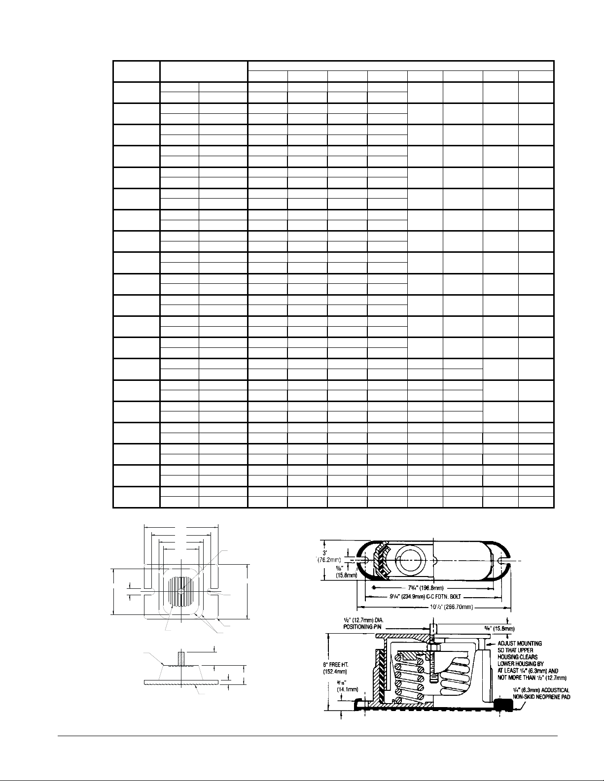
Table 1, Mounting Weights
2
A
SIZE
030
035
040
045
050
055
060
065
070
075
080
090
100
110
125
130
140
160
180
190
OPERATING.
WEIGHT lbs kg
M1 M2 M3 M4 M5 M6 M7 M8
lbs 4035 1089 1060 956 930
kg 1832 494 481 434 422
lbs 4090 1100 1084 960 946
kg 1857 499 492 436 429
lbs 4205 1123 1112 990 980
kg 1909 510 505 450 445
lbs 4335 1123 1179 992 1041
kg 1968 510 535 450 473
lbs 4465 1179 1190 1043 1053
kg 2027 535 540 474 478
lbs 4405 1176 1214 991 1023
kg 2000 534 551 450 465
lbs 4690 1212 1332 1022 1124
kg 2129 550 605 464 510
lbs 4725 1206 1335 1036 1147
kg 2145 548 606 470 521
lbs 5280 1357 1270 1370 1283
kg 2397 616 577 622 582
lbs 6690 1733 2003 1370 1583
kg 3037 787 910 622 719
lbs 6775 1800 2088 1336 1550
kg 3076 817 948 607 704
lbs 6658 1759 2030 1332 1537
kg 3023 798 922 605 698
lbs 6792 1761 2053 1375 1603
kg 3084 800 932 624 728
lbs 8650 1405 1551 1370 1513 1336 1475
kg 3927 638 704 622 687 606 670
lbs 8800 1437 1559 1407 1526 1377 1494
kg 3995 653 708 639 693 625 678
lbs 8945 1479 1627 1420 1562 1361 1497
kg 4061 672 739 645 709 618 679
lbs 13062 1613 1664 1610 1660 1605 1656 1602 1652
kg 5930 732 756 731 754 729 752 727 750
lbs 13092 1594 1604 1617 1627 1645 1655 1670 1680
kg 5944 724 728 734 739 747 751 758 763
lbs 13213 1616 1647 1628 1660 1643 1675 1656 1688
kg 5999 734 748 739 753 746 760 752 766
lbs 14834 1793 1835 1814 1857 1851 1894 1873 1917
kg 6735 814 833 824 843 840 860 850 870
MOUNTING WEIGHTS, LBS KG AGZ-C
N/A N/A N/A N/A
N/A N/A N/A N/A
N/A N/A N/A N/A
N/A N/A N/A N/A
N/A N/A N/A N/A
N/A N/A N/A N/A
N/A N/A N/A N/A
N/A N/A N/A N/A
N/A N/A N/A N/A
N/A N/A N/A N/A
N/A N/A N/A N/A
N/A N/A N/A N/A
N/A N/A N/A N/A
RP-4, Rubber-in-Shear Isolator Dimension C2PE, Spring Isolator Dimensions
6.25
3.87
.56 TYP.
5.00
3.75
3.00
R4
VM&C
ø .500-13NC-2B
VM&C
R.28
TYP.
4.63
N/A N/A
N/A N/A
N/A N/A
R4
RECESSED
GRIP RIBS
DURULENE
MATERIAL
NOTES:
MOUNT MATERIAL TO BE DURULENE RUBBER.1.
MOLDED STEEL AND ELASTOMER MOUNT FOR
.
OUTDOOR SERVICE CONDITIONS.
3. RP-4 MOUNT VERSION WITH STUD IN PLACE.
DRAWING NUMBER 3314814
ALL DIMENSIONS ARE IN DECIMAL INCHES
R.250 TYP.
R.750 TYP.
1.13 ± .25
PPROX.
.38
RAISED GRIP RIBS
1.63
IOMM AGZC Pump Pkg 5
Page 6
Rubber-In- Shear Isolators
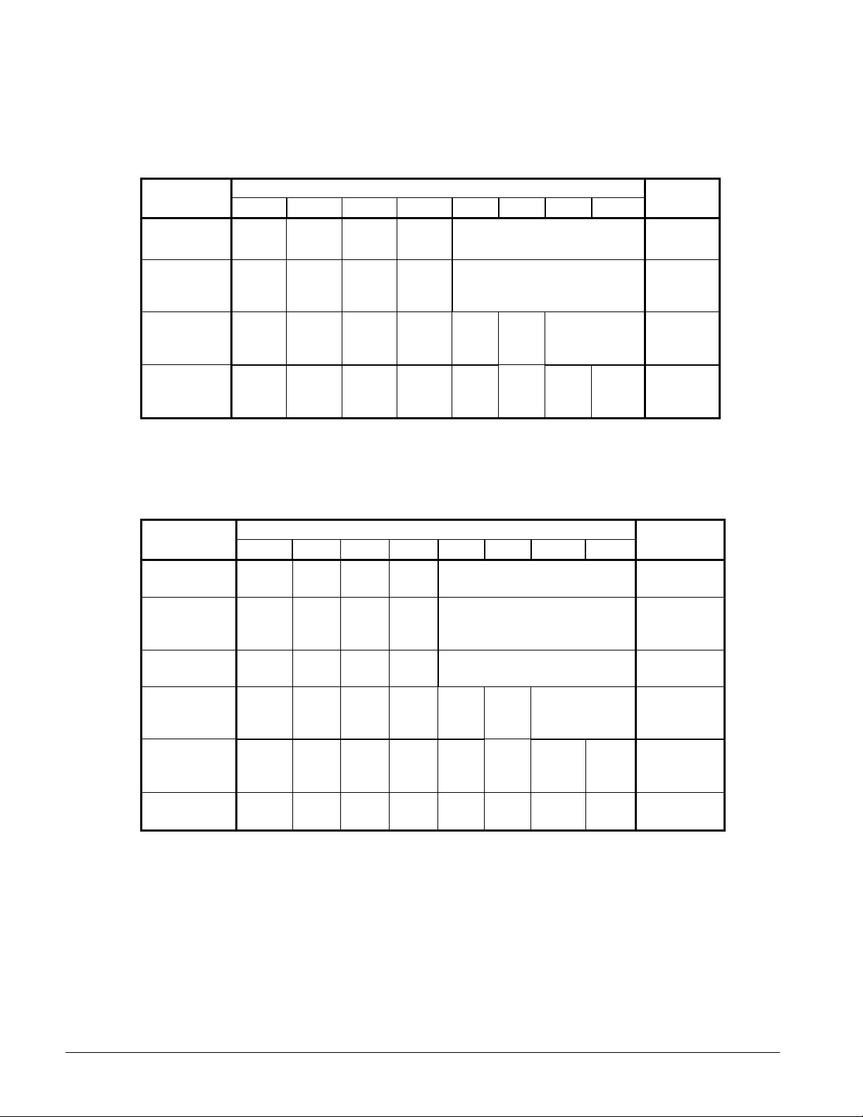
Table 2, Rubber-in-Shear Isolator Locations, Aluminum Fin
Mounting hole location dimensions are on the unit dimension drawings beginning on page 18. The
isolator selections are different for AGZ units with pump packages than those without.
AGZ-C
Size
030, 035, 040
045. 050, 055
060, 065, 070
075, 080, 090
100
110, 125, 130
140, 160, 180
190
M1 M2 M3 M4 M5 M6 M7 M8
RP-4 RP-4 RP-4 RP-4
Brown Brown Brown Brown
RP-4 RP-4 RP-4 RP-4
Brick
Red
RP-4 RP-4 RP-4 RP-4 RP-4 RP-4
Brick
Red
RP-4 RP-4 RP-4 RP-4 RP-4 RP-4 RP-4 RP-4
Brick
Red
Brick
Red
Brick
Red
Brick
Red
RUBBER-IN-SHEAR ISOLATORS
Brick
Red
Brick
Red
Brick
Red
Brick
Red
Brick
Red
Brick
Red
Brick
Red
Brick
Red
Brick
Red
Brick
Red
Brick
Red
Brick
Red
Table 3, Rubber-in-Shear Isolator Locations, Copper Fin
Mounting hole location dimensions are on the unit dimension drawings beginning on page 18. The
isolator selections are different for AGZ units with pump packages than those without.
AGZ-C
Size
030, 035, 040
045, 050
055, 060, 065
070
075, 080, 090
100
110, 125, 130
140, 160, 180
190
M1 M2 M3 M4 M5 M6 M7 M8
RP-4 RP-4 RP-4 RP-4
Brown Brown Brown Brown
RP-4 RP-4 RP-4 RP-4
Brick
Red
RP-4 RP-4 RP-4 RP-4
Lime Lime Lime Lime
RP-4 RP-4 RP-4 RP-4 RP-4 RP-4
Brick
Red
RP-4 RP-4 RP-4 RP-4 RP-4 RP-4 RP-4 RP-4
Brick
Red
RP-4 RP-4 RP-4 RP-4 RP-4 RP-4 RP-4 RP-4
Lime Lime Lime Lime Lime Lime Lime Lime
Brick
Red
Brick
Red
Brick
Red
RUBBER-IN-SHEAR ISOLATORS
Brick
Red
Brick
Red
Brick
Red
Brick
Red
Brick
Red
Brick
Red
Brick
Red
Brick
Red
Brick
Red
Brick
Red
Brick
Red
Brick
Red
KIT
NUMBERS
332325107
332325108
332325109
332325110
KIT
NUMBERS
332325107
332325108
332325111
332325109
332325110
332325112
6 IOMM AGZC Pump Pkg
Page 7
Spring Isolators
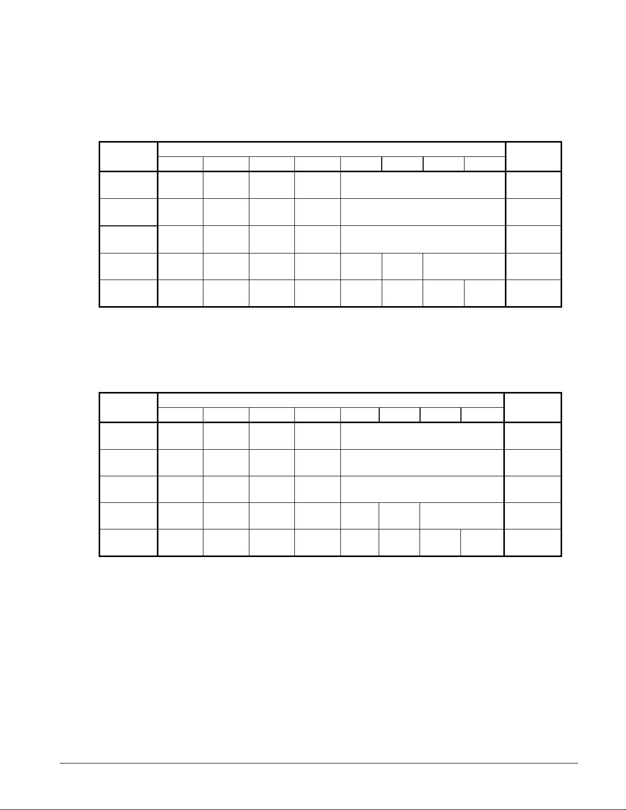
Table 4, Spring Isolator Locations, Aluminum Fin
Mounting hole dimensions are on the unit dimension drawings beginning on page 18. The vibration isolators
are different for AGZ units with pump packages than those without. All isolators have two springs per housing
(C2PE).
AGZ-C
Size
030, 035, 040
045, 050, 055
060, 065, 070
075, 080, 090
100
110, 125, 130
140, 160, 180
190
M1 M2 M3 M4 M5 M6 M7 M8
1D-1350 1D-1350 1D-1350 1D-1350
Purple Purple Purple Purple
1D-1800 1D-1800 1D-1800 1D-1800
Green Green Green Green
1D-2400 1D-2400 1D-1800 1D-1800
Gray Gray Green Green
1D-1800 1D-1800 1D-1800 1D-1800 1D-1800 1D-1800
Green Green Green Green Green Green
1D-2400 1D-2400 1D-2400 1D-2400 1D-2400 1D-2400 1D-2400 1D-2400
Gray Gray Gray Gray Gray Gray Gray Gray
SPRING-FLEX ISOLATORS
NUMBERS
332320116
332320117
332320118
332320119
332320120
KIT
Table 5, Spring Isolator Locations, Copper Fin
Mounting hole dimensions are on the unit dimension drawings beginning on page 18. The vibration isolators
are different for AGZ units with pump packages than those without. All isolators have two springs per housing
(C2PE).
AGZ-C
Size
030, 035, 040
045, 050, 055
060, 065, 070
075, 080, 090
100
110, 125, 130
140, 160, 180
190
M1 M2 M3 M4 M5 M6 M7 M8
1D-1350 1D-1350 1D-1350 1D-1350
Purple Purple Purple Purple
1D-1800 1D-1800 1D-1800 1D-1800
Green Green Green Green
1D-2720 1D-2720 1D-2720 1D-2720
White White Gray Gray
1D-2720 1D-2720 1D-2720 1D-2720 1D-2720 1D-2720
Gray Gray Gray Gray Gray Gray
1D-2720 1D-2720 1D-2720 1D-2720 1D-2720 1D-2720 1D-2720 1D-2720
Gray Gray Gray Gray Gray Gray Gray Gray
SPRING-FLEX ISOLATORS
NUMBERS
332320116
332320117
332320121
332320122
332320120
KIT
IOMM AGZC Pump Pkg 7
Page 8

Pump Control
There are three possible pump control arrangements:
1. Single Pump/Single Control; the standard single digital output from the chiller’s
microprocessor control starts and stops the pump.
2. Dual Pump/Single Control; the standard single digital output controls the pumps. Pump
operation is automatically selected by an alternating relay arrangement. The panel has a
selector switch allowing selection of pump A, pump B, or automatic (using relays).
3. Dual Pump/Dual Control; an optional second chiller digital output must be supplied and
operation of the pumps is controlled by settings in the microprocessor as follows:
The pump output used is determined by the Evap Pump Control setpoint. This setting
allows the following configurations:
#A only – Pump A will always be used
#B only – Pump B will always be used
Auto – The primary pump is the one with the least run hours, the other is used as a
backup
#A Primary – Pump A is used normally, with pump B as a backup
#B Primary – Pump B is used normally, with pump A as a backup
Primary/Standby Pump Staging
The pump designated as primary will start first. If the evaporator state is START for a
time greater than the RECIRCULATE TIMEOUT setpoint and there is no flow, then the
primary pump will shut off and the standby pump will start. When the evaporator is in
the RUN state, if flow is lost for more than half of the FLOW PROOF setpoint value,
the primary pump will shut off and the standby pump will start. Once the standby pump
is started, the FLOW LOSS alarm logic will apply if flow cannot be established in the
evaporator START state, or if flow is lost in the EVAPORATOR RUN state.
Auto Control
If AUTO pump control is selected, the primary/standby logic above is still used. When
the evaporator is not in the RUN state, the run hours of the pumps will be compared.
The pump with the least hours will be designated as the primary at this time.
Freeze Protection
In installations where the unit is subject to sub-freezing temperatures, some method of
preventing pipe and component freezing and subsequent damage must be employed.
The pump package has an outdoor air thermostat (TH1) that will start the pump at 40F
to help prevent freeze up.
If the chiller is valved out of the building circulation system during freezing
temperatures, a valved bypass must be installed between the supply and return lines, on
the pump side of the chiller isolation valves.
If operation of the chilled water pump during freezing weather is not desired, one or
more of the following strategies must be employed:
4. Drain the portion of the system subject to freezing and cap with a nitrogen charge.
If the system will be drained, the pump(s) and the interconnecting piping also have
to be drained. A drain plug is provided at the very bottom of the pump housing and
at the bottom of the evaporator barrel or package piping. Open the appropriate
vents to assist in draining. A nitrogen head is recommended to decrease corrosion
in the drained portion of the piping
8 IOMM AGZC Pump Pkg
Page 9

5. Heat trace all outdoor piping and components. If the system is to have field-installed
heat tracing, the factory pipe insulation will have to be removed and replaced after the
installation of the tracing.
6. Add sufficient anti-freeze to prevent freezing. If an anti-freeze solution is to be used,
additional anti-freeze must be added to protect the water in the pump package.
Adding of a concentration of a glycol anti-freeze with a freeze point 10 degrees F below
the lowest expected outdoor temperature will result in decreased capacity and increased
pressure drop in the chiller. AGZ units can be selected to provide the required capacity
with the fluid specified, water or antifreeze.
Note: Do not use automotive grade antifreezes as they contain inhibitors harmful to
chilled water systems. Use only glycols specifically designated for use in building
cooling systems.
IOMM AGZC Pump Pkg 9
Page 10
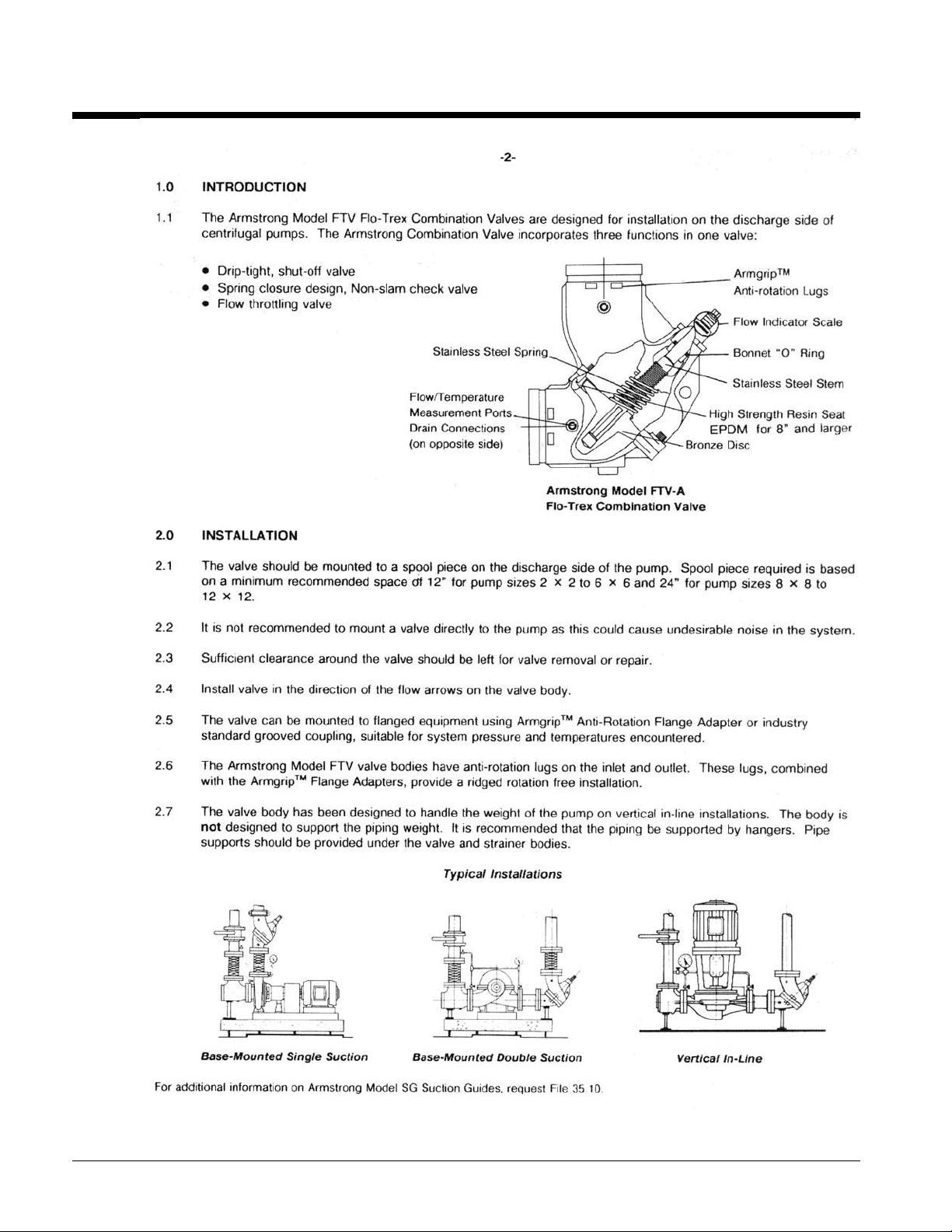
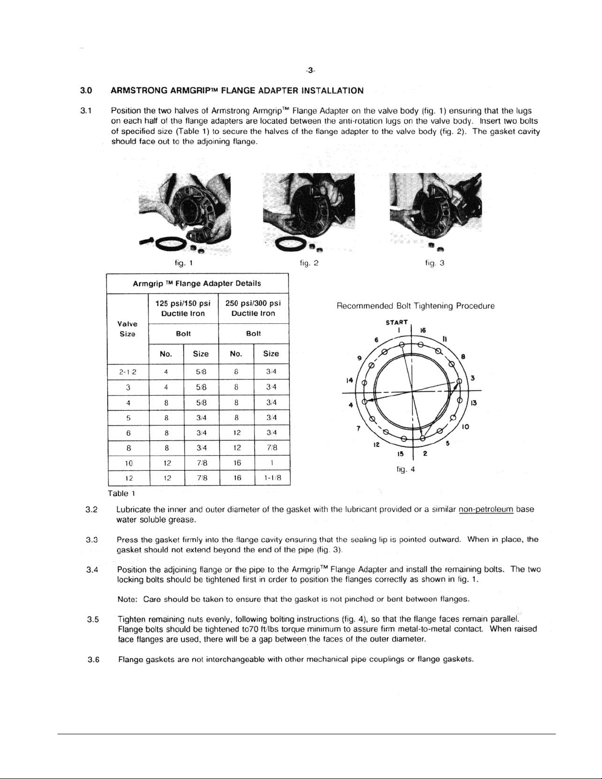
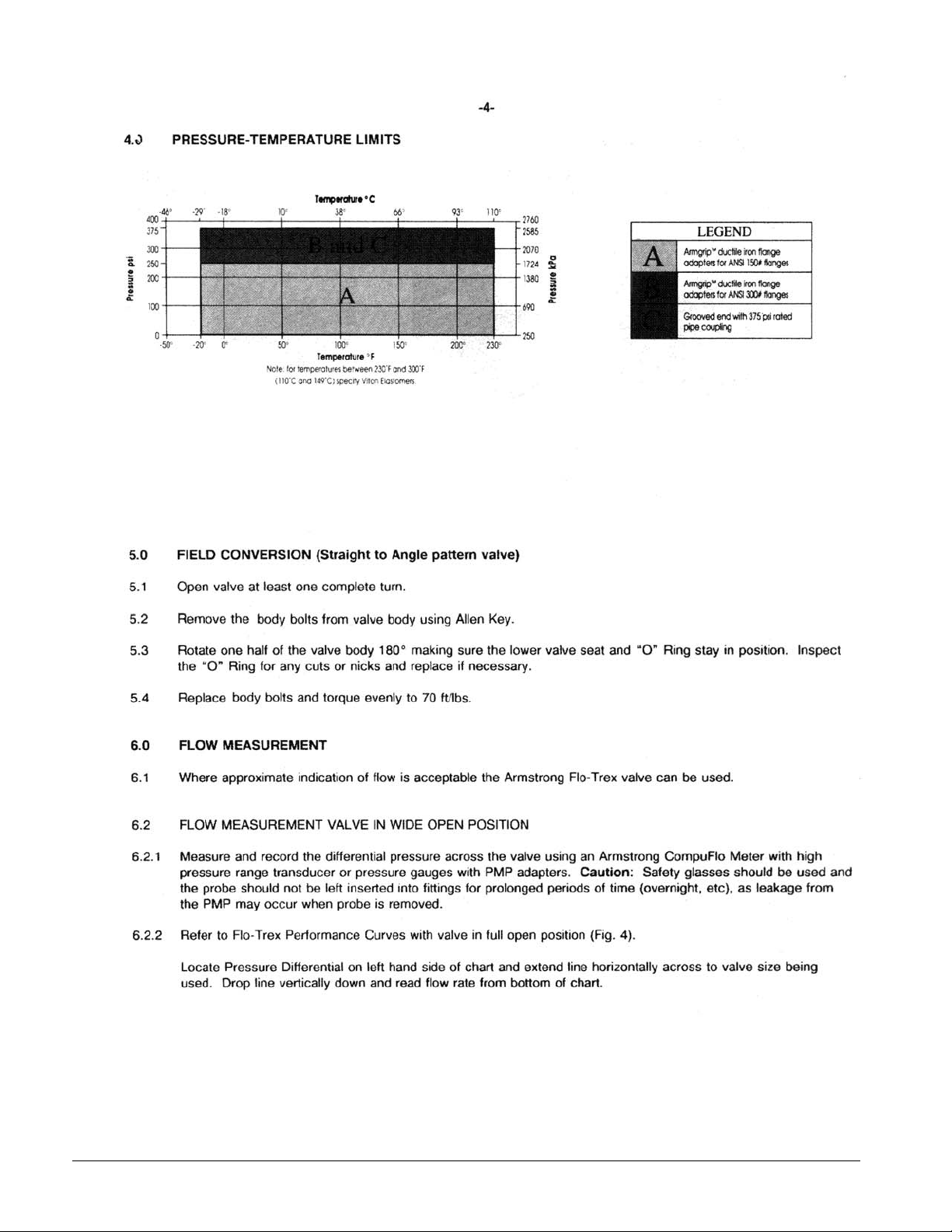
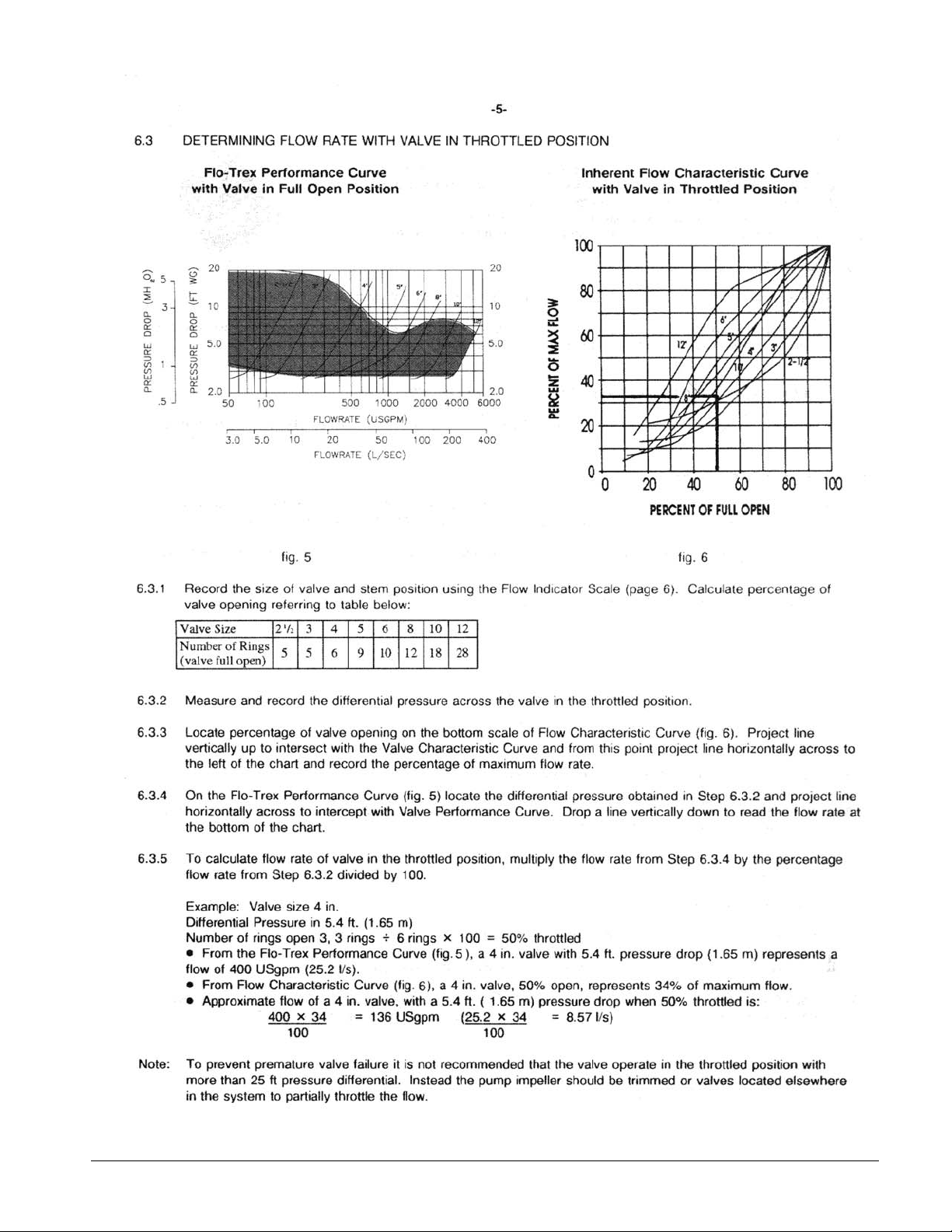
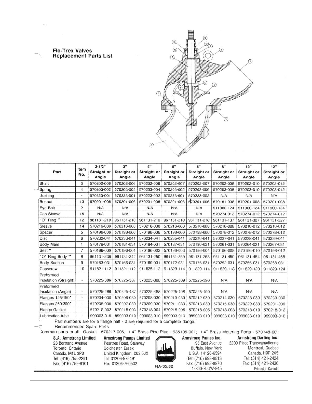
Triple-Duty Valve
10 IOMM AGZC Pump Pkg
Page 11
IOMM AGZC Pump Pkg 11
Page 12
12 IOMM AGZC Pump Pkg
Page 13
IOMM AGZC Pump Pkg 13
Page 14

14 IOMM AGZC Pump Pkg
Page 15
IOMM AGZC Pump Pkg 15
Page 16
Component Location
Table 6 ,Standard Pump Package Components
Commponent AGZ 030-070 AGZ 075-130 AGZ 140-190
Strainer Y Strainer w/ B-D Valve Inlet Guide Inlet Guide (1)
Suction S-O Valve 1 per Pump 1 per Pump 1 per Pump
Discharge Check 1 per Pump 1 per Pump 1 per Pump
Discharge S-O Valve 1 per Pump 1 per Pump 1 per Pump
Flow Switch 1 per Unit 1 per Unit 1 per Unit
Triple-Duty Valve 1 per Unit 1 per Unit 1 per Unit
Pump(s) 1 or 2 1 or 2 1 or 2
Control Panel Mounted on the pump package base, not shown below for clarity.
NOTES:
1. Field Installed
2. All cold surfaces are insulated.
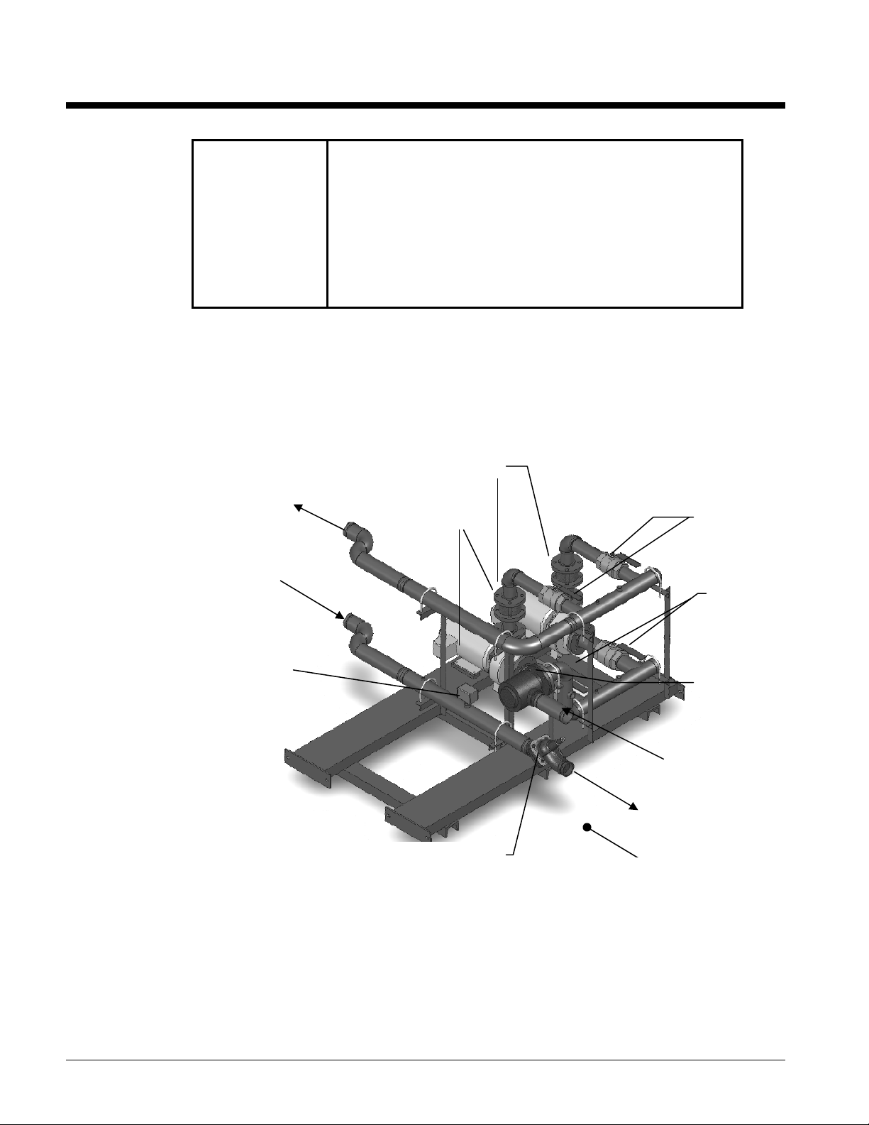
Figure 1, Standard Components, AGZ 110C to 130C, Dual Pumps
Control panel not shown for clarity.
To Evaporator
(Factory)
From Evaporator
(Factory)
Flow Switch
Discharge Check
Pumps
Triple Duty Valve
Discharge S O
Valves (2)
Suction S O
Valves (2)
Inlet Guide
(Strainer)
System Inlet Conn.
System Outlet Conn.
BACK OF
UNIT
16 IOMM AGZC Pump Pkg
Page 17
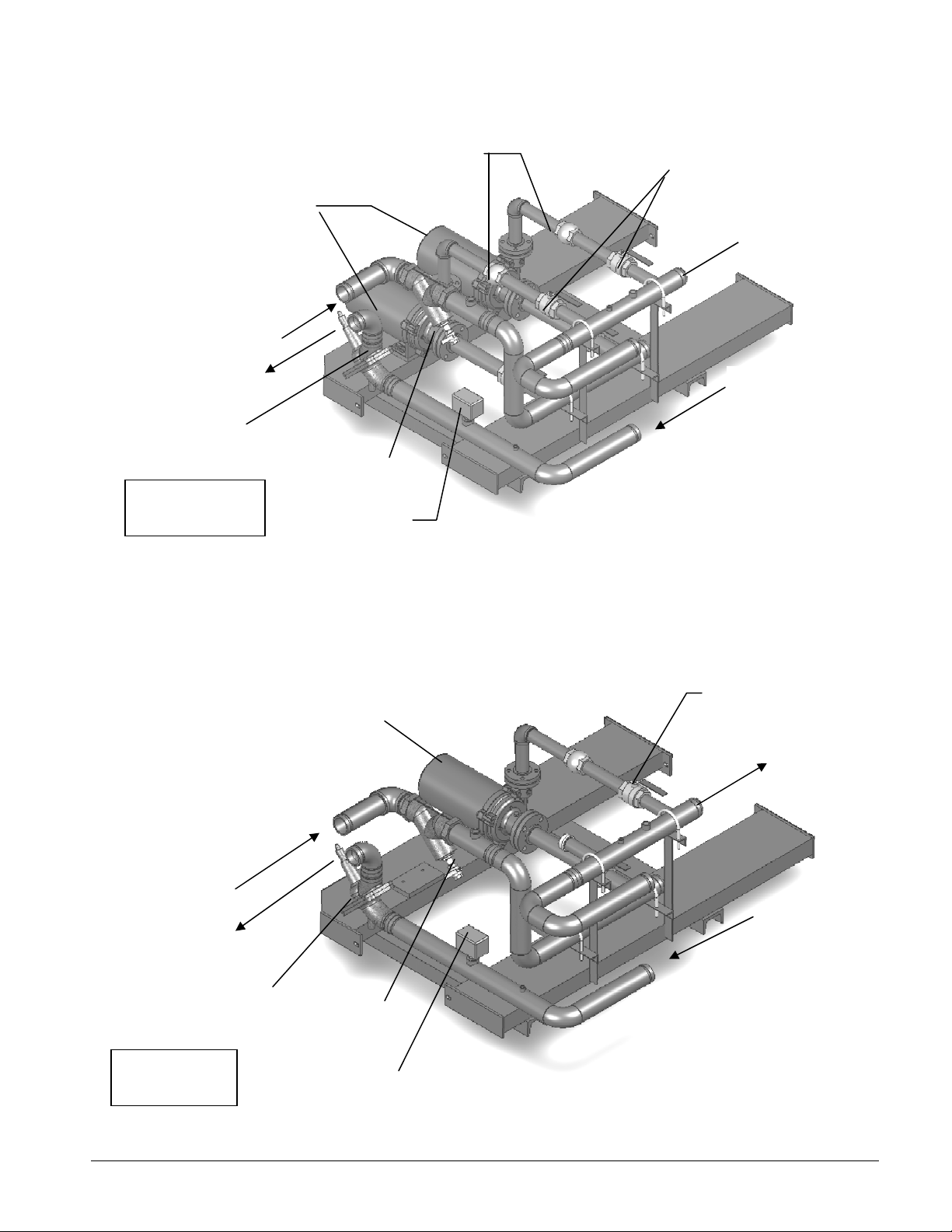
Figure 2, Standard Components, AGZ 030C to 070C, Dual Pumps
(2)
Control panel not shown for clarity.
Pumps
System Inlet
System Outlet
Triple-Duty
Outlet Valve
LEFT SIDE
Of UNIT
Discharge Check Valves
Y- St r ai n e r
Flow Switch
Figure 3, Standard Components, AGZ 030C to 070C, Single Pump
Control panel not shown for clarity.
Shut-Off
Va l ve s
To Evaporator
From
Evaporator
System Inlet
System Outlet
Triple-Duty
Outlet Valve
LEFT SIDE
Of UNIT
Shut Off Valve
Pump
To Evaporator
From
Evaporator
Y- St r ai n e r
Flow Switch
IOMM AGZC Pump Pkg 17
Page 18
Dimensions
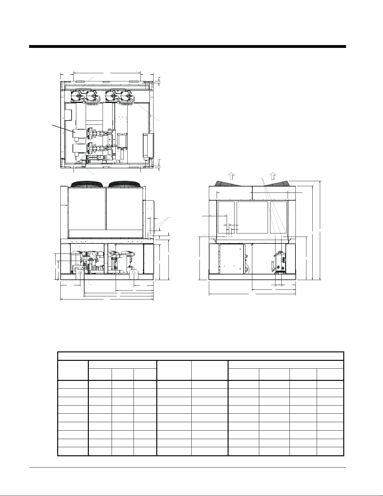
Figure 4, AGZ 030C to 070C Dimensions with Pump Package
ISOLATOR MOUNTING HOLE LOCATIONS ON BOTTOM SURFACE OF UNIT BASE
13.3
L3
67.8
COMPRESSOR
CIRCUIT #2
M1M3
13.3
L1
2.0
COMPRESSOR
CIRCUIT #1
2.0
NOTE:
1. DUE TO VARIATIONS IN PUMP SIZES, OPERATING WEIGHT WITH WATER IS
APPROXIMATE AND MAY INCREASE UP TO 5%
CG
EVAP
D
B
L2
M2M4
POWER
3.4
CONNECTIONS
OPPOSITE SIDE
OF CONTROL BOX
5.0
2.0
4.0
18.0
FIELD CONTROL
CONNECTION
POWER ENTRY POINT
.875 KNOCK OUTS
FRONT OR SIDE
CONTROL BOX WIDTH
CONTROL
PAN EL
2.5
2.5
8.0
REF.
94.9
100.2
CG
40.7
Y
L1
19.9
L2
Z
43.7
PUMP
COMTROL
PAN EL
88.0
6.4
14.4
X
ALL DIMENSIONS ARE IN DECIMAL INCHES
SCALE
*331779021001*
NONE
43.7
L4
EVAP PIPING
CONNECTIONS
EVAP WATER
INLET
A
C
19.9
EVAP WATER
L3
L4
OUTLET
94.3
NOTES:
1. The dimension drawing depicts the dual-pump option; a single pump is also available. Water connections are
in the same location with either arrangement.
2. See following page for additional dimensions and pump information.
3. Due to variations in pump sizes, operating weight with water is approximate, and may increase up to 5%. The
mounting weights are shown on page 5.
AGZ-C, 4-FAN UNIT, WEIGHTS AND CG (with PUMPS)
AGZ-C
MODEL
030C 43.4 37.8 45.0 4020 4035 1101 1072 936 911
035C 43.7 37.7 44.9 4070 4090 1112 1095 939 925
040C 43.8 37.9 45.0 4185 4205 1134 1122 970 959
045C 45.1 40.0 45.1 4310 4335 1133 1189 971 1018
050C 44.2 38.7 45.1 4435 4465 1187 1198 1020 1030
055C 44.7 38.8 44.3 4375 4405 1191 1229 962 993
060C 46.1 38.2 44.3 4640 4690 1222 1343 989 1087
065C 46.2 38.2 44.6 4670 4725 1213 1342 1004 1111
070C 42.6 36.6 47.3 5225 5280 1341 1255 1358 1271
CG LOCATION (in.) LIFTING WEIGHT BY CORNER (lbs))
X Y Z
SHIPPING
WEIGHT (lbs)
OPERATING
WEIGHT (lbs)
L1 L2 L3 L4
18 IOMM AGZC Pump Pkg
Page 19

EVAP
WATER
CONNECTION
Figure 5, AGZ 075C to 100C Dimensions with Pump Package
ISOLATOR MOUNTING HOLE LOCATIONS ON BOTTOM SURFACE OF UNIT BASE
12.4 12.4110.1
L3
EVAP
L4
TOP VIEW
M1M3
L1
2.0
COMPRESSOR
CIRCUIT #2
EVAP. WATER
INLET
COMPRESSOR
CIRCUIT #1
B
C
L2
M2M4
2.0
EVAP. WATER
OUTLET
BACK VIEW
POWER ENTRY POINT
.875 KNOCK OUTS
FRONT AND SIDE
A
49.5
43.7
8.0
REF.
24.0
POWER
CONNECTIONS
OPPOSITE SIDE
OF CONTROL BOX
2.0
CG
5.0
EVAP
L3
L4
134.9
L1
24.0
L2
Z
3.4
4.0
40.7
FIELD CONTROL
Y
18.0
CONNECTION
43.7
SIDE VIEW
CONTROL BOX WIDTH
CONTROL
BOX
2.5
2.5
CG
PUMP
CONTROL
PAN EL
FRONT VIEW
88.0
6.4 14.4
X
NOTES:
1. The dimension drawing depicts the optional dual-pump arrangement, a single pump is standard.
2. See following page for additional dimensions and pump information.
3. Due to variations in pump sizes, operating weight with water is approximate, and may increase up to 5%. The
mounting weights are shown on page 5.
AGZ-C, 6-FAN UNIT, WEIGHTS AND CG (with PUMPS)
CG LOCATION (in.) LIFTING WEIGHT BY CORNER (lbs) AGZ-C
MODEL X Y Z
SHIPPING
WEIGHT
(lbs)
OPERATING
WEIGHT
(lbs)
L1 L2 L3 L4
95.0
100.2
075C 47.2 38.1 61.0 6640 6690 1769 2044 1312 1516
080C 47.3 39.7 59.3 6720 6775 1847 2143 1264 1466
090C 47.2 40.0 59.8 6595 6660 1800 2075 1262 1457
100C 47.4 39.6 60.7 6730 6795 1797 2093 1311 1529
IOMM AGZC Pump Pkg 19
Page 20

C
A
Figure 6, AGZ 110C to 130C Dimensions with Pump Package
ISOLATOR MOUNTING HOLE LOCATIONS ON BOTTOM SURFACE OF UNIT BASE
25.2 67.8 67.7 12.4
L1
EVAP
L4
EVAP
WATER
ONNECTIONS
M6 M4 M2
TOP VIEW
M1M3M5
L1L3
2.0
COMPRESSOR
CIRCUIT #2
EVAP. WATER
COMPRESSOR
CIRCUIT #1
L2
INLET
2.0
B
C
EVAP. WATER
OUTLET
BACK VIEW
CONTROL BOX WIDTH
POWER ENTRY POINTS
.875 KNOCK OUTS
FRONT OR SIDE
50.0
REF.
8.0
CG
L3
L4
24.0 24.0
NOTES:
1. DUE TO VARIATIONS IN PUMP SIZES, OPERATING WEIGHT WITH WATER
SIDE VIEW
173.1
Z
IS AP PROXIMATE AND MAY INCREASE UP TO 5%.
POWER
CONNECTIONS
OPPOSITE SIDE
40.7
3.4
4.0
Y
OF CONTROL BOX
5.0
FIELD CONTROL
CONNECTIONS
43.7
2.0
L1
L2
PUMP
CONTROL
PANE L
CONTROL
BOX
2.518.1
CG
2.5
6.4 14.4
SCALE
*331779023001*
NONE
X
88.0
FRONT VIEW
ALL DIMENSIONS ARE IN DECIMAL INCHES
43.7
NOTES:
1. The dimension drawing depicts the optional dual-pump arrangement, a single pump is standard.
2. See following page for additional dimensions and pump information.
3. Due to variations in pump sizes, operating weight with water is approximate, and may increase up to 5%. The
mounting weights are shown on page 5.
AGZ-C, 8-FAN UNIT, WEIGHTS AND CG (with PUMPS)
AGZ-C
MODEL
CG LOCATION (in.) LIFTING WEIGHT BY CORNER (lbs)
X Y Z
SHIPPING
WEIGHT
(lbs)
110C 46.2 38.6 79.0 8580 8650 2284 2522 1794 1981
OPERATING
WEIGHT
(lbs)
L1 L2 L3 L4
95.0
100.2
125C 45.8 39.7 79.2 8720 8800 2337 2534 1847 2002
130C 46.1 40.7 78.3 8850 8945 2386 2624 1829 2012
20 IOMM AGZC Pump Pkg
Page 21

Figure 7, AGZ 140C to 180C Dimensions with Pump Package
2
A
ISOLATOR MOUNTING HOLE LOCATIONS ON BOTTOM SURFACE OF UNIT BASE
M7
34.17 72.80
L5
M5
L3
81.1 67.7 12.4
M3
M1
L1
2.0
COMPRESSOR
CIRCUIT #2
COMPRESSOR
CIRCUIT #1
31.97
L6
M8
85.89
8"
VICTAULIC
CONNECTION
L5
L6
15.50
NOTE:
1. DUE TO VARIATIONS IN PUMP SIZES, OPERATING WEIGHT WITH
104.2
17.00
EVAP
WATER
OUTLET
NOTES:
1. The dimension drawing depicts the optional dual-pump arrangement, a single pump is standard.
2. See following page for additional dimensions and pump information.
3. Due to variations in pump sizes, operating weight with water is approximate, and may increase up to 5%. The
mounting weights are shown on page 5.
EVAP
L4
M6
TOP VIEW
CG
M4
Y
EVAP
L3
L4
268.0
SIDE VIEW
WATER IS APPROXIMATE AND MAY INCREASE UP TO 5%.
L2
M2
2.00
L1
L2
Z
24.0
2.0
POWER CONNECTIONS
OPPOSITE SIDE OF
CONTROL BOX
3.40
FIELD CONTROL
CONNECTIONS
5.00
4.80
41.62
44.0
WATER
INLET
POWER ENTRY POINTS
.875 KNOCK OUTS
FRONT OR SIDE
CONTROL
PAN EL
2.511.8
2.5
PUMP
CONTROL
PANE L
88.0
FRONT VIEW
43.04
BACK VIEW
CG
6.5 6.6
X
ALL DIMENSIONS ARE IN DECIMAL INCHES
SCALE
*331779024001*
NONE
95.0
44.0
100.
AGZ-C, 10-FAN UNIT, WEIGHTS AND CG (with PUMPS)
AGZ-C
MODEL
CG LOCATION (in.) LIFTING WEIGHT BY CORNER (lbs)
X Y Z
SHIPPING
WEIGHT
(lbs)
OPERATING
WEIGHT (lbs)
L1 L2 L3 L4 L5 L6
140C 44.7 39.6 121.7 12580 13062 2784 2872 1964 2026 1444.4 1489.8
160C 44.1 37.4 123.3 12610 13092 2776 2794 2000 2013 1508.2 1517.8
180C 44.4 35.2 122.7 12731 13213 2805 2859 2004 2043 1495.9 1524.7
IOMM AGZC Pump Pkg 21
Page 22

Figure 8, AGZ 190C Dimensions with Pump Package
A
W
(
(
)
ISOLATOR MOUNTING HOLE LOCATIONS ON BOTTOM SURFACE OF UNIT BASE
119. 272.834.2
L5
L6
17.0
L3
L4
TOP VIEW
Y
EVAP
32.1
L7
L8
8"
VICTAULIC
CONNECTION
124.25
M1M3M5M7
12.4067.7
L1
2.0
COMPRESSOR
CIRCUIT #2
COMPRESSOR
CIRCUIT #1
L2
2.00
2.0
M2M4M6M8
POWER CONNECTIONS
OPPOSITE SIDE OF
3.40
5.00
41.62
CONTROL BOX
4.80
FIELD CONTROL
CONNECTIONS
11. 8
44.00
EVAP
WATER
INLET
POWER ENTRY POINTS
.875 KNOCK OUTS
FRONT OR SIDE
2.50
PUMP
CONTROL
PANE L
CONTROL
PAN EL
2.50
CG
43.04
BACK VIEW
44.0
95.0
100.2
6.5
X
88.00
*R331779025001*
EVAP
WATER
OUTLET
306.19
SIDE VIEW
24.085.2392.7788.6815.50
Z
ALL DIMENSIONS ARE IN DECIMAL INCHES
SCALE
NONE
NOTES:
1. The dimension drawing depicts the optional dual-pump arrangement, a single pump is standard.
2. Due to variations in pump sizes, operating weight with water is approximate, and may increase up to 5%.
AGZ-C, 12-FAN UNIT, WEIGHTS AND CG (with PUMPS)
AGS-C
MODEL
CG LOCATION (in.) LIFTING WEIGHT BY CORNER
SHIPPING
WEIGHT
X Y Z
lbs)
OPERATING
WEIGHT
lbs
L1 L2 L3 L4 L5 L6 L7 L8
190C 44.5 36.8 142.7 14352 14834 2098 2147 1889 1934 1661 1700 1445 1478
6.6
FRONT VIE
22 IOMM AGZC Pump Pkg
Page 23

Pump Curves
The impeller of each pump is cut to meet the project’s design flow and head, and it is not practical to include
so many of them in this manual. However, a close approximation of the job’s specific pump can be made as
follows:
1. Using the pump nameplate as a reference, find the generic pump curve in this section.
2. Using the project’s design information, find the system design flow and head
3. Mark this flow and head on the pump curve and using the point as a reference point, draw in curve
parallel to the curve above and below it.
4. For example, if the design conditions were 90 gpm at a 90 ft. head, the point would be as shown below.
Draw a curve through it and parallel to the 5.50 in. and the 5.00 in. impeller curves.
Figure 9, Series 4270, 2x1.5x5.5, 3600 RPM
Hea d (m ) ft
(36.6) 120
(27.4) 90
(18.3) 60
(9. 1) 30
(0. 0) 0
Wa t e r, sg = 1 . 00
5.50 in
5.00 in
4.50 in
4.00 in
3.50 in
0
0.00
3600 RPM
43
55
62
67
70
71
71
71
70
67
62
55
5 hp
3 hp
2 hp
N
P
0.5 hp
0.75 hp
1 hp
S
H
r
NPSHr
30
1.89
60
3.79
1.5 hp
90
5.68
120
7.57
150
9.46
(usgpm)
(lp s)
Fl o w
CURVE NO.
PT32-1-7-3600
SERIES
4270
SIZE
2x1.5x5.5
RPM
3600
BHP based on
sho wn Flu id 's sp . g r.
4270
All Rating s
A
V
A
I
L
A
B
I
L
Design Operating Point
IOMM AGZC Pump Pkg 23
Page 24

Figure 10, Series 4280, 3x1.5x6, 3600 RPM
Head (m) ft
(45.7)
(36.6)
(27.4) 90
(18.3) 60
(9.1) 30
(0.0) 0
Water, sg= 1.00
150
120
0
0.00
6.19 in
5.63 in
5.25 in
4.88 in
4.50 in
N
P
S
H
r
NPSHr
60
3.79
49
58
65
69
71
2 hp
120
7.57
CURVE NO.
3600 RPM
PT49-2-0-3600
SERIES
71
71
7272
3 hp
69
5 hp
65
58
49%
7.5 hp
15 hp
10 hp
4030
4280
SIZE
3x1.5x6
RPM
3600
BHP based on
shown Fluid's sp. gr.
4030
All Ratings
4280
All Ratings
A
(lps)
Flow
V
A
I
L
A
B
I
L
180
11. 36
240
15.14
(usgpm)
Figure 11, Series 4280, 3x1.5x6, 1800 RPM
Head (m) ft
(12.2) 40
(9.8) 32
(7.3) 24
(4.9) 16
(2.4) 8
(0.0) 0
Water, sg= 1.00
0
0.00
6.19 in
5.63 in
5.25 in
4.88 in
4.50 in
N
P
S
H
r
NPSHr
50
30
1.89
60
67
71
72
0.25 hp
60
3.79
73
0.333 hp
72
0.5 hp
90
5.68
71
0.75 hp
1800 RPM
67
60
1 hp
120
7.57
1.5 hp
(usgpm)
(lps)
Flow
CURVE NO.
PT48-2-0-1800
SERIES
4030
4280
SIZE
3x1.5x6
RPM
1800
BHP based on
shown Fluid's sp. gr.
4030
All Ratings
4280
All Ratings
A
V
A
I
L
A
B
I
L
24 IOMM AGZC Pump Pkg
Page 25

4
4
C
3
R
AVAILAB
I
L
S
S
1
4
4
C
3
R
AVAIL
A
B
I
L
S
S
3
Figure 12, Series 4280, 3x1.5x8, 1800 RPM
Head (m) ft
(19.5) 64
(14.6) 48
(9.8) 32
(4.9) 16
(0.0) 0
Water, sg= 1.00
8.19 in
7.50 in
7.00 in
6.50 in
6.00 in
0
0.00
N
P
S
H
r
NPSHr
36
49
58
64
67
69
1 hp
0.75 hp
40
2.52
80
5.05
69
49%
1.5 hp
120
7.57
URVE NO.
1800 RPM
69
67
64
58
5 hp
PT50-1-0-1800
ERIES
030
280
IZE
x1.5x8
3 hp
PM
800
2 hp
BHP based on
shown Fluid's sp. gr.
4030
All Ratings
4280
All Ratings
160
10.09
(usgpm)
(lps)
Flow
Figure 13, Series 4280, 3x2x6, 3600 RPM
Head (m) ft
(36.6)
(27.4) 90
(18.3) 60
(9.1) 30
Water, sg= 1.00
120
(0.0) 0
6.19 in
5.63 in
5.25 in
4.88 in
4.50 in
0
0.00
49
59
66
N
P
S
H
r
NPSHr
80
5.05
160
10.09
URVE NO.
71
74
74
74
3600 RPM
71
66
15 hp
PT63-1-0-3600
ERIES
030
280
IZE
x2x6
PM
600
BHP based on
4030
49%
10 hp
59%
7.5 hp
shown Fluid's sp. gr.
5 hp
All Ratings
3 hp
240
15.14
320
20.19
(usgpm)
(lps)
4280
All Ratings
Flow
IOMM AGZC Pump Pkg 25
Page 26

Figure 14, Series 4280, 3x2x6, 1800 RPM
4
4
C
3
R
S
S
1
4
4
C
3
R
S
S
1
Head (m) ft
6.19 in
37
49
59
67
(9.8) 32
5.63 in
(7.3) 24
5.25 in
4.88 in
4.50 in
(4.9) 16
(2.4) 8
(0.0) 0
Water, sg= 1.00
0
0.00
N
P
S
H
NPSHr
r
40
2.52
80
5.05
URVE NO.
1800 RPM
72
74
75
74
72
67
1.5 hp
59%
PT62-1-0-1800
ERIES
030
280
IZE
x2x6
PM
800
1 hp
49%
0.75 hp
BHP based on
shown Fluid's sp. gr.
4030
All Ratings
0.5 hp
0.333 hp
120
7.57
160
10.09
(usgpm)
(lps)
Flow
A
V
A
I
L
A
B
I
L
4280
All Ratings
Figure 15, Series 4280, 3x2x8, 1800 RPM
Head (m) ft
(18.3) 60
(14.6) 48
(11.0) 36
(7.3) 24
(3.7) 12
Water, sg= 1.00
(0.0) 0
0
0.00
8.13 in
7.63 in
7.13 in
6.63 in
5.88 in
N
P
S
H
r
NPSHr
36
50
60
67
72
1 hp
60
3.79
120
7.57
74
1.5 hp
74
2 hp
180
11. 36
URVE NO.
1800 RPM
74
72
67
60
5 hp
PT64-1-0-1800
ERIES
030
280
IZE
x2x8
PM
3 hp
800
BHP based on
shown Fluid's sp. gr.
4030
All Ratings
4280
All Ratings
A
(lps)
Flow
V
A
I
L
A
B
I
L
240
15.14
(usgpm)
26 IOMM AGZC Pump Pkg
Page 27

Figure 16, Series 4280, 3x2.5x8, 1800 RPM
4
4
3
R
S
S
1
4
4
C
3
R
A
V
AIL
ABI
L
S
S
3
Head (m) ft
(18.3) 60
(14.6) 48
8.19 in
7.38 in
6.75 in
40
5353%
63
70
74
76
76
CURVE NO.
1800 RPM
PT56-1-0-1800
ERIES
76
74
70
63
7.5 hp
030
280
IZE
x2.5x8
(11.0) 36
6.13 in
5.50 in
(7.3) 24
2 hp
1.5 hp
240
15.14
(3.7) 12
(0.0) 0
Water, sg= 1.00
0
0.00
N
P
S
NPSHr
H
r
80
5.05
1 hp
160
10.09
Figure 17, Series 4280, 3x2.5x6, 3600 RPM
Head (m) ft
150
(45.7)
(36.6)
(27.4) 90
120
6.19 in
5.63 in
5.25 in
4.88 in
4.50 in
39
52
62
69
74
3 hp
76
320
20.19
76
5 hp
76
PM
800
BHP based on
shown Fluid's sp. gr.
4030
All Ratings
4280
All Ratings
A
(lps)
Flow
V
A
I
L
A
B
I
L
400
25.24
(usgpm)
URVE NO.
3600 RPM
PT55-1-0-3600
ERIES
030
280
IZE
74
69
62
x2.5x6
PM
600
(18.3) 60
(9.1) 30
15 hp
10 hp
N
P
S
H
NPSHr
r
3 hp
7.5 hp
5 hp
BHP based on
shown Fluid's sp. gr.
4030
All Ratings
4280
All Ratings
(0.0) 0
0
0.00
100
6.31
200
12.62
300
18.93
400
25.24
500
31.54
(usgpm)
(lps)
Flow
Water, sg= 1.00
IOMM AGZC Pump Pkg 27
Page 28

Figure 18, Series 4280, 3x2.5x6, 1800 RPM
Head (m) ft
6.19 in
(9.8) 32
5.63 in
5.25 in
37
51
61
68
72
75
(7.3) 24
4.88 in
4.50 in
(4.9) 16
(2.4) 8
(0.0) 0
Water, sg= 1.00
0
0.00
N
P
NPSHr
S
H
r
60
3.79
0.333 hp
120
7.57
0.5 hp
75
180
11.36
75
51%
0.75 hp
72
68
1 hp
1800 RPM
61
2 hp
1.5 hp
240
15.14
(usgpm)
CURVE NO.
PT54-1-0-1800
BHP based on
shown Fluid's sp. gr.
A
V
A
I
(lps)
L
A
Flow
B
I
L
SERIES
4030
4280
SIZE
3x2.5x6
RPM
1800
4030
All Ratings
4280
All Ratings
Figure 19, Series 4382, 3x3x8, 1800 RPM
Head (m) ft
8.19 in
36
48
57
63
67
(19.5) 64
7.50 in
7.00 in
(14.6) 48
6.50 in
6.00 in
(9.8) 32
(4.9) 16
(0.0) 0
Water, sg= 1.00
0
0.00
N
P
S
H
NPSHr
r
40
2.52
80
5.05
0.75 hp
7.57
1 hp
120
69
48%
69
1.5 hp
69
2 hp
160
10.09
1800 RPM
67
63
3 hp
12.62
200
CURVE NO.
PT30-1-0-1800
SERIES
4302
4382
SIZE
57
5 hp
3x3x8
RPM
1800
BHP based on
shown Fluid's sp. gr.
4302
All Ratings
4382
All Ratings
A
(lps)
Flow
V
A
I
L
A
B
I
L
(usgpm)
28 IOMM AGZC Pump Pkg
Page 29

Figure 20, Series 4280, 4x3x6, 3600 RPM
4
4
4
R
S
S
3
4
4
4
R
S
S
1
Head (m) ft
(45.7)
(36.6)
(27.4) 90
(18.3) 60
150
120
6.19 in
5.63 in
5.25 in
4.88 in
4.50 in
35
49
61
71
77
CURVE NO.
3600 RPM
PT78-1-0-3600
ERIES
030
82
83
82
77
71
30 hp
25 hp
20 hp
15 hp
280
IZE
x3x6
PM
600
BHP based on
shown Fluid's sp. gr.
0
0.00
N
P
S
H
NPSHr
r
160
10.09
320
20.19
480
30.28
(9.1) 30
(0.0) 0
Water, sg= 1.00
Figure 21, Series 4280, 4x3x6, 1800 RPM
Head (m) ft
(9.8) 32
(7.3) 24
(4.9) 16
Water, sg= 1.00
(2.4) 8
(0.0) 0
0
0.00
6.19 in
5.63 in
5.25 in
4.88 in
4.50 in
N
P
S
H
r
NPSHr
35
80
5.05
49
61
71
77
160
10.09
5 hp
82
240
15.14
7.5 hp
1 hp
0.75 hp
10 hp
83
640
40.38
82
1.5 hp
320
20.19
800
50.47
1800 RPM
77
71
3 hp
2 hp
25.24
400
(usgpm)
(lps)
Flow
5 hp
(usgpm)
(lps)
Flow
4030
All Ratings
4280
All Ratings
A
V
A
I
L
A
B
I
L
CURVE NO.
PT78-1-0-1800
ERIES
030
280
IZE
x3x6
PM
800
BHP based on
shown Fluid's sp. gr.
4030
All Ratings
4280
All Ratings
IOMM AGZC Pump Pkg 29
Page 30

Figure 22, Series 4382, 4x4x10, 1800 RPM
R
R
Head (m) ft
(30.5)
(24.4) 80
10.16 in
100
9.38 in
8.75 in
8.13 in
5441
64
70
73
75
CURVE NO.
1800 RPM
75
75
73
70
64
15 hp
PT66-2-0-1800
SERIES
4302
4382
SIZE
4x4x10
(18.3) 60
7.50 in
(12.2) 40
(6.1) 20
(0.0) 0
Water, sg= 1.00
0
0.00
N
P
S
H
NPSHr
r
80
5.05
160
10.09
2 hp
15.14
Figure 23, Series 4382, 6x6x6, 3600 RPM
Head (m) ft
150
(45.7)
(36.6)
(27.4) 90
120
6.19 in
5.63 in
5.25 in
4.88 in
4.50 in
42
55
66
74
79
82
(18.3) 60
0
0.00
N
P
S
NPSHr
H
r
200
12.62
400
25.24
37.85
(9.1) 30
(0.0) 0
Water, sg= 1.00
3 hp
240
600
83
5 hp
5 hp
82
7.5 hp
20.19
10 hp
50.47
320
79
800
7.5 hp
66%
15 hp
74
20 hp
10 hp
400
(usgpm)
25.24
3600 RPM
25 hp
1000
63.09
(usgpm)
shown Fluid's sp. gr.
A
V
A
I
(lps)
L
A
Flow
B
I
L
PT86-1-0-3600
shown Fluid's sp. gr.
A
V
A
I
(lps)
L
A
Flow
B
I
L
PM
1800
BHP based on
4302
All Ratings
4382
All Ratings
CURVE NO.
SERIES
4302
4382
SIZE
6x6x6
PM
3600
BHP based on
4302
All Ratings
4382
All Ratings
30 IOMM AGZC Pump Pkg
Page 31

Figure 24, Series 4382, 6x6x6, 1800 RPM
4
4
C
6
R
AVAILAB
I
L
S
S
1
4
4
C
6
R
AVAILAB
I
L
S
S
1
Head (m) ft
(9.8) 32
(7.3) 24
(4.9) 16
Water, sg= 1.00
(2.4) 8
(0.0) 0
6.19 in
5.63 in
5.25 in
4.88 in
4.50 in
0
0.00
44
58
68
76
80
83
N
P
NPSHr
S
H
r
100
6.31
200
12.62
0.5 hp
18.93
300
83
1 hp
0.75 hp
URVE NO.
1800 RPM
PT85-1-0-1800
ERIES
302
382
83
80
76
68
3 hp
2 hp
1.5 hp
IZE
x6x6
PM
800
BHP based on
shown Fluid's sp. gr.
4302
All Ratings
4382
All Ratings
400
25.24
500
31.54
(usgpm)
(lps)
Flow
Figure 25, Series 4382, 6x6x8, 1800 RPM
Head (m) ft
(18.3) 60
(14.6) 48
(11.0) 36
(7.3) 24
(3.7) 12
Water, sg= 1.00
(0.0) 0
8.19 in
7.50 in
7.00 in
6.50 in
6.00 in
0
0.00
35
48
59
67
73
N
P
NPSHr
S
H
r
160
10.09
320
20.19
30.28
77
480
3 hp
URVE NO.
1800 RPM
PT87-1-0-1800
ERIES
78
77
73
67
15 hp
302
382
IZE
x6x8
PM
5 hp
59%
7.5 hp
10 hp
800
BHP based on
shown Fluid's sp. gr.
4302
All Ratings
4382
All Ratings
640
40.38
800
50.47
(usgpm)
(lps)
Flow
IOMM AGZC Pump Pkg 31
Page 32

Figure 26, Series 4382, 6x6x10, 1800RPM
4
4
6
R
S
S
1
4
4
8
R
S
S
1
Head (m) ft
(30.5)
(24.4) 80
(18.3) 60
100
10.19 in
9.50 in
9.00 in
8.50 in
8.00 in
36
48
57
64
69
CURVE NO.
1800 RPM
71
72
71
69
64
57
15 hp
PT81-1-0-1800
ERIES
302
382
IZE
x6x10
PM
800
(12.2) 40
0
0.00
N
P
S
H
NPSHr
r
100
6.31
200
12.62
(6.1) 20
(0.0) 0
Water, sg= 1.00
Figure 27, Series 4382, 8x8x10, 1800RPM
Head (m) ft
(30.5)
(24.4) 80
(18.3) 60
100
10.19 in
9.50 in
9.00 in
8.50 in
8.00 in
56
68
76
81
3 hp
300
18.93
83
10 hp
7.5 hp
5 hp
BHP based on
shown Fluid's sp. gr.
4302
All Ratings
4382
All Ratings
A
(lps)
Flow
V
A
I
L
A
B
I
L
400
25.24
500
31.54
(usgpm)
CURVE NO.
1800 RPM
PT104-1-0-1800
ERIES
84
83
81
76
68
302
382
IZE
x8x10
PM
800
BHP based on
shown Fluid's sp. gr.
4302
All Ratings
4382
All Ratings
(12.2) 40
(6.1) 20
(0.0) 0
Water, sg= 1.00
0
0.00
56
25 hp
20 hp
15 hp
10 hp
5 hp
600
37.85
7.5 hp
800
50.47
1000
63.09
(usgpm)
(lps)
Flow
A
V
A
I
L
A
B
I
L
N
P
S
H
NPSHr
r
200
12.62
400
25.24
32 IOMM AGZC Pump Pkg
Page 33

Wiring Diagrams
Figure 28, Wiring Diagram with Dual Pumps/Single Control
IOMM AGZC Pump Pkg 33
Page 34

Figure 29, Wiring Diagram with Dual Pumps/Dual Control
C
\L1\PPU
\L2\PPU
DUAL CONTROL AND DUAL MOTOR
CBM
16 AWG
RED
8
15
16
17
18
1L1
1L2
1L3
14 AWG
GRN
16 AWG
YEL
16 AWG
WHT/YEL
16 AWG
YEL
16 AWG
WHT/YEL
12 AWG
BLK
T1
2.5
FU3
500VA
12
7
120VAC
FU6
FUSES INTEGRAL TO TRANS.
6
PUMP A
RUN
PUMP B
RUN
FU4
TS1-1
1L21L1
2.5
16 AWG
WHT
M1
A1 A2
M2
A1 A2
CLOSED <40F\POPEN
BLK
(MTD L-SIDE ENCL.)
1L1
1L2
1L3
4
4
43
TH1
>40\U+00B0F
BLK
PUMP A
PUMP B
INCOMING POWER
USTOMER SUPPLIED
3
3
(MTD L-SIDE ENCL.)
RUN SIGNAL
(120VAC)
RUN SIGNAL
(120VAC)
L1
L2
L3
PE
GND1 ENCL. DOOR
CR1
74
TS1-4 TS1-5
TH1
CR3
74
2
1
1
2
14 AWG
GRN
RED
TS1-3
GRN
16 AWG
GRN
1L1 1L2 1L3
TS1-2
G
}
See
Below
STANDARD LEGEND
WIRE NODE SYMBOL MAY
HAVE TERMINAL BLOCK
BENSHAW SUPPLIED
TERMINAL BLOCK
TERMINAL STRIP
POWER CONNECTION
PC BOARD TERMINALS
TWISTED PAIR
TWISTED SHIELDED PAIR
SHIELDED WIRE
FIELD WIRING
BLK
1L1 1L2 1L3
331480401rev0C
NOTES:
1
. TIGHTEN CONTROL TERMINALS TO 4.4 IN.\LBS (.5Nm)
2
. CUSTOMER CONNECTIONS SHALL USE COPPER WIRE
ONLY WITH A MINIMUM RATING OF 60C.
sheet 7
MSP1
CIRCUIT BREAKER
BLK
M1 CONTACTOR
13
14 222121436532
1L1A 1L2A 1L3A
1T1 1T2 1T3
M
MP MOTOR #1
43
31
44
TERMINATE TO
GND1 LUG
MOTOR GND
MSP2
CIRCUIT BREAKER
A1
X
A2
BLK
2L1A 2L2A 2L3A
M2 CONTACTOR
13
14 222121436532
TERMINATE TO
GND1 LUG
2T1 2T2 2T3
MOTOR GND
M
31
MP MOTOR #2
43
44
34 IOMM AGZC Pump Pkg
A1
A2
Page 35

Figure 30, Wiring Diagram with Single Pump/Single Control
Y
INCOMING POWER
CUSTOMER SUPPLIED
PE
RUN SIGNAL
(120VAC)
CBM
L1
L2
L3
14 AWG
GRN
GND1 ENCL. DOOR
16 AWG
CR1
74
TS1-4
TH1
1
RED
TS1-5
2
TB1
15
15
TB1
16
16
3
3
CLOSED <40F\POPEN
>40\U+00B0F
(MTD L-SIDE ENCL.)
1L1
1L2
1L3
16 AWG
GRN
12 AWG
BLK
T1
2.5
FU3
7
FU6
FUSES INTEGRAL TO TRANS.
6
TS1-3
16 AWG
YEL
16 AWG
WHT/YEL
500VA
12
120VAC
95 96
G
CR1
AB
SINGLE CONTROL AND SINGLE MOTOR
1L21L1
2.5
FU4
OL1
6A
PUMP
RUN
M1
A1 A2
1L1
1L2
1L3
16 AWG
WHT
4
4
BLK
PUMP A
14 AWG
GRN
1L1A 1L2A 1L3A
See
}
Below
STANDARD LEGEND
WIRE NODE SYMBOL MA
HAVE TERMINAL BLOCK
BENSHAW SUPPLIED
TERMINAL BLOCK
TERMINAL STRIP
POWER CONNECTION
PC BOARD TERMINALS
TWISTED PAIR
TWISTED SHIELDED PAIR
SHIELDED WIRE
FIELD WIRING
NOTES:
1
. TIGHTEN CONTROL TERMINALS
TO 4.4 in.\lbs (.5Nm)
. CUSTOMER CONNECTIONS SHALL
2
USE COPPER WIRE ONLY WITH A
MINIMUM RATING OF 60C
331480401rev0C
sheet 4
M1 CONTACTOR
13
14 222121436532
31
TERMINATE TO
GND1 LUG
MOTOR GND
M\L1\PPUMP MOTOR #1
IOMM AGZC Pump Pkg 35
Page 36

Electrical Data
Table 7, Unit Amp Draw
AGZ-C
SIZE
030
030
030
035
035
035
035
040
040
040
040
VOLTS
208 31.6 31.6 -- 31.6 31.6 -- 225 225 -- 225 225 -- 4 5.8 23.3 None -230 30.1 30.1 -- 30.1 30.1 -- 225 225 -- 225 225 -- 4 5.8 26.1 None -460 16.7 16.7 -- 16.7 16.7 -- 114 114 -- 114 114 -- 4 2.8 13.0 None -575 13.0 13.0 -- 13.0 13.0 -- 80 80 -- 80 80 -- 4 3.0 14.0 None -208 31.6 31.6 -- 31.6 31.6 -- 225 225 -- 225 225 -- 4 5.8 23.3 2.0 7.5
230 30.1 30.1 -- 30.1 30.1 -- 225 225 -- 225 225 -- 4 5.8 26.1 2.0 6.8
460 16.7 16.7 -- 16.7 16.7 -- 114 114 -- 114 114 -- 4 2.8 13.0 2.0 3.4
575 13.0 13.0 -- 13.0 13.0 -- 80 80 -- 80 80 -- 4 3.0 14.0 2.0 2.7
208 31.6 31.6 -- 31.6 31.6 -- 225 225 -- 225 225 -- 4 5.8 23.3 3.0 10.6
230 30.1 30.1 -- 30.1 30.1 -- 225 225 -- 225 225 -- 4 5.8 26.1 3.0 9.6
460 16.7 16.7 -- 16.7 16.7 -- 114 114 -- 114 114 -- 4 2.8 13.0 3.0 4.8
575 13.0 13.0 -- 13.0 13.0 -- 80 80 -- 80 80 -- 4 3.0 14.0 3.0 3.9
208 31.6 31.6 -- 36.3 36.3 -- 225 225 -- 239 239 -- 4 5.8 23.3 None -230 30.1 30.1 -- 36.0 36.0 -- 225 225 -- 239 239 -- 4 5.8 26.1 None -460 16.7 16.7 -- 17.9 17.9 -- 114 114 -- 125 125 -- 4 2.8 13.0 None -575 13.0 13.0 -- 13.0 13.0 -- 80 80 -- 80 80 -- 4 3.0 14.0 None -208 31.6 31.6 -- 36.3 36.3 -- 225 225 -- 239 239 -- 4 5.8 23.3 2.0 7.5
230 30.1 30.1 -- 36.0 36.0 -- 225 225 -- 239 239 -- 4 5.8 26.1 2.0 6.8
460 16.7 16.7 -- 17.9 17.9 -- 114 114 -- 125 125 -- 4 2.8 13.0 2.0 3.4
575 13.0 13.0 -- 13.0 13.0 -- 80 80 -- 80 80 -- 4 3.0 14.0 2.0 2.7
208 31.6 31.6 -- 36.3 36.3 -- 225 225 -- 239 239 -- 4 5.8 23.3 3.0 10.6
230 30.1 30.1 -- 36.0 36.0 -- 225 225 -- 239 239 -- 4 5.8 26.1 3.0 9.6
460 16.7 16.7 -- 17.9 17.9 -- 114 114 -- 125 125 -- 4 2.8 13.0 3.0 4.8
575 13.0 13.0 -- 13.0 13.0 -- 80 80 -- 80 80 -- 4 3.0 14.0 3.0 3.9
208 31.6 31.6 -- 36.3 36.3 -- 225 225 -- 239 239 -- 4 5.8 23.3 5.0 16.7
230 30.1 30.1 -- 36.0 36.0 -- 225 225 -- 239 239 -- 4 5.8 26.1 5.0 15.2
460 16.7 16.7 -- 17.9 17.9 -- 114 114 -- 125 125 -- 4 2.8 13.0 5.0 7.6
575 13.0 13.0 -- 13.0 13.0 -- 80 80 -- 80 80 -- 4 3.0 14.0 5.0 6.1
208 36.3 36.3 -- 36.3 36.3 -- 239 239 -- 239 239 -- 4 5.8 23.3 None -230 36.0 36.0 -- 36.0 36.0 -- 239 239 -- 239 239 -- 4 5.8 26.1 None -460 17.9 17.9 -- 17.9 17.9 -- 125 125 -- 125 125 -- 4 2.8 13.0 None -575 13.0 13.0 -- 13.0 13.0 -- 80 80 -- 80 80 -- 4 3.0 14.0 None -208 36.3 36.3 -- 36.3 36.3 -- 239 239 -- 239 239 -- 4 5.8 23.3 2.0 7.5
230 36.0 36.0 -- 36.0 36.0 -- 239 239 -- 239 239 -- 4 5.8 26.1 2.0 6.8
460 17.9 17.9 -- 17.9 17.9 -- 125 125 -- 125 125 -- 4 2.8 13.0 2.0 3.4
575 13.0 13.0 -- 13.0 13.0 -- 80 80 -- 80 80 -- 4 3.0 14.0 2.0 2.7
208 36.3 36.3 -- 36.3 36.3 -- 239 239 -- 239 239 -- 4 5.8 23.3 3.0 10.6
230 36.0 36.0 -- 36.0 36.0 -- 239 239 -- 239 239 -- 4 5.8 26.1 3.0 9.6
460 17.9 17.9 -- 17.9 17.9 -- 125 125 -- 125 125 -- 4 2.8 13.0 3.0 4.8
575 13.0 13.0 -- 13.0 13.0 -- 80 80 -- 80 80 -- 4 3.0 14.0 3.0 3.9
208 36.3 36.3 -- 36.3 36.3 -- 239 239 -- 239 239 -- 4 5.8 23.3 5.0 16.7
230 36.0 36.0 -- 36.0 36.0 -- 239 239 -- 239 239 -- 4 5.8 26.1 5.0 15.2
460 17.9 17.9 -- 17.9 17.9 -- 125 125 -- 125 125 -- 4 2.8 13.0 5.0 7.6
575 13.0 13.0 -- 13.0 13.0 -- 80 80 -- 80 80 -- 4 3.0 14.0 5.0 6.1
CIRCUIT #1 CIRCUIT #2 CIRCUIT #1 CIRCUIT #2
#1 #3 #5 #2 #4 #6 #1 #3 #5 #2 #4 #6
Continued on next page.
RATED LOAD AMPS LOCK ROTOR AMPS FAN MTRS PUMP MTRS
FLA
Qty
(EA)
LRA
(EA)
HP
FLA
(EA)
36 IOMM AGZC Pump Pkg
Page 37

Table 7, Unit Amp Draw, Continued
AGZ-C
SIZE
045
045
045
045
050
050
050
050
055
055
055
055
RATED LOAD AMPS LOCK ROTOR AMPS FAN MTRS. PUMP MTRS.
VOLTS
208 48.1 48.1 -- 48.1 48.1 -- 245 245 -- 245 245 -- 4 5.8 23.3 None -230 48.1 48.1 -- 48.1 48.1 -- 245 245 -- 245 245 -- 4 5.8 26.1 None -460 18.9 18.9 -- 18.9 18.9 -- 125 125 -- 125 125 -- 4 2.8 13.0 None -575 15.1 15.1 -- 15.1 15.1 -- 100 100 -- 100 100 -- 4 3.0 14.0 None -208 48.1 48.1 -- 48.1 48.1 -- 245 245 -- 245 245 -- 4 5.8 23.3 2.0 7.5
230 48.1 48.1 -- 48.1 48.1 -- 245 245 -- 245 245 -- 4 5.8 26.1 2.0 6.8
460 18.9 18.9 -- 18.9 18.9 -- 125 125 -- 125 125 -- 4 2.8 13.0 2.0 3.4
575 15.1 15.1 -- 15.1 15.1 -- 100 100 -- 100 100 -- 4 3.0 14.0 2.0 2.7
208 48.1 48.1 -- 48.1 48.1 -- 245 245 -- 245 245 -- 4 5.8 23.3 3.0 10.6
230 48.1 48.1 -- 48.1 48.1 -- 245 245 -- 245 245 -- 4 5.8 26.1 3.0 9.6
460 18.9 18.9 -- 18.9 18.9 -- 125 125 -- 125 125 -- 4 2.8 13.0 3.0 4.8
575 15.1 15.1 -- 15.1 15.1 -- 100 100 -- 100 100 -- 4 3.0 14.0 3.0 3.9
208 48.1 48.1 -- 48.1 48.1 -- 245 245 -- 245 245 -- 4 5.8 23.3 5.0 16.7
230 48.1 48.1 -- 48.1 48.1 -- 245 245 -- 245 245 -- 4 5.8 26.1 5.0 15.2
460 18.9 18.9 -- 18.9 18.9 -- 125 125 -- 125 125 -- 4 2.8 13.0 5.0 7.6
575 15.1 15.1 -- 15.1 15.1 -- 100 100 -- 100 100 -- 4 3.0 14.0 5.0 6.1
208 52.8 52.8 -- 52.8 52.8 -- 300 300 -- 300 300 -- 4 5.8 23.3 None -230 52.8 52.8 -- 52.8 52.8 -- 300 300 -- 300 300 -- 4 5.8 26.1 None -460 23.1 23.1 -- 23.1 23.1 -- 150 150 -- 150 150 -- 4 2.8 13.0 None -575 19.9 19.9 -- 19.9 19.9 -- 109 109 -- 109 109 -- 4 3.0 14.0 None -208 52.8 52.8 -- 52.8 52.8 -- 300 300 -- 300 300 -- 4 5.8 23.3 2.0 7.5
230 52.8 52.8 -- 52.8 52.8 -- 300 300 -- 300 300 -- 4 5.8 26.1 2.0 6.8
460 23.1 23.1 -- 23.1 23.1 -- 150 150 -- 150 150 -- 4 2.8 13.0 2.0 3.4
575 19.9 19.9 -- 19.9 19.9 -- 109 109 -- 109 109 -- 4 3.0 14.0 2.0 2.7
208 52.8 52.8 -- 52.8 52.8 -- 300 300 -- 300 300 -- 4 5.8 23.3 3.0 10.6
230 52.8 52.8 -- 52.8 52.8 -- 300 300 -- 300 300 -- 4 5.8 26.1 3.0 9.6
460 23.1 23.1 -- 23.1 23.1 -- 150 150 -- 150 150 -- 4 2.8 13.0 3.0 4.8
575 19.9 19.9 -- 19.9 19.9 -- 109 109 -- 109 109 -- 4 3.0 14.0 3.0 3.9
208 52.8 52.8 -- 52.8 52.8 -- 300 300 -- 300 300 -- 4 5.8 23.3 5.0 16.7
230 52.8 52.8 -- 52.8 52.8 -- 300 300 -- 300 300 -- 4 5.8 26.1 5.0 15.2
460 23.1 23.1 -- 23.1 23.1 -- 150 150 -- 150 150 -- 4 2.8 13.0 5.0 7.6
575 19.9 19.9 -- 19.9 19.9 -- 109 109 -- 109 109 -- 4 3.0 14.0 5.0 6.1
208 52.8 52.8 -- 56.6 56.6 -- 300 300 -- 340 340 -- 4 5.8 23.3 None -230 52.8 52.8 -- 55.8 55.8 -- 300 300 -- 340 340 -- 4 5.8 26.1 None -460 23.1 23.1 -- 26.9 26.9 -- 150 150 -- 172 172 -- 4 2.8 13.0 None -575 19.9 19.9 -- 23.7 23.7 -- 109 109 -- 132 132 -- 4 3.0 14.0 None -208 52.8 52.8 -- 56.6 56.6 -- 300 300 -- 340 340 -- 4 5.8 23.3 2.0 7.5
230 52.8 52.8 -- 55.8 55.8 -- 300 300 -- 340 340 -- 4 5.8 26.1 2.0 6.8
460 23.1 23.1 -- 26.9 26.9 -- 150 150 -- 172 172 -- 4 2.8 13.0 2.0 3.4
575 19.9 19.9 -- 23.7 23.7 -- 109 109 -- 132 132 -- 4 3.0 14.0 2.0 2.7
208 52.8 52.8 -- 56.6 56.6 -- 300 300 -- 340 340 -- 4 5.8 23.3 3.0 10.6
230 52.8 52.8 -- 55.8 55.8 -- 300 300 -- 340 340 -- 4 5.8 26.1 3.0 9.6
460 23.1 23.1 -- 26.9 26.9 -- 150 150 -- 172 172 -- 4 2.8 13.0 3.0 4.8
575 19.9 19.9 -- 23.7 23.7 -- 109 109 -- 132 132 -- 4 3.0 14.0 3.0 3.9
208 52.8 52.8 -- 56.6 56.6 -- 300 300 -- 340 340 -- 4 5.8 23.3 5.0 16.7
230 52.8 52.8 -- 55.8 55.8 -- 300 300 -- 340 340 -- 4 5.8 26.1 5.0 15.2
460 23.1 23.1 -- 26.9 26.9 -- 150 150 -- 172 172 -- 4 2.8 13.0 5.0 7.6
575 19.9 19.9 -- 23.7 23.7 -- 109 109 -- 132 132 -- 4 3.0 14.0 5.0 6.1
CIRCUIT #1 CIRCUIT #2 CIRCUIT #1 CIRCUIT #2
#1 #3 #5 #2 #4 #6 #1 #3 #5 #2 #4 #6
Qty.
FLA
(EA)
LRA
(EA)
HP
FLA
(EA)
IOMM AGZC Pump Pkg 37
Page 38

Table 7, Unit Amp Draw, Continued
AGZ-C
SIZE
060
060
060
060
060
065
065
065
065
065
VOLTS
208 56.6 56.6 -- 56.6 56.6 -- 340 340 -- 340 340 -- 4 5.8 23.3 None -230 55.8 55.8 -- 55.8 55.8 -- 340 340 -- 340 340 -- 4 5.8 26.1 None -460 26.9 26.9 -- 26.9 26.9 -- 172 172 -- 172 172 -- 4 2.8 13.0 None -575 23.7 23.7 -- 23.7 23.7 -- 132 132 -- 132 132 -- 4 3.0 14.0 None -208 56.6 56.6 -- 56.6 56.6 -- 340 340 -- 340 340 -- 4 5.8 23.3 3.0 10.6
230 55.8 55.8 -- 55.8 55.8 -- 340 340 -- 340 340 -- 4 5.8 26.1 3.0 9.6
460 26.9 26.9 -- 26.9 26.9 -- 172 172 -- 172 172 -- 4 2.8 13.0 3.0 4.8
575 23.7 23.7 -- 23.7 23.7 -- 132 132 -- 132 132 -- 4 3.0 14.0 3.0 3.9
208 56.6 56.6 -- 56.6 56.6 -- 340 340 -- 340 340 -- 4 5.8 23.3 5.0 16.7
230 55.8 55.8 -- 55.8 55.8 -- 340 340 -- 340 340 -- 4 5.8 26.1 5.0 15.2
460 26.9 26.9 -- 26.9 26.9 -- 172 172 -- 172 172 -- 4 2.8 13.0 5.0 7.6
575 23.7 23.7 -- 23.7 23.7 -- 132 132 -- 132 132 -- 4 3.0 14.0 5.0 6.1
208 56.6 56.6 -- 56.6 56.6 -- 340 340 -- 340 340 -- 4 5.8 23.3 7.5 24.2
230 55.8 55.8 -- 55.8 55.8 -- 340 340 -- 340 340 -- 4 5.8 26.1 7.5 22.0
460 26.9 26.9 -- 26.9 26.9 -- 172 172 -- 172 172 -- 4 2.8 13.0 7.5 11.0
575 23.7 23.7 -- 23.7 23.7 -- 132 132 -- 132 132 -- 4 3.0 14.0 7.5 9.0
208 56.6 56.6 -- 56.6 56.6 -- 340 340 -- 340 340 -- 4 5.8 23.3 10.0 30.8
230 55.8 55.8 -- 55.8 55.8 -- 340 340 -- 340 340 -- 4 5.8 26.1 10.0 28.0
460 26.9 26.9 -- 26.9 26.9 -- 172 172 -- 172 172 -- 4 2.8 13.0 10.0 14.0
575 23.7 23.7 -- 23.7 23.7 -- 132 132 -- 132 132 -- 4 3.0 14.0 10.0 11.0
208 56.6 56.6 -- 56.6 56.6 -- 340 340 -- 340 340 -- 4 7.8 31.7 None -230 55.8 55.8 -- 55.8 55.8 -- 340 340 -- 340 340 -- 4 7.8 35.6 None -460 26.9 26.9 -- 26.9 26.9 -- 172 172 -- 172 172 -- 4 3.6 17.8 None -575 23.7 23.7 -- 23.7 23.7 -- 132 132 -- 132 132 -- 4 3.0 14.0 None -208 56.6 56.6 -- 56.6 56.6 -- 340 340 -- 340 340 -- 4 7.8 31.7 3.0 10.6
230 55.8 55.8 -- 55.8 55.8 -- 340 340 -- 340 340 -- 4 7.8 35.6 3.0 9.6
460 26.9 26.9 -- 26.9 26.9 -- 172 172 -- 172 172 -- 4 3.6 17.8 3.0 4.8
575 23.7 23.7 -- 23.7 23.7 -- 132 132 -- 132 132 -- 4 3.0 14.0 3.0 3.9
208 56.6 56.6 -- 56.6 56.6 -- 340 340 -- 340 340 -- 4 7.8 31.7 5.0 16.7
230 55.8 55.8 -- 55.8 55.8 -- 340 340 -- 340 340 -- 4 7.8 35.6 5.0 15.2
460 26.9 26.9 -- 26.9 26.9 -- 172 172 -- 172 172 -- 4 3.6 17.8 5.0 7.6
575 23.7 23.7 -- 23.7 23.7 -- 132 132 -- 132 132 -- 4 3.0 14.0 5.0 6.1
208 56.6 56.6 -- 56.6 56.6 -- 340 340 -- 340 340 -- 4 7.8 31.7 7.5 24.2
230 55.8 55.8 -- 55.8 55.8 -- 340 340 -- 340 340 -- 4 7.8 35.6 7.5 22.0
460 26.9 26.9 -- 26.9 26.9 -- 172 172 -- 172 172 -- 4 3.6 17.8 7.5 11.0
575 23.7 23.7 -- 23.7 23.7 -- 132 132 -- 132 132 -- 4 3.0 14.0 7.5 9.0
208 56.6 56.6 -- 56.6 56.6 -- 340 340 -- 340 340 -- 4 7.8 31.7 10.0 30.8
230 55.8 55.8 -- 55.8 55.8 -- 340 340 -- 340 340 -- 4 7.8 35.6 10.0 28.0
460 26.9 26.9 -- 26.9 26.9 -- 172 172 -- 172 172 -- 4 3.6 17.8 10.0 14.0
575 23.7 23.7 -- 23.7 23.7 -- 132 132 -- 132 132 -- 4 3.0 14.0 10.0 11.0
Continued on next page.
RATED LOAD AMPS LOCK ROTOR AMPS FAN MTRS. PUMP MTRS.
CIRCUIT #1 CIRCUIT #2 CIRCUIT #1 CIRCUIT #2
#1 #3 #5 #2 #4 #6 #1 #3 #5 #2 #4 #6
QTY.
FLA
(EA)
LRA
(EA)
HP
FLA
(EA)
38 IOMM AGZC Pump Pkg
Page 39

Table 7, Unit Amp Draw, Continued
AGZ-C
SIZE
070
070
070
070
070
075
075
075
075
075
VOLTS
208 56.6 74.5 -- 56.6 74.5 -- 340 505 -- 340 505 -- 4 7.8 31.7 None -230 55.8 74.5 -- 55.8 74.5 -- 340 505 -- 340 505 -- 4 7.8 35.6 None -460 26.9 33.0 -- 26.9 33.0 -- 172 225 -- 172 225 -- 4 3.6 17.8 None -575 23.7 25.2 -- 23.7 25.2 -- 132 180 -- 132 180 -- 4 3.0 14.0 None -208 56.6 74.5 -- 56.6 74.5 -- 340 505 -- 340 505 -- 4 7.8 31.7 3.0 10.6
230 55.8 74.5 -- 55.8 74.5 -- 340 505 -- 340 505 -- 4 7.8 35.6 3.0 9.6
460 26.9 33.0 -- 26.9 33.0 -- 172 225 -- 172 225 -- 4 3.6 17.8 3.0 4.8
575 23.7 25.2 -- 23.7 25.2 -- 132 180 -- 132 180 -- 4 3.0 14.0 3.0 3.9
208 56.6 74.5 -- 56.6 74.5 -- 340 505 -- 340 505 -- 4 7.8 31.7 5.0 16.7
230 55.8 74.5 -- 55.8 74.5 -- 340 505 -- 340 505 -- 4 7.8 35.6 5.0 15.2
460 26.9 33.0 -- 26.9 33.0 -- 172 225 -- 172 225 -- 4 3.6 17.8 5.0 7.6
575 23.7 25.2 -- 23.7 25.2 -- 132 180 -- 132 180 -- 4 3.0 14.0 5.0 6.1
208 56.6 74.5 -- 56.6 74.5 -- 340 505 -- 340 505 -- 4 7.8 31.7 7.5 24.2
230 55.8 74.5 -- 55.8 74.5 -- 340 505 -- 340 505 -- 4 7.8 35.6 7.5 22.0
460 26.9 33.0 -- 26.9 33.0 -- 172 225 -- 172 225 -- 4 3.6 17.8 7.5 11.0
575 23.7 25.2 -- 23.7 25.2 -- 132 180 -- 132 180 -- 4 3.0 14.0 7.5 9.0
208 56.6 74.5 -- 56.6 74.5 -- 340 505 -- 340 505 -- 4 7.8 31.7 10.0 30.8
230 55.8 74.5 -- 55.8 74.5 -- 340 505 -- 340 505 -- 4 7.8 35.6 10.0 28.0
460 26.9 33.0 -- 26.9 33.0 -- 172 225 -- 172 225 -- 4 3.6 17.8 10.0 14.0
575 23.7 25.2 -- 23.7 25.2 -- 132 180 -- 132 180 -- 4 3.0 14.0 10.0 11.0
208 74.5 74.5 -- 74.5 74.5 -- 505 505 -- 505 505 -- 6 7.8 31.7 None -230 74.5 74.5 -- 74.5 74.5 -- 505 505 -- 505 505 -- 6 7.8 35.6 None -460 33.0 33.0 -- 33.0 33.0 -- 225 225 -- 225 225 -- 6 3.6 17.8 None -575 25.2 25.2 -- 25.2 25.2 -- 180 180 -- 180 180 -- 6 3.0 14.0 None -208 74.5 74.5 -- 74.5 74.5 -- 505 505 -- 505 505 -- 6 7.8 31.7 5.0 16.7
230 74.5 74.5 -- 74.5 74.5 -- 505 505 -- 505 505 -- 6 7.8 35.6 5.0 15.2
460 33.0 33.0 -- 33.0 33.0 -- 225 225 -- 225 225 -- 6 3.6 17.8 5.0 7.6
575 25.2 25.2 -- 25.2 25.2 -- 180 180 -- 180 180 -- 6 3.0 14.0 5.0 6.1
208 74.5 74.5 -- 74.5 74.5 -- 505 505 -- 505 505 -- 6 7.8 31.7 7.5 24.2
230 74.5 74.5 -- 74.5 74.5 -- 505 505 -- 505 505 -- 6 7.8 35.6 7.5 22.0
460 33.0 33.0 -- 33.0 33.0 -- 225 225 -- 225 225 -- 6 3.6 17.8 7.5 11.0
575 25.2 25.2 -- 25.2 25.2 -- 180 180 -- 180 180 -- 6 3.0 14.0 7.5 9.0
208 74.5 74.5 -- 74.5 74.5 -- 505 505 -- 505 505 -- 6 7.8 31.7 10.0 30.8
230 74.5 74.5 -- 74.5 74.5 -- 505 505 -- 505 505 -- 6 7.8 35.6 10.0 28.0
460 33.0 33.0 -- 33.0 33.0 -- 225 225 -- 225 225 -- 6 3.6 17.8 10.0 14.0
575 25.2 25.2 -- 25.2 25.2 -- 180 180 -- 180 180 -- 6 3.0 14.0 10.0 11.0
208 74.5 74.5 -- 74.5 74.5 -- 505 505 -- 505 505 -- 6 7.8 31.7 15.0 46.2
230 74.5 74.5 -- 74.5 74.5 -- 505 505 -- 505 505 -- 6 7.8 35.6 15.0 42.0
460 33.0 33.0 -- 33.0 33.0 -- 225 225 -- 225 225 -- 6 3.6 17.8 15.0 21.0
575 25.2 25.2 -- 25.2 25.2 -- 180 180 -- 180 180 -- 6 3.0 14.0 15.0 17.0
CIRCUIT #1 CIRCUIT #2 CIRCUIT #1 CIRCUIT #2
#1 #3 #5 #2 #4 #6 #1 #3 #5 #2 #4 #6
Continued on next page.
RATED LOAD AMPS LOCK ROTOR AMPS FAN MOTORS PUMP MTRS
FLA
QTY>
(EA)
LRA
(EA)
HP
FLA
(EA)
IOMM AGZC Pump Pkg 39
Page 40

Table 7, Unit Amp Draw, Continued
AGZ-C
VOLTS
SIZE
208 74.5 74.5 -- 89.1 89.1 -- 505 505 -- 544 544 -- 6 7.8 31.7 None --
080
080
080
080
080
090
090
090
090
090
230 74.5 74.5 -- 89.1 89.1 -- 505 505 -- 544 544 -- 6 7.8 35.6 None -460 33.0 33.0 -- 44.5 44.5 -- 225 225 -- 272 272 -- 6 3.6 17.8 None -575 25.2 25.2 -- 32.1 32.1 -- 180 180 -- 218 218 -- 6 3.0 14.0 None -208 74.5 74.5 -- 89.1 89.1 -- 505 505 -- 544 544 -- 6 7.8 31.7 5.0 16.7
230 74.5 74.5 -- 89.1 89.1 -- 505 505 -- 544 544 -- 6 7.8 35.6 5.0 15.2
460 33.0 33.0 -- 44.5 44.5 -- 225 225 -- 272 272 -- 6 3.6 17.8 5.0 7.6
575 25.2 25.2 -- 32.1 32.1 -- 180 180 -- 218 218 -- 6 3.0 14.0 5.0 6.1
208 74.5 74.5 -- 89.1 89.1 -- 505 505 -- 544 544 -- 6 7.8 31.7 7.5 24.2
230 74.5 74.5 -- 89.1 89.1 -- 505 505 -- 544 544 -- 6 7.8 35.6 7.5 22.0
460 33.0 33.0 -- 44.5 44.5 -- 225 225 -- 272 272 -- 6 3.6 17.8 7.5 11.0
575 25.2 25.2 -- 32.1 32.1 -- 180 180 -- 218 218 -- 6 3.0 14.0 7.5 9.0
208 74.5 74.5 -- 89.1 89.1 -- 505 505 -- 544 544 -- 6 7.8 31.7 10.0 30.8
230 74.5 74.5 -- 89.1 89.1 -- 505 505 -- 544 544 -- 6 7.8 35.6 10.0 28.0
460 33.0 33.0 -- 44.5 44.5 -- 225 225 -- 272 272 -- 6 3.6 17.8 10.0 14.0
575 25.2 25.2 -- 32.1 32.1 -- 180 180 -- 218 218 -- 6 3.0 14.0 10.0 11.0
208 74.5 74.5 -- 89.1 89.1 -- 505 505 -- 544 544 -- 6 7.8 31.7 15.0 46.2
230 74.5 74.5 -- 89.1 89.1 -- 505 505 -- 544 544 -- 6 7.8 35.6 15.0 42.0
460 33.0 33.0 -- 44.5 44.5 -- 225 225 -- 272 272 -- 6 3.6 17.8 15.0 21.0
575 25.2 25.2 -- 32.1 32.1 -- 180 180 -- 218 218 -- 6 3.0 14.0 15.0 17.0
208 89.1 89.1 -- 89.1 89.1 -- 544 544 -- 544 544 -- 6 7.8 31.7 None -230 89.1 89.1 -- 89.1 89.1 -- 544 544 -- 544 544 -- 6 7.8 35.6 None -460 44.5 44.5 -- 44.5 44.5 -- 272 272 -- 272 272 -- 6 3.6 17.8 None -575 32.1 32.1 -- 32.1 32.1 -- 218 218 -- 218 218 -- 6 3.0 14.0 None -208 89.1 89.1 -- 89.1 89.1 -- 544 544 -- 544 544 -- 6 7.8 31.7 5.0 16.7
230 89.1 89.1 -- 89.1 89.1 -- 544 544 -- 544 544 -- 6 7.8 35.6 5.0 15.2
460 44.5 44.5 -- 44.5 44.5 -- 272 272 -- 272 272 -- 6 3.6 17.8 5.0 7.6
575 32.1 32.1 -- 32.1 32.1 -- 218 218 -- 218 218 -- 6 3.0 14.0 5.0 6.1
208 89.1 89.1 -- 89.1 89.1 -- 544 544 -- 544 544 -- 6 7.8 31.7 7.5 24.2
230 89.1 89.1 -- 89.1 89.1 -- 544 544 -- 544 544 -- 6 7.8 35.6 7.5 22.0
460 44.5 44.5 -- 44.5 44.5 -- 272 272 -- 272 272 -- 6 3.6 17.8 7.5 11.0
575 32.1 32.1 -- 32.1 32.1 -- 218 218 -- 218 218 -- 6 3.0 14.0 7.5 9.0
208 89.1 89.1 -- 89.1 89.1 -- 544 544 -- 544 544 -- 6 7.8 31.7 10.0 30.8
230 89.1 89.1 -- 89.1 89.1 -- 544 544 -- 544 544 -- 6 7.8 35.6 10.0 28.0
460 44.5 44.5 -- 44.5 44.5 -- 272 272 -- 272 272 -- 6 3.6 17.8 10.0 14.0
575 32.1 32.1 -- 32.1 32.1 -- 218 218 -- 218 218 -- 6 3.0 14.0 10.0 11.0
208 89.1 89.1 -- 89.1 89.1 -- 544 544 -- 544 544 -- 6 7.8 31.7 15.0 46.2
230 89.1 89.1 -- 89.1 89.1 -- 544 544 -- 544 544 -- 6 7.8 35.6 15.0 42.0
460 44.5 44.5 -- 44.5 44.5 -- 272 272 -- 272 272 -- 6 3.6 17.8 15.0 21.0
575 32.1 32.1 -- 32.1 32.1 -- 218 218 -- 218 218 -- 6 3.0 14.0 15.0 17.0
Continued on next page.
RATED LOAD AMPS LOCK ROTOR AMPS FAN MTRS PUMP MTRS
CIRCUIT #1 CIRCUIT #2 CIRCUIT #1 CIRCUIT #2
#1 #3 #5 #2 #4 #6 #1 #3 #5 #2 #4 #6
QTY
FLA
(EA)
LRA
(EA)
HP
FLA
(EA)
40 IOMM AGZC Pump Pkg
Page 41

Table 7, Unit Amp Draw, Continued
AGZ-C
SIZE
100
100
100
100
100
110
110
110
110
110
VOLTS
208 89.1 115.5 -- 89.1 115.5 -- 544 599 -- 544 599 -- 6 7.8 31.7 None -230 89.1 115.5 -- 89.1 115.5 -- 544 599 -- 544 599 -- 6 7.8 35.6 None -460 43.0 54.5 -- 43.0 54.5 -- 272 310 -- 272 310 -- 6 3.6 17.8 None -575 32.1 44.5 -- 32.1 44.5 -- 218 239 -- 218 239 -- 6 3.0 14.0 None -208 89.1 115.5 -- 89.1 115.5 -- 544 599 -- 544 599 -- 6 7.8 31.7 5.0 16.7
230 89.1 115.5 -- 89.1 115.5 -- 544 599 -- 544 599 -- 6 7.8 35.6 5.0 15.2
460 43.0 54.5 -- 43.0 54.5 -- 272 310 -- 272 310 -- 6 3.6 17.8 5.0 7.6
575 32.1 44.5 -- 32.1 44.5 -- 218 239 -- 218 239 -- 6 3.0 14.0 5.0 6.1
208 89.1 115.5 -- 89.1 115.5 -- 544 599 -- 544 599 -- 6 7.8 31.7 7.5 24.2
230 89.1 115.5 -- 89.1 115.5 -- 544 599 -- 544 599 -- 6 7.8 35.6 7.5 22.0
460 43.0 54.5 -- 43.0 54.5 -- 272 310 -- 272 310 -- 6 3.6 17.8 7.5 11.0
575 32.1 44.5 -- 32.1 44.5 -- 218 239 -- 218 239 -- 6 3.0 14.0 7.5 9.0
208 89.1 115.5 -- 89.1 115.5 -- 544 599 -- 544 599 -- 6 7.8 31.7 10.0 30.8
230 89.1 115.5 -- 89.1 115.5 -- 544 599 -- 544 599 -- 6 7.8 35.6 10.0 28.0
460 43.0 54.5 -- 43.0 54.5 -- 272 310 -- 272 310 -- 6 3.6 17.8 10.0 14.0
575 32.1 44.5 -- 32.1 44.5 -- 218 239 -- 218 239 -- 6 3.0 14.0 10.0 11.0
208 89.1 115.5 -- 89.1 115.5 -- 544 599 -- 544 599 -- 6 7.8 31.7 15.0 46.2
230 89.1 115.5 -- 89.1 115.5 -- 544 599 -- 544 599 -- 6 7.8 35.6 15.0 42.0
460 43.0 54.5 -- 43.0 54.5 -- 272 310 -- 272 310 -- 6 3.6 17.8 15.0 21.0
575 32.1 44.5 -- 32.1 44.5 -- 218 239 -- 218 239 -- 6 3.0 14.0 15.0 17.0
208 74.5 74.5 74.5 74.5 74.5 74.5 505 505 505 505 505 505 8 7.8 31.7 None -230 74.5 74.5 74.5 74.5 74.5 74.5 505 505 505 505 505 505 8 7.8 35.6 None -460 30.6 30.6 30.6 30.6 30.6 30.6 225 225 225 225 225 225 8 3.6 17.8 None -575 25.2 25.2 25.2 25.2 25.2 25.2 180 180 180 180 180 180 8 3.0 14.0 None -208 74.5 74.5 74.5 74.5 74.5 74.5 505 505 505 505 505 505 8 7.8 31.7 5.0 16.7
230 74.5 74.5 74.5 74.5 74.5 74.5 505 505 505 505 505 505 8 7.8 35.6 5.0 15.2
460 30.6 30.6 30.6 30.6 30.6 30.6 225 225 225 225 225 225 8 3.6 17.8 5.0 7.6
575 25.2 25.2 25.2 25.2 25.2 25.2 180 180 180 180 180 180 8 3.0 14.0 5.0 6.1
208 74.5 74.5 74.5 74.5 74.5 74.5 505 505 505 505 505 505 8 7.8 31.7 7.5 24.2
230 74.5 74.5 74.5 74.5 74.5 74.5 505 505 505 505 505 505 8 7.8 35.6 7.5 22.0
460 30.6 30.6 30.6 30.6 30.6 30.6 225 225 225 225 225 225 8 3.6 17.8 7.5 11.0
575 25.2 25.2 25.2 25.2 25.2 25.2 180 180 180 180 180 180 8 3.0 14.0 7.5 9.0
208 74.5 74.5 74.5 74.5 74.5 74.5 505 505 505 505 505 505 8 7.8 31.7 10.0 30.8
230 74.5 74.5 74.5 74.5 74.5 74.5 505 505 505 505 505 505 8 7.8 35.6 10.0 28.0
460 30.6 30.6 30.6 30.6 30.6 30.6 225 225 225 225 225 225 8 3.6 17.8 10.0 14.0
575 25.2 25.2 25.2 25.2 25.2 25.2 180 180 180 180 180 180 8 3.0 14.0 10.0 11.0
208 74.5 74.5 74.5 74.5 74.5 74.5 505 505 505 505 505 505 8 7.8 31.7 15.0 46.2
230 74.5 74.5 74.5 74.5 74.5 74.5 505 505 505 505 505 505 8 7.8 35.6 15.0 42.0
460 30.6 30.6 30.6 30.6 30.6 30.6 225 225 225 225 225 225 8 3.6 17.8 15.0 21.0
575 25.2 25.2 25.2 25.2 25.2 25.2 180 180 180 180 180 180 8 3.0 14.0 15.0 17.0
Continued on next page.
RATED LOAD AMPS LOCK ROTOR AMPS FAN MTRS. PUMP MTRS>
CIRCUIT #1 CIRCUIT #2 CIRCUIT #1 CIRCUIT #2
#1 #3 #5 #2 #4 #6 #1 #3 #5 #2 #4 #6
QTY
FLA
(EA)
LRA
(EA)
HP
FLA
(EA)
IOMM AGZC Pump Pkg 41
Page 42

Table 7, Unit Amp Draw, Continued
AGZ-C
SIZE
125
125
125
125
125
130
130
130
130
130
VOLTS
208 86.3 86.3 86.3 89.1 89.1 89.1 505 505 505 544 544 544 8 7.8 31.7 None -230 86.3 86.3 86.3 89.1 89.1 89.1 505 505 505 544 544 544 8 7.8 35.6 None -460 30.6 30.6 30.6 44.5 44.5 44.5 225 225 225 272 272 272 8 3.6 17.8 None -575 25.2 25.2 25.2 32.1 32.1 32.1 180 180 180 218 218 218 8 3.0 14.0 None -208 86.3 86.3 86.3 89.1 89.1 89.1 505 505 505 544 544 544 8 7.8 31.7 5.0 16.7
230 86.3 86.3 86.3 89.1 89.1 89.1 505 505 505 544 544 544 8 7.8 35.6 5.0 15.2
460 30.6 30.6 30.6 44.5 44.5 44.5 225 225 225 272 272 272 8 3.6 17.8 5.0 7.6
575 25.2 25.2 25.2 32.1 32.1 32.1 180 180 180 218 218 218 8 3.0 14.0 5.0 6.1
208 86.3 86.3 86.3 89.1 89.1 89.1 505 505 505 544 544 544 8 7.8 31.7 7.5 24.2
230 86.3 86.3 86.3 89.1 89.1 89.1 505 505 505 544 544 544 8 7.8 35.6 7.5 22.0
460 30.6 30.6 30.6 44.5 44.5 44.5 225 225 225 272 272 272 8 3.6 17.8 7.5 11.0
575 25.2 25.2 25.2 32.1 32.1 32.1 180 180 180 218 218 218 8 3.0 14.0 7.5 9.0
208 86.3 86.3 86.3 89.1 89.1 89.1 505 505 505 544 544 544 8 7.8 31.7 10.0 30.8
230 86.3 86.3 86.3 89.1 89.1 89.1 505 505 505 544 544 544 8 7.8 35.6 10.0 28.0
460 30.6 30.6 30.6 44.5 44.5 44.5 225 225 225 272 272 272 8 3.6 17.8 10.0 14.0
575 25.2 25.2 25.2 32.1 32.1 32.1 180 180 180 218 218 218 8 3.0 14.0 10.0 11.0
208 86.3 86.3 86.3 89.1 89.1 89.1 505 505 505 544 544 544 8 7.8 31.7 15.0 46.2
230 86.3 86.3 86.3 89.1 89.1 89.1 505 505 505 544 544 544 8 7.8 35.6 15.0 42.0
460 30.6 30.6 30.6 44.5 44.5 44.5 225 225 225 272 272 272 8 3.6 17.8 15.0 21.0
575 25.2 25.2 25.2 32.1 32.1 32.1 180 180 180 218 218 218 8 3.0 14.0 15.0 17.0
208 89.1 89.1 89.1 89.1 89.1 89.1 544 544 544 544 544 544 8 7.8 31.7 None -230 89.1 89.1 89.1 89.1 89.1 89.1 544 544 544 544 544 544 8 7.8 35.6 None -460 44.5 44.5 44.5 44.5 44.5 44.5 272 272 272 272 272 272 8 3.6 17.8 None -575 32.1 32.1 32.1 32.1 32.1 32.1 218 218 218 218 218 218 8 3.0 14.0 None -208 89.1 89.1 89.1 89.1 89.1 89.1 544 544 544 544 544 544 8 7.8 31.7 5.0 16.7
230 89.1 89.1 89.1 89.1 89.1 89.1 544 544 544 544 544 544 8 7.8 35.6 5.0 15.2
460 44.5 44.5 44.5 44.5 44.5 44.5 272 272 272 272 272 272 8 3.6 17.8 5.0 7.6
575 32.1 32.1 32.1 32.1 32.1 32.1 218 218 218 218 218 218 8 3.0 14.0 5.0 6.1
208 89.1 89.1 89.1 89.1 89.1 89.1 544 544 544 544 544 544 8 7.8 31.7 7.5 24.2
230 89.1 89.1 89.1 89.1 89.1 89.1 544 544 544 544 544 544 8 7.8 35.6 7.5 22.0
460 44.5 44.5 44.5 44.5 44.5 44.5 272 272 272 272 272 272 8 3.6 17.8 7.5 11.0
575 32.1 32.1 32.1 32.1 32.1 32.1 218 218 218 218 218 218 8 3.0 14.0 7.5 9.0
208 89.1 89.1 89.1 89.1 89.1 89.1 544 544 544 544 544 544 8 7.8 31.7 10.0 30.8
230 89.1 89.1 89.1 89.1 89.1 89.1 544 544 544 544 544 544 8 7.8 35.6 10.0 28.0
460 44.5 44.5 44.5 44.5 44.5 44.5 272 272 272 272 272 272 8 3.6 17.8 10.0 14.0
575 32.1 32.1 32.1 32.1 32.1 32.1 218 218 218 218 218 218 8 3.0 14.0 10.0 11.0
208 89.1 89.1 89.1 89.1 89.1 89.1 544 544 544 544 544 544 8 7.8 31.7 15.0 46.2
230 89.1 89.1 89.1 89.1 89.1 89.1 544 544 544 544 544 544 8 7.8 35.6 15.0 42.0
460 44.5 44.5 44.5 44.5 44.5 44.5 272 272 272 272 272 272 8 3.6 17.8 15.0 21.0
575 32.1 32.1 32.1 32.1 32.1 32.1 218 218 218 218 218 218 8 3.0 14.0 15.0 17.0
Continued on next page.
RATED LOAD AMPS LOCK ROTOR AMPS FAN MTRS. PUMP MTRS.
CIRCUIT #1 CIRCUIT #2 CIRCUIT #1 CIRCUIT #2
#1 #3 #5 #2 #4 #6 #1 #3 #5 #2 #4 #6
QTY
FLA
(EA)
LRA
(EA)
HP
FLA
(EA)
42 IOMM AGZC Pump Pkg
Page 43

Table 7, Unit Amp Draw, Continued
AGZ-C
SIZE
140
140
140
140
140
160
160
160
160
160
VOLTS
208 89.1 89.1 89.1 89.1 89.1 89.1 544 544 544 544 544 544 10 7.8 31.7 None -230 89.1 89.1 89.1 89.1 89.1 89.1 544 544 544 544 544 544 10 7.8 35.6 None -460 44.5 44.5 44.5 44.5 44.5 44.5 272 272 272 272 272 272 10 3.6 17.8 None -575 32.1 32.1 32.1 32.1 32.1 32.1 218 218 218 218 218 218 10 3.0 14.0 None -208 89.1 89.1 89.1 89.1 89.1 89.1 544 544 544 544 544 544 10 7.8 31.7 7.5 24.2
230 89.1 89.1 89.1 89.1 89.1 89.1 544 544 544 544 544 544 10 7.8 35.6 7.5 22.0
460 44.5 44.5 44.5 44.5 44.5 44.5 272 272 272 272 272 272 10 3.6 17.8 7.5 11.0
575 32.1 32.1 32.1 32.1 32.1 32.1 218 218 218 218 218 218 10 3.0 14.0 7.5 9.0
208 89.1 89.1 89.1 89.1 89.1 89.1 544 544 544 544 544 544 10 7.8 31.7 10.0 30.8
230 89.1 89.1 89.1 89.1 89.1 89.1 544 544 544 544 544 544 10 7.8 35.6 10.0 28.0
460 44.5 44.5 44.5 44.5 44.5 44.5 272 272 272 272 272 272 10 3.6 17.8 10.0 14.0
575 32.1 32.1 32.1 32.1 32.1 32.1 218 218 218 218 218 218 10 3.0 14.0 10.0 11.0
208 89.1 89.1 89.1 89.1 89.1 89.1 544 544 544 544 544 544 10 7.8 31.7 15.0 46.2
230 89.1 89.1 89.1 89.1 89.1 89.1 544 544 544 544 544 544 10 7.8 35.6 15.0 42.0
460 44.5 44.5 44.5 44.5 44.5 44.5 272 272 272 272 272 272 10 3.6 17.8 15.0 21.0
575 32.1 32.1 32.1 32.1 32.1 32.1 218 218 218 218 218 218 10 3.0 14.0 15.0 17.0
208 89.1 89.1 89.1 89.1 89.1 89.1 544 544 544 544 544 544 10 7.8 31.7 20.0 59.4
230 89.1 89.1 89.1 89.1 89.1 89.1 544 544 544 544 544 544 10 7.8 35.6 20.0 54.0
460 44.5 44.5 44.5 44.5 44.5 44.5 272 272 272 272 272 272 10 3.6 17.8 20.0 27.0
575 32.1 32.1 32.1 32.1 32.1 32.1 218 218 218 218 218 218 10 3.0 14.0 20.0 22.0
208 89.1 89.1 89.1 115.5 115.5 115.5 544 544 544 599 599 599 10 7.8 31.7 None -230 89.1 89.1 89.1 115.5 115.5 115.5 544 544 544 599 599 599 10 7.8 35.6 None -460 44.5 44.5 44.5 54.5 54.5 54.5 272 272 272 310 310 310 10 3.6 17.8 None -575 32.1 32.1 32.1 44.5 44.5 44.5 218 218 218 239 239 239 10 3.0 14.0 None -208 89.1 89.1 89.1 115.5 115.5 115.5 544 544 544 599 599 599 10 7.8 31.7 7.5 24.2
230 89.1 89.1 89.1 115.5 115.5 115.5 544 544 544 599 599 599 10 7.8 35.6 7.5 22.0
460 44.5 44.5 44.5 54.5 54.5 54.5 272 272 272 310 310 310 10 3.6 17.8 7.5 11.0
575 32.1 32.1 32.1 44.5 44.5 44.5 218 218 218 239 239 239 10 3.0 14.0 7.5 9.0
208 89.1 89.1 89.1 115.5 115.5 115.5 544 544 544 599 599 599 10 7.8 31.7 10.0 30.8
230 89.1 89.1 89.1 115.5 115.5 115.5 544 544 544 599 599 599 10 7.8 35.6 10.0 28.0
460 44.5 44.5 44.5 54.5 54.5 54.5 272 272 272 310 310 310 10 3.6 17.8 10.0 14.0
575 32.1 32.1 32.1 44.5 44.5 44.5 218 218 218 239 239 239 10 3.0 14.0 10.0 11.0
208 89.1 89.1 89.1 115.5 115.5 115.5 544 544 544 599 599 599 10 7.8 31.7 15.0 46.2
230 89.1 89.1 89.1 115.5 115.5 115.5 544 544 544 599 599 599 10 7.8 35.6 15.0 42.0
460 44.5 44.5 44.5 54.5 54.5 54.5 272 272 272 310 310 310 10 3.6 17.8 15.0 21.0
575 32.1 32.1 32.1 44.5 44.5 44.5 218 218 218 239 239 239 10 3.0 14.0 15.0 17.0
208 89.1 89.1 89.1 115.5 115.5 115.5 544 544 544 599 599 599 10 7.8 31.7 20.0 59.4
230 89.1 89.1 89.1 115.5 115.5 115.5 544 544 544 599 599 599 10 7.8 35.6 20.0 54.0
460 44.5 44.5 44.5 54.5 54.5 54.5 272 272 272 310 310 310 10 3.6 17.8 20.0 27.0
575 32.1 32.1 32.1 44.5 44.5 44.5 218 218 218 239 239 239 10 3.0 14.0 20.0 22.0
Continued on next page.
RATED LOAD AMPS LOCK ROTOR AMPS FAN MTRS PUMP MTRS
CIRCUIT #1 CIRCUIT #2 CIRCUIT #1 CIRCUIT #2
#1 #3 #5 #2 #4 #6 #1 #3 #5 #2 #4 #6
QYT
FLA
(EA)
LRA
(EA)
HP
FLA
(EA)
IOMM AGZC Pump Pkg 43
Page 44

Table 7, Unit Amp Draw, Continued
AGZ-C
SIZE
180
180
180
180
180
190
190
190
190
190
VOLTS
#1 #3 #5 #2 #4 #6 #1 #3 #5 #2 #4 #6
208 127.5 127.5 127.5 127.5 127.5 127.5 599 599 599 599 599 599 10 7.8 31.7 None -230 115.5 115.5 115.5 115.5 115.5 115.5 599 599 599 599 599 599 10 7.8 35.6 None -460 57.2 57.2 57.2 57.2 57.2 57.2 310 310 310 310 310 310 10 3.6 17.8 None -575 44.5 44.5 44.5 44.5 44.5 44.5 239 239 239 239 239 239 10 3.0 14.0 None -208 127.5 127.5 127.5 127.5 127.5 127.5 599 599 599 599 599 599 10 7.8 31.7 7.5 24.2
230 115.5 115.5 115.5 115.5 115.5 115.5 599 599 599 599 599 599 10 7.8 35.6 7.5 22.0
460 57.2 57.2 57.2 57.2 57.2 57.2 310 310 310 310 310 310 10 3.6 17.8 7.5 11.0
575 44.5 44.5 44.5 44.5 44.5 44.5 239 239 239 239 239 239 10 3.0 14.0 7.5 9.0
208 127.5 127.5 127.5 127.5 127.5 127.5 599 599 599 599 599 599 10 7.8 31.7 10.0 30.8
230 115.5 115.5 115.5 115.5 115.5 115.5 599 599 599 599 599 599 10 7.8 35.6 10.0 28.0
460 57.2 57.2 57.2 57.2 57.2 57.2 310 310 310 310 310 310 10 3.6 17.8 10.0 14.0
575 44.5 44.5 44.5 44.5 44.5 44.5 239 239 239 239 239 239 10 3.0 14.0 10.0 11.0
208 127.5 127.5 127.5 127.5 127.5 127.5 599 599 599 599 599 599 10 7.8 31.7 15.0 46.2
230 115.5 115.5 115.5 115.5 115.5 115.5 599 599 599 599 599 599 10 7.8 35.6 15.0 42.0
460 57.2 57.2 57.2 57.2 57.2 57.2 310 310 310 310 310 310 10 3.6 17.8 15.0 21.0
575 44.5 44.5 44.5 44.5 44.5 44.5 239 239 239 239 239 239 10 3.0 14.0 15.0 17.0
208 127.5 127.5 127.5 127.5 127.5 127.5 599 599 599 599 599 599 10 7.8 31.7 20.0 59.4
230 115.5 115.5 115.5 115.5 115.5 115.5 599 599 599 599 599 599 10 7.8 35.6 20.0 54.0
460 57.2 57.2 57.2 57.2 57.2 57.2 310 310 310 310 310 310 10 3.6 17.8 20.0 27.0
575 44.5 44.5 44.5 44.5 44.5 44.5 239 239 239 239 239 239 10 3.0 14.0 20.0 22.0
208 127.5 127.5 127.5 127.5 127.5 127.5 599 599 599 599 599 599 12 7.8 31.7 None -230 115.5 115.5 115.5 115.5 115.5 115.5 599 599 599 599 599 599 12 7.8 35.6 None -460 57.2 57.2 57.2 57.2 57.2 57.2 310 310 310 310 310 310 12 3.6 17.8 None --
575 44.5 44.5 44.5 44.5 44.5 44.5 239 239 239 239 239 239 12 3.0 14.0 None -208 127.5 127.5 127.5 127.5 127.5 127.5 599 599 599 599 599 599 12 7.8 31.7 7.5 24.2
230 115.5 115.5 115.5 115.5 115.5 115.5 599 599 599 599 599 599 12 7.8 35.6 7.5 22.0
460 57.2 57.2 57.2 57.2 57.2 57.2 310 310 310 310 310 310 12 3.6 17.8 7.5 11.0
575 44.5 44.5 44.5 44.5 44.5 44.5 239 239 239 239 239 239 12 3.0 14.0 7.5 9.0
208 127.5 127.5 127.5 127.5 127.5 127.5 599 599 599 599 599 599 12 7.8 31.7 10.0 30.8
230 115.5 115.5 115.5 115.5 115.5 115.5 599 599 599 599 599 599 12 7.8 35.6 10.0 28.0
460 57.2 57.2 57.2 57.2 57.2 57.2 310 310 310 310 310 310 12 3.6 17.8 10.0 14.0
575 44.5 44.5 44.5 44.5 44.5 44.5 239 239 239 239 239 239 12 3.0 14.0 10.0 11.0
208 127.5 127.5 127.5 127.5 127.5 127.5 599 599 599 599 599 599 12 7.8 31.7 15.0 46.2
230 115.5 115.5 115.5 115.5 115.5 115.5 599 599 599 599 599 599 12 7.8 35.6 15.0 42.0
460 57.2 57.2 57.2 57.2 57.2 57.2 310 310 310 310 310 310 12 3.6 17.8 15.0 21.0
575 44.5 44.5 44.5 44.5 44.5 44.5 239 239 239 239 239 239 12 3.0 14.0 15.0 17.0
208 127.5 127.5 127.5 127.5 127.5 127.5 599 599 599 599 599 599 12 7.8 31.7 20.0 59.4
230 115.5 115.5 115.5 115.5 115.5 115.5 599 599 599 599 599 599 12 7.8 35.6 20.0 54.0
460 57.2 57.2 57.2 57.2 57.2 57.2 310 310 310 310 310 310 12 3.6 17.8 20.0 27.0
575 44.5 44.5 44.5 44.5 44.5 44.5 239 239 239 239 239 239 12 3.0 14.0 20.0 22.0
RATED LOAD AMPS LOCK ROTOR AMPS FAN MTRS PUMP MTRS
CIRCUIT #1 CIRCUIT #2 CIRCUIT #1 CIRCUIT #2
QTY
FLA
(EA)
LRA
(EA)
HP
FLA
(EA)
44 IOMM AGZC Pump Pkg
Page 45

Table 8, Electrical Data, Single Point
AGZ
UNIT
SIZE
030
030
030
035
035
035
035
040
040
040
040
VOLTS
208 None 158 3 2/0 AWG 1 1.50 175 175
230 None 152 3 2/0 AWG 1 1.50 175 175
460 None 83 3 4 AWG 1 1.00 90 90
575 None 68 3 4 AWG 1 1.00 80 80
208 2.0 165 3 2/0 AWG 1 1.50 175 175
230 2.0 158 3 2/0 AWG 1 1.50 175 175
460 2.0 86 3 3 AWG 1 1.00 100 100
575 2.0 70 3 4 AWG 1 1.00 80 80
208 3.0 169 3 2/0 AWG 1 1.50 200 200
230 3.0 161 3 2/0 AWG 1 1.50 175 175
460 3.0 87 3 3 AWG 1 1.00 100 100
575 3.0 72 3 4 AWG 1 1.00 80 80
208 None 169 3 2/0 AWG 1 1.50 200 200
230 None 165 3 2/0 AWG 1 1.50 200 200
460 None 85 3 4 AWG 1 1.00 100 100
575 None 68 3 4 AWG 1 1.00 80 80
208 2.0 176 3 3/0 AWG 1 2.00 200 200
230 2.0 172 3 2/0 AWG 1 1.50 200 200
460 2.0 89 3 3 AWG 1 1.00 100 100
575 2.0 70 3 4 AWG 1 1.00 80 80
208 3.0 179 3 3/0 AWG 1 2.00 200 200
230 3.0 174 3 2/0 AWG 1 1.50 200 200
460 3.0 90 3 3 AWG 1 1.00 100 100
575 3.0 72 3 4 AWG 1 1.00 80 80
208 5.0 185 3 3/0 AWG 1 2.00 200 200
230 5.0 180 3 3/0 AWG 1 2.00 200 200
460 5.0 93 3 3 AWG 1 1.00 110 110
575 5.0 74 3 4 AWG 1 1.00 80 80
208 None 178 3 3/0 AWG 1 2.00 200 200
230 None 177 3 3/0 AWG 1 2.00 200 200
460 None 88 3 3 AWG 1 1.00 100 100
575 None 68 3 4 AWG 1 1.00 80 80
208 2.0 185 3 3/0 AWG 1 2.00 200 200
230 2.0 183 3 3/0 AWG 1 2.00 200 200
460 2.0 91 3 3 AWG 1 1.00 100 100
575 2.0 70 3 4 AWG 1 1.00 80 80
208 3.0 189 3 3/0 AWG 1 2.00 200 200
230 3.0 186 3 3/0 AWG 1 2.00 200 200
460 3.0 93 3 3 AWG 1 1.00 110 110
575 3.0 72 3 4 AWG 1 1.00 80 80
208 5.0 195 3 3/0 AWG 1 2.00 225 225
230 5.0 192 3 3/0 AWG 1 2.00 225 225
460 5.0 95 3 3 AWG 1 1.00 110 110
575 5.0 74 3 4 AWG 1 1.00 80 80
PUMP
MOTOR
Continued on next page.
HP
MIN. CIRCUIT
AMPACITY
(MCA)
POWER SUPPLY
FIELD WIRE
QTY WIRE GA QTY NOM. SIZE RECOM. MAX.
FIELD SUPPLIED
HUB (IN.)
FIELD FUSE OR
CIRCUIT BRKR.
SIZE
IOMM AGZC Pump Pkg 45
Page 46

Table 8, Electrical Data, Single Point, Continued
AGZ
UNIT
SIZE
045
045
045
045
050
050
050
050
055
055
055
055
VOLTS
208 None 228 3 4/0 AWG 1 2.00 250 250
230 None 228 3 4/0 AWG 1 2.00 250 250
460 None 92 3 3 AWG 1 1.00 110 110
575 None 77 3 4 AWG 1 1.00 90 90
208 2.0 236 3 250 MCM 1 2.00 250 250
230 2.0 235 3 250 MCM 1 2.00 250 250
460 2.0 95 3 3 AWG 1 1.00 110 110
575 2.0 79 3 4 AWG 1 1.00 90 90
208 3.0 239 3 250 MCM 1 2.00 250 250
230 3.0 238 3 250 MCM 1 2.00 250 250
460 3.0 97 3 3 AWG 1 1.00 110 110
575 3.0 81 3 4 AWG 1 1.00 90 90
208 5.0 245 3 250 MCM 1 2.00 250 250
230 5.0 243 3 250 MCM 1 2.00 250 250
460 5.0 100 3 3 AWG 1 1.25 110 110
575 5.0 83 3 4 AWG 1 1.00 90 90
208 None 248 3 250 MCM 1 2.00 300 300
230 None 248 3 250 MCM 1 2.00 300 300
460 None 110 3 2 AWG 1 1.25 125 125
575 None 97 3 3 AWG 1 1.00 110 110
208 2.0 256 3 300 MCM 1 2.50 300 300
230 2.0 255 3 250 MCM 1 2.50 300 300
460 2.0 113 3 2 AWG 1 1.25 125 125
575 2.0 100 3 3 AWG 1 1.25 110 110
208 3.0 259 3 300 MCM 1 2.50 300 300
230 3.0 258 3 300 MCM 1 2.50 300 300
460 3.0 115 3 2 AWG 1 1.25 125 125
575 3.0 101 3 2 AWG 1 1.25 110 110
208 5.0 265 3 300 MCM 1 2.50 300 300
230 5.0 263 3 300 MCM 1 2.50 300 300
460 5.0 117 3 1 AWG 1 1.25 125 125
575 5.0 103 3 2 AWG 1 1.25 110 110
208 None 257 3 300 MCM 1 2.50 300 300
230 None 255 3 250 MCM 1 2.50 300 300
460 None 118 3 1 AWG 1 1.25 125 125
575 None 106 3 2 AWG 1 1.25 125 125
208 2.0 264 3 300 MCM 1 2.50 300 300
230 2.0 262 3 300 MCM 1 2.50 300 300
460 2.0 122 3 1 AWG 1 1.25 125 125
575 2.0 108 3 2 AWG 1 1.25 125 125
208 3.0 267 3 300 MCM 1 2.50 300 300
230 3.0 264 3 300 MCM 1 2.50 300 300
460 3.0 123 3 1 AWG 1 1.25 150 150
575 3.0 110 3 2 AWG 1 1.25 125 125
208 5.0 273 3 300 MCM 1 2.50 300 300
230 5.0 270 3 300 MCM 1 2.50 300 300
460 5.0 126 3 1 AWG 1 1.25 150 150
575 5.0 112 3 2 AWG 1 1.25 125 125
Continued on next page.
PUMP
MOTOR
HP
MIN. CIRCUIT
AMPACITY
(MCA)
FIELD WIRE
QTY WIRE GA QTY NOM. SIZE RECOM. MAX.
POWER SUPPLY
FIELD SUPPLIED
HUB (IN.)
FIELD FUSE SIZE OR
CKT. BREAKER SIZE
46 IOMM AGZC Pump Pkg
Page 47

Table 8, Electrical Data, Single Point, Continued
AGZ
UNIT
SIZE
060
060
060
060
060
065
065
065
065
065
VOLTS
208 None 264 3 300 MCM 1 2.50 300 300
230 None 261 3 300 MCM 1 2.50 300 300
460 None 126 3 1 AWG 1 1.25 150 150
575 None 113 3 2 AWG 1 1.25 125 125
208 3.0 275 3 300 MCM 1 2.50 300 300
230 3.0 270 3 300 MCM 1 2.50 300 300
460 3.0 131 3 1/0 AWG 1 1.50 150 150
575 3.0 117 3 1 AWG 1 1.25 125 125
208 5.0 281 3 300 MCM 1 2.50 300 300
230 5.0 276 3 300 MCM 1 2.50 300 300
460 5.0 134 3 1/0 AWG 1 1.50 150 150
575 5.0 119 3 1 AWG 1 1.25 125 125
208 7.5 288 3 350 MCM 1 2.50 300 300
230 7.5 283 3 300 MCM 1 2.50 300 300
460 7.5 137 3 1/0 AWG 1 1.50 150 150
575 7.5 122 3 1 AWG 1 1.25 125 125
208 10.0 295 3 350 MCM 1 2.50 350 350
230 10.0 289 3 350 MCM 1 2.50 300 300
460 10.0 140 3 1/0 AWG 1 1.50 150 150
575 10.0 124 3 1 AWG 1 1.25 125 125
208 None 272 3 300 MCM 1 2.50 300 300
230 None 269 3 300 MCM 1 2.50 300 300
460 None 129 3 1 AWG 1 1.25 150 150
575 None 113 3 2 AWG 1 1.25 125 125
208 3.0 283 3 300 MCM 1 2.50 300 300
230 3.0 278 3 300 MCM 1 2.50 300 300
460 3.0 134 3 1/0 AWG 1 1.50 150 150
575 3.0 117 3 1 AWG 1 1.25 125 125
208 5.0 289 3 350 MCM 1 2.50 300 300
230 5.0 284 3 300 MCM 1 2.50 300 300
460 5.0 137 3 1/0 AWG 1 1.50 150 150
575 5.0 119 3 1 AWG 1 1.25 125 125
208 7.5 296 3 350 MCM 1 2.50 350 350
230 7.5 291 3 350 MCM 1 2.50 300 300
460 7.5 140 3 1/0 AWG 1 1.50 150 150
575 7.5 122 3 1 AWG 1 1.25 125 125
208 10.0 303 3 350 MCM 1 2.50 350 350
230 10.0 297 3 350 MCM 1 2.50 350 350
460 10.0 143 3 1/0 AWG 1 1.50 150 150
575 10.0 124 3 1 AWG 1 1.25 125 125
PUMP
MOTOR
HP
Continued on next page.
MIN.
CIRCUIT
AMPACITY
(MCA)
POWER SUPPLY
FIELD WIRE
QTY WIRE GA QTY
FIELD SUPPLIED
HUB (IN.)
NOM.
SIZE
FIELD FUSE OR
CKT. BREAKER SIZE
RECOM. MAX.
IOMM AGZC Pump Pkg 47
Page 48

Table 8, Electrical Data, Single Point, Continued
AGZ
UNIT
SIZE
070
070
070
070
070
075
075
075
075
075
VOLTS
208 None 313 3 400 MCM 1 2.50 350 350
230 None 311 3 400 MCM 1 2.50 350 350
460 None 143 3 1/0 AWG 1 1.50 175 175
575 None 117 3 1 AWG 1 1.25 125 125
208 3.0 323 3 400 MCM 1 2.50 350 350
230 3.0 321 3 400 MCM 1 2.50 350 350
460 3.0 148 3 1/0 AWG 1 1.50 175 175
575 3.0 120 3 1 AWG 1 1.25 125 125
208 5.0 329 3 400 MCM 1 2.50 400 400
230 5.0 326 3 400 MCM 1 2.50 400 400
460 5.0 151 3 2/0 AWG 1 1.50 175 175
575 5.0 123 3 1 AWG 1 1.25 125 125
208 7.5 337 3 500 MCM 1 3.00 400 400
230 7.5 333 3 400 MCM 1 2.50 400 400
460 7.5 154 3 2/0 AWG 1 1.50 175 175
575 7.5 126 3 1 AWG 1 1.25 150 150
208 10.0 343 3 500 MCM 1 3.00 400 400
230 10.0 339 3 500 MCM 1 3.00 400 400
460 10.0 157 3 2/0 AWG 1 1.50 175 175
575 10.0 128 3 1 AWG 1 1.25 150 150
208 None 364 3 500 MCM 1 3.00 400 400
230 None 364 3 500 MCM 1 3.00 400 400
460 None 162 3 2/0 AWG 1 1.50 175 175
575 None 126 3 1 AWG 1 1.25 150 150
208 5.0 381 6 3/0 AWG 2 2.00 450 450
230 5.0 379 3 500 MCM 1 3.00 450 450
460 5.0 170 3 2/0 AWG 1 1.50 200 200
575 5.0 132 3 1/0 AWG 1 1.50 150 150
208 7.5 388 6 3/0 AWG 2 2.00 450 450
230 7.5 386 6 3/0 AWG 2 2.00 450 450
460 7.5 173 3 2/0 AWG 1 1.50 200 200
575 7.5 135 3 1/0 AWG 1 1.50 150 150
208 10.0 395 6 3/0 AWG 2 2.00 450 450
230 10.0 392 6 3/0 AWG 2 2.00 450 450
460 10.0 176 3 3/0 AWG 1 2.00 200 200
575 10.0 137 3 1/0 AWG 1 1.50 150 150
208 15.0 410 6 4/0 AWG 2 2.00 450 450
230 15.0 406 6 4/0 AWG 2 2.00 450 450
460 15.0 183 3 3/0 AWG 1 2.00 200 200
575 15.0 143 3 1/0 AWG 1 1.50 150 150
PUMP
MOTOR
HP
Continued on next page.
MIN.
CIRCUIT
AMPACITY
(MCA)
POWER SUPPLY
FIELD WIRE
QTY WIRE GA QTY NOM. SIZE RECOM. MAX.
FIELD SUPPLIED
HUB (IN.)
FIELD FUSE OR
CKT. BREAKER
SIZE
48 IOMM AGZC Pump Pkg
Page 49

Table 8, Electrical Data, Single Point, Continued
AGZ
UNIT
SIZE
080
080
080
080
080
090
090
090
090
090
PUMP
VOLTS
208 None 397 6 3/0 AWG 2 2.00 450 450
230 None 397 6 3/0 AWG 2 2.00 450 450
460 None 188 3 3/0 AWG 1 2.00 225 225
575 None 141 3 1/0 AWG 1 1.50 150 150
208 5.0 413 6 4/0 AWG 2 2.00 500 500
230 5.0 412 6 4/0 AWG 2 2.00 500 500
460 5.0 196 3 3/0 AWG 1 2.00 225 225
575 5.0 147 3 1/0 AWG 1 1.50 175 175
208 7.5 421 6 4/0 AWG 2 2.00 500 500
230 7.5 419 6 4/0 AWG 2 2.00 500 500
460 7.5 199 3 3/0 AWG 1 2.00 225 225
575 7.5 150 3 1/0 AWG 1 1.50 175 175
208 10.0 428 6 4/0 AWG 2 2.00 500 500
230 10.0 425 6 4/0 AWG 2 2.00 500 500
460 10.0 202 3 4/0 AWG 1 2.00 225 225
575 10.0 152 3 2/0 AWG 1 1.50 175 175
208 15.0 443 6 4/0 AWG 2 2.00 500 500
230 15.0 439 6 4/0 AWG 2 2.00 500 500
460 15.0 209 3 4/0 AWG 1 2.00 250 250
575 15.0 158 3 2/0 AWG 1 1.50 175 175
208 None 426 6 4/0 AWG 2 2.00 500 500
230 None 426 6 4/0 AWG 2 2.00 500 500
460 None 211 3 4/0 AWG 1 2.00 250 250
575 None 155 3 2/0 AWG 1 1.50 175 175
208 5.0 443 6 4/0 AWG 2 2.00 500 500
230 5.0 441 6 4/0 AWG 2 2.00 500 500
460 5.0 219 3 4/0 AWG 1 2.00 250 250
575 5.0 161 3 2/0 AWG 1 1.50 175 175
208 7.5 450 6 4/0 AWG 2 2.00 500 500
230 7.5 448 6 4/0 AWG 2 2.00 500 500
460 7.5 222 3 4/0 AWG 1 2.00 250 250
575 7.5 164 3 2/0 AWG 1 1.50 175 175
208 10.0 457 6 4/0 AWG 2 2.00 500 500
230 10.0 454 6 4/0 AWG 2 2.00 500 500
460 10.0 225 3 4/0 AWG 1 2.00 250 250
575 10.0 166 3 2/0 AWG 1 1.50 175 175
208 15.0 472 6 250 MCM 2 2.00 500 500
230 15.0 468 6 250 MCM 2 2.00 500 500
460 15.0 232 3 250 MCM 1 2.00 250 250
575 15.0 172 3 2/0 AWG 1 1.50 200 200
MOTOR
HP
MIN.
CIRCUIT
AMPACITY
(MCA)
FIELD WIRE
QTY WIRE GA QTY
POWER SUPPLY
FIELD SUPPLIED
HUB (IN.)
NOM.
SIZE
FIELD FUSE OR
CKT. BREAKER SIZE
RECOM. MAX.
IOMM AGZC Pump Pkg 49
Page 50

Continued on next page.
Table 8, Electrical Data, Single Point, Continued
AGZ
UNIT
SIZE
100
100
100
100
100
110
110
110
110
110
VOLTS
208 None 485 6 250 MCM 2 2.00 600 600
230 None 485 6 250 MCM 2 2.00 600 600
460 None 230 3 4/0 AWG 1 2.00 250 250
575 None 183 3 3/0 AWG 1 2.00 225 225
208 5.0 502 6 250 MCM 2 2.00 600 600
230 5.0 501 6 250 MCM 2 2.00 600 600
460 5.0 238 3 250 MCM 1 2.00 250 250
575 5.0 189 3 3/0 AWG 1 2.00 225 225
208 7.5 510 6 250 MCM 2 2.50 600 600
230 7.5 507 6 250 MCM 2 2.00 600 600
460 7.5 241 3 250 MCM 1 2.00 250 250
575 7.5 192 3 3/0 AWG 1 2.00 225 225
208 10.0 516 6 300 MCM 2 2.50 600 600
230 10.0 513 6 300 MCM 2 2.50 600 600
460 10.0 244 3 250 MCM 1 2.00 250 250
575 10.0 194 3 3/0 AWG 1 2.00 225 225
208 15.0 532 6 300 MCM 2 2.50 600 600
230 15.0 527 6 300 MCM 2 2.50 600 600
460 15.0 251 3 250 MCM 1 2.00 300 300
575 15.0 200 3 3/0 AWG 1 2.00 225 225
208 None 529 6 300 MCM 2 2.50 600 600
230 None 529 6 300 MCM 2 2.50 600 600
460 None 221 3 4/0 AWG 1 2.00 250 250
575 None 182 3 3/0 AWG 1 2.00 200 200
208 5.0 545 6 300 MCM 2 2.50 600 600
230 5.0 544 6 300 MCM 2 2.50 600 600
460 5.0 228 3 4/0 AWG 1 2.00 250 250
575 5.0 188 3 3/0 AWG 1 2.00 200 200
208 7.5 553 6 300 MCM 2 2.50 600 600
230 7.5 551 6 300 MCM 2 2.50 600 600
460 7.5 232 3 250 MCM 1 2.00 250 250
575 7.5 191 3 3/0 AWG 1 2.00 200 200
208 10.0 559 6 300 MCM 2 2.50 600 600
230 10.0 557 6 300 MCM 2 2.50 600 600
460 10.0 235 3 250 MCM 1 2.00 250 250
575 10.0 193 3 3/0 AWG 1 2.00 200 200
208 15.0 575 6 350 MCM 2 2.50 600 600
230 15.0 571 6 350 MCM 2 2.50 600 600
460 15.0 242 3 250 MCM 1 2.00 250 250
575 15.0 199 3 3/0 AWG 1 2.00 200 200
PUMP
MOTOR
HP
Continued on next page.
MIN.
CIRCUIT
AMPACITY
(MCA)
POWER SUPPLY
FIELD WIRE
QTY WIRE GA QTY NOM. SIZE RECOM. MAX.
FIELD SUPPLIED
HUB (IN.)
FIELD FUSE OR
CKT. BREAKER SIZE
50 IOMM AGZC Pump Pkg
Page 51

Table 8, Electrical Data, Single Point, Continued
AGZ
UNIT
SIZE
125
125
125
125
125
130
130
130
130
130
VOLTS
208 None 611 6 350 MCM 2 2.50 700 700
230 None 611 6 350 MCM 2 2.50 700 700
460 None 266 3 300 MCM 1 2.50 300 300
575 None 204 3 4/0 AWG 1 2.00 225 225
208 5.0 628 6 400 MCM 2 2.50 700 700
230 5.0 627 6 400 MCM 2 2.50 700 700
460 5.0 273 3 300 MCM 1 2.50 300 300
575 5.0 211 3 4/0 AWG 1 2.00 225 225
208 7.5 636 6 400 MCM 2 2.50 700 700
230 7.5 633 6 400 MCM 2 2.50 700 700
460 7.5 277 3 300 MCM 1 2.50 300 300
575 7.5 213 3 4/0 AWG 1 2.00 225 225
208 10.0 642 6 400 MCM 2 2.50 700 700
230 10.0 639 6 400 MCM 2 2.50 700 700
460 10.0 280 3 300 MCM 1 2.50 300 300
575 10.0 215 3 4/0 AWG 1 2.00 225 225
208 15.0 658 6 400 MCM 2 2.50 700 700
230 15.0 653 6 400 MCM 2 2.50 700 700
460 15.0 287 3 350 MCM 1 2.50 300 300
575 15.0 221 3 4/0 AWG 1 2.00 250 250
208 None 620 6 350 MCM 2 2.50 700 700
230 None 620 6 350 MCM 2 2.50 700 700
460 None 307 3 350 MCM 1 2.50 350 350
575 None 225 3 4/0 AWG 1 2.00 250 250
208 5.0 636 6 400 MCM 2 2.50 700 700
230 5.0 635 6 400 MCM 2 2.50 700 700
460 5.0 315 3 400 MCM 1 2.50 350 350
575 5.0 231 3 250 MCM 1 2.00 250 250
208 7.5 644 6 400 MCM 2 2.50 700 700
230 7.5 642 6 400 MCM 2 2.50 700 700
460 7.5 318 3 400 MCM 1 2.50 350 350
575 7.5 234 3 250 MCM 1 2.00 250 250
208 10.0 651 6 400 MCM 2 2.50 700 700
230 10.0 648 6 400 MCM 2 2.50 700 700
460 10.0 321 3 400 MCM 1 2.50 350 350
575 10.0 236 3 250 MCM 1 2.00 250 250
208 15.0 666 6 400 MCM 2 2.50 700 700
230 15.0 662 6 400 MCM 2 2.50 700 700
460 15.0 328 3 400 MCM 1 2.50 350 350
575 15.0 242 3 250 MCM 1 2.00 250 250
PUMP
MOTOR
HP
Continued on next page.
MIN. CIRCUIT
AMPACITY
(MCA)
POWER SUPPLY
FIELD WIRE
QTY WIRE GA QTY NOM. SIZE RECOM. MAX.
FIELD SUPPLIED
HUB (IN.)
FIELD FUSE OR
CKT. BREAKER
SIZE
IOMM AGZC Pump Pkg 51
Page 52

Table 8, Electrical Data, Single Point, Continued
AGZ
UNIT
SIZE
140
140
140
140
140
160
160
160
160
160
VOLTS
208 None 635 6 400 MCM 2 2.50 700 700
230 None 635 6 400 MCM 2 2.50 700 700
460 None 315 3 400 MCM 1 2.50 350 350
575 None 231 3 250 MCM 1 2.00 250 250
208 7.5 660 6 400 MCM 2 2.50 700 700
230 7.5 657 6 400 MCM 2 2.50 700 700
460 7.5 326 3 400 MCM 1 2.50 350 350
575 7.5 240 3 250 MCM 1 2.00 250 250
208 10.0 666 6 400 MCM 2 2.50 700 700
230 10.0 663 6 400 MCM 2 2.50 700 700
460 10.0 329 3 400 MCM 1 2.50 350 350
575 10.0 242 3 250 MCM 1 2.00 250 250
208 15.0 682 6 500 MCM 2 3.00 700 700
230 15.0 677 6 500 MCM 2 3.00 700 700
460 15.0 336 3 500 MCM 1 3.00 350 350
575 15.0 248 3 250 MCM 1 2.00 250 250
208 20.0 695 6 500 MCM 2 3.00 700 700
230 20.0 689 6 500 MCM 2 3.00 700 700
460 20.0 342 3 500 MCM 1 3.00 350 350
575 20.0 253 3 250 MCM 1 2.00 250 250
208 None 721 6 500 MCM 2 3.00 800 800
230 None 721 6 500 MCM 2 3.00 800 800
460 None 347 3 500 MCM 1 3.00 400 400
575 None 271 3 300 MCM 1 2.50 300 300
208 7.5 745 6 500 MCM 2 3.00 800 800
230 7.5 743 6 500 MCM 2 3.00 800 800
460 7.5 358 3 500 MCM 1 3.00 400 400
575 7.5 280 3 300 MCM 1 2.50 300 300
208 10.0 752 6 500 MCM 2 3.00 800 800
230 10.0 749 6 500 MCM 2 3.00 800 800
460 10.0 361 3 500 MCM 1 3.00 400 400
575 10.0 282 3 300 MCM 1 2.50 300 300
208 15.0 767 12 250 MCM 2 3.00 800 800
230 15.0 763 12 250 MCM 2 3.00 800 800
460 15.0 368 3 500 MCM 1 3.00 400 400
575 15.0 288 3 350 MCM 1 2.50 300 300
208 20.0 781 12 250 MCM 2 3.00 800 800
230 20.0 775 12 250 MCM 2 3.00 800 800
460 20.0 374 3 500 MCM 1 3.00 400 400
575 20.0 293 3 350 MCM 1 2.50 300 300
PUMP
MOTOR
Continued on next page.
HP
MIN. CIRCUIT
AMPACITY
(MCA)
POWER SUPPLY
FIELD WIRE
QTY WIRE GA QTY NOM. SIZE RECOM. MAX.
FIELD SUPPLIED
HUB (IN.)
FIELD FUSE OR
CKT. BREAKER SIZE
52 IOMM AGZC Pump Pkg
Page 53

Table 8, Electrical Data, Single Point, Continued
AGZ
UNIT
SIZE
180
180
180
180
180
190
190
190
190
190
PUMP
VOLTS
208 None 875 12 300 MCM 2 3.50 1000 1000
230 None 800 12 250 MCM 2 3.00 800 800
460 None 394 6 3/0 AWG 2 2.00 450 450
575 None 309 3 350 MCM 1 2.50 350 350
208 7.5 900 12 300 MCM 2 3.50 1000 1000
230 7.5 822 12 300 MCM 2 3.50 800 800
460 7.5 405 6 4/0 AWG 2 2.00 450 450
575 7.5 318 3 400 MCM 1 2.50 350 350
208 10.0 906 12 300 MCM 2 3.50 1000 1000
230 10.0 828 12 300 MCM 2 3.50 800 800
460 10.0 408 6 4/0 AWG 2 2.00 450 450
575 10.0 320 3 400 MCM 1 2.50 350 350
208 15.0 922 12 350 MCM 2 3.50 1000 1000
230 15.0 842 12 300 MCM 2 3.50 800 800
460 15.0 415 6 4/0 AWG 2 2.00 450 450
575 15.0 326 3 400 MCM 1 2.50 350 350
208 20.0 935 12 350 MCM 2 3.50 1000 1000
230 20.0 854 12 300 MCM 2 3.50 800 800
460 20.0 421 6 4/0 AWG 2 2.00 450 450
575 20.0 331 3 400 MCM 1 2.50 350 350
208 None 891 12 300 MCM 2 3.50 1000 1000
230 None 816 12 250 MCM 2 3.50 800 800
460 None 401 6 4/0 AWG 2 2.00 450 450
575 None 315 3 400 MCM 1 2.50 350 350
208 7.5 915 12 350 MCM 2 3.50 1000 1000
230 7.5 838 12 300 MCM 2 3.50 800 800
460 7.5 412 6 4/0 AWG 2 2.00 450 450
575 7.5 324 3 400 MCM 1 2.50 350 350
208 10.0 922 12 350 MCM 2 3.50 1000 1000
230 10.0 844 12 300 MCM 2 3.50 800 800
460 10.0 415 6 4/0 AWG 2 2.00 450 450
575 10.0 326 3 400 MCM 1 2.50 350 350
208 15.0 937 12 350 MCM 2 3.50 1000 1000
230 15.0 858 12 300 MCM 2 3.50 800 800
460 15.0 422 6 4/0 AWG 2 2.00 450 450
575 15.0 332 3 400 MCM 1 2.50 350 350
208 20.0 950 12 350 MCM 2 3.50 1000 1000
230 20.0 870 12 300 MCM 2 3.50 800 800
460 20.0 428 6 4/0 AWG 2 2.00 450 450
575 20.0 337 3 500 MCM 1 3.00 350 350
MOTOR
HP
MIN. CIRCUIT
AMPACITY
(MCA)
FIELD WIRE
QTY WIRE GA QTY NOM. SIZE RECOM. MAX.
POWER SUPPLY
FIELD SUPPLIED
HUB (IN.)
FIELD FUSE OR
CKT. BREAKER SIZE
IOMM AGZC Pump Pkg 53
Page 54

54 IOMM AGZC Pump Pkg
Page 55

Sequence of Operation
The pump package will start and stop automatically with the chiller unit. When the chiller is enabled to
run by having its MicroTech control in the Auto state or by a signal from a BAS (not necessarily with
compressors running based on availability of a cooling load), the pump will receive a signal to start.
When there is sufficient flow to close the flow switch within a timed period (recirc timer), a proof-offlow signal is sent to the chiller and the pump is in the Run state. If there is a call for cooling based on
the chilled water temperature, the chiller will commence its compressor startup procedure. If there is no
call for cooling, the chiller will be on stand-by, waiting for load.
If the flow switch does not see flow, the pump remains in the Start state until flow is established, at
which time the pump will be in the Run state. Flow is recognized when the flow switch indicates flow
for longer than the recir timer setpoint.
The Run state is a control condition established by satisfying certain conditions. The Start state means
that a digital signal has been sent to the pump for it to start running.
If say, a chilled water valve is closed, the pump may receive a Start signal and will run dead-headed but
not actually be in the Run state as defined by the controller. No alarm is given in this condition. When
the valve is opened, the flow switch will see flow, will signal this to the chiller controller, and the pump
will go to the official Run state.
When starting the chiller, it is prudent to be sure there is flow so the chiller compressors will be able to
start based on a call for cooling due to high chilled water temperature. Observing water pressure gauges
can confirm flow.
On units with two pumps, the pump package’s alternating relay will alternate pump starts. The pump
control panel has a selector switch to provide AUTO (the alternating relay determines which pump will
run) and A or B pump (only pump A or only B will operate). On units equipped with the optional
second microprocessor output, the chiller MicroTech’s logic will alternate the pumps.
Flow interruption will open the flow switch, sending a signal to the chiller to shut down and also deenergize the pump. If the chiller is turned off, the pump will shut off after a timed period to allow water
circulation during refrigerant pumpdown.
Operation of the evaporator pump is controlled by the following state-transition diagram. Note that an
outside air thermostat mounted on side of the pump panel will start the pumps if freezing temperatures
are approached.
Figure 31, Pump Transition Diagram
Power ON
TEST: Unit State=OFF & All
Comp State=OFF & NO Evap
water freeze condition
IOMM AGZC Pump Pkg 55
RUN
OFF
TEST: Unit State=OFF & All
Comp State=OFF & NO Evap
water freeze condition
TEST: Flow OK for
Evap Recirc Time
TEST: Unit State = AUTO AND At least
one circuit is enabled for start
OR
Evap water freeze condition
START
Page 56

Start-up
Follow the start-up procedure outlined in the chiller installation and operating manual. In
addition to that, check that the pump package is operating normally in accordance with its
sequence of operation
Check rotation of the pump. It should be clockwise when viewing from the drive end,
looking from behind the motor.
Do not run the pump without fluid in the system. Fluid is required to cool and lubricate the
pump.
For in-line pumps, remove the temporary fine-mesh strainer from the inlet suction guide
after all debris has been removed from the system or after a maximum of 24 hours of
operation. Stop the pump, close the isolation valves, remove the drain plug or open the
blowdown valve. Remove the suction guide cover and the fine-mesh strainer, which is tack
welded to the permanent strainer. Replace the permanent strainer, O-ring and cover. Failure
to remove the temporary strainer can damage the pump.
For end-suction pumps, clean the Y-strainer after the system is cleaned of debris or at a
maximum of 24-hours after starting.
System Maintenance
Lubrication
No routine lubrication is required on pump packages. The pump motors are TEFC and
permanently lubricated. The pump seal is cooled and lubricated by the pumped fluid.
Electrical Terminals
Electrical connections should be checked for tightness during initial startup and annually
thereafter.
!
DANGER
Electric equipment can cause electric shock with a risk of severe personal injury or death.
Turn off, lock out and tag all power before continuing with following service. Panels can
have more than one power source.
!
CAUTION
Periodically check electrical terminals for tightness and tighten as required. Always use a
back-up wrench when tightening electrical terminals.
56 IOMM AGZC Pump Pkg
Page 57

Preventative Maintenance Schedule
PREVENTATIVE MAINTENANCE SCHEDULE
OPERATION WEEKLY
General
Visually inspect unit for loose or damaged components and
visible leaks
Inspect thermal insulation for integrity X
Clean and paint as required X
Electrical
Check contactors for pitting, replace as required X
Check terminals for tightness, tighten as necessary X
Clean control panel interior X
Visually inspect components for signs of overheating X
Strainers
Clean strainers (Note 3) X
X
MONTHLY
(Note 1)
Notes:
1. Monthly operations include all weekly operations.
2. Annual (or spring start-up) operations include all weekly and monthly operations.
3. If several monthly strainer checks indicate a clean system, the frequency can be extended.
ANNUAL
(Note 2)
Warranty Statement
Limited Warranty
McQuay’s written Limited Product Warranty, along with any extended warranty expressly purchased
is the only warranty. Consult your local McQuay Representative for warranty details. Refer to Form
933-430285Y-00-A (09/08). To find your local McQuay Representative, go to www.mcquay.com.
Service
!
CAUTION
Service on this equipment must be performed by trained, experienced refrigeration
personnel familiar with equipment operation, maintenance, correct servicing procedures,
and the safety hazards inherent in this work. Causes for repeated tripping of equipment
protection controls must be investigated and corrected.
!
DANGER
Disconnect all power before doing any service inside the unit to avoid bodily injury or death.
MULTIPLE POWER SOURCES CAN FEED THE UNIT.
IOMM AGZC Pump Pkg 57
Page 58

58 IOMM AGZC Pump Pkg
Page 59

Page 60

C
This document contains the most current product information as of this printing. For the most upto-date product information, please go to www.mcquay.com
.
All McQuay equipment is sold pursuant to McQuay’s Standard Terms and Conditions of Sale and
Limited Product Warranty. Consult your local McQuay Representative for warranty details. Refer
to form 933-430285Y. To find your local representative, go to www.mcquay.com
(800) 432-1342 www.mcquay.com IOMM AGZ
 Loading...