

Page 1

Installation and Maintenance Manual IM 1240-1
Group: Controls
Part Number: 910166126
Date: November 2015
Intelligent Equipment™ for
Daikin Trailblazer™
Models: AGZ-D, AGZ-E
Page 2

Table of ConTenTs
Introduction..................................3
Revision History .............................3
Reference Documents ........................3
Limited Warranty .............................3
General Information ..........................3
Product Description...........................3
Hazardous Information Messages ...............3
Components ................................4
Machine-to-Machine (M2M) Gateway ...........4
Antennas .................................4
Energy Management Module (EMM) ............4
Current Transformers (CT’s) ..................4
Power Supply..............................4
Fuse Block ................................4
USB-to-Ethernet Adapter .....................4
Installation...................................5
Unpacking ..................................5
Material shipped loose .......................5
Necessary Tools............................5
Retrot Installation ...........................5
Installing M2M Gateway......................6
Installing Energy Management Module ..........8
Installing Power Supply ......................8
Installing Fuse Block ........................8
Control Cabinet Penetrations..................9
Wiring interconnections.......................10
Table of ConTenTs
M2M Connection to MTIII ...................10
M2M Connection to EMM ...................10
Connection of Power Supply .................11
Connection of EMM to CT’s ..................11
Installing CT’s.............................12
Connection of EMM to Line Voltage............12
Connection of M2M and EMM to Ground .......13
Antenna Installation..........................14
Mounting ................................14
Wiring of Antennas .........................14
Verify Time Zone Information ..................15
Cellular Conguration ........................17
Wi-Fi Conguration ..........................19
Conguration for Hard-Wired Connection .........22
Troubleshooting .............................25
Potential issues:...........................25
Appendix ...................................26
Appendix A ................................26
Wi-Fi or Hardwired LAN Ethernet connection Pre-
Start-up Form.............................26
IM 1240-1 • INTELLIGENT EQUIPMENT 2 www.DaikinApplied.com
Page 3

Revision History
InTroduCTIon
InTroduCTIon
Hazardous Information Messages
Literature Number Release Date Action
IM 1240-1 November 2015 Revised LAN conguration
IM 1240 May 2015 Initial release
instructions
Reference Documents
Number Company Title Source
OM 1241 Daikin Applied
Operation and
Maintenance
Manual
www.
daikinapplied.com
Limited Warranty
Consult your local Daikin representative for warranty details. To
nd your local Daikin representative, go to www.DaikinApplied.
com.
General Information
This manual contains the information you need to install and
congure the Intelligent Equipment solution on MicroTech® III
Air-Cooled Chiller models: AGZ-D and AGZ-E. For installation
Technical Support, please contact the Daikin Applied
Controls Support Group at (866) 462-7829.
Recognize Safety Symbols, Words and Labels
The following symbols and labels are used throughout this
manual to indicate immediate or potential hazards. It is the
owner and installer’s responsibility to read and comply with
all safety information and instructions accompanying these
symbols. Failure to heed safety information increases the
risk of property damage and/or product damage, serious
personal injury or death. Improper installation, operation and
maintenance can void the warranty.
CAUTION
Cautions indicate potentially hazardous situations, which can
result in personal injury or equipment damage if not avoided.
Static sensitive components. Can cause equipment damage.
Discharge any static electrical charge by touching the bare
metal inside the control panel before performing any service
work. Never unplug cables, circuit board terminal blocks, or
power plugs while power is applied to the panel.
WARNING
Warnings indicate potentially hazardous situations, which can
result in property damage, severe personal injury, or death if
not avoided.
Product Description
The Daikin Applied Intelligent Equipment™ Software-asa-Service (SaaS) solution provides facility and equipment
management, monitoring, control, analysis, and decisionmaking via a secure, cloud-communicating machine-tomachine gateway that captures, analyzes and delivers building
and equipment information, and third party content (i.e. weather, utility, and CRM data), to a user device (smart phone,
tablet, etc.) via wireless (cellular, Wi-Fi) or local area network
(LAN) connection.
Intelligent Equipment provides real-time power monitoring
of the site and individual equipment. The user can view unit
statuses, modes, temperatures, pressures and setpoints, and
make adjustments to modes, schedules and temperature
setpoints. Messages and alarms can be viewed, acknowledged
and cleared.
User accounts are role-based, and user interaction, including
setpoint changes and clearing of alarms, is logged for later
reporting. System updates can be delivered automatically from
the cloud. Built-in trending tools provide easy access to unit
performance history. The subscription-based SaaS is available
with three interface options: Owner View, Technical View,
and Owner/Technical View. Hardware components consist
of: one Machine to Machine (M2M) Gateway, one Energy
Management Module (EMM), two Antennas, and three Current
Transformers (CT’s).
DANGER
Dangers indicate a hazardous situation which will result in
death or serious injury if not avoided. Electric shock hazard.
Can cause personal injury or equipment damage. This
equipment must be properly grounded. Connections and
service to the MicroTech III Air-Cooled Chiller Controller,
Machine-to-Machine Gateway and Energy Management
Module must be performed only by personnel knowledgeable
in the operation of the equipment being controlled.
NOTICE
This equipment generates, uses and can radiate radio
frequency energy and, if not installed and used in accordance
with this instruction manual, may cause interference to radio
communications. It has been tested and found to comply with
the limits for a Class A digital device, pursuant to part 15 of the
FCC rules. These limits are designed to provide reasonable
protection against harmful interference when the equipment
is operated in a commercial environment. Operation of this
equipment in a residential area is likely to cause harmful
interference in which case the user will be required to correct
the interference at his or her own expense. Daikin disclaims
any liability resulting from any interference or for the correction
thereof.
www.DaikinApplied.com 3 IM 1240-1 • INTELLIGENT EQUIPMENT
Page 4

Components
InTroduCTIon
Machine-to-Machine (M2M) Gateway
The M2M Gateway is a factory tested and commissioned
device, which analyzes and delivers data to the cloud
via wireless (Wi-Fi, cellular) or local area network (LAN)
connection. The M2M Gateway implements security, including
data delivery via secure HTTPS using SSL, and whitelisting
protection. In the case of a unit ordered with Intelligent
Equipment, the M2M gateway will be factory-installed in the
unit control panel. For installation in retrot applications, see
document section titled, Installing M2M Gateway on page
6.
Antennas
Two Cellular/Wi-Fi antennas are provided with the Intelligent
Equipment solution, and must be eld-mounted, regardless
of whether the Daikin Applied Intelligent Equipment solution
was ordered as part of the chiller, or for retrot installation. In
most cases, only one of the two antennas will be installed and
connected to the M2M Gateway. The second antenna is used
in situations where both cellular and Wi-Fi are used to deliver
data to the cloud. Both antennas are shipped with a magnetic
base, which is suitable for directly mounting to the unit control
panel or case.
Energy Management Module (EMM)
The EMM is a factory tested and commissioned device, which
monitors unit voltage, current, and power and transmits this
data to the M2M Gateway for delivery to the cloud. In the case
of a unit ordered with Intelligent Equipment, the EMM will be
factory-installed in the unit control panel. For installation in
retrot applications, see document section titled, Installing
Energy Management Module on page 8.
Current Transformers (CT’s)
Three Current Transformers (CT’s) are supplied with the
Intelligent Equipment solution. At the time of order, the Maximum
Current Ampacity (MCA) for the unit is specied, thereby driving
selection of appropriately-sized CT’s (See Table 1 for CT sizing
and specications). In the case of a unit ordered with Intelligent
Equipment, the CT’s will be factory-installed within the unit
control panel. For installation of the CT’s in retrot applications,
see document section titled, Installing CT’s on page 12.
Power Supply
A 24 VDC Power Supply is provided to power the M2M
Gateway. In the case of a unit ordered with Intelligent
Equipment, the power supply will be factory-installed in the
unit control panel. For installation of the power supply in
retrot applications, see document section titled, Installing
Power Supply on page 8.
Fuse Block
A Fuse Block is provided to provide over-current protection for
the Energy Management Module (EMM). Replaceable 5Amp
fuses are pre-installed in the Fuse Block. In the case of a unit
ordered with Intelligent Equipment, the Fuse Block will be
factory-installed in the unit control panel. For installation of the
Fuse Block in retrot applications, see document section titled,
Installing Fuse Block on page 8.
USB-to-Ethernet Adapter
For installations where a Local Area Network (LAN) connection
is to be used, a USB-to-Ethernet adapter is included in all
shipments. The adapter is necessary because the M2M
Gateway has a single Ethernet plug, which is connected to
the MicroTech III controller, and, therefore, unavailable for
connection to the LAN.
Table 1: CT Sizing and Specications.
Key Specications 50A Model 100A Model 200A Model 600A Model 1000A Model
Window Size 0.4ʺ (10 mm) 1ʺ (25 mm) 1ʺ (25 mm) 1.25ʺ (31.8 mm) 2ʺ (50.8 mm)
Current Range 0.25 – 80A AC 1 - 200A AC 1 – 300A AC 12 – 780A AC 20 – 1300A AC
Output 333 mV at rated current 333 mV at rated current 333 mV at rated current 333 mV at rated current 333 mV at rated current
Ratio Error
Phase Error
<0.5% from 0.25 – 80A AC
(typical)
<1.5° from 1 – 80A AC
<2° from 0.25 – 1A AC
<0.3% from 1 - 200A AC
(typical)
<0.5° from 1 - 200A AC <0.5° from 1 – 300A AC <2° from 12 – 780A AC <2° from 20 – 1300A AC
<1.0% from 1 – 300A AC
(typical)
<1% from 12 – 780A AC
(typical)
<1% from 20 – 1300A AC
(typical)
IM 1240-1 • INTELLIGENT EQUIPMENT 4 www.DaikinApplied.com
Page 5

Unpacking
Material shipped loose
Factory Installed IE
If the Intelligent Equipment solution was ordered with the chiller,
it shipped with the M2M, EMM, CT’s, Powers Supply and Fuse
Block already installed in the control enclosure, and associated
interconnections already made. The antenna ags and Ethernet
adapter ship inside the schematics envelope for the unit. The
antenna(s) and Ethernet adapter are eld-installed.
Retrot IE
When the Intelligent Equipment solution is ordered for retrot
installation, the following components will ship loose:
• M2M Gateway
• Power Supply
• EMM
• Fuse Block (with 5A Fuses pre-installed).
• Antenna ags and bases
• Three Current Transformers (CT’s)
• 3' USB cable
• 6' Ethernet Patch cable
• USB-to-Ethernet Adapter
• 6" EMM Wiring Harness
• 6' EMM Wiring Harness
• Hardware packet, including (1) patch plate with two
watertight grommets pre-installed, (1) 0.875" grommet,
(2) grounding harnesses, (1) 3-wire voltage harness,
wire ties, wire tie hangers, (12) self-tapping sheet metal
screws, (1) section of 600V-rated heat shrink tubing.
Upon receiving, verify that all components are present, and
notify the supplier of any shortage.
Necessary Tools
• Corded (or powerful cordless) Drill
• Drill Bit set, including sizes 7/64", 1/8", and 5/32" suitable
for drilling through metal enclosure)
• Multimeter
• 25' Fish tape
• Wire strippers
• SAE hex wrench set
• Precision screwdriver set
• #2 Phillips screwdriver
• #2 Flat screwdriver
• 5/16" Nut driver
• Hammer
• Pliers
InsTallaTIon
InsTallaTIon
Retrot Installation
DANGER
Electric shock hazard. Can cause personal injury or
equipment damage.
Prior to installing Intelligent Equipment hardware, power must
be removed from the unit. This means removing power at the
breaker panel serving the unit, and following proper lockout/
tagout procedures at said breaker panel for the duration of
the install. Power should not be reapplied until all electrical
interconnections have been made and veried.
This equipment must be properly grounded. Connections
and service to the MicroTech III Air-Cooled Chiller Controller,
Machine-to-Machine Gateway and Energy Management
Module must be performed only by personnel knowledgeable
in the operation of the equipment being controlled.
CAUTION
Static sensitive components. Can cause equipment
damage.
Discharge any static electrical charge by touching the bare
metal inside the control panel before performing any service
work. Never unplug cables, circuit board terminal blocks, or
power plugs while power is applied to the panel.
WARNING
Sharp edges on sheet metal and fasteners can cause
personal injury. This equipment must be installed, operated,
and serviced only by an experienced installation company
and fully trained personnel.
CAUTION
To avoid damaging wires or components, verify clearance in
and around the point of penetration prior to any drilling
During any drilling, ensure that resultant metal shavings are
not allowed to contact unit electronics.
Subsequent to any drilling, remove all resulting metal shavings
from the control enclosure.
www.DaikinApplied.com 5 IM 1240-1 • INTELLIGENT EQUIPMENT
Page 6

Installing M2M Gateway
Prior to installing any Intelligent Equipment components, power
must be removed from the unit. Power must be removed at
the breaker panel serving the unit, and proper lockout/tagout
procedures should be followed for the duration of the install.
After removing unit power at the breaker panel, the installer
must verify the absence of power at the unit using a multimeter.
Only if power has been veried absent, should the technician
begin the install. The retrot kit is shipped with the M2M
gateway shipped loose.
Figure 1: Component locations – AGZ-D & E Small Panel
InsTallaTIon
The M2M gateway must be installed inside the unit control
panel. The installation location will vary depending on the unit
model and size of the control enclosure (see Figure 1 through
Figure 4 for correct component locations). Begin by positioning
the M2M gateway on the backplane of the enclosure and
marking the screw holes. Next, drill pilot holes, through the
marks just created, using a 7/64" drill bit. Finally, attach the
M2M gateway to the backplane using (4) of the provided #6
sheet metal screws (5/16" head). Install the ring terminal on
one end of the M2M ground conductor under one of the(4)
sheet metal screws (Figure 5). The M2M ground conductor has
ring terminals at both ends. Termination for the other end of
this conductor is described in the section entitled, Connection
of M2M and EMM to Ground on page 13.
Figure 2: Component locations – AGZ-D & E Medium Panel
IM 1240-1 • INTELLIGENT EQUIPMENT 6 www.DaikinApplied.com
Page 7
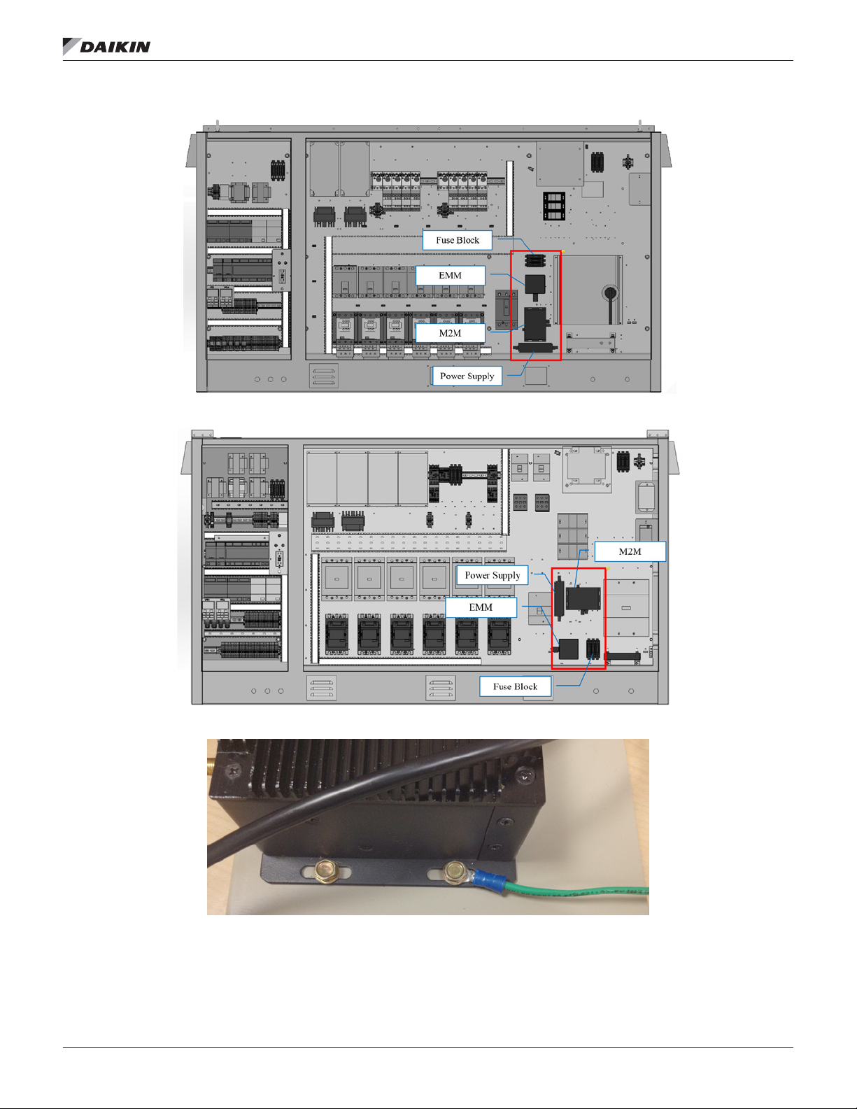
Figure 3: Component locations – AGZ-D Large Panel
Figure 4: Component locations – AGZ-E Large Panel
InsTallaTIon
Figure 5: Installation of Grounding Ring to M2M Gateway
www.DaikinApplied.com 7 IM 1240-1 • INTELLIGENT EQUIPMENT
Page 8

InsTallaTIon
Installing Energy Management Module
Prior to installing any Intelligent Equipment components, power
must be removed from the unit. Power must be removed
at the breaker panel serving the unit, and proper lockout/
tagout procedures should be followed for the duration of the
install. After removing unit power at the breaker panel, the
installer must verify the absence of power at the unit using a
multimeter. Only if power has been veried absent, should the
technician begin the install. The retrot kit is shipped with the
EMM shipped loose. The EMM must be installed inside the unit
control panel.
The installation location will vary depending on the unit model
and size of the control enclosure (see Figure 1 through Figure
4 for correct component locations). Begin by positioning the
EMM on the backplane of the enclosure and marking the screw
holes. Next, drill pilot holes, through the marks just created,
using a 7/64" drill bit. Finally, attach the EMM to the backplane
using (4) of the provided #6 sheet metal screws (5/16" head).
Installing Power Supply
Prior to installing any Intelligent Equipment components, power
must be removed from the unit. Power must be removed at
the breaker panel serving the unit, and proper lockout/tagout
procedures should be followed for the duration of the install.
After removing unit power at the breaker panel, the installer
must verify the absence of power at the unit using a multimeter.
Only if power has been veried absent, should the technician
begin the install.
The retrot kit is shipped with the power supply shipped loose.
The power supply must be installed inside the unit control
panel. The installation location will vary depending on the unit
model and size of the control enclosure (see Figure 1 through
Figure 4 for correct component locations).
Begin by positioning the power supply on the backplane of the
enclosure and marking the screw holes. Next, drill pilot holes,
through the marks just created, using a 7/64" drill bit. Finally,
attach the power supply to the backplane using (2) of the
provided #6 sheet metal screws (5/16" head).
Installing Fuse Block
Prior to installing any Intelligent Equipment components, power
must be removed from the unit. Power must be removed at
the breaker panel serving the unit, and proper lockout/tagout
procedures should be followed for the duration of the install.
After removing unit power at the breaker panel, the installer
must verify the absence of power at the unit using a multimeter.
Only if power has been veried absent, should the technician
begin the install. The retrot kit is shipped with the fuse block
shipped loose. The fuse block must be installed inside the unit
control panel. The installation location will vary depending on
the unit model and size of the control enclosure (see Figure 1
through Figure 4 for correct component locations).
Begin by removing the fuse covers and fuses from the fuse
block (Figure 6). Prior to removal, make note of fuse orientation
within the fuse block. Then, position the fuse block on the
backplane of the enclosure and mark the screw holes. Next,
drill pilot holes, through the marks just created, using a 1/8"
drill bit.
Finally, attach the fuse block to the backplane using (2) of the
provided #8 sheet metal screws (5/16" head). Fuses can be
reinstalled, but the covers should remain off for subsequent
install of necessary wiring.
Figure 6: Fuse Block with Covers and Fuses Removed
IM 1240-1 • INTELLIGENT EQUIPMENT 8 www.DaikinApplied.com
Page 9

Control Cabinet Penetrations
Only the antenna cable(s) must be routed to the outside of
the control enclosure; all other terminations remain within
the control enclosure. This is done using a specic available
knockout. The location of the correct knockout will vary
depending on the unit model and size of the control enclosure
(see Figure 7 through Figure 9 for knockout locations).
First, determine the correct knockout to remove, then remove
it using a hammer, at screwdriver and pliers. Use the hammer
to gently tap the at blade of a screwdriver into the open slit
of the knockout. Once enough separation is gained between
the knockout and the panel, use the pliers to fully remove the
knockout. Insert the provided 0.875" grommet into the control
enclosure from the outside. The knockout is now prepared for
routing of the antenna cable(s).
InsTallaTIon
Figure 8: AGZ Medium Enclosure Knockout Location (Rear
of Enclosure)
Figure 7: AGZ Small Enclosure Knockout Location (Rear
of Enclosure)
Figure 9: AGZ Large Enclosure Knockout Location (Rear
of Enclosure)
www.DaikinApplied.com 9 IM 1240-1 • INTELLIGENT EQUIPMENT
Page 10

Wiring interconnections
InsTallaTIon
DANGER
Electric shock hazard. Can cause personal injury or
equipment damage.
Prior to installing Intelligent Equipment hardware, power must
be removed from the unit. This means removing power at the
breaker panel serving the unit, and following proper lockout/
tagout procedures at said breaker panel for the duration of
the install. Power should not be reapplied until all electrical
interconnections have been made and veried.
This equipment must be properly grounded. Connections
and service to the MicroTech III Air-Cooled Chiller Controller,
Machine-to-Machine Gateway and Energy Management
Module must be performed only by personnel knowledgeable
in the operation of the equipment being controlled.
CAUTION
Static sensitive components. Can cause equipment damage.
Discharge any static electrical charge by touching the bare
metal inside the control panel before performing any service
work. Never unplug cables, circuit board terminal blocks, or
power plugs while power is applied to the panel.
M2M Connection to MTIII
The M2M Gateway is connected to the MicroTech III unit
controller via Ethernet. Connect one end of the provided 6'
Ethernet Patch cable to the M2M port marked, “ETH”, and the
other end to the MicroTech III Unit controller port marked, “TIP”
(Figure 10).
M2M Connection to EMM
The M2M Gateway is connected to the EMM via USB. Connect
the type-A end of the provided 3' USB cable to the M2M port
marked, “USB1”, and the type-B end of the same cable to the
USB port of the EMM (Figure 11).
Figure 11: USB Connections
Figure 10: ‘ETH’ and ‘TIP’ Ports
IM 1240-1 • INTELLIGENT EQUIPMENT 10 www.DaikinApplied.com
Page 11

InsTallaTIon
Connection of Power Supply
The M2M Gateway is powered by a 120VAC (primary) to
24VDC (secondary) power supply. The 24 VDC connection
is made via a pre-fabricated, keyed plug coming from the low
voltage end of the power supply. Connect this plug to the M2M
Gateway receptacle marked, “Power Input” (Figure 12).
The 120VAC cable has the jacket and insulation pre-stripped,
with the ends of both the Line and Neutral wires tinned.
On a MicroTech III AGZ-D or AGZ-E unit, connect the Line
(brown) conductor to terminal TB1-11B and the Neutral (blue)
conductor to terminal TB1-32B (Figure 13).
Figure 12: M2M Power Input
Connection of EMM to CT’s
The high voltage side of the EMM has a hinged cover, which
must be opened. First, remove the two installation screws
(Figure 14), then ip the cover open. The EMM uses an open
style hinge, so it may be easier to completely remove the
hinged door while installing conductors.
The CT’s have built-in output conductors, which must be
connected to the EMM. Each black conductor must be
connected to an EMM terminal labeled, “CT”, while each white
conductor must be connected to the corresponding terminal
labeled, “A”, “B”, or “C”. The two conductors from each CT
must be connected to the same terminal set, i.e. – “CT” and
“A”, “CT” and “B”, or “CT” and “C”. For each CT, the white wire
must go to terminal labeled ‘CT’ and the black wire must go to
the associated lettered terminal (Figure 15).
Figure 14: Hinged Cover Screw Locations
Figure 13: AGZ-D and AGZ-E 120VAC Wiring
Figure 15: Connection of EMM to CT’s
www.DaikinApplied.com 11 IM 1240-1 • INTELLIGENT EQUIPMENT
Page 12

InsTallaTIon
Installing CT’s
Current Transformers (CT’s) are split-core type, to make
installation easier. Snap split-core CT connected to EMM
terminal CT_A on phase L1, snap split-core CT connected
to EMM terminal CT_B on phase L2, and snap split-core CT
connected to EMM terminal CT_C on phase L3 (Figure 16).
Ensure that the “Load” indicator on the CT is oriented correctly.
Figure 16: CT Installation
Connection of EMM to Line Voltage
The EMM is connected to Line Voltage through the Fuse
Block. Begin by removing the fuse covers and fuses from the
Fuse Block. Prior to removal, make note of fuse orientation
within the fuse block. Next, using the provided 6" wiring
harness, connect the “VinA” (Tan), “VinB” (Violet), and “VinC”
(Orange) terminals on the EMM to the “Load” terminals on the
Fuse Block (Figure 17).
Next, remove the plastic protective shield from Power
Distribution Block 1 (PD1).Using the provided 6' wiring
harness, connect the corresponding “Line” terminals on the
Fuse Block to the control panel (PD1) terminals “T1”, “T2”,
and “T3”, such that EMM terminal “VinA” (Tan) is connected
to PD1-T1, “VinB”(Violet) is connected to PD1-T2, and “VinC”
(Orange) is connected to PD1-T3 (Figure 18).
Figure 17: EMM Connection to Fuse Block
Figure 18: Fuse Block Connected to Line Voltage
IM 1240-1 • INTELLIGENT EQUIPMENT 12 www.DaikinApplied.com
Page 13

Connection of M2M and EMM to Ground
One end of the M2M ground conductor should already be
connected to the M2M case (see section entitled, “Installing
M2M Gateway”). Connect the tinned end of the EMM ground
conductor to the “GND” terminal on the EMM itself (Figure 19).
Connect the free ring terminals for both the M2M and EMM to
the nearest available grounding lug in the control enclosure
(Figure 20).
Once all connections are made to the line voltage side of the
EMM, close the hinged cover, and reinstall the screws. Figure
21 depicts an EMM with all high voltage terminations made and
the hinged cover reinstalled.
Figure 19: Ground Wire Connected to EMM
InsTallaTIon
Figure 20: Typical Grounding Lug
Figure 21: EMM Following Reinstallation of Hinged Cover
www.DaikinApplied.com 13 IM 1240-1 • INTELLIGENT EQUIPMENT
Page 14

Antenna Installation
InsTallaTIon
DANGER
Electric shock hazard. Can cause personal injury or
equipment damage.
Prior to installing Intelligent Equipment hardware, power must
be removed from the unit. This means removing power at the
breaker panel serving the unit, and following proper lockout/
tagout procedures at said breaker panel for the duration of
the install. Power should not be reapplied until all electrical
interconnections have been made and veried.
This equipment must be properly grounded. Connections
and service to the MicroTech III Air-Cooled Chiller Controller,
Machine-to-Machine Gateway and Energy Management
Module must be performed only by personnel knowledgeable
in the operation of the equipment being controlled.
CAUTION
Static sensitive components. Can cause equipment damage.
Discharge any static electrical charge by touching the bare
metal inside the control panel before performing any service
work. Never unplug cables, circuit board terminal blocks, or
power plugs while power is applied to the panel.
WARNING
Sharp edges on sheet metal and fasteners can cause
personal injury. This equipment must be installed, operated,
and serviced only by an experienced installation company
and fully trained personnel.
Mounting
The antennas provided with the Daikin Applied Intelligent
Equipment solution (Figure 22) are omni-directional, and utilize
a swiveling base that allows the antenna to be oriented to
avoid interference from structures or other antennas. For initial
installation, it is recommended to install the antenna on top
of the chiller, with enough clearance from the edge to avoid
accidental contact or damage. The antenna is held in place by
its magnetic base. You will nd more information about aiming
antennas in the, “Cellular Conguration”, “Wi-Fi Conguration”,
and “Troubleshooting” sections of this document.
Figure 22: Wireless Antenna on Magnetic Mounting Base
Wiring of Antennas
As described previously, the antenna cable must be fed from
the outside of the unit through the control enclosure and up
to the mounting bracket with the M2M Gateway, EMM, power
supply, and fuse block. The connection is made by screwing
the SMA coaxial connector onto the appropriate M2M SMA
coaxial connector; “3G/GPRS” for cellular or “WLAN” for Wi-Fi.
(Figure 23).
Figure 23: 3G and WLAN Connections
IM 1240-1 • INTELLIGENT EQUIPMENT 14 www.DaikinApplied.com
Page 15

Verify Time Zone Information
The M2M Gateway comes pre-congured from the factory
with the Time and Time Zone set based on the location of the
installation site. However, the installer should conrm that
the factory setting is accurate, and ensure that the correct
information is also set in the MicroTech III Chiller controller.
1. Using a laptop computer and Ethernet cable, connect
to the “ETH” port of the M2M Gateway (you will need to
temporarily disconnect the Ethernet cable between the
M2M Gateway and the MicroTech III controller, to make
use of the “ETH” port on the M2M Gateway).
a. The Cellular strength of the M2M Gateway is
veried using an HTML Interface page in an
HTTP server.
b. In order to access this page, your computer must
be on the same subnet as the M2M Gateway,
which is shipped set to a default IP subnet mask
(255.255.0.0) and IP address (172.31.255.1). You
must change the computer’s network settings to
match the subnet (the signal strength verication
process is the same regardless of the operating
system on your computer).
c. Navigate to your laptop’s Local Area Connection
settings screen and change the IP subnet mask to
255.255.0.0, and the IP address to be compatible
with the default M2M Gateway IP address
listed above (example: 172.31.255.7). For more
information on how to change your computer’s IP
settings, consult the Operating System’s “Help” les.
d. Temporarily disable the wireless adapter(s) on the
computer, as these may prevent accessing the
HTML Interface page.
2. Open a web browser page and type, 172.31.255.1, then
press enter.
a. When prompted, enter the User Name: “root”
b. Enter the Password: “root”
c. This opens the Gateway home page.
3. Click the ‘System’ tab (Figure 24 on page 16).
a. Select the ‘Settings’ tab
b. Under ‘Time Zone’, verify that the indicated Time
Zone is accurate. If so, continue to step 5.
4. If the Time Zone is inaccurate, use the list to select the
correct Time Zone, then click, ‘Save Changes’.
a. After saving changes, the screen will refresh.
InsTallaTIon
5. Click, ‘Apply Changes’ to write the change to the
Gateway’s conguration le.
a. After applying changes, the screen will briey
indicate that the conguration is being updated,
then will refresh to display the new time zone.
6. You will notice that the time in the upper right corner of
the webpage will now reect accurately based on the
selected Time Zone (Figure 25).
7. Once the Time Zone is veried in the M2M Gateway, you
will verify the time in the MicroTech III Chiller controller.
Begin by entering the password of 6363. Next, from the
main menu of the unit controller (Figure 27), turn the
knob clockwise until ‘View/Set Unit’ is highlighted, then
depress the knob to enter the ‘View/Set Unit’ menu.
a. Press in on the knob to enter the ‘View/Set Unit’
menu
8. From the ‘View/Set Unit’ menu, turn the knob
clockwise until ‘Date/Time/Schedules’ is highlighted.
Depress the knob to enter the ‘Date/Time/Schedules’
menu. Verify that the ‘Time’, ‘Date’, and ‘UTC Diff’
(Figure 26) are all correct. If any require a change,
simply use the knob to highlight that eld, then press in
on the knob to select, which makes the item adjustable.
Use the knob to increase/decrease the value, then
press in on the knob to enter
9. Once the ‘Time’, ‘Date’, and ‘UTC Diff’ are all correct,
press the BACK button to return to the main menu.
NOTE: For more information on navigating the MicroTech III
rooftop unit controller keypad display, please see the
appropriate operation manual for the unit model.
www.DaikinApplied.com 15 IM 1240-1 • INTELLIGENT EQUIPMENT
Page 16

Figure 24: System Tab
InsTallaTIon
Figure 25: Time Updated to Time Zone Figure 26: Date/Time/Schedules Menu
Figure 27: Keypad Controls
IM 1240-1 • INTELLIGENT EQUIPMENT 16 www.DaikinApplied.com
Page 17

Cellular Conguration
The following procedures should be used to congure the
Intelligent Equipment solution for Cellular connectivity:
1. Mount and connect the wireless antenna per the
instructions included in document section, Antenna
Installation on page 14.
2. Using a laptop computer and Ethernet cable, connect
to the “ETH” port of the M2M Gateway (you will need to
temporarily disconnect the Ethernet cable between the
M2M Gateway and the MicroTech III controller, to make
use of the “ETH” port on the M2M Gateway).
a. The Cellular strength of the M2M Gateway is
veried using an HTML Interface page in an
HTTP server.
b. In order to access this page, your computer must
be on the same subnet as the M2M Gateway,
which is shipped set to a default IP subnet mask
(255.255.0.0) and IP address (172.31.255.1). You
must change the computer’s network settings to
match the subnet (the signal strength verication
process is the same regardless of the operating
system on your computer).
c. Navigate to your laptop’s Local Area Connection
settings screen and change the IP subnet mask to
255.255.0.0, and the IP address to be compatible
with the default M2M Gateway IP address
listed above (example: 172.31.255.7). For more
information on how to change your computer’s IP
settings, consult the Operating System’s “Help” les.
d. Temporarily disable the wireless adapter(s) on the
computer, as these may prevent accessing the
HTML Interface page.
3. Open a web browser page and type, 172.31.255.1, then
press enter.
a. When prompted, enter the User Name: “root”
b. Enter the Password: “root”
c. This opens the Gateway home page (Figure 28 on
page 18).
InsTallaTIon
4. Click the ‘Status’ tab
a. Select the ‘WWAN Modem’ tab
b. Under “Signal Quality, verify cellular signal strength
(Figure 29).
5. Adjust antenna as necessary to establish a strong
cellular connection
a. For reliable operation, signal quality and power
should both be in the good or excellent range.
b. As the antenna is adjusted, be mindful that
signal strength is impacted by structures or other
antennas. As much as practically possible, make
efforts to avoid such interference while adjusting
the antenna.
6. Once a strong cellular connection is obtained, close the
web browser, and disconnect the Ethernet cable between
the laptop and M2M Gateway.
7. Reconnect the Ethernet cable between the M2M
Gateway and the MicroTech III controller.
8. Feed excess antenna cable into the control enclosure,
then tighten waterproof grommet.
9. Add a bead of silicone around the perimeter of the
waterproof grommet penetration into the control
enclosure.
10. On inside of enclosure, secure excess antenna cable
using zip ties.
www.DaikinApplied.com 17 IM 1240-1 • INTELLIGENT EQUIPMENT
Page 18

Figure 28: M2M Gateway Home Page
InsTallaTIon
Figure 29: Verify Cellular Signal Strength
IM 1240-1 • INTELLIGENT EQUIPMENT 18 www.DaikinApplied.com
Page 19

Wi-Fi Conguration
The following procedures should be used to congure the
Intelligent Equipment solution for Wi-Fi connectivity:
1. Mount and connect the wireless antenna per the
instructions included in document section, Antenna
Installation on page 14.
2. Using a laptop computer and Ethernet cable, connect
to the “ETH” port of the M2M Gateway (you will need to
temporarily disconnect the Ethernet cable between the
M2M Gateway and the MicroTech III controller, to make
use of the “ETH” port on the M2M Gateway).
a. The Wi-Fi settings of the M2M Gateway are
congured using HTML Interface pages in an
HTTP server.
b. In order to access these pages, your computer
must be on the same subnet as the M2M Gateway,
which is shipped set to a default IP subnet mask
(255.255.0.0) and IP address (172.31.255.1). You
must change the computer’s network settings to
match the subnet (the Wi-Fi conguration process
is the same regardless of the operating system on
your computer).
c. Navigate to your laptop’s Local Area Connection
settings screen and change the IP subnet mask to
255.255.0.0, and the IP address to be compatible
with the default M2M Gateway IP address
listed above (example: 172.31.255.7). For more
information on how to change your computer’s IP
settings, consult the Operating System’s “Help”
les.
d. Temporarily disable the wireless adapter(s) on the
computer, as these may prevent accessing the
HTML Interface pages.
3. Open a web browser page and type, 172.31.255.1, then
press enter.
a. When prompted, enter the User Name: “root”
b. Enter the Password: “root”
c. This opens the Gateway home page (Figure 30 on
page 20).
4. If the M2M Gateway will be using DHCP, skip to step 6.
If the M2M Gateway will be using a Static IP address, go
to step 5.
InsTallaTIon
5. Click the ‘Network’ tab
a. Under wlan0 Conguration (Figure 31), select
‘Static IP’ for Connection Type
b. Enter the IP, Subnet, and Gateway address
information
c. Under wlan0 DNS Servers enter the primary DNS
server and click ‘Add’
d. If a secondary DNS server address is to be
entered, enter it after the page has reloaded and
click ‘Add’ and enter the secondary address.
e. Click ‘Save’.
6. Click the ‘Wireless’ tab ( Figure 32)
a. Enter the ESSID of the network
b. If Wi-Fi security is enabled enter in Wi-Fi network
SSID and password and security type
7. Click the ‘Save Changes’ button in the lower right corner
of the page.
8. Click the System tab, then click the Reboot tab.
a. Click the ‘Yes, really reboot now’ button
b. The gateway will automatically refresh after several
minutes.
9. Click the ‘Status’ tab
a. Under ‘WLAN’, verify Wi-Fi signal strength (Figure
33).
10. Adjust antenna as necessary to establish a strong Wi-Fi
connection
a. For reliable operation, signal level should be 60
dBm or lower and link quality power should be
50/70 or higher.
b. As the antenna is adjusted, be mindful that
signal strength is impacted by structures or other
antennas. As much as practically possible, make
efforts to avoid such interference while adjusting
the antenna.
11. Once a strong Wi-Fi connection is obtained, close the
web browser, and disconnect the laptop and Ethernet
cable from the M2M Gateway.
12. Reconnect the Ethernet cable between the M2M
Gateway and the MicroTech III controller.
13. Feed excess antenna cable into the control enclosure,
then tighten waterproof grommet.
14. Add a bead of silicone around the perimeter of the
waterproof grommet penetration into the control
enclosure.
15. On inside of enclosure, secure excess antenna cable
using zip ties.
www.DaikinApplied.com 19 IM 1240-1 • INTELLIGENT EQUIPMENT
Page 20

Figure 30: M2M Gateway Home Page
InsTallaTIon
Figure 31: Wireless LAN Conguration
IM 1240-1 • INTELLIGENT EQUIPMENT 20 www.DaikinApplied.com
Page 21

Figure 32: Wireless Conguration Screen
InsTallaTIon
Figure 33: Wireless Signal Strength
www.DaikinApplied.com 21 IM 1240-1 • INTELLIGENT EQUIPMENT
Page 22

Conguration for Hard-Wired Connection
The M2M Gateway is congured using a set of HTML interface
pages within the Wind River Intelligent Device Platform.
The table below indenties the Wind River conguration
parameters, along with the corresponding physical port
on the M2M Gateway. For reference, it also includes the
corresponding device connection to the M2M Gateway.
Wind River
conguration
parameter
LAN ETH (which is eth0) MTIII Unit Controller
wan USB2 (which is eth1) Local Network
wlan0 WLAN WiFi
wwan 3G/GPRS Cellular
M2M Gateway port Device Connection
The following procedures should be used to congure the
Intelligent Equipment solution for hard-wired Local Area
Network (LAN) connectivity (note: it is the “wan” interface in the
gateway that will be congured):
1. Remove the USB-to-Ethernet converter from the
envelope and connect it to an open USB port on the
M2M Gateway (this is necessary because the M2M
Gateway has a single Ethernet plug, which is connected
to the MicroTech III controller, and, therefore, unavailable
for the purpose of connecting to the local network).
a. Connect the provided Ethernet patch cable to the
USB-to-Ethernet adapter and to the local network
(DHCP is enabled by default).
2. Using a laptop computer and Ethernet cable, connect
to the “ETH” port of the M2M Gateway (you will need to
temporarily disconnect the Ethernet cable between the
M2M Gateway and the MicroTech III controller, to make
use of the “ETH” port on the M2M Gateway).
a. The hard-wired Local Area Network (LAN) settings
of the M2M Gateway are congured using HTML
interface pages in an HTTP server.
b. In order to access these pages, your computer
must be on the same subnet as the M2M Gateway,
which is shipped set to a default IP subnet mask
(255.255.0.0) and IP address (https://172.31.255.1).
You must change the computer’s network settings to
match the subnet.
c. Navigate to your laptop’s Local Area Connection
settings screen and change the IP subnet mask to
255.255.0.0, and the IP address to be compatible
with the default M2M Gateway IP address
listed above (example: 172.31.255.7). For more
information on how to change your computer’s
IP settings, consult your PC operating system’s
“Help” les.
d. Temporarily disable the wireless adapter(s) on the
computer, as these may prevent accessing the
HTML Interface pages.
3. Open a web browser and type, https://172.31.255.1, then
NOTE: If you will use DHCP for your local network
4. Click the ‘Network’ tab
5. Locate the ‘wan Conguration’ section (Figure 35 on
6. Click the ‘Save Changes’ button in the lower right corner
7. Click the ‘Apply Changes’ button in the lower right-hand
8. Click the ‘Multiwan’ tab
9. Once created, set “ICMP hosts” of new interface to
10. Under ‘Priority Interface’, set to “wan”
InsTallaTIon
press enter.
a. When prompted, enter the User Name: “service”.
b. Enter the unique password that was provided with
the Gateway hardware and press ENTER.
c. This opens the Wind River Intelligent Device
Platform conguration page in the gateway (Figure
34 on page 23).
conguration, please proceed to step 8.
page 24)
a. Under wan Conguration select ‘Static IP’ for
Connection Type
b. Ensure that Interface = eth1
c. Enter the IP, Subnet, and Gateway address
information
d. Under wan DNS Servers enter your network’s
primary DNS server and click ‘Add’ (NOTE: If you
prefer to use a public DNS server, use 8.8.8.8 or
4.2.2.2)
e. If a secondary DNS server address is to be
entered, enter it after the page has reloaded and
click ‘Add’ and enter the secondary address.
of the page.
a. IMPORTANT: Allow the page to refresh
b. Conrm that there is number in parentheses next
to “Review Changes”. If so, proceed to step 7; if
not, repeat steps 5 and 6.
corner of the screen. The page will automatically refresh
when complete (this can take as much as two minutes).
a. Scroll to the bottom of the page and Click ‘Add
New Interface’ (Figure 36 on page 24)
b. Name the interface, “wan” (must match the name
of the interface congured in step 5.
c. Click ‘Add new interface’
“disable”
IM 1240-1 • INTELLIGENT EQUIPMENT 22 www.DaikinApplied.com
Page 23

InsTallaTIon
11. Click ‘Save changes’ button
a. IMPORTANT: Allow the page to refresh
b. Conrm that there is number in parentheses next
to “Review Changes”. If so, proceed to step 12; if
not, repeat steps 8-11.
12. Remove ‘wwan’ interface
13. Remove ‘wlan0’ interface
14. Click the ‘Save Changes’ button
a. IMPORTANT: Allow the page to refresh
b. Conrm that there is number in parentheses next
to “Review Changes”. If so, proceed to step 15; if
not, repeat steps 8-14.
15. Click the ‘Apply Changes’ button in the lower right-hand
corner of the screen. The page will automatically refresh
when complete (this can take as much as two minutes).
Figure 34: M2M Gateway Home Page
16. Conrm that ‘ICMP host’ of “wan” interface is still set to
“disable”
a. If so, go to step 17.
b. If not, set to “disable”
c. Click ‘Save changes’ button
i. IMPORTANT: Allow the page to refresh
ii. Conrm that there is number in parentheses
next to “Review Changes”. If so, proceed to step
17; if not, repeat steps 8-16.
d. Click the ‘Apply Changes’ button in the lower
right-hand corner of the screen. The page will
automatically refresh when complete (this can take
as much as two minutes).
17. Click the ‘System’ tab, then click the Reboot button.
18. Reconnect the Ethernet cable between the M2M
Gateway and the MicroTech III controller. Procedure
complete.
NOTE: Be certain that the IT staff has allowed incoming and
outgoing internet trafc on TCP ports 80, 443, 3197,
3199, 5222, 5223 and 8080.
www.DaikinApplied.com 23 IM 1240-1 • INTELLIGENT EQUIPMENT
Page 24

Figure 35: WAN Conguration Settings
Figure 36: ‘Add New Interface’ Selection
InsTallaTIon
IM 1240-1 • INTELLIGENT EQUIPMENT 24 www.DaikinApplied.com
Page 25

Potential issues:
Gateway does not power up (LED does not illuminate)
• Verify 120V at TB1
• Verify that power supply wires are properly installed in
terminals 1 and 3
• Verify that power supply is properly connected to the
Gateway
• Contact Daikin Applied
Energy Management Module does not power up
• Verify USB cable connection to Gateway and Energy
Management Module
• Verify that Gateway has power
• Contact Daikin Applied
Cell connection cannot be established
• Check antenna connection to magnetic base
• Check antenna connection to 3G/GPRS connection on
Gateway
• Check signal strength through WebIF
• Verify APN settings
• Verify that neither a LAN or Wi-Fi connection has been
established
• Conrm SIM card installation and recognition by gateway
• Contact Daikin Applied
TroubleshooTIng
TroubleshooTIng
Wi-Fi connection cannot be established
• Check antenna connection to magnetic base
• Check antenna connection to WLAN connection on
Gateway
• Check signal strength through WebIF
• Verify Wi-Fi IP addressing, ESSID, and login credentials
match customer supplied Wireless LAN requirements
• Connect to Wi-Fi network and try to ping the Gateway’s
WLAN IP address
• Verify that neither a LAN or Cell connection has been
established
• Contact Daikin Applied
LAN connection cannot be established
• Conrm proper installation of USB to Ethernet adapter
• Verify LED activity on USB to Ethernet adapter
• Verify LAN addressing through Web IP
• Connect to LAN and try to ping the Gateway’s LAN IP
address
• Verify that neither a Wi-Fi or Cell connection has been
established
• Contact Daikin Applied
MicroTech III Data Not Showing Up In User Interface
• Conrm Ethernet cable is plugged into ‘ETH’ port on
Gateway
• Conrm Ethernet cable is plugged into ‘TIP’ port on
MicroTech III controller
• Check for LED activity on Gateway’s ETH port
• Verify IP address of Eth0 on the Gateway is 192.168.1.40
• Verify IP address of the MicroTech III controller is
192.168.1.42
— View/Set Unit —> Ctrlr IP Setup
• Contact Daikin Applied
www.DaikinApplied.com 25 IM 1240-1 • INTELLIGENT EQUIPMENT
Page 26

Appendix A
Wi-Fi or Hardwired LAN Ethernet connection Pre-Start-up Form
appendIx
appendIx
The Intelligent Equipment gateway is capable of
communicating via cellular connection, Wi-Fi Ethernet
connection, or hardwired LAN Ethernet connection. For either
Ethernet connection the gateway supports DHCP to have an IP
address assigned automatically, or it can be eld programmed
with a static IP address.
If an Ethernet connection is to be used for either type, the
customer’s LAN Administrator should review and supply the
following information (as necessary) prior to going to the
jobsite and commissioning the gateway.
1. IT Group must allow incoming and outgoing internet trafc on TCP ports 80, 443, 3197, 3199, 5222, 5223 and 8080 for
hardwired LAN connections.
2. If the gateway will be required to use a static IP address the following information will need to be supplied:
Internal LAN Static IP Address: — — — (required)
IP Subnet Mask: — — — (required)
Default Gateway: — — — (required)
DNS Server (primary): — — — (required)
DNS Server (secondary): — — — (if applicable)
Proxy Server IP Address: — — — (if applicable)
Proxy Server Port Number: (if applicable)
A CAT 5E Ethernet communication cable with an extra:
feet of coiled cable and a RJ45 connector on the
free end has been run per local codes from the customer’s
LAN to the unit main control box of each unit with an Intelligent
Equipment gateway.
3. For Wi-Fi Ethernet connections the following information will be required as well:
Wi-Fi network SSID:
Wi-Fi network password:
Wi-Fi encryption type:
Wi-Fi Mode:
Preferred Wi-Fi channel:
IM 1240-1 • INTELLIGENT EQUIPMENT 26 www.DaikinApplied.com
Page 27

Page 28

Daikin Applied Training and Development
Now that you have made an investment in modern, efcient Daikin equipment, its care should be a high
priority. For training information on all Daikin HVAC products, please visit us at www.DaikinApplied.com
and click on Training, or call 540-248-9646 and ask for the Training Department.
Warranty
All Daikin equipment is sold pursuant to its standard terms and conditions of sale, including Limited
Product Warranty. Consult your local Daikin Applied representative for warranty details. To nd your
local Daikin Applied representative, go to www.DaikinApplied.com.
Aftermarket Services
To nd your local parts ofce, visit www.DaikinApplied.com or call 800-37PARTS (800-377-2787).
To nd your local service ofce, visit www.DaikinApplied.com or call 800-432-1342.
This document contains the most current product information as of this printing. For the most up-to-date
product information, please go to www.DaikinApplied.com.
Products manufactured in an ISO Certied Facility.
IM 1240-1 (11/15) ©2015 Daikin Applied | (800) 432–1342 | www.DaikinApplied.com
 Loading...