

Goodman A/GPG13 M SERIES W/R410A, GPG1324***M, GPG1330***M, GPG1336***M, GPG1342***M Installation & Operating Instructions Manual
...Page 1
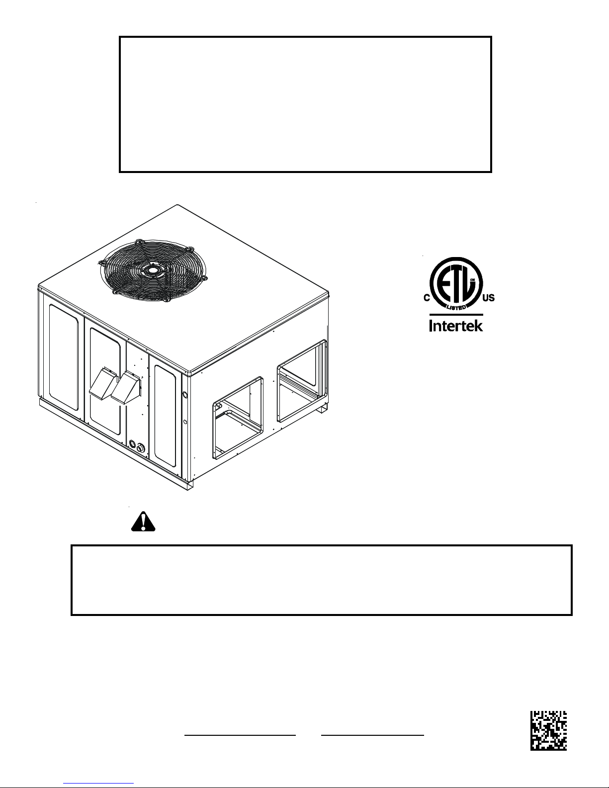
INSTALLATION & OPERATING
INSTRUCTIONS for
A/GPG13 M SERIES W/R410A
SINGLE PACKAGE GAS-ELECTRIC
HEATING & COOLING UNIT
Affix this manual and Users Information Manual adjacent to the unit.
This Forced Air Central Unit Design Complies With
Requirements Embodied in The American National
Standard / National Standard of Canada Shown Below.
ANSI Z21.47•CSA-2.3 Central Furnaces
RECOGNIZE THIS SYMBOL AS A SAFETY PRECAUTION.
ATTENTION INSTALLING PERSONNEL
Prior to installation, thoroughly familiarize yourself with this Installation Manual. Observe all safety warnings. During
installation or repair, caution is to be observed.
It is your responsibility to install the product safely and to educate the customer on its safe use.
These installation instructions cover the outdoor
installation of single package gas electric heating and
cooling units. See the Specification Sheet or Technical
Manual applicable to your model* for information
regarding accessories.
*NOTE: Please contact your distributor or
our website for the applicable
Specification Sheet or Technical Manual
referred to in this manual.
IO-357D 5151 San Felipe, Suite 500, Houston, TX 77056
11/12 www.goodmanmfg.com - or - www.amana-hac.com
© 2009 - 2010, 2012 Goodman Manufacturing Company, L.P.
Goodman Manufacturing Company, L.P.
Page 2

Index
Replacement Parts ................................................................................................................................................................................... 3
RDERING PARTS ..................................................................................................................................................................................... 3
O
Safety Instructions .................................................................................................................................................................................... 3
MPORTANT NOTE TO THE OWNER REGARDING PRODUCT WARRANTY ................................................................................................................... 3
I
Unit location ............................................................................................................................................................................................... 4
A
LL INS TALLATIONS: .................................................................................................................................................................................. 4
GROUND LEVEL I NSTALLATIONS O NLY: ............................................................................................................................................................ 4
OOFTOP INS TALLATIONS ONLY: .................................................................................................................................................................... 5
R
R
OOF CURB INSTALLATIONS ONLY: ................................................................................................................................................................ 5
General Information .................................................................................................................................................................................. 5
RANSPORTATION D AMAGE .......................................................................................................................................................................... 6
T
Rigging Details ........................................................................................................................................................................................... 6
Gas Piping .................................................................................................................................................................................................. 6
HIGH A LTITUDE D ERATE (U.S. INSTALLATIONS ONLY) ....................................................................................................................................... 6
PIPING ................................................................................................................................................................................................... 6
AS PIPING CHECKS ................................................................................................................................................................................. 7
G
Propane Gas Installations ......................................................................................................................................................................... 8
TANKS AND PIPING .................................................................................................................................................................................... 8
Electrical Wiring ........................................................................................................................................................................................ 8
T
HERMOSTAT LOCATION .............................................................................................................................................................................. 8
NIT VOLTAGE ......................................................................................................................................................................................... 9
U
HEAT A NTICIPATOR SETTING ........................................................................................................................................................................ 9
Circulating Air and Filters ....................................................................................................................................................................... 10
AIRFLOW CONVERSION ............................................................................................................................................................................ 10
DUCTWORK .......................................................................................................................................................................................... 10
FILTERS ................................................................................................................................................................................................ 10
Venting ..................................................................................................................................................................................................... 11
FLUE HOOD I NSTALLATION ......................................................................................................................................................................... 11
Condensate Drain .................................................................................................................................................................................... 11
ONDENSATE DRAIN C ONNECTION .............................................................................................................................................................. 11
C
Normal Sequences of Operation ............................................................................................................................................................ 11
HEATING ............................................................................................................................................................................................... 11
COOLING .............................................................................................................................................................................................. 11
FAN ONLY ............................................................................................................................................................................................. 11
Startup, Adjustments, and Checks ........................................................................................................................................................ 11
HEATING S TARTUP ................................................................................................................................................................................... 11
GAS SUPPLY PRESSURE MEASUREMENT ....................................................................................................................................................... 12
AS MANIFOLD P RESSURE MEASUREMENT AND ADJUSTMENT ........................................................................................................................... 13
G
COOLING STARTUP .................................................................................................................................................................................. 15
Troubleshooting ....................................................................................................................................................................................... 15
IGNITION CONTROL E RROR CODES .............................................................................................................................................................. 15
BNORMAL OPERATION - HEATING .......................................................................................................................................................... 15
A
ABNORMAL OPERATION - COOLING .......................................................................................................................................................... 16
Maintenance ............................................................................................................................................................................................ 16
F
ILTER REPLACEMENT OR C LEANING ............................................................................................................................................................ 16
CABINET FINISH MAINTENANCE ................................................................................................................................................................... 17
CLEAN OUTSIDE COIL (QUALIFIED S ERVICER ONLY) ...................................................................................................................................... 17
ONDENSER, EVAPORATOR, AND INDUCED DRAFT M OTORS .............................................................................................................................. 17
C
FLAME SENSOR (QUALIFIED S ERVICER ONLY) ............................................................................................................................................... 17
FLUE PASSAGES (QUALIFIED S ERVICER ONLY ) ............................................................................................................................................... 17
CLEANING FLUE P ASSAGES (QUALIFIED SERVICER ONLY) ................................................................................................................................. 17
MAIN BURNER F LAME (QUALIFIED SERVICER ONLY) ....................................................................................................................................... 17
CLEANING BURNERS ................................................................................................................................................................................ 17
Accessories and Functional Parts ......................................................................................................................................................... 18
HEET METAL A CCESSORIES ..................................................................................................................................................................... 18
S
FUNCTIONAL PARTS ................................................................................................................................................................................ 18
GENERAL INFORMATION ............................................................................................................................................................................ 18
APPENDIX ................................................................................................................................................................................................. 26
Unit Dimensions ...................................................................................................................................................................................... 26
Wiring Diagrams ...................................................................................................................................................................................... 27
Minimum Clearances .............................................................................................................................................................................. 39
Recommended Filter Sizes ..................................................................................................................................................................... 39
2
Page 3
REPLACEMENT PARTS
Keep this literature in a safe place for future reference.
ORDERING P ARTS
When reporting shortages or damages, or ordering repair
parts, give the complete unit model and serial numbers as
stamped on the unit’s nameplate.
Replacement parts for this appliance are available through
your contractor or local distributor. For the location of your
nearest distributor, consult the white business pages, the
yellow page section of the local telephone book or contact:
CONSUMER AFFAIRS
GOODMAN MANUFACTURING COMPANY, L.P.
7401 SECURITY WAY
HOUSTON, TEXAS 77040
(713) 254-4729
SAFETY INSTRUCTIONS
TO THE INSTALLER
Before installing this unit, please read this manual to
familiarize yourself on the specific items which must be
adhered to, including maximum external static pressure to
unit, air temperature rise, minimum or maximum CFM and
motor speed connections.
IMPORTANT N OTE TO THE O WNER REGARDING P RODUCT W ARRANTY
Your warranty certificate is supplied as a separate document with
the unit installed by your contractor. Read the limited warranty certificate carefully to determine what is and is not covered and keep
the warranty certificate in a safe place. If you are unable to locate
the warranty certificate please contact your installing contractor or
contact customer service (877-254-4729) to obtain a copy.
IMPORTANT NOTICE TO GOODMAN
the 10 Year Parts Limited Warranty, online registration must be
completed within 60 days of installation. Online registration is not
required in California or Quebec. Complete warranty details available from your local dealer or, for Goodman® brand products, visit
www.goodmanmfg.com, and for Amana® brand products, visit
www.amana-hac.com.
IMPORTANT NOTICE TO AMANA
Lifetime Heat Exchanger Limited Warranty and the 10 Years Parts
Limited Warranty, online registration must be completed within 60
days of installation. Online registration is not required in California
or Quebec. Full warranty details available at www.amana-hac.com.
To register your Goodman
®
brand unit, go to www.goodmanmfg.com
and click on “Warranty Registration”. Complete the registration as
prompted.
To register your Amana
®
brand unit, go to www.amana-hac.com
and click on “Warranty Registration”. Complete the registration as
prompted.
Product limited warranty certificates for models currently in
production can be viewed at
www.amana-hac.com. If your model is not currently in production
or does not appear on the website, please contact your installing
contractor or contact customer service (at 877-254-4729) to obtain
a copy of your warranty certificate.
Each product overview page contains a Product Warranty link; by
clicking on it you will be able to view the limited warranty coverage
for that specified product. To view warranty registration information,
click on the Product Warranty text on the left navigation panel on
the home page of each website. The Online Product Registration
pages are located in this same section.
®
BRAND OWNERS: To receive
®
BRAND OWNERS: To receive the
www.goodmanmfg.com or
WARNING
DO NOT CONNECT TO OR USE ANY DEVICE THAT IS NOT DESIG N CERTIFIED
BY GOODMAN FOR USE WITH THIS UNIT. SERIOUS PROPERTY DAMAGE,
PERSONAL INJURY, REDUCED UNIT PERFORMANCE AND/
CONDITIONS MAY RESULT FROM THE USE OF SUCH NON-APPROVED DEVICES.
WARNING
SHOULD OVERHEATING OCCUR OR THE GAS SUPPLY FAIL TO SHUT OFF, TURN
OFF THE MANUAL GAS SHUTOFF VALVE EXTERNAL TO THE FURNACE BEFORE
TURNING OFF THE ELECTRICAL SUPPLY.
WARNING
HIS PRODUCT CONTAINS OR PRODUCES A CHEMICAL OR CHEMICALS WHICH
T
MAY CAUSE SERIOUS ILLNESS OR DEATH AND WHICH ARE KNOWN TO THE
S
TATE OF CALIFORNIA TO CAUSE CANCER, BIRTH DEFECTS OR OTHER
REPRODUCTIVE HARM.
WARNING
O AVOID PROPERTY DAMAGE, PERSONAL INJURY OR DEATH, DO NOT USE
T
THIS UNIT IF ANY PART HAS BEEN UNDER WATER.
QUALIFIED SERVICE TECHNICIAN TO INSPECT THE FURNACE AND TO REPLACE
ANY PART OF THE CONTROL SYSTEM AND ANY GAS CONTROL HAVING BEEN
UNDER WATER.
OR HAZARDOUS
I
MMEDIATELY CALL A
3
Page 4
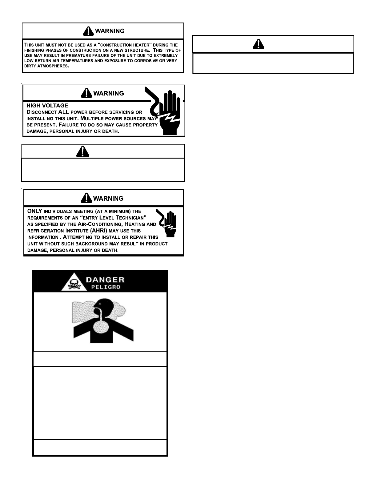
WARNING
CARBON MONOXIDE POISONING HAZARD
TO PREVENT THE RISK OF PROPERTY DAMAGE, PERSONAL INJURY, OR DEATH,
DO NOT STORE COMBUSTIBLE MATERIALS OR USE GASOLINE OR OTHER
FLAMMABLE LIQUIDS OR VAPORS IN THE V ICINITY OF THIS APPLIANCE.
Special Warning for Installation of Furnaces or Air Handling Units in
Enclosed Areas such as Garages, Utility Rooms or Parking Areas
Carbon monoxide producing devices (such as an automobile, space
heater, gas water heater, etc.) should not be operated in enclosed areas
such as unventilated garages, utility rooms or parking areas because of
the danger of carbon monoxide (CO) poisoning resulting from the exhaust
emissions. If a furnace or air handler is installed in an enclosed area such
as a garage, utility room or parking area and a carbon monoxide producing
device is operated therein, there must be adequate, direct outside
ventilation.
UNIT LOCATION
WARNING
O PREVENT POSSIBLE EQUIPMENT DAMAGE, PROPERTY DAMAGE, PERSONAL
T
INJURY OR DEATH, THE FOLLOWING BULLET POINTS MUST BE OBSERVED
WHEN INSTALLING THE UNIT.
ALL I NSTALLATIONS:
• For proper flame pattern within the heat exchanger and
proper condensate drainage, the unit must be mounted
level.
• The flue outlet hood must be at least 12 inches from any
opening through which flue gases could enter a building,
and at least three feet above any forced air inlet located
within ten feet. The economizer/manual fresh air intake/
motorized fresh air intake and combustion air inlet
mounted on the unit are not affected by this restriction.
• To avoid possible corrosion of the heat exchanger, do not
locate the unit in an area where the outdoor air (i.e.
combustion air for the unit) will be frequently contaminated
by compounds containing chlorine or fluorine. Common
sources of such compounds include swimming pool
chemicals and chlorine bleaches, paint stripper,
adhesives, paints, varnishes, sealers, waxes (which are
not yet dried) and solvents used during construction and
remodeling. Various commercial and industrial processes
may also be sources of chlorine/fluorine compounds.
• To avoid possible illness or death of the building occupants,
do NOT locate outside air intake device (economizer,
manual fresh air intake, motorized fresh air intake) too close
to an exhaust outlet, gas vent termination, or plumbing vent
outlet. For specific distances required, consult local codes.
• Allow minimum clearances from the enclosure for fire
protection, proper operation, and service access (see
appendix). These clearances must be permanently
maintained.
• The combustion air inlet and flue outlet hoods on the unit
must never be obstructed. If used, do not allow the
economizer/manual fresh air damper/ motorized fresh air
damper to become blocked by snow or debris. In some
climates or locations, it may be necessary to elevate the
unit to avoid these problems.
• When the unit is heating, the temperature of the return air
entering the unit must be between 50° F and 100° F.
GROUND L EVEL I NSTALLATIONS O NLY:
• When the unit is installed on the ground adjacent to the
building, a level concrete (or equal) base is recommended.
Prepare a base that is 3” larger than the package unit
footprint and a minimum of 3” thick.
• The base should also be located where no runoff of water
from higher ground can collect in the unit.
This ventilation is necessary to avoid the danger of CO poisoning which
can occur if a carbon monoxide producing device continues to operate in
the enclosed area. Carbon monoxide emissions can be (re)circulated
throughout the structure if the furnace or air handler is operating in any
mode.
CO can cause serious illness including permanent brain damage or death.
B10259-216
4
Page 5
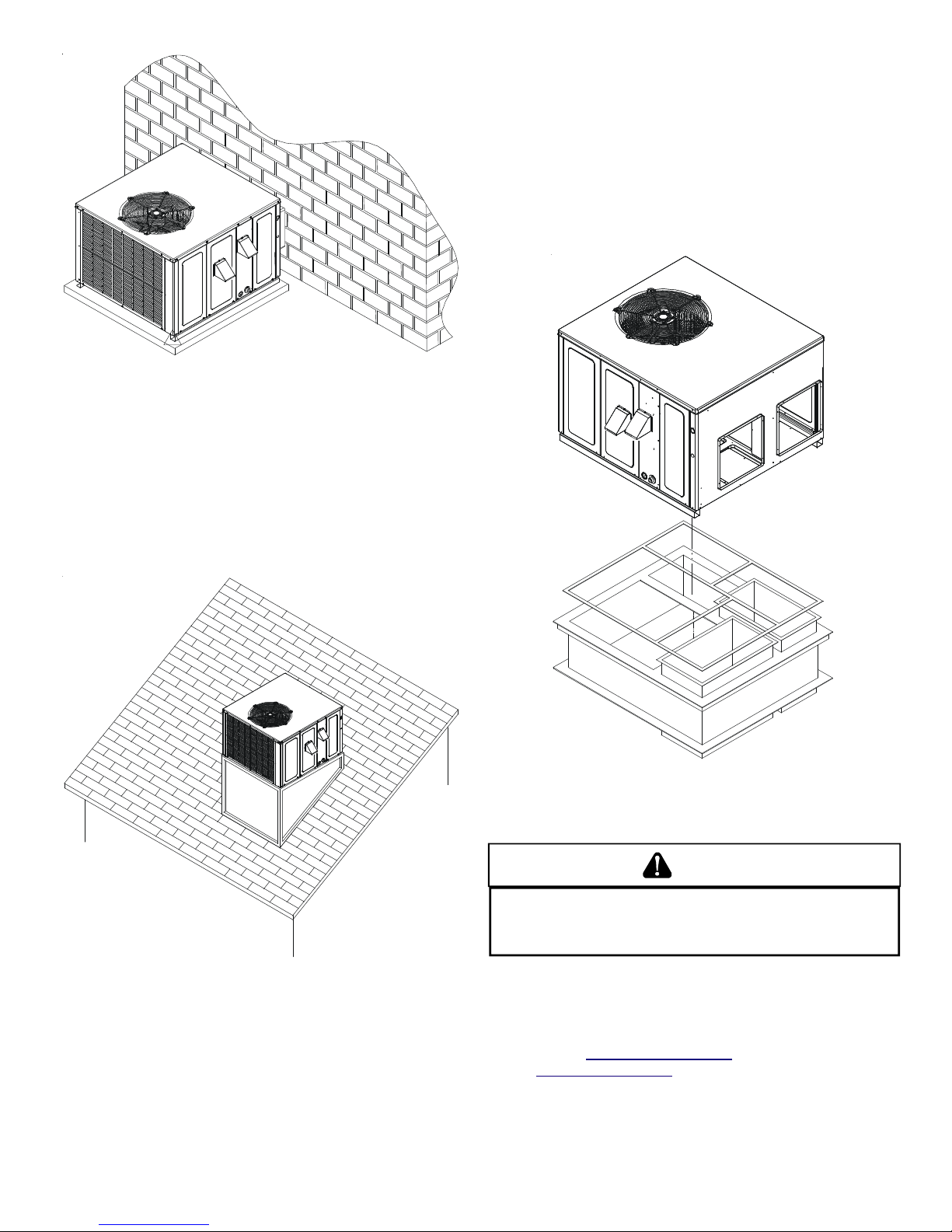
Outside Slab Installation
ROOFTOP I NSTALLATIONS O NLY:
NOTE: To ensure proper condensate drainage, unit must be
installed in a level position.
• To avoid possible property damage or personal injury, the
roof must have sufficient structural strength to carry the
weight of the unit(s) and snow or water loads as required
by local codes. Consult a structural engineer to determine
the weight capabilities of the roof.
ROOF C URB I NSTALLATIONS O NLY:
• Sufficient structural support must be determined prior to
locating and mounting the curb and package unit.
• Ductwork must be constructed using industry guidelines.
The duct work must be placed into the roof curb before
mounting the package unit.
• Curb insulation, cant strips, flashing and general roofing
material are furnished by the contractor.
Rooftop Installation
• The unit may be installed directly on wood floors or on
Class A, Class B, or Class C roof covering material.
• To avoid possible personal injury, a safe, flat surface for
service personnel should be provided.
Roof Curb Installation
GENERAL INFORMATION
WARNING
O PREVENT PROPERTY DAMAGE, PERSONAL INJURY OR DEATH, DUE TO FIRE,
T
EXPLOSIONS, SMOKE, SOOT, CONDENSATION, ELE CTRIC SHOCK OR CARBON
MONOXIDE, THIS UNIT MUST BE PROPERLY INSTALLED, REPAIRED, OPERATED,
AND MAINTAINED.
This unit is approved for outdoor installation ONLY. Rated performance is achieved after 72 hours of operation. Rated performance
is delivered at the specified airflow. See outdoor unit specification sheet for split system models or product specification sheet
for packaged and light commercial models. Specification sheets
can be found at www.goodmanmfg.com for Goodman® brand products or www.amana-hac.com for Amana® brand products. Within
either website, please select the residential or commercial products menu and then select the submenu for the type of product to
be installed, such as air conditioners or heat pumps, to access a
list of product pages that each contain links to that model’s specification sheet.
5
Page 6
To assure that your unit operates safely and efficiently, it must be
installed, operated, and maintained in accordance with these installation and operating instructions, all local building codes and
ordinances, or in their absence, with the latest edition of the National Fuel Gas Code NFPA54/ANSI Z223.1 and National Standard of Canada CAN/CSA B149 Installation Codes.
The heating and cooling capacities of the unit should be greater
than or equal to the design heating and cooling loads of the area to
be conditioned. The loads should be calculated by an approved
method or in accordance with A.S.H.R.A.E. Guide or Manual J Load Calculations published by the Air Conditioning Contractors
of America.
Obtain from:
American National Standards Institute
1430 Broadway
New York, NY 10018
TRANSPORTATION D AMAGE
Check the carton upon arrival for external damage. If damage is
found, a request for inspection by carrier agent should be made in
writing immediately.
Carefully inspect the unit for damage including damage to the
cabinetry. Any bolts or screws which may have loosened in transit
must be retightened. In the event of damage, the receiver should:
1. Make notation on delivery receipt of any visible damage to
shipment or container.
2. Notify carrier promptly and request an inspection.
3. In case of concealed damage, carrier should be notified
as soon as possible-preferably within 5 days.
4. File the claim with the following supporting documents:
a. Original Bill of Lading, certified copy, or indemnity bond.
b. Original paid freight bill or indemnity in lieu thereof.
c. Original invoice or certified copy thereof, showing trade
and other discounts or reductions.
d. Copy of the inspection report issued by carrier
representative at the time damage is reported to the
carrier. The carrier is responsible for making prompt
inspection of damage and for a thorough investigation of
each claim. The distributor or manufacturer will not accept
claims from dealers for transportation damage.
NOTE: When inspecting the unit for transportation damage, remove
all packaging materials. Recycle or dispose of the packaging material according to local codes.
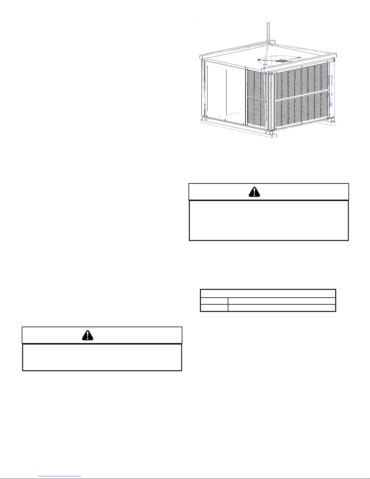
RIGGING DETAILS
WARNING
O PREVENT PROPERTY DAMAGE, THE UNIT SHOULD REMAIN IN AN UPRIGHT
T
T
POSITION DURING ALL RIGGING AND MOVING OPERATIONS.
LIFTING AND MOVING WHEN A CRANE IS USED, PLACE THE UNIT IN AN
ADEQUATE CABLE SLING.
Important: If using bottom discharge with roof curb, ductwork
should be attached to the curb prior to installing the unit. Ductwork
dimensions are shown in roof curb installation instructions.
Refer to the Roof Curb Installation Instructions for proper curb installation. Curbing must be installed in compliance with the National
Roofing Contractors Association Manual.
Lower unit carefully onto roof mounting curb. While rigging unit,
center of gravity will cause condenser end to be lower than supply
air end.
O FACILITATE
Rigging
GAS PIPING
IMPORTANT NOTE: This unit is factory set to operate on natural
gas at the altitudes shown on the rating plate.
WARNING
O AVOID PROPERTY DAMAGE, PERSONAL INJURY OR DEATH WHEN EITHER
T
USING PROPANE GAS ALONE OR AT HIGHER ALTITUDES, OBTAIN AND INSTALL
THE PROPER CONVERSION KIT(S).
UNSATISFACTORY OPERATION AND/OR EQUIPMENT DAMAGE.
U.S
KITS ARE FOR
ANADA.
IN
C
. INSTALLATIONS ONLY AND ARE NOT APPROVED FOR USE
The rating plate is stamped with the model number, type of gas and
gas input rating. Make sure the unit is equipped to operate on the
type of gas available. Conversion to LP gas is permitted with the
use of the factory authorized conversion kit LPT-03. (LPT-00A may
be used on models with AA revisions. LPT-03 is compatible with
both the White Rodgers and the Honeywell gas valves.)
AILURE TO DO S O CAN RESULT IN
F
IGH ALTITUDE
H
Inlet Gas Pressure
Natural Min. 5.0" W.C., Max. 10.0" W.C.
Propane Min. 11.0" W.C., Max. 13.0" W.C.
Inlet Gas Pressure Must Not Exceed the Maximum Value Shown in Table
Above.
The minimum supply pressure should not vary from that shown in
the table above because this could prevent the unit from having
dependable ignition. In addition, gas input to the burners must not
exceed the rated input shown on the rating plate. Overfiring of the
unit could result in premature heat exchanger failure.
HIGH ALTITUDE DERATE (U.S. INSTALLATIONS ONLY)
IMPORTANT NOTE: The gas/electric units naturally derate with al-
titude. Do not attempt to increase the firing rate by changing orifices or increasing the manifold pressure. This can cause poor combustion and equipment failure. At all altitudes, the manifold pressure must be within 0.3 inches W.C. of that listed on the nameplate
for the fuel used. At all altitudes and with either fuel, the air temperature rise must be within the range listed on the unit nameplate.
Refer to the Installation Manual provided with the LP kit for conversion from natural gas to propane gas and for altitude adjustments.
NOTE: Up to 7,000 feet, no changes are required; above 7,000 feet,
refer to High Altitude Kit HA-02.
6
Page 7
PIPING
p
)
g
)
IMPORTANT NOTE: To avoid possible unsatisfactory operation or
equipment damage due to under firing of equipment, do not undersize the natural/propane gas piping from the meter/tank to the
unit. When sizing a trunk line, include all appliances on that line
that could be operated simultaneously.
The rating plate is stamped with the model number, type of gas
and gas input rating. Make sure the unit is equipped to operate on
the type of gas available. The gas line installation must comply
with local codes, or in the absence of local codes, with the latest
edition of the National Fuel Gas Code NFPA 54/ANSI Z223.1.
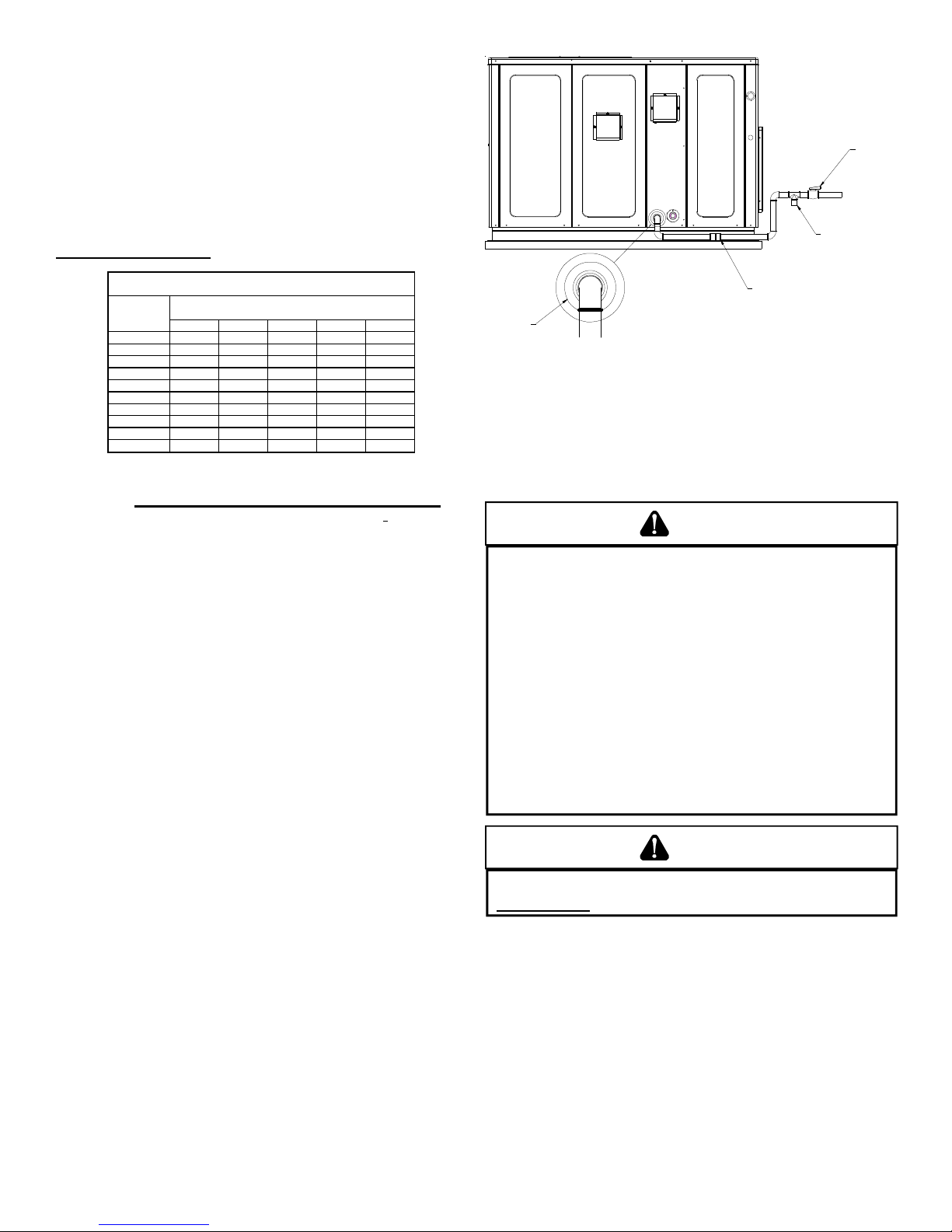
Natural Gas Connection
Natural Gas Capacity of Pipe
in Cubic Feet of Gas Per Hour (CFH)
Length of
Pipe in Feet
10 132 278 520 1050 1600
20 92 190 350 730 1100
30 73 152 285 590 980
40 63 130 245 500 760
50 56 115 215 440 670
60 50 105 195 400 610
70 46 96 180 370 560
80 43 90 170 350 530
90 40 84 160 320 490
100 38 79 150 305 460
Pressure = .50 PSIG or less and Pressure Drop of 0.3" W.C. (Based
CFH =
Heatin
Refer to the Proper Piping Practice drawing for the general layout
at the unit. The following rules apply:
1. Use black iron pipe and fittings for the supply piping. The
use of a flex connector and/or copper piping is permitted
as long as it is in agreement with local codes.
2. Use pipe joint compound on male threads only. Pipe joint
compound must be resistant to the action of the fuel used.
3. Use ground joint unions.
4. Install a drip leg to trap dirt and moisture before it can enter
the gas valve. The drip leg must be a minimum of three
inches long.
5. Use two pipe wrenches when making connection to the gas
valve to keep it from turning.
6. Install a manual shut-off valve in a convenient location
(within six feet of unit) between the meter and the unit.
7. Tighten all joints securely.
8. The unit must be connected to the building piping by one
of the following methods:
• Rigid metallic pipe and fittings
• Semirigid metallic tubing and metallic fittings (Aluminum
alloy tubing must not be used in exterior locations)
• Listed gas appliance connectors used in accordance with
the terms of their listing that are completely in the same
room as the equipment
• In the prior two methods above the connector or tubing
must be protected from physical and thermal damage.
Aluminum alloy tubing and connectors must be coated to
protect against external corrosion when in contact with
masonry, plaster or insulation or are subject to repeated
wettings by liquids (water - not rain water, detergents or
sewage)
Nominal Black Pipe Size (inches)
1/2 3/4
on 0.60 S
1
ecific Gravity Gas
1 1/4 1 1/2
BTUH Furnace Input
Value of Gas (BTU/Cubic Foot
MANUAL
SHUT-OFF
VALVE
DRIP LEG
GROUND JOINT UNION
(INSTALLED AHEAD OF GAS VALVE)
GROMMET
Proper Piping Practice
NOTE: The unit gas supply entrance is factory sealed with plugs.
Keep plugs in place until gas supply is ready to be installed. Once
ready, replace the plugs with the supplied grommets and install gas
supply line.
GAS PIPING CHECKS
CAUTION
T
O PREVENT PROPERTY DAMAGE OR PERSONAL INJURY DUE TO FIRE, THE
FOLLOWING INSTRUCTIONS MUST BE PERFORMED REGARDING GAS
CONNECTIONS AND PRESSURE TESTING:
•
HE UNIT AND ITS GAS CONNECTIONS MUST BE LEAK TESTED BEFORE
T
PLACING IN OPERATION.
FIRE, NEVER USE A MATCH OR OPEN FLAME TO TEST FOR LEAKS.
EXCEED SPECI FIED PRESSURES FOR TESTI NG.
DAMAGE GAS VALV E AND CAUSE OVERFIRING WHICH MAY RESULT IN
PREMATURE HEAT EXCHANGE FAILURE.
HIS UNIT AND ITS SHUT-OFF VALVE MUST BE DISCONNECTED FROM
•
T
THE GAS SUPPLY DURING ANY PRESSURE TESTING OF THAT SYSTEM AT
TEST PRESSURES IN EXCESS OF 1/2
•
HIS UNI T MUST BE ISOLA TED FROM THE GAS SUPPLY SYS TEM BY
T
CLOSING ITS MANUAL SHUT-OFF VALVE DURING ANY PRESSURE
TESTING OF THE GAS SUPPLY PIPING SYSTEM AT TEST PRESSURES
EQUAL TO OR LESS THAN 1/2
BECAUSE OF THE DANGER OF EXPLOSION OR
N
IGHER PRESSURE MAY
H
(3.48 KPA).
PSIG
(3.48 KPA).
PSIG
EVER
WARNING
O AVOID PROPERTY DAMAGE OR PERSONAL INJURY
T
NO OPEN FLAME IN THE VICINITY DURING AIR BLEEDING.
There will be air in the gas supply line after testing for leaks
on a new installation. Therefore, the air must be bled from the
line by loosening the ground joint union until pure gas is
expelled. Tighten union and wait for five minutes until all gas
has been dissipated in the air. Be certain there is no open
flame in the vicinity during air bleeding procedure. The unit is
placed in operation by closing the main electrical disconnect
switch for the unit.
, BE SURE THERE IS
7
Page 8
PROPANE GAS INSTALLATIONS
WARNING
O AVOID PROPERTY DAMAGE, PERSONAL INJURY OR DEATH DUE TO FIR E
T
OR EXPLOSION CAUSED BY A PROPANE GAS LEAK, INSTALL A GAS
DETECTING WARNING DEVICE.
OF ODORANT IN PROPANE GAS, A GAS DETECTING WARNING DEVICE
IS THE ONLY RELIABLE WAY TO DETECT A PROPANE GAS LEAK.
ONTACT A LOCAL PROPANE GAS SUPPLIER ABOUT INSTALLING A
C
GAS DETECTING WARNING DEVICE.
INCE RUST CAN REDUCE THE LEVEL
S
IMPORTANT NOTE: Propane gas conversion kits must be
installed to convert units to propane gas.
All propane gas equipment must conform to the safety
standards of the National Board of Fire Underwriters (See NBFU
Manual 58).
For satisfactory operation, propane gas supply pressure must
be within 9.7 - 10.3 inches W.C. at the manifold with all gas
appliances in operation. Maintaining proper gas pressure
depends on three main factors:
1. Vaporization rate, which depends on (a) temperature of the
liquid, and (b) wetted surface area of the container or
containers.
2. Proper pressure regulation.
3. Pressure drop in lines between regulators, and between
second stage regulator and the appliance. Pipe size
required will depend on length of pipe run and total load of
all appliances.
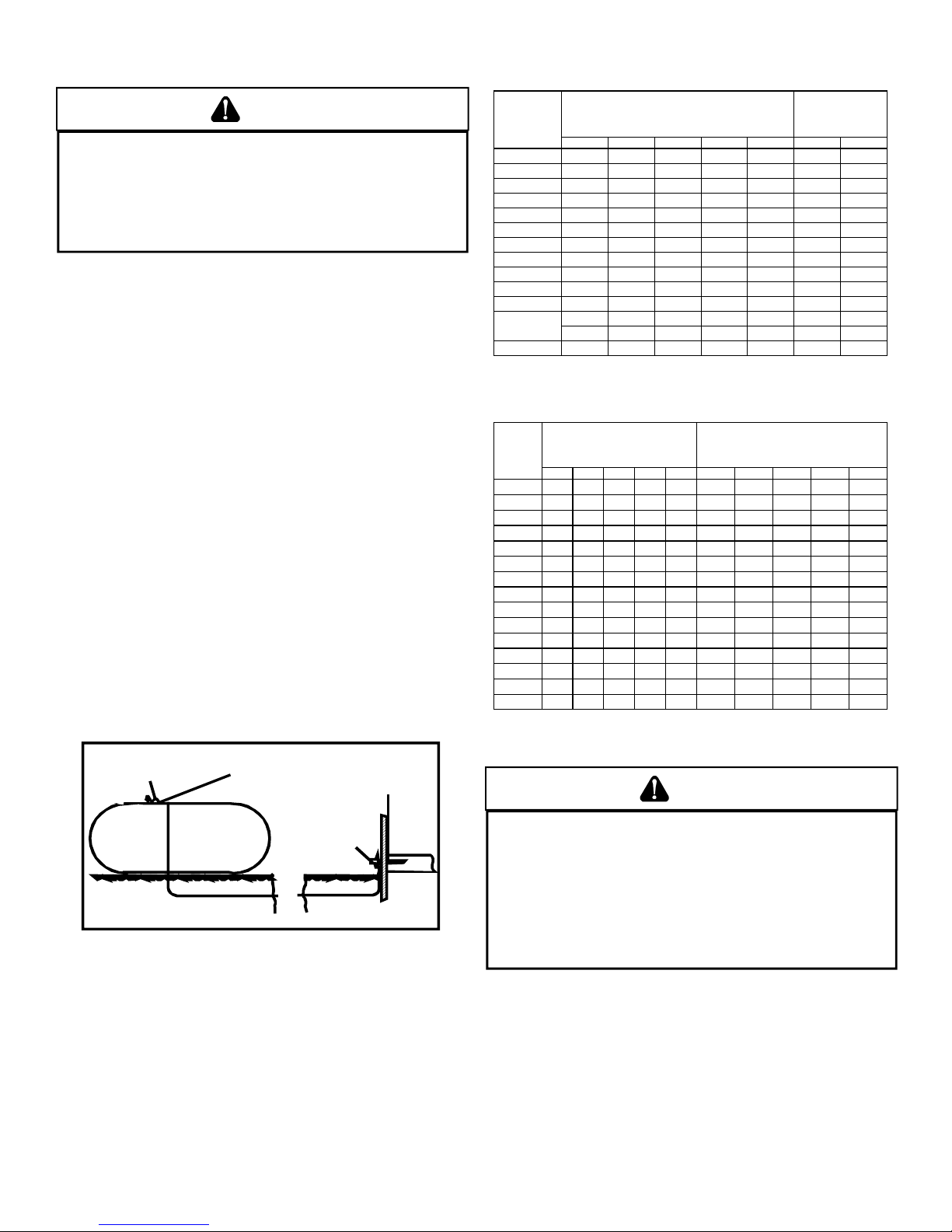
TANKS AND PIPING
Complete information regarding tank sizing for vaporization,
recommended regulator settings and pipe sizing is available
from most regulator manufacturers and propane gas suppliers.
Since propane gas will quickly dissolve white lead or most
standard commercial compounds, special pipe dope must be
used. Shellac base compounds resistant to the actions of
liquefied petroleum gases such as Gasolac®, Stalactic®,
Clyde’s® or John Crane® are satisfactory.
See below for typical propane gas piping.
First Stage
Regulator
5 to 15 PSIG
(20 PSIG Max.)
Continuous
11" W.C.
Sizing Between First and Second S tage Regulator
Maximum Propane Capacities listed a re based on 1 PSIG Pressure Drop at 10
PSIG Setting. Capacities in 1,000 BTU/HR
PIPE OR
TUBING
LENGTH,
FEET
30 309 700 1,303 2,205 3,39 4 1,843 3,854
40 265 599 1,115 1,887 2,90 4 1,577 3,298
50 235 531 988 1, 672 2,574 1,398 2, 923
60 213 481 896 1, 515 2,332 1,267 2, 649
70 196 446 824 1, 394 2,146 1,165 2, 437
80 182 412 767 1, 297 1,996 1,084 2, 267
90 171 386 719 1, 217 1,873 1,017 2, 127
100 161 365 679 1,149 1,769 96 1 2,009
150 130 293 546 923 1,42 1 772 1,613
200 111 251 467 790 1,21 6 660 1,381
250 90 222 414 700 1,078 585 1,224
300 89 201 378 634 976 530 1,109
350 82 185 345 584 898 488 1,020
400 76 172 321 543 836 454 949
To convert to Capacities at 15 PSI G Settings -- Multiply by 1.130
To convert to Capacities at 5 PSIG Settings -- Multiply by 0.879
Sizing Betwe en Single or Secon d Stage Regulato r and Appliance*
Maximum Pro pane Capacitie s Listed are Bas ed on 1/2" W.C. Pressure Drop at
11" W.C. Setting. Capacities in 1,000 BTU/HR
PIPE OR
TUBING
LENGTH,
FEET
10 49 110 206 348 539 291 608 1,146 2,353 3,525
20 34 76 141 239 368 200 418 788 1,617 2,423
30 27 61 114 192 296 161 336 632 1,299 1,946
40 23 52 97 164 253 137 284 541 1,111 1,665
50 20 46 86 146 224 122 255 480 985 1,476
60 19 42 78 132 203 110 231 436 892 1,337
80 16 36 67 113 174 94 198 372 764 1,144
100 14 32 59 100 154 84 175 330 677 1,014
125 12 28 52 89 137 74 155 292 600 899
150 11 26 48 80 124 67 141 265 544 815
200 10 22 41 69 106 58 120 227 465 697
250 9 19 36 61 94 51 107 201 412 618
300 8 18 33 55 85 46 97 182 374 560
350 7 16 30 51 78 43 89 167 344 515
400 7 15 28 47 73 40 83 156 320 479
*DATA IN ACCORDANCE WITH NFPA PAMPHLET NO. 54
TUBING SIZE, O.D., TYPE L
3/8" 1/2" 5/8" 3/4" 7/8" 1/2" 3/4" 1" 1-1/4" 1-1/2"
TUBING SIZE, O.D., TYPE L
3/8" 1/2" 5/8" 3/4" 7/8" 1/2" 3/4"
NOMINAL PIPE SIZE,
NOMINAL PIPE SIZE,
SCHEDULE 40
SCHEDULE 40
Table 3 - Propane Gas Pipe Sizing
WARNING
200 PSIG
Maximum
Second Stage
Regulator
Typical Propane Gas Piping
T
O PREVENT PROPERTY DAMAGE OR SERIOUS PERSONAL INJURY DUE TO
FIRE OR EXPLOSION CAUSED BY A PROPANE GAS LEAK, INSTALL A GAS
DETECTING WARNING DEVICE.
F THE PROPANE GAS UNIT IS INSTALLED IN AN EXCAVATED AREA OR A
I
CONFINED SPACE, A WARNING DEVICE IS REQUIRED DUE TO:
•
ROPANE GAS IS HEAVIER THAN AIR AND ANY LEAKING GAS CAN
P
SETTLE IN ANY LOW AREAS OR CONFINED SPACES.
•
ROPANE GAS ODORANT MAY FADE, MAKING THE GAS UNDETECTABLE
P
EXCEPT WITH A WARNING DEVICE.
ELECTRICAL WIRING
THERMOSTAT L OCATION
Mount the thermostat approximately five feet above the floor,
in an area that has an inside, vibration-free wall and has good
air circulation.
8
Page 9
Movement of air must not be obstructed by furniture, door,
draperies, etc. The thermostat must not be mounted where it
will be affected by drafts, hot or cold water pipes or air ducts in
walls, radiant heat from fireplace, lamps, the sun, television,
etc. Consult the Instruction Sheet packaged with thermostat
for mounting instructions.
All units have one stage of heating and one stage of
mechanical cooling. Units which will have economizers may
use thermostats with one or two stages of cooling.
The units are designed for operation on 60 hertz current and
at voltages as shown on the rating plate. All internal wiring in
the unit is complete. It is necessary to bring in the power supply
to the contactor as shown on the unit wiring diagram which is
supplied with each unit. 24 volt wiring must be connected
between the unit control panel and the room thermostat.
CAUTION
O PREVENT IMPROPER AND DANGEROUS OPERATION DUE TO WIRING ERRORS,
T
LABEL ALL WIRES PRIOR TO DISCONNECTION WHEN SERVICING CONTROLS.
ERIFY PROPER OPERATION AFTER SERVICING.
V
For unit protection, use a time delay fuse or HACR circuit
breaker that is in excess of the circuit ampacity, but less than
or equal to the maximum overcurrent protection device. DO
NOT EXCEED THE MAXIMUM OVERCURRENT DEVICE SIZE
SHOWN ON UNIT DATA PLATE.
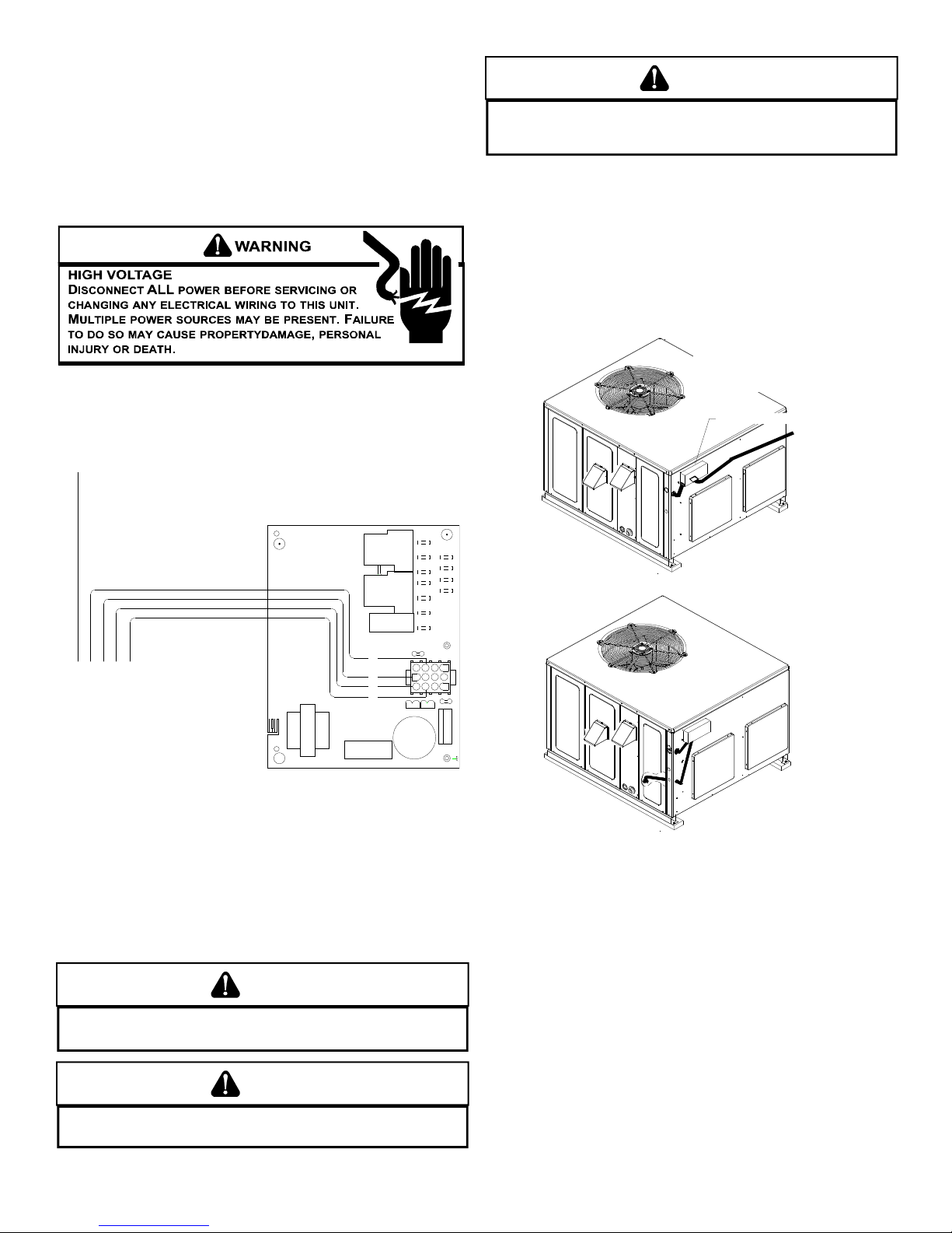
All line voltage connections must be made through
weatherproof fittings. All exterior power supply and ground
wiring must be in approved weatherproof conduit. Low voltage
wiring from the unit control panel to the thermostat requires
coded cable. See below for ground level and rooftop wiring.
Note:Junction box location
shown is optional and is
for illustration purposes only.
JUNCTION BOX
1068-83-400A
B18099-18
K4
K3
WYR
C
G
LOW VOLTAGE
CONNECTOR
MODEL
1068-400
24VAC 50/60Hz 400mA MAX.
ANSI Z21.20 AUTOMATIC IGNITION SYSTEM
COMPRESSOR
BREAK FOR TWO STAGE
T2
K2
K1
R
12
12
12
11
Y
W
G
11
11
10
10
10
F1
FUSE 3 AMP MAX
T1
C22
Low Voltage Wiring
Refer to the unit wiring diagram for electrical connections.
When installed, the unit must be electrically grounded in
accordance with local codes or in the absence of local codes,
with the National Electrical Code, ANSI/NFPA No. 70, and/or
the CSA C22.1 Electrical Code. Ensure low voltage
connections are waterproof.
COOL
L2L2L2L2
L1 HEATUNUSED
L1DI
9FS6
3
3
659
9
6
3
2
2
8
8
5
7
4
1
1
7
4
12
7
4
P1
ECON
120
135
P3
150
P2
SPEED-UP
Electrical Power Directly To Junction Box
Electrical Power Routed Through Bottom of Unit
Typical Electrical Wiring Unit Voltage
UNIT V OLTAGE
The unit transformer is factory connected for 230V operation.
If the unit is to operate on 208V, reconnect the transformer
primary lead as shown on the unit wiring diagram.
WARNING
O AVOID THE RISK OF ELECTRICAL SHOCK, WIRING TO THE UNIT MUST BE
T
POLARIZED AND GROUNDED.
CAUTION
O AVOID PROPERTY DAMAGE OR PERSONAL INJURY DUE TO FIRE, USE
T
ONLY COPPER CONDUCTORS.
HEAT A NTICIPATOR S ETTING
The heat anticipator is to be set by measuring the load
(amperage) at the “R” circuit. Follow the instructions provided
by the thermostat for more details.
9
Page 10
G
Y
R
W
R
Unit
W
Y
G
From
Typical Thermostat and Unit 24 V Wiring Hookup
CIRCULATING AIR AND FILTERS
AIRFLOW C ONVERSION
Units can easily be converted from horizontal to downdischarge airflow delivery. In down-discharge or high static
installations, the installer should measure the total external
static and review the blower performance charts before
performing the installation. In some installations it will be
necessary to change the blower speed to provide proper air
flow.
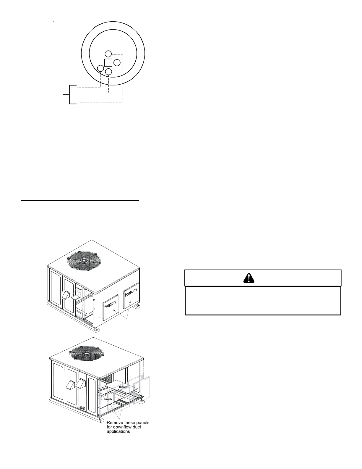
Horizontal Air Flow (Applies to 3 phase models)
Single phase models are shipped without horizontal duct
covers. If needed, these kits may be ordered through
Goodman’s Service Parts department.
Remove supply and return duct covers which are attached to
the unit as shown below.
Down Discharge Applications
Cut insulation around bottom openings and remove panels
from the bottom of the unit, saving the screws holding the
panels in place.
NOTE: Single phase models require installation of horizontal
duct kit #20464501PDGK (medium chassis) and
#20464502PDGK (large chassis).
DUCTWORK
Duct systems and register sizes must be properly designed
for the C.F.M. and external static pressure rating of the unit.
Ductwork should be designed in accordance with the
recommended methods of Air Conditioning Contractors of
America Manual D (Residential) or Manual Q (Commercial).
All ductwork exposed to the outdoors must include a
weatherproof barrier and adequate insulation.
A duct system should be installed in accordance with
Standards of the National Board of Fire Underwriters for the
Installation of Air Conditioning, Warm Air Heating and
Ventilating Systems. Pamphlets No. 90A and 90B.
The supply duct from the unit through a wall may be installed
without clearance. However, minimum unit clearances as
shown in the appendix must be maintained. The supply duct
should be provided with an access panel large enough to
inspect the air chamber downstream of the heat exchanger.
A cover should be tightly attached to prevent air leaks.
For duct flange dimensions on the unit refer to the Unit
Dimension illustration in the appendix.
For down-discharge applications, the ductwork should be
attached to the roof curb prior to installing the unit. Ductwork
dimensions are shown in the roof curb installation manual.
If desired, supply and return duct connections to the unit may
be made with flexible connections to reduce possible unit
operating sound transmission.
Remove these covers
for horizontal duct
applications
FILTERS
CAUTION
T
O PREVENT PROPERTY DAMAGE DUE TO FIRE AND LOSS OF
EQUIPMENT EFFICIENCY OR EQUIPMENT DAMAGE DUE TO DUST AND LINT
BUILD UP ON INTERNAL PARTS, NEVER OPERATE UNIT WITHOUT AN AIR
FILTER INSTALLED IN THE RETURN AIR SYSTEM.
Even though a return air filter is not supplied with this unit,
there must be a means of filtering all return air. All units may
be externally filtered.
Refer to the unit filter size chart in the appendix for filter size
information.
Filters installed external to the unit should be sized in
accordance with their manufacturer recommendations. A
throwaway filter must be sized for a maximum face velocity of
300 feet per minute.
Filter Installation
Important: When installing a filter, the air flow arrows on the
filter must point toward the circulator blower.
Duct Cover Installation
10
Page 11
VENTING
NOTE: Venting is self-contained. Do not modify or block.
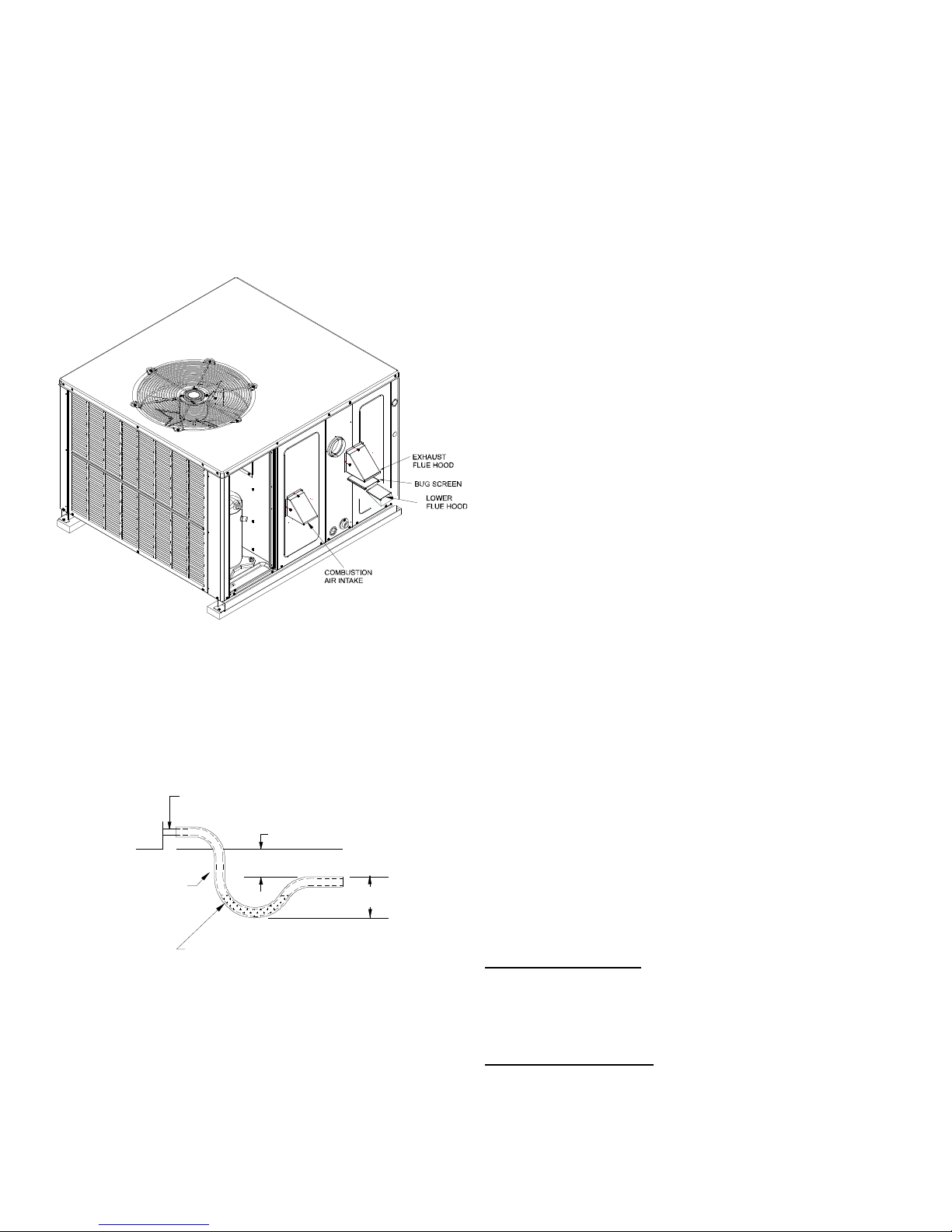
FLUE H OOD I NSTALLATION
Install the exhaust flue hood and combustion air intake hood
prior to operation of the unit.
To install the flue hood cover, please refer to IO-653*, included
in the flue hood assembly box located in the blower
compartment.
2. The spark igniter and gas valve energizes for 7 seconds.
NOTE: The igniter produces a very intense electrical spark
that ignites the gas.
3. The 30-second HEAT FAN ON delay time begins.
4. The unit delivers heat to the conditioned space until the
thermostat is satisfied.
5. The gas valve deenergizes. The induced draft blower
continues operation for a 29-second post-purge.
6. Ignition control begins timing the HEAT FAN OFF delay.
There is an adjustable HEAT FAN OFF delay of
approximately 120/135/150 seconds (factory set at 150).
After the HEAT FAN OFF delay time has elapsed, the blower
will deenergize. This allows any additional heat in the
heat exchanger to be transferred to the conditioned space.
COOLING
1. Thermostat calls for cooling. The compressor and outdoor
fan are energized.
2. Approximately seven seconds later, the indoor fan starts.
3. The unit will deliver cooling to the conditioned space until
the thermostat is satisfied.
4. The compressor and outdoor fan will be de-energized
when the thermostat opens.
5. The indoor fan continues to run for approximately 60
seconds after the thermostat is satisfied. This allows
additional cooling from the indoor coil to be transferred to
the conditioned space. Then, the indoor fan stops.
Flue Hood and Bug Screen Installation
CONDENSATE DRAIN
CONDENSATE D RAIN C ONNECTION
A 3/4” NPT drain connection is supplied for condensate piping. An
external trap must be installed for proper condensate drainage.
NOTE: Maximum torque is 10 in-lbs.
DRAIN
CONNECTION
UNIT 2" MINIMUM
FLEXIBLE
TUBING-HOSE
OR PIPE
A POSITIVE LIQUID
SEAL IS REQUIRED
3" MINIMUM
Drain Connection
NORMAL SEQUENCES OF OPERATION
HEATING
This unit is equipped with an ignition control that automatically
lights the main burner. DO NOT attempt to light the main
burners by any other method.
1. Thermostat calls for heat. The induced draft blower
energizes for a 15-second pre-purge.
NOTE: A 180-second anti-short cycle is integral to the control and
prevents recycling of the compressor.
FAN ONLY
1. Thermostat calls for FAN ONLY by energizing “G”.
2. Approximately seven seconds later, the indoor fan starts.
3. The indoor fan continues to run for approximately 60
seconds after “G” is de-energized.
STARTUP, ADJUSTMENTS, AND CHECKS
HEATING S TARTUP
This unit is equipped with an electronic ignition device to
automatically light the main burners. It also has a power vent
blower to exhaust combustion products.
On new installations, or if a major component has been
replaced, the operation of the unit must be checked.
Check unit operation as outlined in the following instructions.
If any sparking, odors, or unusual sounds are encountered,
shut off electrical power and recheck for wiring errors, or
obstructions in or near the blower motors. Duct covers must
be removed before operating unit.
Heat Anticipator Setting
Set the heat anticipator on the room thermostat to 0.4 amps
to obtain the proper number of heating cycles per hour and to
prevent the room temperature from overshooting the room
thermostat setting.
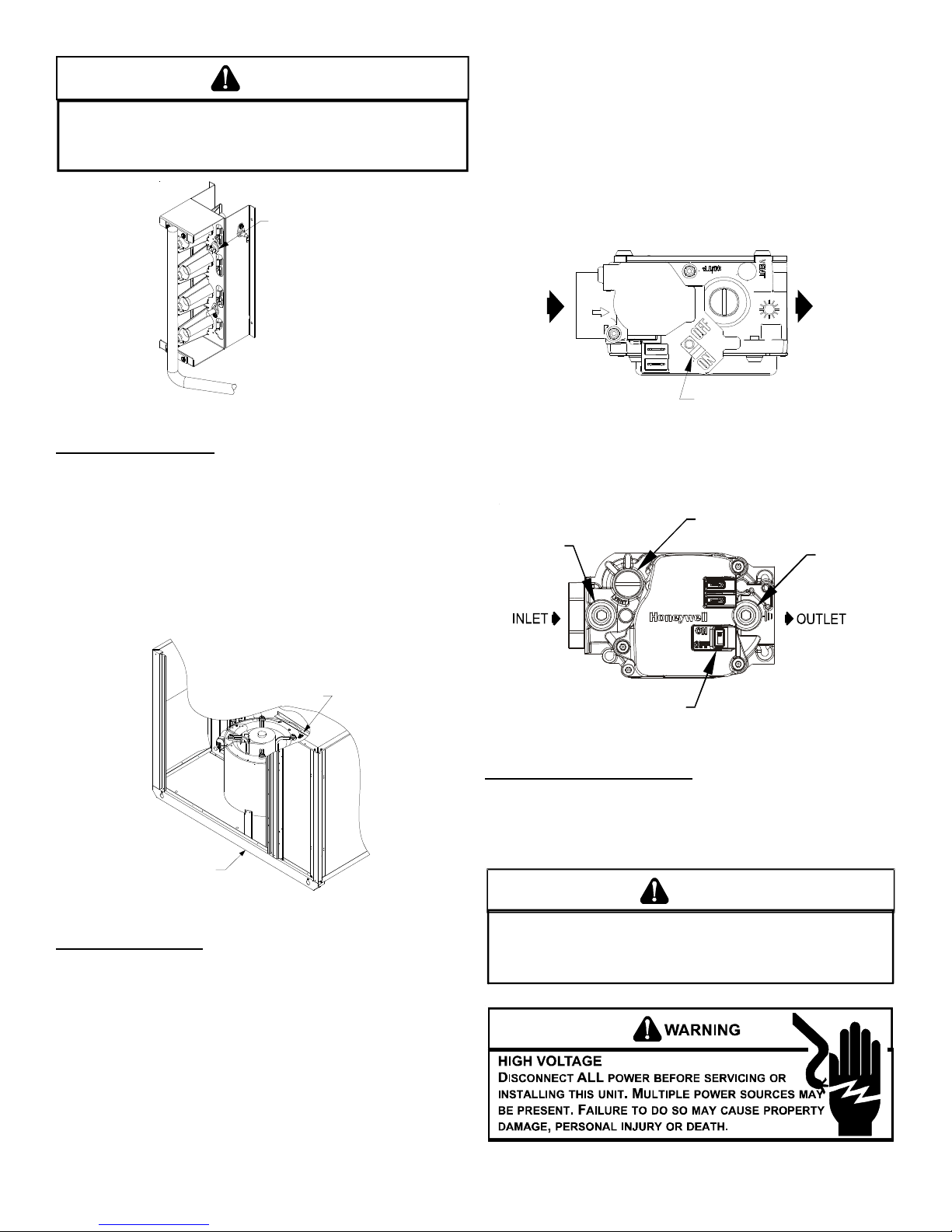
Rollout Protection Control
The rollout protection device opens, cutting power to the gas
valve, if the flames from the burners are not properly drawn
into the heat exchanger. The rollout protection device is located
on the burner bracket. The reason for elevated temperatures
at the control should be determined and repaired prior to
resetting this manual reset control.
11
Page 12
WARNING
T
O AVOID PROPERTY DAMAGE, PERSONAL INJURY OR DEATH DUE TO FIRE
T
OR EXPLOSION, A QUALIFIED SERVICER MUST INVESTIGATE THE REASON FOR
THE ROLLOUT PROTECTION DEVICE TO OPEN BEFORE MANUALLY RESETTING
THE ROLLOUT PROTECTION DEVICE.
Rollout Protection
8. Smell for gas, including near the ground. This is important
because some types of gas are heavier than air. If you
have waited five minutes and you do smell gas,
immediately follow the warnings on page 3 of this manual.
If having waited for five minutes and no gas smell is noted,
move the gas control valve switch to the ON position.
9. Replace the heat exchanger door on the side of the unit.
10. Open the manual gas valve external to the unit.
11. Turn on the electrical power supply to the unit.
12. Set the thermostat to desired setting.
Rollout Protection on Burner Bracket
Secondary Limit Control
The secondary limit control is located on the top of the blower
scroll assembly. This control opens when elevated
temperatures are sensed. Elevated temperatures at the
control are normally caused by blower failure. The reason for
the opening should be determined and repaired prior to
resetting.
If the power to the unit is interrupted during the heating cycle,
it may cause the secondary limit to trip. Once the blower
compartment temperature drops below the limit reset
temperature, the limit will automatically reset.
Secondary
Control Lim it
INLET
Inlet
Pressure
Ta p
OUTLE
Gas Valve
On/Off
Selector
Switch
White-Rodgers 36G22
Pressure Regulator
(under cap screw)
Outlet
Pressure
Ta p
Gas Valve On/Off
Selector Switch
Honeywell Model VR8215 (Single-Stage)
Back of Unit
Secondary Limit Control
Pre-Operation Checks
1. Close the manual gas valve external to the unit.
2. Turn off the electrical power supply to the unit.
3. Set the room thermostat to its lowest possible setting.
4. Remove the heat exchanger door on the side of the unit by
removing screws.
5. This unit is equipped with an ignition device which
automatically lights the main burner. DO NOT try to light
burner by any other method.
6. Move the gas control valve switch to the OFF position. Do
not force.
7. Wait five minutes to clear out any gas.
Gas Supply And Manifold Check
Gas supply pressure and manifold pressure with the burners
operating must be as specified on the rating plate.
GAS SUPPLY PRESSURE MEASUREMENT
CAUTION
TO
PREVENT UNRELIA BLE OPERATION OR EQUIPMENT DAMAGE, THE
NLET GAS SUPPLY PRESSURE MUST BE AS SPECIFIED ON THE UNIT
I
RATING PLATE WITH ALL OTHER HOUSEHOLD GAS FIRED APPLIANCES
OPERATING
.
12
Page 13

The line pressure supplied to the gas valve must be within the
range specified in the chart on the next page. The supply pressure
can be measured at the gas valve inlet pressure tap or at a hose
fitting installed in the gas piping drip leg. The supply pressure
must be measured with the unit OFF. To measure inlet pressure,
use the following procedure.
Gas Valve
On/Off
OUTLET
Pressure Regulator
Adjustment
(Under Cap Screw)
White-Rodgers Model 36G22
Selector
Switch
Outlet Pressure
Inlet Pressure
Tap
INLET
Tap
Pressure Regulator
Inlet
Pressure
Ta p
(under cap screw)
Outlet
Pressure
Ta p
8. Measure the gas supply pressure with burners firing. Adjust
supply pressure using the Inlet Gas Supply Pressure table
shown below. If supply pressure reading differs from the
table, make necessary adjustments to pressure regulator,
gas piping size, etc., and/or consult with local gas utility.
Inlet Gas Supply Pressure
Natural Gas
Propane Gas
9. Turn OFF all electrical power and gas supply to the system.
10.Remove the manometer hose from the hose barb fitting
or inlet pressure boss.
11.Replace inlet pressure tap:
a. Honeywell VR8215 valve:
Remove the 1/8” NPT hose barb fitting from the inlet
pressure tap. Replace the inlet pressure boss plug and
seal with a high quality thread sealer.
b. White-Rodgers 36G22 valve:
Turn inlet pressure test screw in to seal pressure port
(clockwise, 7 in-lb minimum).
12.Retest for leaks. If bubbles form, SHUT DOWN GAS AND
REPAIR LEAKS IMMEDIATELY.
13.Turn ON electrical power and gas supply to the system.
14.Turn valve switch ON.
Minimum:5.0" W.C. Maximum :10.0" W.C.
Minimum:11.0" W.C. Maximum :13.0" W.C.
GAS MANIFOLD P RESSURE MEASUREMENT AND A DJUSTMENT
Gas Valve On/Off
Selector Switch
Honeywell Model VR8215 (Single-Stage)
1. Turn OFF gas to furnace at the manual gas shutoff valve
external to the furnace.
2. Turn OFF all electrical power to the system.
3. Inlet pressure tap connections:
a. Honeywell VR8215 Valve:
Remove the inlet pressure boss plug. Install an 1/8” NPT
hose barb fitting into the outlet pressure tap.
b. White-Rodgers 36G22 valve:
Back inlet pressure test screw (inlet pressure boss) out
one turn (counterclockwise, not more than one turn).
4. Attach a hose and manometer to the outlet pressure barb
fitting (Honeywell valve) or inlet pressure boss (WhiteRodgers valve).
5. Turn ON the gas supply.
6. Turn On power and close thermostat “R” and “W” contacts
to provide a call for heat.
7. Using a leak detection solution or soap suds, check for
leaks at outlet pressure boss plug (Honeywell valve) or
screw (White-Rodgers valve). Bubbles forming indicate a
leak. SHUT OFF GAS AND REPAIR ALL LEAKS
IMMEDIATELY!
CAUTION
TO
PREVENT UNRELIA BLE OPERATION OR EQUIPMENT DAMAGE, THE
NLET GAS SUPPLY PRESSURE MUST BE AS SPECIFIED ON THE UNIT
I
RATING PLATE WITH ALL OTHER HOUSEHOLD GAS FIRED APPLIANCES
OPERATING
This valve is shipped from the factory with the regulator preset
(see control label).
Consult the appliance rating plate to ensure burner manifold pressure is as specified. If another outlet pressure is required, follow
these steps.
1. Turn OFF gas to furnace at the manual gas shutoff valve
2. Turn OFF all electrical power to the system.
3. Outlet pressure tap connections:
a. Honeywell VR8215 valve:
b. White-Rodgers 36G22 valve:
4. Attach a hose and manometer to the outlet pressure barb
5. Turn ON the gas supply.
.
external to the furnace.
Remove the outlet pressure boss plug. Install an 1/8”
NPT hose barb fitting into the outlet pressure tap.
Back outlet pressure test screw (outlet pressure boss)
out one turn (counterclockwise, not more than one turn).
fitting (Honeywell valve) or outlet pressure boss (WhiteRodgers valve).
13
Page 14

6. Turn ON power and close thermostat “R” and “W” contacts
to provide a call for heat.
7. Using a leak detection solution or soap suds, check for
leaks at outlet pressure boss plug (Honeywell valve) or
screw (White-Rodgers valve). Bubbles forming indicate a
leak. SHUT OFF GAS AND REPAIR ALL LEAKS
IMMEDIATELY!
8. Measure the gas manifold pressure with burners firing.
Adjust manifold pressure using the Manifold Gas Pressure
table shown below.
Manifold Gas Pressure
Natural Gas 3.5" w.c.
Propane Gas 10.0" w.c.
9. Remove regulator cover screw from the outlet pressure
regulator and turn screw clockwise to increase pressure
or counterclockwise to decrease pressure. Replace
regulator cover screw.
10.Turn OFF all electrical power and gas supply to the system.
11.Remove the manometer hose from the hose barb fitting
or outlet pressure boss.
12.Replace outlet pressure tap:
a. Honeywell VR8215 valve:
Remove the 1/8” NPT hose barb fitting from the outlet
pressure tap. Replace the outlet pressure boss plug and
seal with a high quality thread sealer.
b. White-Rodgers 36G22 valve: Turn outlet pressure test
screw in to seal pressure port (clockwise, 7 in-lb
minimum).
13. Turn ON electrical power and gas supply to the system.
14. Close thermostat contacts to provide a call for heat.
15.Retest for leaks. If bubbles form, SHUT OFF GAS AND
REPAIR ALL LEAKS IMMEDIATELY!
Gas Input (Natural Gas Only) Check
To measure the gas input use a gas meter and proceed as
follows:
1. Turn off gas supply to all other appliances except the unit.
2. With the unit operating, time the smallest dial on the meter
for one complete revolution. If this is a 2 cubic foot dial,
divide the seconds by 2; if it is a 1 cubic foot dial, use the
seconds as is. This gives the seconds per cubic foot of
gas being delivered to the unit.
3. INPUT=GAS HTG VALUE x 3600 / SEC. PER CUBIC FOOT
Example: Natural gas with a heating value of 1000 BTU per cubic
foot and 34 seconds per cubic foot as determined by Step 2, then:
Input = 1000 x 3600 / 34 = 106,000 BTU per Hour. NOTE:
BTU content of the gas should be obtained from the gas
supplier. This measured input must not be greater than
shown on the unit rating plate.
4. Relight all other appliances turned off in step 1. Be sure all
pilot burners are operating.
Main Burner Flame Check
Flames should be stable, soft and blue (dust may cause
orange tips but they must not be yellow) and extending directly
outward from the burner without curling, floating or lifting off.
Temperature Rise Check
Check the temperature rise through the unit by placing
thermometers in supply and return air registers as close to
the unit as possible. Thermometers must not be able to
sample temperature directly from the unit heat exchangers,
or false readings could be obtained.
1. All registers must be open; all duct dampers must be in
their final (fully or partially open) position and the unit
operated for 15 minutes before taking readings.
2. The temperature rise must be within the range specified
on the rating plate.
NOTE: Air temperature rise is the temperature difference between
supply and return air.
With a properly designed system, the proper amount of
temperature rise will normally be obtained when the unit is
operated at rated input with the recommended blower speed.
If the correct amount of temperature rise is not obtained, it
may be necessary to change the blower speed. A higher
blower speed will lower the temperature rise. A slower blower
speed will increase the temperature rise.
NOTE: Blower speed MUST be set to give the correct air temperature rise through the unit as marked on the rating plate.
External Static Pressure Check
The total external static pressure must be checked on this unit to
determine if the airflow is proper.
Blower Speed Adjustments
WARNING
TO AVOID PERSONAL INJURY OR DEATH DUE TO ELECTRIC SHOCK, REMOVE
ELECTRICAL POWER FROM THE UNIT BEFORE CHANGING SPEED TAPS ON THE
BLOWER MOTOR.
Refer to the wiring diagram in the appendix to verify speed tap
settings.
For models equipped with PSC type motors, blower speeds
are to be changed at the ignition control board. Both heat
speed and cool speed terminals are supplied on the board
along with two unused motor lead terminals.
Some models are equipped with EEM motors. EEM motors are
constant torque motors with very low power consumption. This
motor is energized by 24V. Adjust the CFM for the unit by changing
the 24V low voltage leads to the speed terminal block on the
motor.
Heating-White Lead Cooling-Yellow Lead
T1 - Low Speed T4 - Low Speed
T2 - Medium Speed T5 - High Speed
T3 - High Speed
NOTE: Heating airflow must be adjusted to provide the temperature
rise shown on rating plate.
Limit Check
Check limit control operation after 15 minutes of operation by
blocking the return air grille(s).
1. After several minutes the main burners must go OFF.
Blower will continue to run.
2. Remove air restrictions and main burners will relight
after a cool down period of a few minutes.
14
Page 15

Adjust the thermostat setting below room temperature.
1
2
3
10
11
12
9
6
23
6
5
8
9
11
12
L2
L2L2
L2
D1
L1
L1 UNUSED
HEAT
COOL
FS
K2
K1
R8
R10
R3
K4
K3
R31
LED
1
0
6
8
-
8
3
-
4
0
0
A
C27
D3
R38
D9
D10
R34
R35
R4
R11
R42
D12
R36
D11
D14
C20
Z
1
R29
R22
C13
R25
D5
D7
1. Main burners must go OFF.
2. Circulating Air Blower will continue to run for 120, 135 or
150 seconds, depending on the setting.
Control Board (Top)
NOTE: If necessary, adjust fan OFF delay settings to obtain satis-
factory comfort level.
Unit Shutdown
1. Set the thermostat to lowest setting.
2. Turn off the electrical power supply to the unit.
3. Remove the heat exchanger door on the side of the unit by
removing screws.
4. Move the gas control valve switch to the OFF position. Do
not force.
5. Close manual gas shutoff valve external to the unit.
6. Replace the heat exchanger door on the unit.
7. If cooling and/or air circulation will be desired, turn ON the
electrical power.
COOLING S TARTUP
NOTE: Check all manual reset limit controls in heating circuit if
cooling mode does not operate.
Compressor Protection Devices
The compressor includes components which are designed
to protect the compressor against abnormal operating
conditions.
WARNING
O PREVENT PERSONAL INJURY OR DEATH, ALWAYS DISCONNECT ELECTRICAL
T
POWER BEFORE INSPECTI NG OR SERVICING THE UN IT.
PROTECTION DEVICES RESET AUTOMATICALLY, ENERGIZING THE CONTACTOR
AND OUTDOOR FAN.
Refrigerant Charge Check
After completing airflow measurements and adjustments the
unit’s refrigerant charge must be checked. The unit comes factory
charged, but this charge is based on 325 CFM per ton and
minimum ESP per AHRI test conditions (generally between .15
-.28 ESP). When air quantity or ESP is different than above,
the refrigerant charge must be adjusted to the proper amount.
ALL COMPRESSOR
All package units with fixed orifice devices are charged using
the super heat method at the compressor suction line.
After superheat is adjusted it is recommended to check unit
sub-cooling at the condenser coil liquid line out. For charge
adjustments, see superheat and sub-cooling charts shown for
each model.
Designsuperheat&su b c o ol in g@95°Foutdoor
Models#Superheat ±2°F Subcooling±3°F
GPG1324***M
GPG1330***M
GPG1336***M
715
615
79
GPG1342***M 912
GPG1348***M
GPG1360***M
Cooling Operation
NOTE: Mechanical cooling cannot be reliably provided at ambient
temperatures below 50° F.
1. Turn on the electrical power supply to the unit.
2. Place the room thermostat selector switch in the COOL
position (or AUTO if available, and if automatic changeover
from cooling to heating is desired).
3. Set the room thermostat to the desired temperature.
13 9
10 9
TROUBLESHOOTING
IGNITION CONTROL E RROR CODES
The following presents probable causes of questionable unit
operation. Refer to Diagnostic Indicator Chart for an
interpretation of the signal and to this section for an explanation.
Remove the control box access panel and note the number of
diagnostic LED flashes. Refer to Diagnostic Indicator Chart
for an interpretation of the signal and to this section for an
explanation.
ABNORMAL OPERATION - HEATING
Internal Control Failure
If the integrated ignition control in this unit encounters an
internal fault, it will go into a “hard” lockout and turn off the
diagnostic LED. If diagnostic LED indicates an internal fault,
check power supply to unit for proper voltage, check all fuses,
circuit breakers and wiring. Disconnect electric power for five
seconds. If LED remains off after restoring power, replace control.
External Lockout
An external lockout occurs if the integrated ignition control
determines that a measurable combustion cannot be established
within three (3) consecutive ignition attempts. If flame is not
established within the seven (7) second trial for ignition, the gas
valve is de-energized, 15 second inter-purge cycle is completed,
and ignition is reattempted. The control will repeat this routine
three times if a measurable combustion is not established. The
control will then shut off the induced draft blower and go into a
lockout state.
15
Page 16

If flame is established but lost, the control will energize the
circulator blower at the heat speed and then begin a new
ignition sequence. If flame is established then lost on
subsequent attempts, the control will recycle for four (4)
consecutive ignition attempts (five attempts total) before
locking out.
The diagnostic fault code is 1 flash for a lockout due to failed
ignition attempts or flame dropouts. The integrated control will
automatically reset after one hour, or it can be reset by removing
the thermostat signal or disconnecting the electrical power supply
for over five seconds. If the diagnostic LED indicates an external
lockout, perform the following checks:
• Check the supply and manifold pressures
• Check the gas orifices for debris
• Check gas valve for proper operation
• Check secondary limit
A dirty filter, excessive duct static, insufficient air flow, a
faulty limit, or a failed circulator blower can cause this
limit to open. Check filters, total external duct static,
circulator blower motor, blower motor speed tap (see
wiring diagram), and limit. An interruption in electrical
power during a heating cycle may also cause the
auxiliary limit to open. The automatic reset secondary
limit is located on top of the circulator blower assembly.
• Check rollout limit
If the burner flames are not properly drawn into the heat
exchanger, the flame rollout protection device will open.
Possible causes are restricted or blocked flue passages,
blocked or cracked heat exchanger, a failed induced
draft blower, or insufficient combustion air. The rollout
protection device is a manual reset limit located on the
burner bracket. The cause of the flame rollout must be
determined and corrected before resetting the limit.
• Check flame sensor
A drop in flame signal can be caused by nearly invisible
coating on the sensor. Remove the sensor and carefully
clean with steel wool.
• Check wiring
Check wiring for opens/shorts and miswiring.
Important: If you have to frequently reset your gas/electric
package unit, it means that a problem exists that should be
corrected. Contact a qualified servicer for further
information.
Pressure Switch Stuck Open
A pressure switch stuck open can be caused by a faulty
pressure switch, faulty wiring, a disconnected or damaged
hose, a blocked or restricted flue, or a faulty induced draft
blower.
If the control senses an open pressure switch during the prepurge cycle, the induced draft blower only will be energized. If
the pressure switch opens after ignition has begun the gas
valve is de-energized, the circulator blower heat off cycle
begins, and the induced draft blower remains on. The
diagnostic fault code is two flashes.
Pressure Switch Stuck Closed
A stuck closed pressure switch can be caused by a faulty
pressure switch or faulty wiring. If the control encounters a
pressure switch stuck closed, the induced draft blower remains
off. The diagnostic LED code for this fault is three (3) flashes.
Open Thermal Protection Device
If the primary limit switch opens, the gas valve is immediately
de-energized, the induced draft and air circulating blowers
are energized. The induced draft and air circulator blowers
remain energized until the limit switch recloses. The
diagnostic fault code for an open limit is four (4) flashes.
A primary limit will open due to excessive supply air
temperatures. This can be caused by a dirty filter, excessive
duct static, insufficient air flow, or a faulty limit. Check filters,
total external duct static, blower motor, blower motor speed
tap (see wiring diagram), and limit. This limit will automatically
reset once the temperature falls below a preset level.
Flame Detected with Gas Valve Closed
If flame is detected with the gas valve de-energized, the
combustion and air circulator blowers are energized. The
diagnostic fault code is five (5) flashes for this condition. The
control can be reset by removing the power supply to the unit
or it will automatically reset after one hour. Miswiring is the
probable cause for this fault.
ABNORMAL OPERATION - COOLING
Short Cycle Compressor Delay
The automatic ignition control has a built-in feature that
prevents damage to the compressor in short cycling
situations. In the event of intermittent power losses or
intermittent thermostat operation, the ignition control will delay
output to the compressor contactor for three minutes from the
time power is restored. (Compressor is off a total of three
minutes). The diagnostic LED will flash six (6) times to indicate
the compressor contactor output is being delayed.
NOTE: Some electronic thermostats also have a built-in
compressor short cycle timer that may be longer than the three
minute delay given above. If you are using an electronic thermostat
and the compressor has not started after three minutes, wait an
additional five minutes to allow the thermostat to complete its short
cycle delay time.
MAINTENANCE
Have the gas heating section of the unit checked at least
once a year before the heating season begins, to be sure that
the combustion air inlet and flue outlet hoods are not blocked
by debris, which would prevent adequate combustion air and
a properly operating vent system.
FILTER R EPLACEMENT OR CLEANING
A return air filter is not supplied with this unit; however, there
must be a means of filtering all of the return air. The filter(s)
may be located in the return air duct(s), or return air filter
grille(s). Consult with your installing dealer for the actual
location of the return air filter(s) for your unit.
Dirty filters are the most common cause of inadequate heating
or cooling performance. Filter inspection should be made at
least every two months; more often if necessary because of
local conditions and usage.
Dirty throwaway filters should be discarded and replaced with
a new, clean filter. Dirty permanent filters should be washed
with water, thoroughly dried and sprayed with a filter adhesive
before being reinstalled. (Filter adhesives may be found at
many hardware stores.) Permanent filters should last several
years. However, should one become torn or uncleanable, it
should be replaced.
16
Page 17

CABINET F INISH M AINTENANCE
Use a fine grade automotive wax on the cabinet finish to
maintain the finish’s original high luster. This is especially
important in installations with extended periods of direct
sunlight.
CLEAN OUTSIDE COIL (QUALIFIED SERVICER ONLY)
The coil with the outside air flowing over it should be inspected
annually and cleaned as frequently as necessary to keep the
finned areas free of lint, hair and debris.
CONDENSER, EVAPORATOR, AND I NDUCED DRAFT M OTORS
Bearings on the air circulating blower motor, condenser motor
and the combustion fan motor are permanently lubricated.
No additional oiling is required.
FLAME SENSOR (QUALIFIED SERVICER ONLY)
A drop in the flame current can be caused by a nearly invisible
coating on the flame sensor. This coating, created by the fuel
or combustion air supply, can be removed by carefully
cleaning the flame sensor with steel wool.
NOTE: After cleaning, the microamp signal should be stable and
in the range of 4 - 6 microamps DC.
Flame
Sensor
CLEANING FLUE PASSAGES (QUALIFIED SERVICER ONLY)
1. Shut off electric power and gas supply to the unit.
2. Remove burner assembly by disconnecting the gas line
and removing the manifold bracket from the partition panel.
3. Remove the flue from the induced draft blower and the
collector box cover from the partition panel.
4. The primary heat exchanger tubes can be cleaned using a
round wire brush attached to a length of high grade
stainless steel cable, such as drain cleanout cable. Attach
a variable speed reversible drill to the other end of the
spring cable. Slowly rotate the cable with the drill and insert
it into one of the primary heat exchanger tubes. While
reversing the drill, work the cable in and out several times
to obtain sufficient cleaning. Use a large cable for the large
tube, and then repeat the operation with a small cable for
the smaller tube. Repeat for each tube.
5. When all heat exchanger tubes have been cleaned, replace
the parts in the reverse order in which they were removed.
6. To reduce the chances of repeated fouling of the heat
exchanger, perform the steps listed in “Startup,
Adjustments, and Checks”.
MAIN BURNER FLAME (QUALIFIED SERVICER ONLY)
Flames should be stable, soft and blue (dust may cause
orange tips but must not be yellow). The flames must extend
directly outward from the burner without curling, floating or
lifting off.
Flame Sensor
FLUE PASSAGES (QUALIFIED SERVICER ONLY)
At the start of each heating season, inspect and, if necessary,
clean the unit flue passage.
Check the burner flames for:
1. Good adjustment
2. Stable, soft and blue
3. Not curling, floating, or lifting off.
Burner Flame
WARNING
O AVOID PERSONAL INJURY OR DEATH DUE TO ELECTRIC SHOCK,
T
DO NOT REMOVE ANY INTERNAL COMPARTMENT COVERS OR ATTEMPT ANY
ADJUSTMENT.
FLAME SHOULD DEVELOP.
At least once a year, prior to or during the heating season,
make a visual check of the burner flames.
NOTE: This will involve removing and reinstalling the heat exchanger
door on the unit, which is held by two screws. If you are uncertain
about your ability to do this, contact a qualified servicer.
If a strong wind is blowing, it may alter the airflow pattern within the
unit enough that an inspection of the burner flames is not possible.
ONTACT A QUALIFIED SERVICER AT ONCE IF AN ABNORMAL
C
17
Page 18

CLEANING B URNERS
1. Shut off electric power and gas supply to the unit.
2. Remove the screws securing the manifold to the burner
retention bracket. Remove the manifold and rotate each
burner counterclockwise to remove.
Burner
ACCESSORIES AND FUNCTIONAL PARTS
SHEET M ETAL A CCESSORIES
Additional accessories can be purchased to fit specific application
needs. Parts and instructions are available from your distributor.
FUNCTIONAL P ARTS
Burner
Bracket
Manifold
Manifold Assembly
3. Remove the burners.
4. Use a bottle brush to clean burner insert and inside of the
burners.
5. Replace burners and manifold, inspect the burner
assembly for proper seating of burners in retention slots.
6. Reconnect electrical power and gas supply.
CAUTION
ABEL ALL WIRES PRIOR TO DISCONNECTION WHEN SERVICING CONTROLS.
L
IRING ERRORS CAN CAUSE IMPROPER AND DANGEROUS OPERATION.
W
CAUTION
FUNCTIONAL PARTS
Auxiliary Limit Switch Flame Roll-out Switch
Blower Housing Flame Sensor
Circulator Blower Motor Gas Orifice
Blower W heel Gas Valve
Burner Heat Exchanger
Capacitor High Limit Switch
Compressor Igniter
Condenser Coil Ignition Control
Condenser Fan Blade Induced Draft Blower
Condenser Fan Motor Pressure Switch
Contactor Pressure Switch Hose
Gas Manifold Transformer
Evaporator Coil
Functional Parts List
GENERAL I NFORMATION
1. Refer to the description in Functional Parts List when
ordering any of the listed functional parts. Be sure to provide
the unit model and serial numbers with the order.
2. Although only functional parts are shown, all sheet metal
parts, doors, etc. may be ordered by description.
3. Parts are available from your distributor.
LWAYS VERIFY PROPER OPERATION AFTER SERVICING.
A
For further information on the yearly inspection, consult the
User Manual. It is recommended that a qualified servicer
inspect and service the unit at least once each year.
Turn the unit on at the thermostat. Wait a few minutes, since
any dislodged dust will alter the normal flame appearance.
Flames should be predominantly blue and directed into the
tubes. They should not be yellow. They should extend directly
outward from the burner ports without curling downward,
floating or lifting off the ports.
18
Page 19

BLOWER PERFORMANCE DATA - SINGLE PHASE
*PG 1324045M41** - Rise R ange: 30° - 60°
Unit
Static CFM W ATTS RIS E C FM W ATTS RIS E CFM W A TTS RIS E
0.1 600 150 57 850 230 40 1,190 380 X
0.2 570 140 60 830 220 41 1,140 360 X
0.3 510 130 X 765 215 45 1,080 350 32
0.4 450 125 X 715 210 48 1,025 340 33
0.5 380 120 X 660 205 52 975 330 35
0.6 -------- -------- X 610 195 56 920 310 37
0.7 -------- -------- X -------- -------- X 830 300 41
0.8 -------- -------- X -------- -------- X 730 290 47
Unit
Static CFM W ATTS RIS E C FM W ATTS RIS E CFM W A TTS RIS E
0.1 600 150 X 850 230 X 1,190 380 43
0.2 570 140 X 830 220 X 1,140 360 45
0.3 510 130 X 765 215 X 1,080 350 47
0.4 450 125 X 715 210 X 1,025 340 50
0.5 380 120 X 660 205 X 975 330 52
0.6 -------- -------- X 610 195 X 920 310 56
0.7 -------- -------- X -------- -------- X 830 300 62
0.8 -------- -------- X -------- -------- X 730 290 X
Unit
Static C F M W ATTS RIS E C F M W ATTS RISE CFM W ATTS RISE
0.1 1,056 350 33 1,261 452 X 1,370 509 X
0.2 1,010 339 34 1,221 442 X 1,310 492 X
0.3 971 343 36 1,174 428 X 1,262 489 X
0.4 937 329 37 1,125 414 31 1,208 475 X
0.5 878 318 39 1,063 398 32 1,140 453 30
0.6 811 306 43 1,004 380 34 1,081 440 32
0.7 723 291 48 919 368 38 1,006 425 34
0.8 545 259 X 796 371 43 879 403 39
LOW MEDIUM HIGH
*PG 1324070M41** - Rise R ange: 35° - 65°
LOW MEDIUM HIGH
*PG 1330045M41** - Rise Range: 30° - 60°
L O W M E D IU M H IG H
*PG 133070M41** - Rise Range: 35° -65°
Unit
Static C F M W ATTS RIS E C F M W ATTS RISE CFM W ATTS RISE
0.1 1,056 350 49 1,261 452 41 1,370 509 38
0.2 1,010 339 51 1,221 442 42 1,310 492 40
0.3 971 343 53 1,174 428 44 1,262 489 41
0.4 937 329 55 1,125 414 46 1,208 475 43
0.5 878 318 59 1,063 398 49 1,140 453 45
0.6 811 306 64 1,004 380 52 1,081 440 48
0.7 723 291 X 919 368 56 1,006 425 X
0.8 545 259 X 796 371 65 879 403 X
X= Heating Temperature Rise Not Recommended.
NOTE: The shaded area indicates ranges in excess of maximum external static pressure allowable when heating. For satisfactory operation,
external static pressure should not exceed 0.5" w.c.
L O W M E D IU M H IG H
19
Page 20

BLOWER PERFORMANCE DATA - SINGLE PHASE
*PG 1336045M41** - Rise Range: 30 -60°
Unit
Static C F M W ATTS RIS E C FM W ATTS RIS E C FM W ATTS RISE
0.1 1,029 346 34 1,337 471 X 1,462 596 X
0.2 982 334 35 1,265 452 X 1,398 563 X
0.3 946 329 36 1,227 448 X 1,326 550 X
0.4 888 313 39 1,159 429 30 1,260 534 X
0.5 823 304 42 1,073 405 32 1,188 513 X
0.6 750 287 46 1,008 393 34 1,090 496 32
0.7 668 271 52 895 371 39 997 478 35
0.8 454 238 X 760 346 45 852 454 40
Unit
Static C F M W ATTS RIS E C FM W ATTS RIS E C FM W ATTS RISE
0.1 1,029 346 50 1,337 471 39 1,462 596 35
0.2 982 334 53 1,265 452 41 1,398 563 37
0.3 946 329 55 1,227 448 42 1,326 550 39
0.4 888 313 58 1,159 429 45 1,260 534 41
0.5 823 304 63 1,073 405 48 1,188 513 44
0.6 750 287 X 1,008 393 51 1,090 496 47
0.7 668 271 X 895 371 58 997 478 52
0.8 454 238 X 760 346 68 852 454 61
Unit
Static C F M W ATTS RIS E C FM W ATTS RIS E C FM W ATTS RISE
0.1 1,029 346 50 1,337 471 X 1,462 596 X
0.2 982 334 53 1,265 452 X 1,398 563 X
0.3 946 329 55 1,227 448 X 1,326 550 X
0.4 888 313 58 1,159 429 45 1,260 534 X
0.5 823 304 63 1,073 405 48 1,188 513 X
0.6 750 287 69 1,008 393 51 1,090 496 47
0.7 668 271 X 895 371 58 997 478 52
0.8 454 238 X 760 346 68 852 454 61
L O W M E D IU M H IG H
*PG 1336070M41** - Rise Range: 35° -65°
L O W M E D IU M H IG H
*PG 1336090M41** - Rise Range: 45° -75°
L O W M E D IU M H IG H
*PG 1342070M41** - Rise Range: 35° - 65°
Unit
Static CFM W ATTS RISE CFM W ATTS RIS E C F M W ATTS R IS E
0.1 1,100 340 46 1,450 480 35 1,575 585 X
0.2 1,040 325 49 1,390 460 37 1,515 565 X
0.3 1,000 320 51 1,300 445 39 1,430 550 36
0.4 925 305 55 1,215 425 42 1,340 525 38
0.5 860 290 59 1,115 395 46 1,240 505 41
0.6 800 275 64 1,030 375 50 1,130 465 45
0.7 690 255 X 945 350 54 1,010 450 51
0.8 -------- -------- X 860 335 59 910 430 56
Unit
Static CFM W ATTS RISE CFM W ATTS RIS E C F M W ATTS R IS E
0.1 1,100 340 62 1,450 480 47 1,575 585 X
0.2 1,040 325 66 1,390 460 49 1,515 565 45
0.3 1,000 320 68 1,300 445 52 1,430 550 48
0.4 925 305 74 1,215 425 56 1,340 525 51
0.5 860 290 X 1,115 395 61 1,240 505 55
0.6 800 275 X 1,030 375 66 1,130 465 60
0.7 690 255 X 945 350 72 1,010 450 67
0.8 -------- -------- X 860 335 X 910 430 75
X = Heating Temperature Rise Not Recommended.
NOTE: The shaded area indicates ranges in excess of maximum external static pressure allowable when heating. For satisfactory operation,
external static pressure should not exceed 0.5" w.c.
LOW MEDIUM HIGH
*PG 1342090M41** - Rise Range: 45° - 75°
LOW MEDIUM HIGH
20
Page 21

BLOWER PERFORMANCE DATA - SINGLE PHASE
S
S
S
S
*PG1348070M41** - Rise Range: 35° - 65° F
E.S.P
T1 HEAT ING S PEED
T2 HEATING SPEED T3 HEATING SPEED
T4 COOLING
SPEED
CFM WATTS RISE CFM WATTS RISE CFM WATTS RISE CFM WATT
T5 COOLING
SPEED
CFM W ATTS
0.1 -- - -- - --- --- --- - -- - -- --- -- - - -- - -- - -- ---
0.2 892 104 56 1088 183 46 1401 310 X 1624 400 1704 433
0.3 824 112 62 1024 191 50 1345 318 X 1573 408 1655 440
0.4 756 120 69 960 199 53 1289 326 X 1522 416 1606 448
0.5 687 128 X 897 207 58 1233 333 X 1472 424 1558 456
0.6 619 135 X 833 214 62 1176 341 X 1421 431 1509 464
0.7 551 143 X 770 222 66 1120 349 45 1370 439 1460 472
0.8 482 151 X 706 230 73 1064 357 48 1319 447 1411 480
*PG1348090M41** - Rise Range: 45° - 75° F
E.S.P
T1 HEATING SPEED T2 HEATING SPEED T3 HEATING SPEED
T4 COOLING
SPEED
CFM WATTS RISE CFM WATTS RISE CFM WATTS RISE CFM WATT
T5 COOLING
SPEED
CFM W ATTS
0.1 -- - -- - --- --- --- - -- - -- --- -- - - -- - -- - -- ---
0.2 892 104 75 1088 183 62 1401 310 49 1624 400 1704 433
0.3 824 112 X 1024 191 67 1345 318 51 1573 408 1655 440
0.4 756 120 X 960 199 71 1289 326 53 1522 416 1606 448
0.5 687 128 X 897 207 X 1233 333 54 1472 424 1558 456
0.6 619 135 X 833 214 X 1176 341 58 1421 431 1509 464
0.7 551 143 X 770 222 X 1120 349 61 1370 439 1460 472
0.8 482 151 X 706 230 X 1064 357 65 1319 447 1411 480
*PG1348115M41** - Rise Range: 45° - 75° F
E.S.P
T1 HEATING SPEED T2 HEATING SPEED T3 HEATING SPEED
T4 COOLING
SPEED
CFM WATTS RISE CFM WATTS RISE CFM WATTS RISE CFM WATT
T5 COOLING
SPEED
CFM W ATTS
0.1 -- - -- - --- --- --- - -- - -- --- -- - - -- - -- - -- ---
0.2 892 104 X 1088 183 77 1401 310 61 1624 400 1704 433
0.3 824 11 2 X 10 24 19 1 X 1345 3 18 6 3 1 573 4 08 1655 440
0.4 756 120 X 960 199 X 1289 326 66 1522 416 1606 448
0.5 687 128 X 897 207 X 1233 333 67 1472 424 1558 456
0.6 619 135 X 833 214 X 1176 341 72 1421 431 1509 464
0.7 551 143 X 770 222 X 1120 349 X 1370 439 1460 472
0.8 482 151 X 706 230 X 1064 357 X 1319 447 1411 480
E.S.P
T1 HEATING SPEED T2 HEATING SPEED T3 HEATING SPEED
CFM WATTS RISE CFM WATTS RISE CFM WATTS RISE CFM WATT
0.1 1100 97 61 1445 305 47 1762 496 X 1878 566 2080 688
0.2 1050 105 65 1396 313 50 1713 504 X 1829 574 2031 696
0.3 1001 113 69 1346 321 51 1664 512 X 1780 582 1982 704
0.4 952 121 75 1297 329 53 1615 521 X 1730 590 1932 712
0.5 903 129 X 1248 337 55 1566 529 X 1681 598 1883 720
0.6 854 137 X 1199 345 58 1516 537 45 1632 607 1834 728
0.7 804 145 X 1149 353 60 1467 545 46 1583 615 1785 736
0.8 755 153 X 1100 361 63 1418 553 48 1534 623 1736 745
X = Heating Temperature Rise Not Recommended.
NOTE: The shaded area indicates ranges in excess of maximum external static pressure allowable when heating. For satisfactory operation, external static
pressure should not exceed 0.5" w.c.
*PG1360090M41** - Rise Range: 45° - 75° F
21
T4 COOLING
SPEED
T5 COOLING
SPEED
CFM W ATTS
Page 22

BLOWER PERFORMANCE DATA - SINGLE PHASE
*PG1360140M41** - Rise Range: 45° - 75° F
E.S.P
T1 HEATING SPEED T2 HEATING SPEED T3 HEATING SPEED
T4 COOLING
SPEED
T5 COOLING
SPEED
CFM WATTS RISE CFM WATTS RISE CFM WATTS RISE CFM WATT S CFM W ATTS
0 1100 97 X 1445 305 71 1762 496 59 1878 566 2080 688
0.2 1050 105 X 1396 313 X 1713 504 60 1829 574 2031 696
0.3 1001 113 X 1346 321 X 1664 512 63 1780 582 1982 704
0.4 952 121 X 1297 329 X 1615 521 65 1730 590 1932 712
0.5 903 129 X 1248 337 X 1566 529 67 1681 598 1883 720
0.6 854 137 X 1199 345 X 1516 537 69 1632 607 1834 728
0.7 804 145 X 1149 353 X 1467 545 71 1583 615 1785 736
0.8 755 153 X 1100 361 X 1418 553 74 1534 623 1736 745
GPG1 34 80 90 M4 3B* - Rise Ra nge : 45 ° - 75 ° F
E.S.P
T1 HEATING SPEED T2 HEATING SPEED T3 HEATING SPEED
T4 COOLING
SPEED
T5 COOLING
SPEED
CFM WATTS RISE CFM WATTS RISE CFM WATTS RISE CFM WATT S CFM W ATTS
0.1 --- --- --- --- --- --- --- --- --- --- --- --- ---
0.2 892 104 75 1088 183 62 1401 310 49 1624 400 1704 433
0.3 824 112 X 1024 191 67 1345 318 51 1573 408 1655 440
0.4 756 120 X 960 199 71 1289 326 53 1522 416 1606 448
0.5 687 128 X 897 207 X 1233 333 54 1472 424 1558 456
0.6 619 135 X 833 214 X 1176 341 58 1421 431 1509 464
0.7 551 143 X 770 222 X 1120 349 61 1370 439 1460 472
0.8 482 151 X 706 230 X 1064 357 65 1319 447 1411 480
GPG1 36 00 90 M4 3B* - Rise Ra nge : 45 ° - 75 ° F
T5 COOLING
SPEED
E.S.P
T3 HEATING SPEEDT2 HEATING SPEEDT1 HEATING SPEED
T4 COOLING
SPEED
CFM WATTS RISE CFM WATTS RISE CFM WATTS RISE CFM WATT S CFM W ATTS
0 1 10 0 97 61 14 45 3 05 47 1762 496 X 1878 566 2 080 688
0.2 1050 105 65 1396 313 50 1713 504 X 1829 574 2031 696
0.3 1001 113 69 1346 321 51 1664 512 X 1780 582 1982 704
0.4 952 121 75 1297 329 53 1615 521 X 1730 590 1932 712
0.5 903 129 80 1248 337 55 1566 529 X 1681 598 1883 720
0.6 854 137 85 1199 345 58 1516 537 45 1632 607 1834 728
0.7 804 145 93 1149 353 60 1467 545 46 1583 615 1785 736
0.8 755 153 97 1100 361 63 1418 553 48 1534 623 1736 745
GPG1 36 01 40 M4 3B* - Rise Ra nge : 45 ° - 75 ° F
T5 COOLING
SPEED
E.S.P
T3 HEATING SPEEDT2 HEATING SPEEDT1 HEATING SPEED
T4 COOLING
SPEED
CFM WATTS RISE CFM WATTS RISE CFM WATTS RISE CFM WATT S CFM W ATTS
0 1100 97 X 1445 305 X 1762 496 59 1878 566 2080 688
0.2 1050 105 X 1396 313 X 1713 504 60 1829 574 2031 696
0.3 1001 113 X 1346 321 X 1664 512 63 1780 582 1982 704
0.4 952 121 X 1297 329 X 1615 521 65 1730 590 1932 712
0.5 903 129 X 1248 337 X 1566 529 67 1681 598 1883 720
0.6 854 137 X 1199 345 X 1516 537 69 1632 607 1834 728
0.7 804 145 X 1149 353 X 1467 545 71 1583 615 1785 736
0.8 755 153 X 1100 361 X 1418 553 72 1534 623 1736 745
X = Heating Temperature Rise Not Recommended.
NOTE: The shaded area indicates ranges in excess of maximum external static pressure allowable when heating. For satisfactory operation, external static
pressure should not exceed 0.5" w.c.
22
Page 23

BLOWER PERFORMANCE DATA - HEATING SPEEDS THREE PHASE
GPG1336090M43A* - Rise Range: 45° - 75°
Unit
Static CFM W ATTS RISE CFM W ATTS RISE CFM WATTS RISE
0.1 1100 342 62 1469 494 47 1655 604 X
0.2 1037 335 66 1409 480 49 1579 587 X
0.3 991 320 69 1327 459 52 1483 567 46
0.4 926 308 74 1257 442 55 1407 547 49
0.5 831 290 X 1163 419 59 1329 522 52
0.6 773 279 X 1094 398 63 1210 498 57
0.7 669 260 X 942 363 73 1036 464 66
0.8---------
LO W MED IU M HIG H
X = Heating Temperature Rise Not Recommended.
NOTE: The shaded area indicates ranges in excess of maximum external static pressure allowable when heating. For satisfactory operation,
external static pressure should not exceed 0.5" w.c.
23
Page 24

BLOWER PERFORMANCE DATA - COOLING SPEEDS THREE PHASE
(
)
)
)
GP G1336***M43A* - C OO LING SPEEDS
Unit
Static CFM W atts RPM CFM W atts RPM CFM W atts RPM
0.1 1,655 604 878 1,469 494 804 1,100 342 665
0.2 1,579 587 903 1,409 480 833 1,037 335 697
0.3 1,483 567 925 1,327 459 866 991 320 760
0.4 1,407 547 953 1,257 442 903 926 308 818
0.5 1,329 522 980 1,163 419 942 831 290 872
0.6 1,210 498 1,004 1,094 398 968 773 279 902
0.7 1,036 464 1,033 942 363 1,002 669 260 945
0.8---------
HIGH
Cooling Speed
MEDIUM (Cooling Speed
LOW (Cooling Speed
X = Heating Temperature Rise Not Recommended.
NOTE: The shaded area indicates ranges in excess of maximum external static pressure allowable when heating. For satisfactory operation,
external static pressure should not exceed 0.5" w.c.
24
Page 25

Circulator
Blower
IGNITION CONTROL DIAGNOSTIC INDICATOR CHART
Light Signal Refer to Abnormal Heating or Cooling Operation Sections of this Manual
Off Internal Control Failure
1 Flash External Lockout
2 Flashes Pressure Switch Stuck Open
3 Flashes Pressure Switch Stuck Closed
4 Flashes Thermal Protection Device Open
5 Flashes Flame Detected with Gas Valve Closed
6 Flashes Short Cycle Compressor Delay (Cooling Only)
HEATING TIMING CHART
100 %
OFF
Gas Valve
Igniter
Induced
Draft
Blower
Thermostat
Seconds
ON
OFF
ON
OFF
ON
OFF
ON
OFF
0 15 22 45 52 0 29 120, 135,150
COOLING TIMING CHART
Circulator
Blower
Outdoor Fan
and
ON
OFF
ON
OFF
Compressor
ON
Thermostat
OFF
100%
25
Page 26

APPENDIX
A
UNIT DIMENSIONS
FLUE EXHAUST
HOOD
FLUE EXHAUST
B
HEAT EXCHANGE ACCESS PAN EL
B
POWER WIRE ENTRA NCE
CONTROL WIRE ENTRANCE
EXHAUST FLUE HOOD
BLOWER ACCESS PANEL
26
Page 27

*PG13(24, 30, 36, 42)1A* WIRING DIAGRAM
HIGH VOLTAGE!
DISCONNECT ALL POWER BEFORE SERVICING OR INSTALLING THIS
UNIT. MULTIPLE POWER SOURCES MAY BE PRESENT. FAILURE TO
DO SO MAY CAUSE PROPERTY DAMAGE, PERSONAL INJURY OR DEATH.
P
Y
B
B
CH O PTIONAL
CONNECTED AT L1, L 2
NOTE 3
BR
R
PU(L2)
BL
MEDI UM
B
HIGH
PU
BR
CAP.2
ALT. 3 S PEED
MOTOR
ALS
SCR
COMP
CM
NOTE 4
LOW
EM
3SPEED
OPTIONA L
PU
B
1
CAP2
BR BR
EM
32
B
PU
4SPEED
MOTOR
R
B
PU
B
BL
BL
LS
BL
BL
R
R
T1
T2
R
L1
L2
GR
CC
1C2
TRANS
BL
208
24V
B
PU
PU
240
R
GRD
Y
B
CH OPTION AL
B
POW ER SUP PLY
208-230/1/60
3
R
SEENOTE6
B
NOTE 2
HPS
Y
BL/ PK
BL/ PK
54
R
Y
BL
Y
BL
Y
Y
R
Y
PU
PU
BL
PS
NOTE 5
RS
SEE NOTE 5
W. R.
GAS VALVE
GV
VM
PU
Y
Y
3
2 5
1 4
PL
(ALT.) HONEYWELL
GAS VALVE
PU
BL
R
PU
B
B
G
Y
Y
6
BL
PU
Y
PU
R
W
MV
GV
MV
IGN
FS
BL
Y
Y1
Y/Y2
TO THC
(SEE THC FIELD WIRING BELO W)
PU
CR
O
R
G
WG
O
R
R
PU
PU
BR
Y
1
2
3
L2
NOTE 4
ECON
7
4
89
56
DI
L1
UNUSE D
HEAT
COOL
10
11
12
FS
IIC
BL
Y
R
B
CAP
F CH
R
Wiring is subject to change. Always refer to the wiring diagram on the unit for the most up-to-date wiring.
0140G01233 REV. A
27
Page 28

*PG13(24, 30, 36, 42)1A* WIRING DIAGRAM
HIGH VOLTAGE!
DISCONNECT ALL POWER BEFORE SERVICING OR INSTALLING THIS
UNIT. MULTIPLE POWER SOURCES MAY BE PRESENT. FAILURE TO
DO SO MAY CAUSE PROPERTY DAMAGE, PERSONAL INJURY OR DEATH.
L1
CC
L1
L1
T1
C
COMP
C
L1
L1
H
L1
D1
SUPPLY VOLTAGE
R
S H
208-230/1/60
CH
T2
C
CAP1
F
(HIGH)
(LOW)
TRANS
NOTE 3
CM
NOTE 4
VM
CC
CAP 2
EM
NOTE 2
1
4
5
9
FUSE
IIC
FS
3
6
8
ECON
7
10
12
11
LS
ALS
PS
IGN
FS
RS
HPS
GV
CC
NOTE 5
PL
RG
TO THC
Y/Y2WY1
C
INSTALLER/SERVICEMAN
THE STATUS L IGHT ON THE FURNACE CONTROL MAY BE USED AS A GUIDE TO
TROUBLESHOOTING THIS APPLIANCE. STATUS LIGHT CODES ARE AS FOLLOWS:
STATUSL IGHT
ON
OFF
1BLINK
2BLINKS
3BLINKS
4BLINKS
5BLINKS
6BLINKS
EQUIP. STATUS
NORMAL OPERATION
NO POWER OR
INTERNA L CONTR OL
FAULT
IGNITION FAILURE
OR
OPEN ROLLOUT
SWIT CH
OR
OPEN AUX. LIMI T
SWIT CH
PRESSURE SWIT CH
OPEN
PRESSURE SWITCH CLOSED
WITH OUT I NDUCER ON
OPEN LI MIT SWI TCH
FALSE FLAME SEN SED
COMPRES SOR
OUTPUT DELAY
CHECK
-
CHECK INPUT POWER
CHECK FUS E ON CONTROL
REPLACE CONTROL
GAS F LOW
GAS PRESSURE
GAS VALVE
FLAME SE NSOR
FLAME ROLLOUT
BAD SWI TCH
AUX. LIMIT OPEN
CHECK
PRESSU RE SWIT CH
CHECK
PRESSU RE SWIT CH
MAIN L IMIT OPEN
BAD SWI TCH
STICKING GAS VALVE
3MIN.COMP.
ANTI-CYCLE TIMER
L2
L2
L2
L2
L2
65
23
CO
MPONENT LEGEND
ALS AUXILIARY LIMIT SW ITCH
CAP CAPACITOR
COMP COM PRESSOR
CM CONDENSER MOTOR
CC CONTACT OR
CH C RANKC ASE HEATER
EM EVAPORATOR MOTOR
FS FL AME SENSOR
GV GAS VALVE
IIC INTEGRATED IGN ITION CONTROL
IGN IG NITOR
LS LIMIT SWITC H
PL PLU G
PS PRESSU RE SW ITCH
RS ROLLOUT SWITCH
THC THERM OSTAT HEAT & COOL
TRANS TRANSFORMER
2
VM VENT MOTOR
HPS HIGH PRESSURE SWITCH
NOTES
1. REPLACEMENT WIRE MU ST BE THE SAME SIZE AND TYPE OF
INSULATION AS OR IGIN AL.(USE COPPER CONDUC TOR ON LY).
2. FOR 208 VOLT TRANSFORMER OPERATION MOVE BLACK WIRE
FROM TERMINAL 3 TO TERMIN AL 2 ON TRA NSFORMER.
3. CRANKCASE HEATER ( OPTION AL).
4. FOR D IFFERENT THAN FACTORY SPEED TAP. CHANGE COOL ING
SPEED AT COOL TERMINAL (II C). CHANGE HEATIN G SPE ED AT H EAT
TERMINAL (II C)
4SPE
ED MOT OR
B - HIGH SPE ED
BL - MED IUM HIGH SPEED
Y - MEDI UM LO W SPE ED
4
1
R - L OW SPEED
5. ACCE SSORY ECON OMIZER PLUG ADJACENT TO BLOWER HOUSIN G
IN RETURN AIR COMPARMENT.
6. USE C OPPER W IRE
WIRE SPLICE
MARKED TERMINAL
UNMARKED TERMINAL
WIRIN
LINE VOLTAGE
LOW VOLTAG E
FIELD INSTALLED POW ER
FIELD INSTALL ED C ONTROL
BBLACK
BL BLUE
BR BROW N
GGREEN
OORANGE
PK PINK
PU PURPLE
RRED
WWHITE
Y YELLOW
BL/PK BLU E/PINK
3SPE
ED MOTOR
B - HIGH SPEED
BL - ME DIUM SP EED
R - LOW SPEED
THC-FIELD W IRING
THC-N O ECONO MIZER
W W
G
R
Y
BL C
G
R
Y
2 STAGE COOLING W ITH ECONOMIZER
0140G01233 REV. A
G
WIRE C O
W
G
BL
DE
208-230/1/60
W
G
RR
Y1PU
Y2Y
C
Wiring is subject to change. Always refer to the wiring diagram on the unit for the most up-to-date wiring.
28
Page 29

BK
(
BK
CH OPTIONAL
CONNECTED AT L1, L2
NOTE 3
BR
BL
RS
COMP
CM
*PG13(48, 60)1A* WIRING DIAGRAM
HIGH VOLTAGE!
DISCONNECT ALL POWER BEFORE SERVICING OR INSTALLING THIS
UNIT. MULTIPLE POWER SOURCES MAY BE PRESENT. FAILURE TO
DO SO MAY CAUSE PROPERTY DAMAGE, PERSONAL INJURY OR DEATH.
YL
BK
RD
PU
C
BK
BL
BL
T2T1
YL
L2L1
C
PU
PU
3
1
2
POWER SUPPLY
208- 230/1/60
SEE NOTE 6
HPS
BK
BK
GR
PU
LS
RD
BK
2
208
TR
24V
240
3
4
VMR
1
C
RD
GND
CH OPTIONAL
BL/PK
BL/PK
BL
YL
RD
YL
BR
BL
WH
YL
WH
YL
PU
PU
GAS VALVE
VM
ALS
PS
RS
W. R.
C
EM
PLF
ALT.) HONEYWE LL
PU
GV
BL
BL
RD
PU
BL
BR
NGL
NOTE 4
PU
YL
YL
Y
3
YL
GAS VALVE
GR
MV
MV
6
5412
GV
FS
IGN
YL
PU
YL
WH
BL
YL
SEE
NOTE 5
Y/Y2
Y1
OR
RD
BL
RD
BL
BL
RD
RD
RD
WH
RD
OR
YL
YL
BL
BL
WGCR
SEE
NOTE 7
IIC
RD
WH
YL
BR
PU
RCCF
HCF
RD
YL
Wiring is subject to change. Always refer to the wiring diagram on the unit for the most up-to-date wiring.
0140G01234 REV A
29
Page 30

*PG13(48, 60)1A* WIRING DIAGRAM
A
HIGH VOLTAGE!
DISCONNECT ALL POWER BEFORE SERVICING OR INSTALLING THIS
UNIT. MULTIPLE POWER SOURCES MAY BE PRESENT. FAILURE TO
DO SO MAY CAUSE PROPERTY DAMAGE, PERSONAL INJURY OR DEATH.
L1
C
T1
L
N
EM
NOTE 7 NOTE 7
L1
F
4
5
IIC
9
7
TO THER MOSTAT
FS
C
H
D1
3
6
8
10
SUPPLY VOLTAGE
208-230/1/60
R
C
S
NOTE 2
3
LS
ALS
PS
12
11
Y1WGR
2
CH
Y/Y2
NOTE 3
T2
HFC
1
TR
IGN
VMR
RS
HPS
CM
VMR
4
FS
GV
C
C
2
EM31C
C
NOTE
5
PLF
VM
L2
IIC
56
4
321
FA
OMPONENT LEGEND
C
AUXILIARY LI MIT SWIT CH
LS
COMP
COMPRESSOR
CM
CONDENSER MO TOR
C
CONTACTOR
CH
CRANKCASE HEATER
EM
EVAPORATOR MOTOR
FUSEF
FLAME SENSOR
FS
GND
EQUIPMENT G ROUND
GAS VALVE
GV
INTEGRATED IGNI TION CONTROL
IIC
IGNITOR
IGN
LIMIT SWITCH
LS
FEMALE P LUG/CONNECTOR
PLF
PRESSURE SWIT CH
PS
RUN CAPACITOR FOR CO MPRESSOR/FANRCCF
RS
ROLLOUT SWI TCH
TR TRANSFORMER
VM
VENT MOTOR
VMR
VEN T MOTOR RELAY
HPS
HIGH PRESSURE SWIT CH
NOTES
1. REPLACEMENT WIRE MUST BE TH E SAME SI ZE AND TYPE OF
INSULATION AS ORIGINAL.(USE COPPER CONDUCTO R ONLY).
2. FOR 208 VOLT TRANSFORMER OPERATION MOVE BLACK WIRE
FROM TERMINAL 3 TO TERMINAL 2 ON TRANSFORMER.
3. CRANKCASE HEATER NOT SUPPLIED ON ALL UNITS.
4. FOR DI FF ERENT THAN FACTORY SPEED TAP. CHANGE COOLING
SPEED AT MOTOR T4 AND T5 TERMINALS. CHANGE HEATING
SPEED AT MOTOR T1, T2 AND T3 TERMINALS.
C
OOLING SPEED (YELLOW WIRE)
T4 - LOW SP EED
T5 - HIGH SPEED
5. ACCESSORY ECONOMIZER PLUG ADJACENT TO BLOWER HOUSING
IN RET URN AIR COMPARMENT.
6. USE COOPER CONDUCTORS ONLY.
USE NEC CLA SS 2 WIRE.
H
EATING SPEED (WHITE WIRE)
T1 - LOW SPEED
T2 - MED. SPEED
T3 - HIGH SPEED
CTORY WI RING
LINE VOLTAGE
LOW VOLTAGE
OPTIONAL HIGH VOLTAGE
FIEL
D WIRING
HIGH VOLTAGE
LOW VOLTAGE
WI
RE CODE
BK BLACK
BL BLUE
BR BROWN
GR GREEN
OR ORANGE
PK PINK
PU PURPLE
RD RED
WH WHITE
YL YELLOW
BL/PK BLUE/PINK
208-230/1/60
STATUS LIGHT
ON
OFF
1 BLINK
2 BLINKS
3 BLINKS
4 BLINKS
5 BLINKS
6 BLINKS
INSTALLER/SERVICEMAN
EQUIP. STATUS CHECK
NORM AL OPER ATION
NO POWER OR
INTERNAL CONTROL
FAULT
IGNIT ION FAILU RE
OR
OPEN ROLLOUT
SWITCH
OR
OPEN AUX. LIMIT
SWITCH
PRESSURE SWITCH
OPEN
WITHOUT INDUCER ON
OP EN LIM IT S WITC H
FALSE FL AME SE NSED
COMPRESSOR
OUTPUT DELAY
-
GAS FLOW
GA S PRE SSU RE
GAS VALVE
FLAME SENSOR
FLAME ROLLOUT
BAD SWITCH
AUX. LIMIT OPEN
CHECK
PRESSURE SWITCH
CHECK
PRESSURE SWITCH
MAIN LIMIT OPEN
BAD SWITCH
3 MIN. COMP.
NO ECONOMIZER
THERMOSTAT FIELD WIRING
WH
GR
RD
YL
BL
W
G
R
Y
C
2 STAGE COOLING WITH ECONO MIZER
GR
RD
YL
BL
0140G01234 REV A
Wiring is subject to change. Always refer to the wiring diagram on the unit for the most up-to-date wiring.
30
WWH
G
R
Y1PU
Y2
C
Page 31

*PG13(24, 30, 36, 42)1B* WIRING DIAGRAM
HIGH VOLTAGE!
DISCONNECT ALL POWER BEFORE SERVICING OR INSTALLING THIS
UNIT. MULTIPLE POWER SOURCES MAY BE PRESENT. FAILURE TO
DO SO MAY CAUSE PROPERTY DAMAGE, PERSONAL INJURY OR DEATH.
Wiring is subject to change. Always refer to the wiring diagram on the unit for the most up-to-date wiring.
31
Page 32

*PG13(24, 30, 36, 42)1B* WIRING DIAGRAM
HIGH VOLTAGE!
DISCONNECT ALL POWER BEFORE SERVICING OR INSTALLING THIS
UNIT. MULTIPLE POWER SOURCES MAY BE PRESENT. FAILURE TO
DO SO MAY CAUSE PROPERTY DAMAGE, PERSONAL INJURY OR DEATH.
Wiring is subject to change. Always refer to the wiring diagram on the unit for the most up-to-date wiring.
32
Page 33

*PG13(48, 60)1B* WIRING DIAGRAM
HIGH VOLTAGE!
DISCONNECT ALL POWER BEFORE SERVICING OR INSTALLING THIS
UNIT. MULTIPLE POWER SOURCES MAY BE PRESENT. FAILURE TO
DO SO MAY CAUSE PROPERTY DAMAGE, PERSONAL INJURY OR DEATH.
Wiring is subject to change. Always refer to the wiring diagram on the unit for the most up-to-date wiring.
33
Page 34

LN
*PG13(48, 60)1B* WIRING DIAGRAM
HIGH VOLTAGE!
DISCONNECT ALL POWER BEFORE SERVICING OR INSTALLING THIS
UNIT. MULTIPLE POWER SOURCES MAY BE PRESENT. FAILURE TO
DO SO MAY CAUSE PROPERTY DAMAGE, PERSONAL INJURY OR DEATH.
H
C
F
4
2
3
1
IIC
T4
HPS
Wiring is subject to change. Always refer to the wiring diagram on the unit for the most up-to-date wiring.
34
Page 35

BK
BK
CH OP TIONAL
CONNECTED AT L1, L2
NOTE 3
BR
PU
FC
PU
COMP
CM
NOTE 4
BR
T2 T1T3
PU
BK
EM
3 SPEED
MOTOR
GPG13(36)3** WIRING DIAGRAM
HIGH VOLTAGE!
DISCONNECT ALL POWER BEFORE SERVICING OR INSTALLING THIS
UNIT. MULTIPLE POWER SOURCES MAY BE PRESENT. FAILURE TO
DO SO MAY CAUSE PROPERTY DAMAGE, PERSONAL INJURY OR DEATH.
YL
RD
PU
BL
BL
LS
RD
BK
BL
BK
BK
BL
BL
R
D
R
D
BK
PU
PU
T2T1
T3
L2
L1
C
1
C
208
L3
3
2
240
TR
24V
BL
RD
BK
BK
NOTE 2
HPS
GND
CH OP TIONAL
SEE NOTE 3
POWER SUPPLY
208-230/3/60
SEE NO TE 6
BK
BL/PK
BL/PK
RD
YL
BR BL PU
PU
GAS VALVE
BL
ALS
W. R.
VM
PS
RS
PU
YL
YL
NOTE 5
PLF
(ALT.) HONEYW ELL
PU
GV
BL
GR
YL
6523
41
YL
GAS VALVE
RD
PU
MV
MV
IGN
FS
GV
BK
RD
YL
BL
YL
BK
ECON
YL
PU
BL
PU
FS
BK
RD
BK
IIC
BL
FC
CF
RD
RD
WH
BL
YL
RC
PU
GR
PU
W
Y1Y/Y2
RD
OR
G
O
R
RD
RD
PU
PU
NOTE 4
BR
Wiring is subject to change. Always refer to the wiring diagram on the unit for the most up-to-date wiring.
0140G01001 REV. A
35
Page 36

GPG13(36)3** WIRING DIAGRAM
A
HIGH VOLTAGE!
DISCONNECT ALL POWER BEFORE SERVICING OR INSTALLING THIS
UNIT. MULTIPLE POWER SOURCES MAY BE PRESENT. FAILURE TO
DO SO MAY CAUSE PROPERTY DAMAGE, PERSONAL INJURY OR DEATH.
L1
C
IIC
L1
1
F
4
5
IIC
9
R G
PLF
L3L2
56
32
COMPONE
COMP
CM
C
CH
EM
F
FC
FS
GND
GV
IIC
IGN
LS
PLF
PS
RS
2
TR TRANSFORMER
VM
HPS
NOTES
1. REPLACE MENT WIRE MUST BE THE SAME SIZE AND TYPE OF
INSULATION AS ORIGINA L.(USE COPPER CONDUCTOR ONLY).
2. FOR 208 VOLT TRANSFORMER OPERATION MOVE BLACK WIRE
FROM TE RMINAL 3 TO TERM INAL 2 ON TRANSF ORMER.
3. CRANKCASE HEATER NOT SUPPLIED ON ALL UNITS.
4. FOR DIFFERENT THAN FACTORY SPEED TAP. CHANGE COOLING
4
5. ACCESSORY ECONOMIZER PLUG (ON SELECT MODELS) ADJACENT
1
6. USE COOPER CONDUCTORS ONLY.
NT LEGEND
AUXILIARY LIMIT SW ITCH
LS
COMPRESSOR
CONDENSER MOTOR
CONTACTOR
CRANKCASE HEATER
EVAPORATOR MOTOR
FUSE
FAN CAPACITOR
FLAME SENS OR
EQUIPMENT GRO UND
GAS VALVE
INTEGRATED IGNITION CONTROL
IGNITOR
LIMIT SWITCH
FEMALE PLUG/CONNECTOR
PRESSURE SWITCH
ROLLOUT SWITCH
VENT MOTOR
HIGH PRESSURE SWITCH
SPEED AT COOL TERMINAL (IIC). CHANGE HEATING SPEED AT HEAT
TERMINAL (IIC)
3 SPEED MOTOR
BK - HIGH SPEED
BL - MEDIUM SPEED
RD - LOW SPEED
TO BLOWER HOUSING IN RETURN AIR COMPARTMENT.
USE NEC CLASS 2 WIRE.
Y WIRING
FACTOR
LINE VOLTAGE
LOW VOLTAGE
OPTION AL HI GH VOLTAGE
FIELD
WIRING
HIGH VOLTAGE
LOW VOLTAGE
W
IRE CODE
BK BLACK
BL BLUE
BR BROWN
GR GREEN
OR ORANGE
PK PINK
PU PURPLE
RD RED
WH WHITE
YL YELLOW
BL/PK BLUE/PINK
208-230/3/60
SUPPLY VOLTAGE
208-230/ 3/60
NOTE 3
T2T1
T1
T3
C
H
FS
3
6
8
7
10
12
11
CH
C
NOTE 4
C
FC
E
M
G
V
C
T3
T2
C
F
CM
(MED)
V
M
2
3
LS
AL
S
PS
1
NOTE 2
T
R
IG
N
FS
RS
HPS
NOTE 5
Y/Y2W Y1
C
STATUS LIGHT
ON
OFF
1 BLINK
2 BLINKS
3 BLINKS
4 BLINKS
5 BLINKS
6 BLINKS
INSTALLER/SERVICEMAN
EQUIP. STATUS
NORMAL OPERATIO N
NO POWER OR
INTERNAL C ONTROL
FAU LT
IGNITION FAILURE
OR
OPEN ROLLOUT
SWITCH
OR
OPEN AUX. LIMIT
SWITCH
PRESSURE SWITCH
OPEN
WITHOUT INDUCER ON
FALSE FLAME SENSED
COMPRESSOR
OUTPUT DEL AY
CHECK
-
GAS FLOW
GAS PRESSURE
GAS VALVE
FLAME SENSOR
FLAME ROLLOUT
BAD SWITCH
AUX. LIMIT OPEN
CHECK
PRESSURE SWITCH
CHECK
PRESSURE SWITCH
MAIN L IMIT OP ENOPEN LIMIT SWITCH
BAD SWITCH
3 MIN. COMP.
NO
ECONOMIZER
THERMOSTAT FIELD WIRING
WH
GR
RD
YL
BL
W
G
R
Y
C
2 STAGE COOLING WITH ECONOMIZER
OPTION
WH
GR
RD
PU
BL
0140G01001 REV. A
Wiring is subject to change. Always refer to the wiring diagram on the unit for the most up-to-date wiring.
36
W
G
R
Y1
Y2
C
Page 37

BK
BK
CH OPTIO NAL
CONNECTED AT L1, L2
NOTE 3
BR
COMP
PU
BK
GPG13(48, 60)3** WIRING DIAGRAM
HIGH VOLTAGE!
DISCONNECT ALL POWER BEFORE SERVICING OR INSTALLING THIS
UNIT. MULTIPLE POWER SOURCES MAY BE PRESENT. FAILURE TO
DO SO MAY CAUSE PROPERTY DAMAGE, PERSONAL INJURY OR DEATH.
YL
RD
BK
PU
BK
BL
BL
BL
T2 T3
T1
GND
YL
L3
L2
L1
C
BK
CH OPTIONAL
POWER SUPPLY
208-230/3/60
SEE NOTE 6
RD
BR WH
BL
YL
BL
WH
YL
PU
PU
GAS VALVE
VM
ALS
PS
RS
NOTE 5
W. R.
CM
C LEMG
PU
YL
YL
PLF
(ALT.) HONEYWELL
PU
GV
BL
BL
RD
PU
BL
BR
BK
GR
N
NOTE 4
GR
YL
3 6
2
5
1 4
YL
GAS VALVE
MV
GV
MV
FS
IGN
PU
YL
PU
YL
WH
BL
Y/Y2
C
LS
RD
RD
BL
BL
RG
W
Y1
RD
OR
1 23
C
BL
BLTRBL
208
24V
240
RD
SEE
NOTE 7
RD
YL WH
OR
VMR
YL
BR
BK
3
4
1
2
RD
WH
BL
YL RD
RD
HPS
BL/PK
BL/PK
IIC
RD
FC
RD
Wiring is subject to change. Always refer to the wiring diagram on the unit for the most up-to-date wiring.
0140G01002 REV. A
37
Page 38

GPG13(48, 60)3** WIRING DIAGRAM
A
HIGH VOLTAGE!
DISCONNECT ALL POWER BEFORE SERVICING OR INSTALLING THIS
UNIT. MULTIPLE POWER SOURCES MAY BE PRESENT. FAILURE TO
DO SO MAY CAUSE PROPERTY DAMAGE, PERSONAL INJURY OR DEATH.
T1
T1
L
EM
7
SUPPLY VO LTAGE
208-230/3/60
CH
T2
T3
FC
N
3
FS
C
H
D1
3
6
8
10
12
11
NOTE 3
T2
CM
2
LS
ALS
PS
C
T3
C
VMR
VM
1
TR
RS
IGN
1
FS
3
VMR
HPS
GV
C
NOTE 7
EM
C
L1
C
NOTE 7
1 2
F
4
5
IIC
9
5
R G
TO THERMOSTAT
WY1
Y/Y2
NOTE
C
PLF
65
L3L2
COMPO NEN
LS
COMP
CM
C
CH
L3
EM
FFUSE
FC
FS
GND
GV
IIC
4
IIC
IGN
PLF
PS
RS
TR
VM
VMR
NO
1. REPLACEMENT WIRE MUST BE THE SAME SIZE AN D TYPE OF
INSULATION AS ORIGINAL .(USE COPPER CONDUCTO R ONLY).
2. FOR 208 VOLT TRANSFORMER OPERATION MOVE BLACK WIR E
FROM TERMINAL 3 TO TERMINAL 2 ON TRANSF ORMER.
3. CRANKCASE HEATER NOT SUPPLIED ON ALL UNITS.
4. FOR DIFFERENT THAN FACTORY SPEED TAP. CHANGE COOLING
4
5. ACCESSORY ECONOMIZER PLUG (ON SELECT MODELS) ADJACENT
123
6. USE COOPER CONDUCTORS ONLY.
7. L1 AND L2 ON ICC CO NTROL IS 24V INPUT.
T LEGEND
AUXILIARY LIMIT SWITCH
COMPRESSOR
CONDENSER MOT OR
CONTACTOR
CRANKCASE HEATER
EVAPORATOR MOTOR
FAN C APACIT OR
FLAME SENSOR
EQUIPMENT GROUND
GAS VALVE
INTEGRATED IGNITION CONTROL
IGNITOR
LIMIT SW ITCHLS
FEMALE PLUG/CONNECTOR
PRESSURE SWITCH
ROLLOUT SW ITCH
TRANSFORMER
VENT MOTOR
VENT MOTOR RELAY
HIGH PRESSURE SWITCHHPS
TES
SPEED AT MOTOR T4 AND T5 TERMINALS. CHANGE HEATING
SPEED AT MOTOR T1, T2 AND T3 TERMINALS.
SPEED (YELLOW WIRE )
COOLING
T4 - LOW SPEED
T5 - HIGH SPEED
TO BLOW ER HOUSING IN RETURN AIR COMPARTMENT.
USE NEC CLASS 2 WIRE.
HEA
T1 - LOW SPEED
T2 - MED. SPEED
T3 - HIGH SPEED
FAC TORY WIRING
LINE VOLTAGE
LOW VOLTAGE
OPTIONAL HIGH VOLTAGE
LD WIR ING
FIE
HIGH VO LTAGE
LOW VOLTAGE
IRE CODE
W
BK BLACK
BL BLUE
BR BROWN
GR GREEN
OR ORANGE
PK PINK
PU PURPLE
RD RED
WH W HITE
YL YELLOW
BL/PK BLUE/PINK
TING SPEED (W HITE WIRE)
208-230/3/60
STATUS LIGHT
ON
OFF
1 BLINK
2 BLINKS
3 BLINKS
4 BLINKS
5 BLINKS
6 BLINKS
INSTALLER/SERVICEMAN
EQUIP. STATUS
NORMAL OPERATION
NO POWER OR
INTERNAL CONTROL
FAULT
IGNITION FAILURE
OR
OPEN ROLLOUT
SWITCH
OR
OPEN AUX. LIMIT
SWITCH
PRESSURE SWITCH
OPEN
WITHOUT INDUCER ON
OPEN LIMIT SWITCH
FALSE FLAME SENSED
COMPRESS OR
OUTPUT DELAY
CHECK
-
GAS FL OW
GAS PRESSURE
GAS VALVE
FLAME SEN SOR
FLAME ROLLOUT
BAD SWITCH
AUX. LIMIT OPEN
CHECK
PRESSURE SWITCH
CHECK
PRESSURE SWITCH
MAIN LIMIT OPEN
BAD SWITCH
3 MIN. COMP.
NO ECONOMIZER
THERMOSTAT FIELD WIRING
WH
GR
RD
YL
BL
W
G
R
Y
C
2 STAGE COOLING WITH ECONOMIZER
OPTION
WH
GR
RD
PU
YL
BL
0140G01002 REV. A
Wiring is subject to change. Always refer to the wiring diagram on the unit for the most up-to-date wiring.
38
W
G
R
Y1
Y2
C
Page 39

48" MIN
MINIMUM CLEARANCES
12" MIN
3"
.
MIN
12" MIN
36" MIN
(FOR SERVICE)
NOTE: Roof overhang should be no more than 36".
UNIT 2 Ton 2 1/2 Ton 3 Ton 3 1/2 / 4 Ton 5 Ton
-
Min. Filter Size (1)20 x 20 x 1 (1)20 x 25 x 1 (1)25 x 25 x1 (2)20 x 20 x 1 (2)20 x 25 x 1
RECOMMENDED FILTER SIZES
39
Page 40

PACKAGE UNITS - DUAL FUEL & GAS
HOMEOWNER’S ROUTINE MAINTENANCE RECOMMENDATIONS
We strongly recommend a bi-annual maintenance checkup be performed
by a qualified service agency before the heating and cooling seasons begin.
REPLACE OR CLEAN FILTER
IMPORTANT NOTE: Never operate unit without a filter installed as
dust and lint will build up on internal parts resulting in loss of
efficiency, equipment damage and possible fire.
A return air filter is not supplied with this unit; however, there must
be a means of filtering the return air. An indoor air filter must be
used with your comfort system. A properly maintained filter will
keep the indoor coil of your comfort system clean. A dirty coil could
cause poor operation and/or severe equipment damage.
The installer of your unit can tell you where your filter(s) are and
how to clean or replace them.
Check your return filter(s) at least once every two months. When
they are dirty, replace or clean as required. Disposable type
filters should be replaced. Reusable type filters may be cleaned.
NOTE: Reusable type filters should be washed with warm water,
dried completely and sprayed with an adhesive according to the
manufacturers recommendations.
You may want to ask your dealer about high efficiency filters. High
efficiency filters are available in both electronic and non-electronic
types. These filters can do a better job of catching small airborne
particles.
Improper filter maintenance is the most common cause of inadequate heating or cooling performance. Filters should be cleaned
(permanent) or replaced (disposable) every two months or as required. When replacing a filter, it must be replaced with a filter of
the same type and size and always make certain the air flow
arrows on the filter point in the proper direction.
CONDENSER, EVAPORATOR AND INDUCED DRAFT MOTORS
The bearings on the air circulating blower motor, condenser motor
and the combustion fan motor are permanently lubricated and
require no further lubrication.
COMPRESSOR
The compressor motor is hermetically sealed and does not require additional oiling.
ANNUAL INSPECTION (QUALIFIED SERVICER ONLY)
Your package unit should be inspected by a qualified installer,
or service agency at least twice every year. This check should
be performed before the heating and cooling seasons begin.
This will ensure that adequate combustion air is being drawn
and the vent system is working properly. Particular attention
should be paid to the following items. Repair as necessary.
• Check physical support of the unit. Ensure it is sound
without any sagging, cracks, or gaps, around the base.
• Check for obvious signs of deterioration of the unit.
• Flue Hood and Combustion Air Inlet. Check for blockage
(wasp nest, etc.) and corrosion.
F
LUE HOOD (QUALIFIED SERVICER ONLY)
• Return Air Connection. Check for physical soundness
and ensure that the connection is firmly sealed to the
package unit casing.
• Heat exchanger. Check for corrosion and/or obstructions
within the heat exchanger passageways.
•
Burners. Check for proper ignition, burner flame, and
flame sense.
• Wiring. Check wires for damage.Check electrical
connections for tightness and/or corrosion.
• Filters. Check that filters are clean and in the proper
placement in the unit or duct system.
• Louvers. Inspect air inlet louvers inside the heat
exchanger compartments. Ensure the area is clean and
free of dirt and debris.
Clean Outside Coil (Qualified Servicer Only)
The outdoor coil should be inspected annually. It is important to
keep the outdoor coil clean. Dirt, leaves, or debris could restrict the
airflow. If cleaning of the outdoor coil becomes necessary, hire a
qualified servicer. Inexperienced people could easily puncture the
tubing in the coil.
BEFORE CALLING YOUR SERVICER
• Check the thermostat to confirm that it is properly set.
• Check the disconnect switch near the unit to confirm that
it is closed.
• Check the electrical panel for tripped circuit breakers or
failed fuses . Reset the circuit breakers or replace fuses
as necessary.
• Check for blockage of the indoor air inlets and outlets.
Confirm that they are open and have not been blocked by
objects (rugs, curtains or furniture).
•
Check for obstructions on the unit . Confirm that it has
not been covered on the sides or the top. Remove any
obstruction that can be safely removed. If the unit is
covered with dirt or debris, call a qualified servicer to
clean it.
• Check the filter. If it is dirty, clean or replace it.
40
 Loading...