

Goodman GMSS920402BNAA, GMSS920603BNAA, GMSS920803BNAA, GMSS920804CNAA, GMSS920805CNAA User Manual
...Page 1
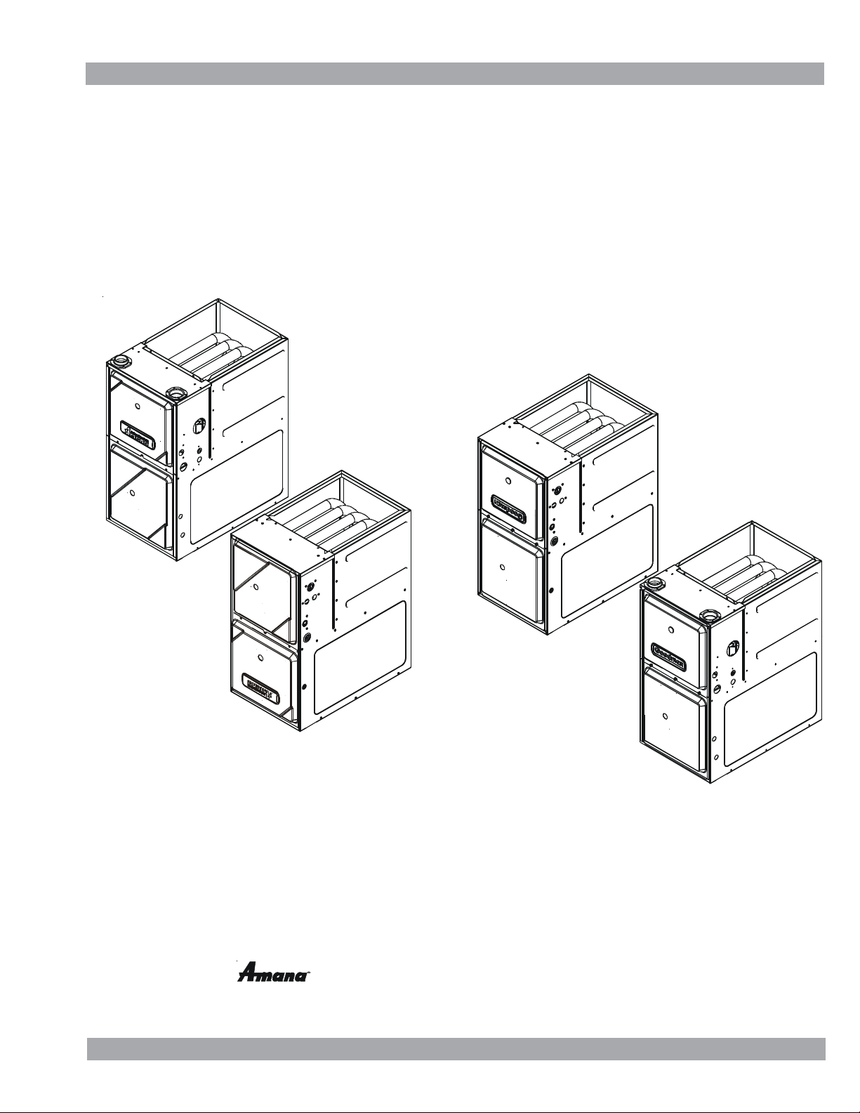
Service Instructions
GMSS9*/GCSS9*/AMSS9*/ ACSS9*
Single Stage Gas Furnaces
and Accessories
This manual is to be used by qualified, professionally trained HVAC technicians only. Goodman does not assume any
responsibility for property damage or personal injury due to improper service procedures or services performed by an
unqualified person. The material in this manual does not supercede manufacturer's installation and operation instructions.
is a registered trademark of Maytag Corporation or its related companies
and is used under license to Goodman Company, L.P., Houston, TX. All rights reserved.
Copyright © 2014 Goodman Manufacturing Company, L.P.
RS6612012
August 2014
Page 2
TABLE OF CONTENTS
IMPORTANT INFORMATION..........................2 - 6
PRODUCT IDENTIFICATION..........................7-11
INSTALLATION CONSIDERATIONS ..........12 - 30
SYSTEM OPERATION ......................................31
SERVICING TABLE OF CONTENTS ................38
TROUBLESHOOTING.................................42- 43
SERVICING ..................................................44- 54
MAINTENANCE ............................................55- 57
ACCESSORIES...........................................32- 37
IMPORTANT INFORMATION
Pride and workmanship go into every product to provide our customers with quality products. It is possible, however,
that during its lifetime a product may require service. Products should be serviced only by a qualified service
technician who is familiar with the safety procedures required in the repair and who is equipped with the proper tools,
parts, testing instruments and the appropriate service manual. REVIEW ALL SERVICE INFORMATION IN THE
APPROPRIATE SERVICE MANUAL BEFORE BEGINNING REPAIRS.
IMPORTANT NOTICES FOR CONSUMERS AND SERVICERS
RECOGNIZE SAFETY SYMBOLS, WORDS AND LABELS
WARNING
T
O PREVENT THE RISK OF PROPERTY DAMAGE, PERSONAL INJURY, OR DEATH,
DO NOT STORE COMBUSTIBLE MATER IALS OR USE GASOLINE OR OTHER
FLAMMABLE LIQUIDS OR VAPORS IN THE VICINITY OF THIS APPLIANCE.
WARNING
G
OODMAN WILL NOT BE RESPONSIBLE FOR ANY INJURY OR PROPERTY DAMAGE ARISING FROM IMPROPER SERVICE OR SERVICE PROCEDURES.
I
F YOU INSTALL OR PERFORM SERVICE ON THIS UNIT, YOU ASSUME RESPONSIBILITY FOR ANY PERSONAL INJURY OR PROPERTY DAMAGE WHICH
MAY RESULT.
M
ANY JURISDICTIONS REQUIRE A LICENSE TO INSTALL O R SERVICE HEATING AN D AIR CONDITIONING EQUIPMENT.
WARNING
HIGH VOLTAGE
D
ISCONNECT ALL POWER BEFORE SERVICING OR
INSTALLING THIS UNIT.
BE PRESENT.
DAMAGE, PERSONAL INJURY OR DEATH.
FAILURE TO DO SO MAY CAUSE PROPERTY
MULTIPLE POWER SOURCES MAY
2
Page 3
IMPORTANT INFORMATION
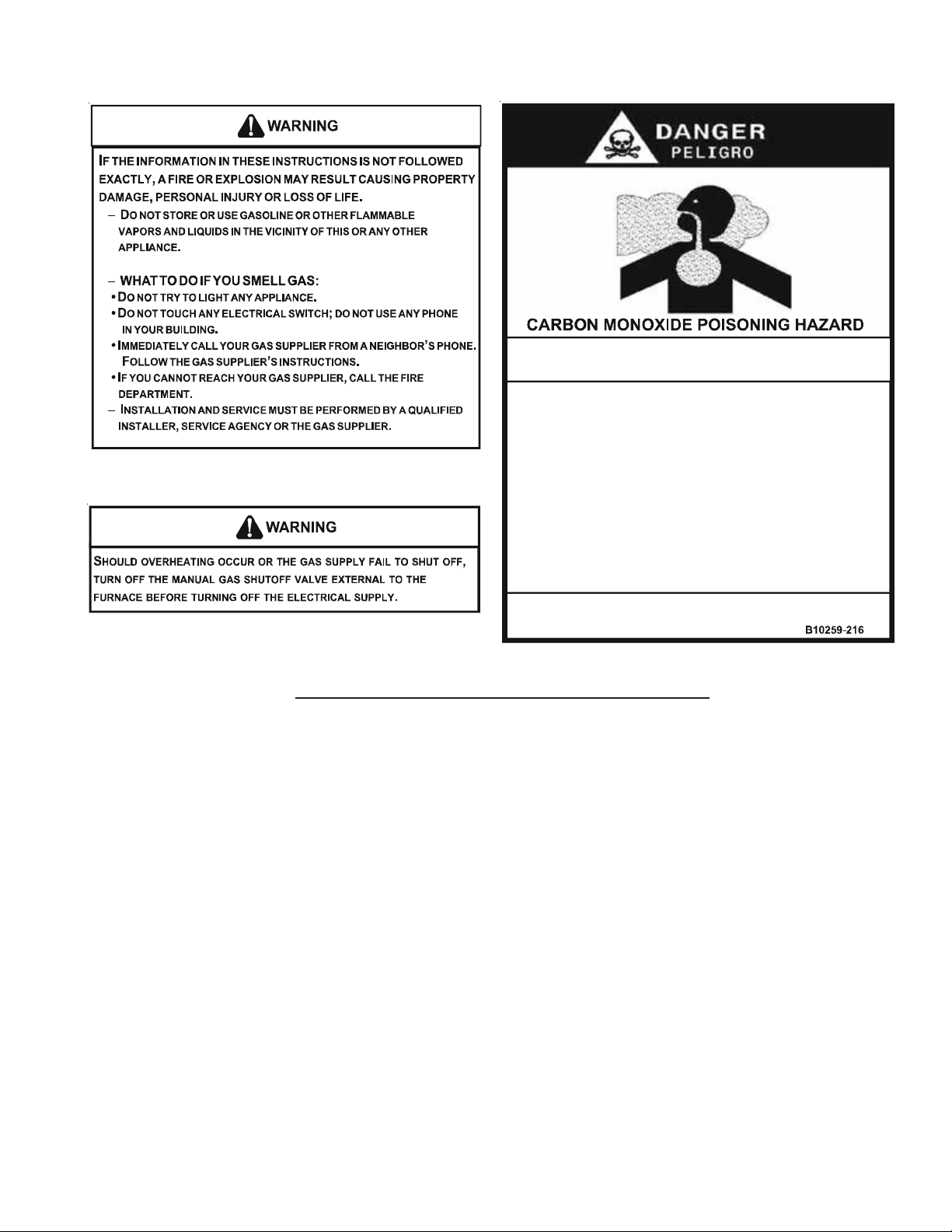
Special Warning for Installation of Furnace or Air Handling Units in
Enclosed Areas such as Garages, Utility Rooms or Parking Areas
Carbon monoxide producing devices (such as an automobile, space
heater, gas water heater, etc.) should not be opera ted in enclosed areas
such as unventilated garages, utility rooms or parking areas because of
the danger of carbon monoxide (CO) poisoning resulting from the exhaust
emissions. If a furnace or air handler is installed in an enclosed area s uch
as a garage, utility room or parking area and a carbon monoxide producing
device is operated therei n, there must be adequate, direct outside
ventilation.
This ventilation is necessary to avoid the danger of CO poisoning which
can occur if a carbon monoxide producing device continues t o operate in
the enclosed area. Carb on monoxide emissions can be (re)circu lated
throughout the structure if the furnace or air handler is operating in any
mode.
CO can cause serious illness including permanent brain damage or death.
To locate an authorized servicer, please consult your telephone book or the dealer from whom you purchased this
product. For further assistance, please contact:
CONSUMER INFORMATION LINE
GOODMAN® BRAND PRODUCTS
TOLL FREE
1-877-254-4729 (U.S. only)
email us at:
customerservice@goodmanmfg.com
fax us at: (731) 856-1821
email us at: hac.consumer.affairs@amanahvac.com
CONSUMER INFORMATION LINE
AMANA® BRAND PRODUCTS
TOLL FREE
1-877-254-4729 (U.S. only)
fax us at: (731) 856-1821
(Not a technical assistance line for dealers.)
(Not a technical assistance line for dealers.)
Outside the U.S., call 1-713-861-2500.
(Not a technical assistance line for dealers.) Your telephone company will bill you for the call.
3
Page 4
IMPORTANT INFORMATION
O
R
F
D
E
A
R
W
A
R
I
N
:
G
N
e
x
p
l
p
r
e
s
s
h
i
T
.
A
w
i
h
t
e
h
t
B
E
.
B
a
e
r
b
c
e
s
e
t
W
H
s
U
e
.
C
N
e
v
h
a
n
e
t
c
h
e
o
r
o
D
.
D
m
m
I
t
h
e
s
y
s
o
i
o
s
n
m
a
o
F
a
t
n
t
y
n
a
l
i
n
j
u
r
a
p
l
p
i
n
a
c
e
g
n
i
n
t
a
o
i
i
e
.
u
n
r
r
b
o
D
O
R
E
P
O
o
g
f
a
r
B
s
.
u
a
s
s
e
o
m
e
h
t
n
e
e
o
f
l
A
T
T
O
D
o
r
D
n
t
o
t
n
o
D
o
o
t
t
s
n
t
u
d
o
o
a
m
d
i
I
m
e
p
o
h
n
F
e
.
u
c
y
o
a
f
I
i
c
f
h
a
t
e
l
l
n
o
y
y
o
l
u
r
u
e
s
r
o
e
t
o
d
o
,
n
d
'
t
y
r
t
n
i
c
i
n
F
a
o
.
o
s
x
i
n
o
p
.
l
h
t
i
s
e
u
o
t
l
e
y
d
a
t
e
i
c
p
a
p
i
l
a
n
c
e
n
e
a
d
a
m
n
E
B
I
f
y
o
u
d
o
y
n
l
O
y
t
n
l
r
s
a
a
r
e
u
s
l
t
c
a
s
l
o
o
s
o
r
d
o
e
s
n
h
o
t
e
d
v
i
c
e
w
E
o
u
e
e
o
r
h
s
c
y
h
o
l
y
r
t
n
t
t
o
R
A
T
I
G
N
e
r
e
s
u
o
t
s
g
a
h
s
s
i
e
a
o
.
r
I
F
Y
O
U
a
i
h
t
o
l
g
t
n
a
n
c
h
y
e
l
e
a
n
y
p
h
n
o
l
l
y
c
a
l
u
y
o
l
h
t
e
o
g
l
w
n
e
o
r
t
c
h
a
m
e
a
t
r
e
d
p
o
p
a
t
u
n
s
d
h
e
t
e
l
f
I
.
v
p
o
e
a
r
t
t
i
i
r
e
e
a
o
t
m
r
t
a
p
l
p
i
n
a
c
e
l
l
i
f
u
e
a
i
a
q
l
n
o
e
r
d
t
p
a
l
g
n
a
s
c
o
t
S
O
Y
U
R
O
O
F
R
E
n
o
t
f
o
l
w
l
o
u
f
a
i
g
i
m
v
S
y
c
e
r
a
y
e
h
e
,
i
d
c
o
r
s
n
g
i
p
r
o
p
i
f
e
l
.
v
e
.
a
p
l
t
i
o
o
c
h
a
t
m
a
u
r
b
u
h
t
e
h
t
s
m
a
l
a
l
l
e
l
x
n
e
e
l
l
o
t
t
a
i
h
n
a
t
e
r
M
L
E
L
G
a
p
p
i
l
a
c
e
n
r
i
t
c
s
w
c
h
t
i
i
b
n
u
y
o
r
a
g
s
s
u
p
p
s
s
u
p
p
l
e
i
'
r
o
a
s
u
g
s
u
r
n
.
t
i
n
u
n
t
o
r
r
r
l
w
i
l
n
p
o
t
c
a
l
a
q
l
u
a
l
p
t
e
d
e
r
i
p
a
r
a
n
f
y
p
h
a
t
r
v
c
e
r
i
s
e
e
t
n
y
p
r
e
a
a
l
w
h
i
c
a
h
h
Y
T
E
F
A
R
E
P
t
h
e
e
s
e
r
t
y
e
s
i
t
I
l
y
l
i
t
c
a
n
b
e
r
y
o
r
u
n
h
t
e
f
i
a
r
n
d
A
S
.
;
u
i
d
n
l
i
g
r
e
l
i
o
r
f
s
r
i
s
t
n
e
r
p
l
p
i
h
t
e
g
n
s
h
i
u
i
d
s
f
e
i
m
a
y
s
a
b
c
h
i
n
c
h
t
o
t
f
s
b
e
e
G
A
I
N
T
n
s
i
t
u
r
t
i
c
d
d
l
u
,
e
e
e
o
a
m
a
e
g
,
u
q
i
p
p
e
d
l
i
h
g
s
t
h
a
n
.
d
h
t
e
a
p
p
l
a
i
o
o
r
i
w
l
l
.
a
n
i
h
m
e
g
b
c
i
t
o
s
.
n
o
c
r
l
s
o
t
a
n
l
o
t
r
u
n
r
b
y
v
r
i
c
e
n
i
s
u
t
e
r
l
f
a
n
u
e
n
e
w
d
r
e
i
s
i
n
p
t
n
a
o
c
o
o
r
l
t
n
n
u
e
a
n
w
d
r
E
N
M
E
n
s
c
e
n
o
'
r
s
.
r
v
e
e
e
r
i
a
e
.
t
r
c
t
e
t
.
r
A
V
E
R
T
I
S
S
E
l
a
l
e
t
t
r
r
s
i
q
u
e
e
t
n
r
a
î
n
c
o
p
r
o
r
e
C
a
t
A
.
m
u
i
n
a
u
o
t
m
d
'
a
l
l
u
B
.
A
V
A
f
n
i
e
r
n
u
e
c
e
a
t
r
e
p
u
v
E
U
Q
e
N
p
C
.
u
q
'
à
l
a
i
S
p
a
é
r
e
t
n
e
t
d
é
c
l
e
e
p
N
D
.
d
a
n
s
e
n
t
c
h
m
p
e
r
o
t
u
e
t
M
e
e
s
l
i
n
s
t
d
e
d
é
c
e
l
a
n
t
d
e
s
e
l
l
e
o
s
u
l
n
p
i
e
p
a
e
l
r
'
d
u
n
d
i
s
p
o
a
i
u
t
q
e
m
e
m
e
l
û
r
r
e
b
N
T
D
E
u
o
a
t
t
e
u
l
r
t
o
d
d
u
e
r
e
g
a
n
g
z
i
s
s
o
e
s
n
'
t
a
c
c
u
F
A
I
R
E
e
p
N
a
s
t
o
c
h
e
t
u
N
n
i
'
l
s
u
i
e
t
r
p
p
e
e
r
A
l
e
n
e
m
p
l
e
R
s
p
e
c
t
o
f
u
n
r
s
s
i
e
i
p
S
e
s
r
o
i
c
e
n
n
i
d
e
o
u
u
o
s
r
s
e
l
i
a
m
a
n
n
;
m
r
n
e
a
e
t
t
e
p
e
l
a
p
r
e
;
r
d
o
e
f
c
r
e
r
n
u
e
e
r
c
h
n
a
s
s
e
s
e
v
r
'
l
e
a
c
u
o
,
m
e
c
i
n
q
i
u
l
a
a
l
o
t
u
r
t
c
e
c
o
m
n
d
m
a
Q
E
T
N
:
u
r
t
i
c
o
s
n
d
c
h
e
r
u
n
n
i
d
a
m
m
a
g
e
a
p
e
r
t
e
d
e
c
o
o
t
m
p
r
i
d
t
f
s
'
i
a
l
l
u
m
e
b
l
û
r
l
t
e
n
e
u
l
m
r
a
n
u
L
E
F
A
I
R
o
u
p
a
e
l
d
'
r
n
e
i
R
a
z
l
f
.
e
p
u
n
t
l
s
l
o
u
m
u
a
e
r
l
u
n
S
'
Y
I
L
n
d
e
e
t
r
'
a
l
l
u
e
r
u
a
c
u
n
é
é
t
l
u
a
c
u
n
m
m
é
i
i
d
a
e
t
é
t
l
o
y
e
a
t
n
l
à
l
e
r
r
a
t
t
e
u
z
g
a
d
r
e
n
é
r
n
e
n
p
e
s
.
o
l
t
u
e
n
r
r
e
e
j
a
i
m
a
s
e
e
s
e
i
t
c
o
n
c
é
c
u
e
r
n
t
n
h
e
m
a
t
l
n
t
a
e
e
x
p
o
l
s
i
o
n
i
r
a
p
d
t
e
c
e
m
e
p
è
e
n
l
t
i
f
é
i
p
o
n
u
i
r
u
s
e
d
i
a
t
p
r
o
n
u
i
e
q
é
t
E
D
A
R
E
C
H
u
i
o
c
q
n
e
u
a
s
n
l
e
p
é
r
c
e
n
d
i
e
o
u
m
s
a
t
r
é
i
e
l
h
u
e
e
A
i
l
.
l
m
t
m
v
s
i
e
d
p
s
e
i
a
v
e
l
l
a
l
l
u
i
a
e
q
g
u
r
e
N
.
p
a
t
s
l
e
l
m
e
n
.
t
E
F
N
C
O
a
i
p
r
l
p
e
o
r
u
d
s
p
u
è
r
r
p
d
r
s
q
u
e
r
l
a
i
'
i
v
e
u
d
a
u
s
o
N
U
E
O
m
l
e
r
'
p
a
p
a
n
p
m
é
e
o
e
e
i
c
o
o
p
o
s
y
t
r
e
u
e
t
t
u
r
p
r
r
o
h
a
n
e
d
s
n
o
f
u
l
r
e
e
t
n
h
n
e
p
o
d
ú
n
l
e
u
s
i
s
r
c
t
n
n
a
d
p
e
,
p
l
e
e
d
v
i
'
r
a
d
m
'
p
d
o
l
e
u
o
r
,
p
n
a
e
e
s
t
i
n
q
e
u
l
a
i
i
f
é
d
e
l
u
e
r
a
i
u
n
n
c
u
e
n
e
r
l
s
i
a
'
i
l
a
u
e
n
p
i
a
t
r
l
p
r
'
p
e
e
a
c
t
s
è
t
m
d
e
c
e
l
é
p
o
g
n
é
s
R
E
T
T
E
M
L
I
R
E
n
e
e
r
p
s
e
c
t
e
p
a
s
e
s
n
t
m
a
n
n
u
e
e
p
x
s
,
d
e
s
é
l
n
a
i
s
e
.
e
s
l
I
e
s
e
u
.
u
m
e
r
n
e
e
t
T
I
N
N
O
d
é
c
l
e
e
r
l
n
a
c
h
e
c
a
,
r
e
t
l
.
D
E
U
R
i
l
e
l
é
e
c
q
i
u
r
e
t
e
m
â
i
e
b
t
l
n
s
s
i
e
d
u
r
e
v
n
o
s
i
.
i
i
n
t
o
s
d
u
e
c
v
r
i
s
l
e
r
i
d
s
o
u
s
i
n
à
i
t
l
e
f
f
t
c
e
d
e
a
t
e
r
l
n
u
c
Q
i
o
.
n
q
p
u
p
e
r
a
e
r
i
d
e
.
é
t
l
n
é
p
o
g
p
e
e
e
p
A
l
.
p
a
e
r
t
l
e
i
o
ô
n
e
r
l
t
t
e
'
l
e
a
u
a
s
d
n
á
u
e
l
s
l
o
o
i
n
o
s
i
n
s
t
E
R
,
r
E
D
A
Z
G
;
n
.
t
g
z
a
d
e
e
s
g
a
z
.
e
t
u
e
t
é
r
n
u
.
T
A
V
N
R
A
I
L
P
e
R
S
T
P
O
!
.
1
h
t
i
e
S
.
2
T
u
.
3
T
h
.
4
d
e
o
D
u
P
.
5
o
D
.
6
W
a
s
m
e
h
t
i
n
o
n
g
a
u
P
.
7
o
t
e
R
.
8
u
T
.
9
p
o
1
e
S
.
0
t
f
I
1
.
1
o
f
l
O
f
s
e
1
.
S
e
2
.
T
u
s
i
f
3
.
P
u
D
o
4
.
R
e
a
a
s
l
b
e
.
l
h
t
e
t
e
m
h
r
t
l
a
l
p
n
r
o
f
f
i
a
i
s
a
p
l
p
n
c
v
c
h
c
e
w
h
i
i
o
y
r
t
n
t
o
t
s
h
h
t
e
g
s
a
c
r
e
o
.
n
f
o
t
i
f
)
i
v
5
t
e
(
a
s
o
g
e
l
f
r
l
n
s
m
e
l
g
l
a
h
t
e
s
t
a
e
f
y
.
i
h
s
l
b
t
a
e
l
o
n
t
e
g
s
o
,
s
h
g
a
c
s
o
n
"
N
O
.
"
p
l
a
c
e
a
c
c
e
n
r
o
l
n
a
l
e
l
o
t
w
e
r
h
t
e
h
t
e
m
r
t
o
s
t
a
n
i
a
p
l
h
p
e
h
t
e
i
s
l
w
n
o
s
a
G
f
o
T
A
v
c
e
r
i
n
c
h
e
t
O
U
T
T
t
t
h
e
t
h
e
r
r
n
o
f
f
a
l
l
i
s
e
v
r
c
i
e
s
h
t
h
e
g
a
o
n
f
t
o
c
r
p
l
a
c
e
c
o
G
I
T
N
S
s
h
a
e
d
o
o
e
a
l
i
m
,
s
i
i
f
x
t
s
e
a
a
c
r
t
p
i
c
R
m
e
t
s
e
n
y
t
s
e
w
i
u
g
h
c
o
i
n
n
i
,
n
f
y
o
t
s
o
r
s
c
t
p
p
t
t
e
u
p
i
a
N
o
l
e
o
i
e
f
t
n
o
f
m
r
o
s
t
l
a
t
t
r
s
e
o
t
m
t
t
n
r
t
t
u
c
u
l
S
T
o
m
r
u
e
t
e
l
l
p
a
c
i
r
i
l
a
o
d
i
w
l
o
c
i
t
a
i
n
l
n
s
c
t
b
e
c
o
s
o
t
e
w
e
t
a
p
i
t
e
n
a
p
l
h
o
t
u
q
a
h
e
l
o
e
s
i
d
O
a
o
d
p
.
v
n
n
e
n
l
n
c
r
o
O
t
a
i
c
r
p
n
t
h
t
p
i
t
l
t
n
P
t
n
e
e
c
s
o
s
e
g
F
t
e
r
i
p
d
w
e
i
l
c
a
l
i
s
y
l
g
t
h
u
n
b
r
e
b
h
y
r
o
v
t
e
e
r
O
"
o
o
e
r
u
c
l
a
h
t
a
e
n
e
r
g
F
"
o
!
l
l
w
o
i
a
o
b
n
o
v
e
'
s
m
e
l
t
l
r
l
.
e
.
i
d
s
i
t
e
r
e
t
n
g
o
p
e
t
t
e
,
a
r
T
"
o
n
r
T
u
a
n
"
d
l
c
a
l
y
a
m
p
s
c
o
a
S
G
A
F
t
o
l
o
w
e
s
t
p
o
w
r
e
t
o
r
f
m
o
r
d
e
.
o
l
e
v
l
e
r
t
o
.
t
o
r
a
l
c
e
c
s
s
p
a
n
e
I
C
T
O
R
U
o
a
i
t
i
g
t
n
.
c
e
a
n
i
h
e
t
a
n
F
F
"
n
a
t
l
o
f
o
B
"
G
N
I
A
R
D
.
o
u
r
n
y
.
T
s
e
t
t
h
e
"
O
.
l
N
S
.
1
A
R
o
n
a
n
b
v
e
o
.
.
g
i
i
n
n
t
o
.
n
r
b
r
e
u
d
.
o
P
o
i
n
t
s
.
i
h
y
e
T
g
s
.
a
n
f
I
.
r
y
o
u
A
S
T
E
L
R
V
I
E
E
U
G
A
Z
O
P
P
A
t
i
n
g
.
a
p
p
i
l
a
P
F
F
"
R
O
B
N
I
M
A
E
N
U
M
/
N
"
O
A
M
E
V
L
N
I
O
N
A
C
I
L
E
n
c
e
o
s
i
o
i
t
n
.
Z
A
G
T
A
E
S
O
P
E
,
N
L
A
H
R
E
"
C
S
A
G
A
N
L
U
H
O
E
R
S
W
N
P
O
T
I
O
I
S
R
o
p
a
l
é
R
g
l
.
2
e
.
o
C
u
p
.
3
e
C
a
.
4
t
d
'
a
l
l
u
a
l
u
l
m
u
o
s
P
.
5
p
o
s
i
i
t
e
t
t
n
A
.
6
g
a
R
z
.
p
a
l
n
c
A
R
R
a
s
l
u
r
n
'
'
l
S
i
u
o
s
P
.
7
p
o
s
i
i
t
e
m
e
R
.
8
M
e
r
t
t
.
9
g
l
é
R
1
.
e
0
l
a
'
p
i
S
1
.
1
n
u
i
s
r
t
d
a
e
g
q
u
a
i
l
f
N
N
1
R
.
é
g
2
C
.
o
u
f
a
u
t
3
P
.
o
u
p
o
i
s
N
e
p
4
R
.
e
m
M
E
T
L
Ê
!
R
o
n
p
i
s
u
é
t
r
r
l
r
e
t
e
m
h
r
l
r
e
'
a
i
l
m
e
n
p
p
a
e
r
m
i
é
l
m
a
g
u
e
a
t
o
e
b
l
û
r
e
l
r
e
s
e
l
e
e
l
v
i
r
e
o
n
.
d
e
r
n
c
i
q
(
5
o
e
t
u
e
i
l
r
n
f
d
p
e
o
r
,
h
r
u
P
E
T
E
R
!
o
i
n
o
t
r
s
u
p
y
a
p
a
o
s
d
'
s
e
e
e
l
v
l
i
r
e
o
n
.
e
e
r
t
n
t
p
l
a
e
l
a
a
'
p
e
p
r
i
h
t
e
l
m
r
r
e
e
l
p
r
i
a
e
s
n
c
i
n
t
o
s
i
t
n
i
t
z
d
e
l
'
a
p
p
e
i
o
e
f
u
u
l
é
o
O
P
U
R
D
E
l
e
r
l
e
t
h
e
r
p
r
e
'
l
l
i
a
m
p
r
o
c
é
d
e
r
s
s
e
l
e
v
l
e
t
i
o
n
.
a
s
f
r
o
c
e
r
e
t
t
r
e
e
n
N
E
M
E
I
S
i
s
e
z
l
e
s
e
d
e
e
r
i
u
o
s
a
à
l
t
t
a
t
i
t
o
n
é
l
g
n
a
e
é
r
i
u
t
q
e
a
m
u
m
a
u
r
n
d
u
c
o
n
m
i
u
e
)
n
t
a
t
u
o
t
u
é
c
u
l
r
e
e
a
s
s
e
à
r
p
é
e
i
r
u
e
r
u
d
d
e
e
r
d
u
c
o
n
e
p
c
e
l
a
l
s
o
u
e
s
t
o
s
t
a
à
l
t
e
m
e
p
t
u
l
e
é
s
.
C
a
t
e
l
e
r
i
i
n
s
u
r
r
s
e
C
O
U
P
D
Z
G
A
m
o
t
s
a
t
e
n
a
t
t
i
o
n
à
d
e
s
e
r
i
d
u
c
R
C
A
H
E
i
n
s
u
r
o
t
c
i
t
e
s
n
s
d
é
c
u
i
r
é
t
s
u
c
e
t
i
u
e
t
q
e
t
e
t
m
e
a
t
e
c
i
r
t
q
a
t
d
n
t
pas
n
e
,
l
e
l
m
e
ô
e
d
r
l
t
s
p
o
u
r
l
d
'
e
a
e
o
n
d
a
p
'
t
l
é
c
e
d
a
g
z
,
ô
e
d
r
l
t
n
n
e
a
o
s
i
n
n
e
a
t
m
n
a
e
s
m
m
o
l
p
e
e
p
d
e
r
R
E
E
L
à
l
a
é
l
e
c
o
p
é
r
a
o
n
t
r
ô
.
é
t
l
p
u
e
t
é
r
a
r
a
u
e
l
d
'
e
a
p
p
é
d
u
n
t
'
s
o
y
e
s
s
a
y
e
e
n
.
t
u
g
a
z
à
O
"
a
l
i
s
r
s
e
r
e
c
p
p
a
y
e
r
l
i
,
a
z
e
g
d
u
e
r
n
i
s
d
s
e
e
B
q
e
e
t
é
i
u
t
t
e
p
a
s
s
e
r
'
à
l
é
u
g
a
z
à
O
"
d
'
u
a
c
c
é
s
.
.
d
e
u
e
t
r
é
a
p
r
m
a
c
r
h
,
s
e
e
t
c
n
o
u
l
p
e
u
r
n
t
e
c
h
n
i
a
g
z
.
'
L
D
M
A
R
P
'
A
P
A
e
t
m
p
r
é
a
t
u
t
i
r
q
u
e
e
d
t
o
n
i
s
d
e
'
n
e
l
d
u
g
a
z
r
p
l
u
s
b
s
s
a
e
e
r
l
i
a
.
s
è
t
m
e
à
r
F
F
/
A
R
R
E
T
"
e
l
u
h
a
c
o
m
.
S
u
r
t
e
t
t
a
t
N
s
r
i
u
y
i
'
l
a
r
e
i
c
S
I
E
r
e
l
a
'
t
r
à
o
t
t
p
p
r
e
p
i
r
s
è
r
s
d
p
u
e
i
l
c
'
s
c
t
e
a
s
c
i
t
o
.
p
e
s
/
M
A
é
.
e
l
e
r
d
m
n
I
S
I
L
l
a
p
p
e
t
i
e
O
"
,
n
s
s
d
é
i
e
c
t
é
u
i
r
u
v
a
i
n
é
t
.
R
C
H
E
"
s
e
s
s
i
i
n
o
O
N
p
l
u
s
b
a
s
s
e
a
e
r
n
.
F
F
.
l
i
i
'
l
s
/
A
R
R
E
T
"
.
l
a
p
e
c
l
e
p
a
n
n
e
a
u
d
'
a
c
c
è
s
.
2
7
1
2
0
7
1
1
N
I
T
R
E
A
O
4
Page 5
IMPORTANT INFORMATION
FOR YOUR SAFETY
READ BEFORE OPERATING
If you do not follow these instructions
WARNING:
explosion may result causing propertyexactly, a fire or
damage, personal injury or
loss of life.
A. This appliance does not have a pilot. It is equipped
with a n ignition device which au t o matically lights
to light the burner by hand.
th e burner. Do no t try
B. smell all aroun d the appliance
BEFORE OPERATING
area for gas. Be sure to smell next to the floor
bec ause some gas is heavier than air and will
settle on the floor.
WHAT TO DO IF YOU SMELL GAS
Do not tr y to light any appliance.
Do not touch any electric switch;
do not use any phone in your building.
Immediately call your gas supplier from a neighbor's
phone. Follow the gas supplier's instructions.
If you cannot re ach your gas supplier,
call the fire department.
C. Use only your hand to push in or turn the gas control lever.
Never use tools. If the lever will not push in or turn by
hand, don't try to repair it, call a q ualified service
technician. Forc e or attempted repair may result in a fire
or explosion.
D.
Do not use this appliance if any part has been underwater.
Immediately ca ll a qu a l ified service technician to inspect
th e appliance and to rep lace any part of the control
system and any ga s control which has been underwater.
LIRE AVANT DE METTRE
EN MARCHE LIRE
AVERTISSEMENT:
la lettre les instructions dans le presén t manuel
risque de déclencher un incendie ou une exp losion
entraînant des dommages matériels, des lesions
corporelles ou la perte de vies humaines.
Cet appareil ne comp orte pas de veilleuse. Il est
A.
muni d'un dispositif d'allumage qui allume
automatiquemen t le brûleur. Ne pas tenter
d'allumer le brûleur manuellement.
B. AVANT DE LE FAIRE FONCTIONNER,
renifler tout autour de l'ap pariel pour decéler
une odeur de gaz. Renifler prés du plancher, car
certains gaz son t plus lourds que l'air et
peuv en t s'accumuler au niveau du sol.
QUE FAIRE S'IL Y A UNE ODEUR DE GAZ
Ne pas tenter d'allumer d'appareils.
Ne
toucher à au c un interrupteur; ne pas vous servir
des téléphone s dans le bâtiment.
Appelez immédiatement votre fo urnisseur de gaz depuis
un voisin. Suivez les instructions du fournisseur de gaz
Si vous ne pouvez rejoindre le fournisseur de gaz,
appelez le service des incendies.»
C. Ne pousser ou tourner la ma nette d'admission du gaz
qu'à la main. Ne jamais emploer d'outil à cette fin.
Si la manette reste coincée, ne tenter pas de la
réparer; appel e z un technicien qualifié. Quiconque
te nte de forcer la m anette ou de la réparer peut
provoquer un e explosion ou un incendie.»
D. Ne pas se servir de cet appareil s'il a été plongé dans
l'eau, même partiellement. Fa ir e inspecter l'appareil
par un technici en qualifié et remplacer toutr partie du
systéme de contrôle et toute commande qui ont été
plongées dans l'eau.»
Quiconque ne re specte pas à
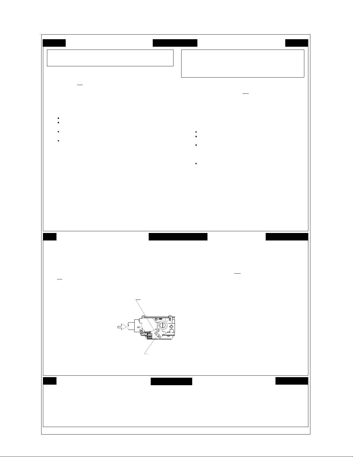
OPERATING INSTRUCTIONS
1. Re ad the safety inform ation abov e on
STOP.
th i s label.
2. Set the thermostat to lowest se tting.
3. Turn of f all electric power to the appliance.
4. This appliance is eq uipped with an ignition
device which automatically lights the burner.
Do not try to light the burner by hand.
5. Push the gas control leve r to Position.
Do not force.
6. Wait five (5) minute s to clear out any gas. Then
sme ll for gas, including near the floor. If you
th en smell gas, Follow
in the safety information above
on this label if you don 't smell
gas, go to ne xt step.
7. Push gas control lever
to
"ON".
8. Replace access panel.
9. Turn on all electric
power to the appliance.
10. Set thermostat to desired setting.
11. If the appliance wil l not operate,
follow the instructions “To Turn
Off Gas To Applianc e " and call your
servi c e tec hnician or gas company.
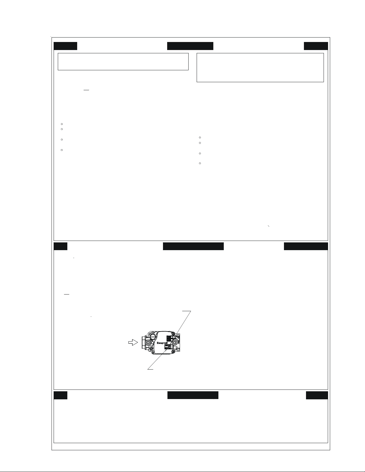
STOP. "B"
"OFF”
GAS
INLE T
ARRIVEE
DU GAZ
ROBINET A GAZ
MANUEL, EN POS
"ON/MARCHE"
MANUAL GAS
LEVER SHOWN
IN "ON" POS
TO TURN OFF GAS TO APPLIANCE
1. Set the thermostat to lowest setting.
2. Turn off all electric power to the appliance
if service is to be performed.
3. Push the gas control l ever to Position.
Do not force.
4. Replace control access panel.
"O FF”
MISE EN MARCHE
1. Lisez les instructions de sécurité dans la
ARRÊTEZ
section supérieure de cette étiquette.
.
2. Régler le thermostat à la température la plus basse.
3. Couper l'alimentation électrique de l'appareil.
4. Cet appareil me n ager etant dote d'un systeme
d'allumage au t om atiqu e , ne pas essayer à
allumer le brûleur manuellement.
5. Po usse le levier du contrÔle du gaz a
position.
6. Attendre cinq (5) minutes pour laisser echapper tout le
gaz. Renifler tout autour de l'appareil, y compris prés du
plancher, pour déceler une odeur de gaz. Si c ' est le ca s,
Passer à l'etape B des instructions de securite
ARRÊTEZ.
sur la portion su perieure de cette etiquette.
S'il n'y a pas d'odeur de ga z , passer à l'etàpe suivante.
7. P o u sse l e le v i e r du contrôle du gaz à
position.
8. Remettre en place le pann eau d'accés.
9. Mettre l'appareil sous tension.
10. Régler le thermostat à la température désirée.
11. Si l'appareil ne se met pas en marche, suivre les
instructions intitulées Comment couper l' ad mi ssion
de gaz de l'appareil et appeler un technicien
qualifié ou le fo urnisseur de gaz.
"OFF/ ARRET”
"ON/MARCHE”
POUR COUPER L'ADMISSION
DE GAZ DE L'APPAREIL
1. Régler le thermostat à la température la plus bassé.
2. Couper l'alimentation él ectrique de l'appareil s'il
faut procéder à des operations d'entretien.
3. Pousse le levier du contrôle du gaz à
position.
Ne pas forcer.
4. Remettre en place le panneau d'accés.
"OFF/ ARRET"
0140F00681 R EV A
5
Page 6
IMPORTANT INFORMATION
FOR YOUR SAFETY READ BEFORE OPERATING
If you do not follow these instructions exactly,
a fire or explosion may result causing property
damage, personal injury or loss of life.
A. This appliance does not have a pilot. It
is equipped with an ignition device which
automatically lights the burners. Do n
try to light the burners by hand.
B. BEFORE OPERATING smell around
the appliance area for gas. Be sure to
smell next to the floor because some gas
is heavier than air and will settle on the
floor.
WHAT TO DO IF YOU SMELL GAS
Do not try to light any appliance.
Do not touch any electric switch;
do not use any telephone in your
building.
Immediately call your supplier
from a neighbor's phone. Follow
the gas suppliers instructions.
ot
If you cannot reach your gas supplier,
call the fire department.
C. Use only your hand to move the gas
control switch or knob. Never use
tools. If the gas control switch or knob
will not operate, don't try to repair it,
call a qualified service technician.
Force or attempted repair may result in
a fire or explosion.
D. Do not use this appliance if any part
has been under water. Immediately call
a qualified service technician to inspect
the appliance and to replace any part of
the control system and any gas control
which has been under water.
OPERATING INSTRUCTIONS
1. STOP! R e ad the safety information
above on this label.
2. Set the thermostat to lowest setting.
3. Turn off all electric power to the
appliance.
4. This appliance is equipped with an
automatic ignition system which
automatically lights the burne rs. Do n
try to light the burners by hand.
5. Remove con trol access panel.
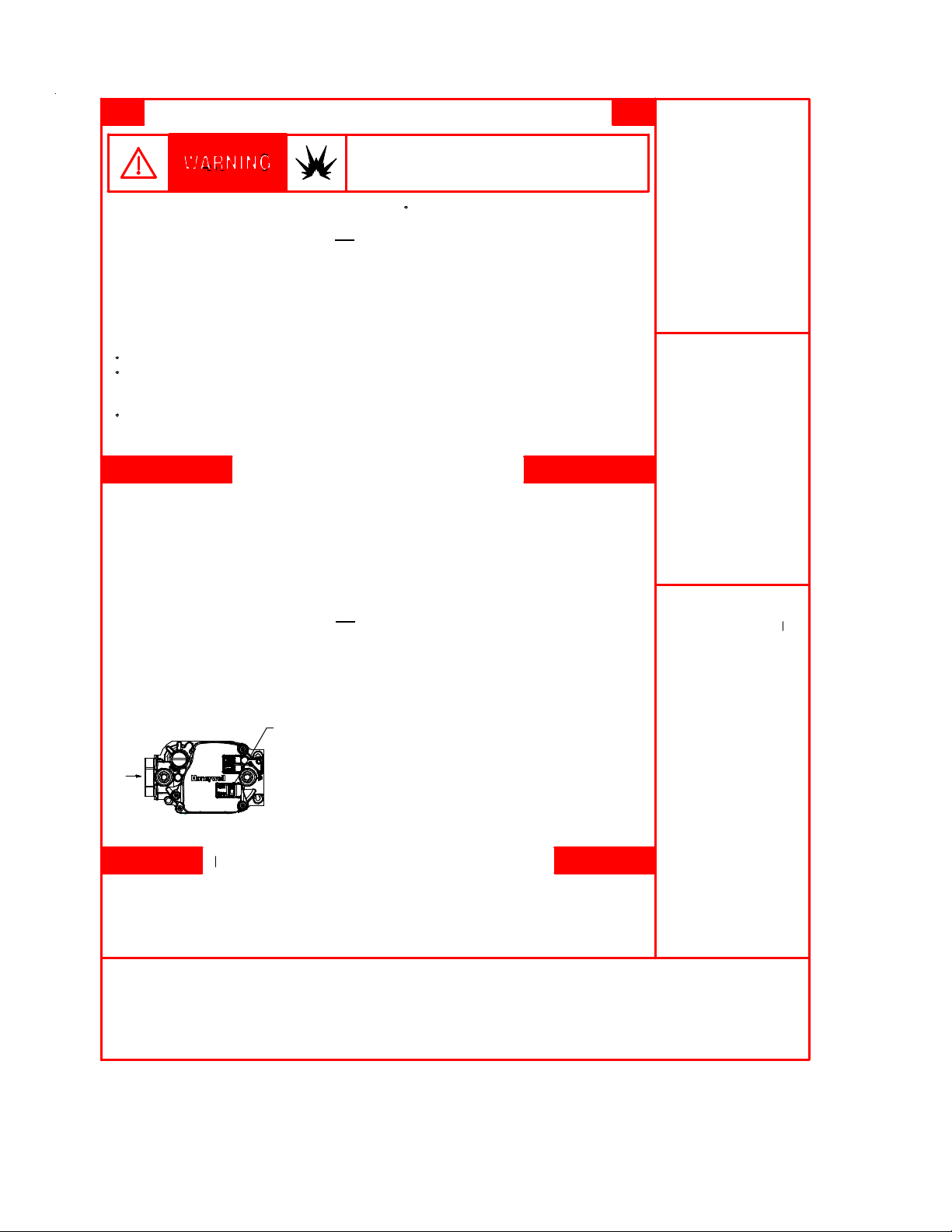
6. Move the gas control switch or knob
to "OFF".
GAS CONTROL
SWIT C H SHO W N
IN "ON" POSIT ION
ot
7. Wait five (5) minutes to clear out any
gas. If you then smell gas, STOP!
Follow "B" in the safety information
above on this label. If you don't smell
gas, go to the next step.
8. Move the gas control switch or knob
to "ON".
9. Replace control access panel.
10. Turn on all electric power to the
appliance.
11. Set the thermostat to the desired
setting.
12. If the appliance will not operate,
follow the instructions "To Turn Off Gas
To Appliance" and call your service
technician or gas supplier.
TO TURN OFF GAS TO APPLIANCE
1. Set the thermostat to its lowest setting.
2. Turn off all electric power to the
appliance if service is to be performed.
3. Remove control access panel.
4. Move the gas control switch or knob
to "OFF". Do not force.
5. Replace control access panel.
WARNING:
installation, adjustme nt,
alteration, service or
maintenance can
cause injury or
property damage.
Refer to the user's
information manual
provided with this
furnace. For assistance
or additional information
consult a qualified
installer, servi ce ag ency
or the gas supplier.
This furnace must be
installed in accordance
with the manufacturers
instructions and local
codes. In the absence
of local codes, follow
the National Fuel Gas
Code, ANSI Z223.1.
WARNING:
installed, operated
and maintained in
accordance with the
manufacturer's
instructions, this
product could expose
you to substances
in fuel combustion
which can cause
death or serious
illness and which
are known to the
State of California to
cause cancer, birth
defects or other
reproductive harm.
This product contains
fiberglass insulation.
Fiberglass insulation
contains a chemical
known by the State of
California to cause
cancer.
Improper
If not
FOR YOUR SAFETY
Do not store or use gasoline or
other flammable vapors and liquids in the vicinity of this
or any other appliance.
6
0140F00688 Rev A
Page 7

PRODUCT IDENTIFICATION
The model and manufacturing number are used for positive identification of component parts used in manufacturing.
Please use these numbers when requesting service or parts information.
* M S S 96 060 3 B N A A
1 2 3 4 5 6 7 8 9 10 11 12 13 14
Brand Minor Revision
A- Amana® G- Goodman® A - Initia l Releas e
Configuration
M - U pflow/Horizontal Ma jor Revision
C - Downflow/Horizontal A - Initia l Releas e
K - Dedicated Upflow B - 1 st Revision
D - Dedicated Downflow
Airflow N - Natur a l Gas
C - Variable Speed/ComfortNet X - Low Nox
E - High Efficiency
S - Single Speed Cabinet W idth
Gas Valve S tages B - 17.5"
M - Modulating C - 21"
V - 2 Stage D - 24.5"
H - Convertible 2 Stage
S - Single Stage Maximum CFM
AFUE 4 - 1600 CFM
97 - 97% AFUE 5 - 2000 CFM
80 - 80% AFUE
B - 1 st Revision
Nox
A - 14"
3 - 1200 CFM
MBTU/h
040 - 40,00 0
060 - 60,00 0
080 - 80,00 0
100 - 100,000
120 - 120,000
7
Page 8
PRODUCT IDENTIFICATION
MODEL # MFG # DESCRIPTION
GMSS920402BNAA
GMSS92
GMSS920603BNAA
GMSS920803BNAA
GMSS920804CNAA
GMSS920805CNAA
GMSS921004CNAA
GMSS921005CNAA
GMSS921205DNAA
Goodman® Brand 92% Single Stage Gas Furnace.
Installation, 1- stage gas valve induced draft. PSC motor . 120- volt silicon carbide
17-second hot sur fac e ignit ion. Left or r ight gas pipe ent r y. The furnace also
feat ures an aluminized steel tubular heat exchanger. A vailable cabinet widt hs
are 17.5", 21", and 24.5 " wide .
34.5" tall, Upf low/ Horizontal
GCS S 9 2
GMSS96
GCS S 9 6
GCSS9204 02BNAA
GCSS9206 03BNAA
GCSS920804CNAA
GCSS921005CNAA
GMSS960402BNAA
GMSS960603BNAA
GMSS960803BNAA
GMSS960804CNAA
GMSS960805CNAA
GMSS961005CNAA
GMSS961205DNAA
GCSS9604 02BNAA
GCSS9606 03BNAA
GCSS960804CNAA
GCSS 961005CNAA
GCSS961205DNAA
Goodman® Brand 92% Single Stage Gas Furnace.
Downflow/Horizontal Installation, 1-stage gas valve induced draft. PSC motor.
120-volt silicon carbide 17-second hot sur f ac e ignit ion. Lef t or right gas pipe
entry. T he furnace also features an aluminized steel t ubular heat exchanger.
Available cabinet widths are 17.5" and 21" wide.
Goodman® Brand 96% Single Stage Gas Furnace.
Inst allation,1-st age ga s v al ve induced dr af t. PSC mot or . 120 volt silic on c ar bid e
17-second hot sur fac e ignit ion. Left or r ight gas pipe ent r y. The furnace also
feat ures an aluminized steel tubular heat exchanger. A vailable cabinet widt hs
are 17.5" 21" and 24.5" wide.
Goodman® Brand 96% Single Stage Gas Furnace.
Downflow/Horizontal Installation, 1-stage gas valve induced draf t. PSC motor.
120-volt silicon carbide 17-second hot sur f ac e ignit ion. Lef t or right gas pipe
entry. T he furnace also features an aluminized st eel t ubular heat exchanger.
Available cabinet widths are 17.5" , 21", and 24. 5" wide.
34.5" tall,
34.5" tall, Upf low/ Horizontal
34.5" tall,
8
Page 9
PRODUCT IDENTIFICATION
MODEL # MFG # DESCRIPTION
AMSS920402BNAA
AMSS92
AMSS920603BNAA
AMSS920803BNAA
AMSS920804CNAA
AMS S 92 0805 CN AA
AMS S 92 1004 CN AA
AMSS921005CNAA
AMSS921205DNAA
®
Ama na
34.5 " tall, 1 - st age gas valv e in duced draft. PSC mot or. 1 20- volt silicon c arbide 17second hot surface ignit ion. Left or right ga s pipe entry . The f urnace also f ea tures
a stainless steel tubular he at exc h ange r . Available c abi ne t widt h s are 17.5", 21",
and 24. 5" wid e.
Brand 92% Single Stage Gas Furnace.
Upflow/Horiz ontal Installation,
ACSS92
AMSS96
ACSS96
ACSS920402BNAA
ACSS920603BNAA
ACSS920804CNAA
ACSS921005CNAA
AMSS960402BNAA
AMSS960603BNAA
AMSS960803BNAA
AMSS960804CNAA
AMS S 96 0805 CN AA
AMSS961005CNAA
AMSS961205DNAA
ACSS960402BNAA
ACSS960603BNAA
ACSS960804CNAA
ACSS961005CNAA
ACSS961205DNAA
®
Ama na
34.5 " tall, 1 - st age gas valv e in duced draft. PSC mot or. 1 20- volt silicon c arbide 17second hot surface ignit ion. Left or right ga s pipe entry .The f ur n ac e al so fe atures
a stainless steel tubular he at exc h ange r . Available c abi ne t widt h s are 17 .5" and
21" wi de .
Ama na
34.5 " tall, 1 - st age gas valv e in duced draft. PSC mot or. 1 20- volt silicon c arbide 17second hot surface ignit ion. Left or right ga s pipe entry . The f urnace also f ea tures
a stainless steel tubular he at exc h ange r . Available c abi ne t widt h s are 17 .5" 21"
& 24.5 wide.
Ama na
Inst allation, 34.5" tall, 1-stage gas valve induced dra ft. PSC motor . 120- volt
silicon car bi de 17 - secon d ho t surface ignit io n. Left or right gas pipe e ntry . The
furnace also featur es a stainless st eel t ubular heat exchanger. Available cabinet
widths are 17.5", 21", and 24. 5" wide.
Brand 92% Single Stage Gas Furnace
®
Brand 96% Single Stage Gas Furnace
®
Brand 96% Single Stage Gas Furnace
. Downflow/Horiz ontal Installation,
. Upflow/Horiz ontal Installation,
. Downflow/Horizontal
9
Page 10
PRODUCT IDENTIFICATION
MODEL # MFG # DESCRIPTION
AFE18-60A
AMU1 620
AMU1 625
AMU2 020
AMU2 025
GMU1620
GMU1625
GMU2020
GMU2025
ASAS-10
ASAS-11
ASAS-12
ASAS-18
CFSB17
CFSB21
CFSB24
N/A
P1251305F
P1251306F
P1251307F
P1251308F
N/A
P1251301F
P1251302F
P1251303F
P1251304F
N/A
Fossil Fuel Kit.
located above/downstr eam of a g as or f o ssil fuel furnac e whe n used wit h a heat pump.
It will operate w ith single and two stage heat pumps and single and two st a ge
furnaces. The AFE18-60A contr ol wi ll turn the heat pump unit off wh en the furnac e is
turned on. An anti-short c ycle f ea ture initiates a 3 minute timed off delay when the
compressor goes off .
Me dia Air Clea ner.
pollen and other mic roscopic par ticles from the air passing through it. Flexible
performance rang e up to 2,000 CFM capacit y. T h e a ir c lea ner should be installed in the
system so that all the sy ste m air is circ u lated through the air cleaner . T he air c le aner
will only remove the airborne contaminants delivered t o i t. Maximum perf ormance is
obtai ned w hen the system blower is set f or continu ous operation. Carbon filters
(optional) ar e available.
Electronic Air Cleaner.
remove air c on taminants down to .01 micr on s. Car bon filt er s (optional) remov e o dor s.
Dual indicator lights show unit operation at a glance. E le c tronic proving switch c ycles
the a ir cleaner On/Off with the system fan. Durable pow der - coat paint finish resists
corrosion.
Counterflow Subbase Kit
are available for t he following furnac e widt h s: 17. 5 " wide ( CF S B 17) , 21" wide (CF S B21 )
and 24. 5" wide (CFS B 2 4) . The kits must be used t o prevent excessive temperat ur e
from reaching c ombustible mater ials, if the fu r nace is installed on a combustible floor.
This subbase effectively separa ted the fu r nace base and plenum from combustible
materials. To ensur e safe install ation, do not inst all the counter flow floor base direc tly
on car peting, t ile, or other combustible material other than wood flooring.
The AFE 18 - 60A control is d esigned f or use where t he indo or c oi l is
A high eff ic i enc y air filt r ation devi c e designed t o remove dir t, dust,
The Hi gh- Efficiency Elect r oni c Air Cleaner is designed to
. For use with 34.5" down flow furnac e models. These kits
10
Page 11

PRODUCT IDENTIFICATION
MODEL # MFG # DESCRIPTION
DCVK-20
(CVENT-2)
DCVK-30
(CVENT-3)
N/A
Concentric Vent Kit
to be "concentrically" vented through a w all or r oof. Th is kit allows a single penetration
to support terminations f or both the ve nt/flue an d the combustion air intake pipe.
. This k it is designed to allow terminations of a direct vent furnace
EFR02
0170K00000S
0170K00001S
LPLP03
LPM-0 7
RF000142
N/A
N/A
N/A
N/A
N/A
N/A
External Filter Rack Kit
provide a locat io n, external to the furnac e casing for inst alla tion of a per manent filter.
The rack is mounted over t he indo or a ir b lower c ompartment area of e ither side panel,
and provide filter ret ention as well a s a location for attaching r eturn air ductwork.
Side W all Only Concentr ic Vent Kit
The vent kit must t er minat e ou tside the str uc ture. This kit is NOT intended for use wit h
single pipe (indirect vent) installat io ns.
Side W all Only Concentr ic Vent Kit
vent kit must te r minat e ou tside the struc ture. This kit is NO T intended f or u se wit h
single pipe (indirect vent) installat io n
LP Gas Low Pressure Kit
monitors gas line pressure with a pr essure switch and will open the circuit to the gas
valve if the LP tank pressur e gets low.
LP Conversion Kit
kit c ont ai ns an L.P . gas valve and a set of six L.P. or if i ce s.
Drain Coupling Kit
horizontal left installat ion . This kit pr event s condensate from getting in the induc er and
routes the cond ensate to a drain.
. For use with 34. 5" up flow gas fur naces. Thi s kit is intended to
. This kit is to be used with 2" - 3" vent sy stems.
. This kit is to be used with 2" vent systems. The
. D esigned f or use with f ur nac es converted to L P ga s. The kit
Converts a 34.5" single sta ge furnace t o ope r ate on L.P. gas. The
For use when the dr ain /vent elbow has been r emoved in a
11
Page 12
INSTALLATION CONSIDERATIONS
Safety
Please adhere to the following warnings and cautions when
installing, adjusting, altering, servicing, or operating the furnace.
WARNING
T
O PREVENT PERSONAL INJURY OR DEATH DUE TO IMPROPER INSTALLATION,
ADJUSTMENT, ALTERATI ON, SERVICE OR MAINTENANCE, REFER TO THIS
MANUAL.
QUALIFIED INSTALLER, SERVICE AGENCY OR THE GAS SUPPLIER.
OR ADDITIONAL ASSISTANCE OR INFORMATION, CONSULT A
F
WARNING
HIS PRODUCT CONTAINS OR PRODUCES A CHEMICAL OR CHEMICALS WHICH
T
MAY CAUSE SERIOUS ILLNESS OR DEATH AND WHICH ARE KNOWN TO THE
S
TATE OF CALIFORNIA TO CAUSE CANCER, BI RTH DEFECTS OR OTHER
REPRODUCTIVE HARM.
WARNING
TO PREVENT POSSIBLE PROPERTY DAMAGE, PERSONAL INJURY OR DEATH
DUE TO ELECTRICAL SHOCK, THE FURNACE MUST BE LOCATED TO PROTECT
THE ELECTRICAL COMPO NENTS FROM WATER.
Charge (ESD) Precautions
NOTE: Discharge body’s static electricity before touching
unit. An electrostatic discharge can adversely affect electrical components.
Use the following precautions during furnace installation and
servicing to protect the integrated control module from damage. By putting the furnace, the control, and the person at
the same electrostatic potential, these steps will help avoid
exposing the integrated control module to electrostatic discharge. This procedure is applicable to both installed and
uninstalled (ungrounded) furnaces.
1. Disconnect all power to the furnace. Do not touch the
integrated control module or any wire connected to the
control prior to discharging your body’s electrostatic
charge to ground.
2. Firmly touch a clean, unpainted, metal surface of the
furnace near the control. Any tools held in a person’s
hand during grounding will be discharged.
3. Service integrated control module or connecting wiring
following the discharge process in Step 2. Use caution
not to recharge your body with static electricity; (i.e., do
not move or shuffle your feet, do not touch ungrounded
objects, etc.). If you come in contact with an ungrounded
object, repeat Step 2 before touching control or wires.
4. Discharge any static electricity from your body to ground
before removing a new control from its container. Follow
Steps 1 through 3 if installing the control on a furnace.
Return any old or new controls to their containers before
touching any ungrounded object.
Product Application
This product is designed for use as a residential home gas
furnace. It is not designed or certified for use in mobile home,
trailer, or recreational vehicle applications.
This furnace can be used in the following non-industrial
commercial applications: Schools, Office buildings, Churches,
Retail stores, Nursing homes, Hotels/motels, Common or
office areas. In all applications, the furnace must be installed
per the installation instructions.
Goodman® brand G*SS9* and Amana® brand A*SS9* furnaces are ETL certified. All furnaces are built for use with
Natural gas but can be converted for use with LP gas.
(NOTE: If using propane gas, a propane conversion kit is
required).
Goodman® brand G*SS9* and Amana® brand A*SS9* high
efficiency furnaces are dual certified. Dual certification means
that the combustion air inlet pipe is optional and the furnace
can be vented as a:
To ensure proper installation, operation and servicing, thoroughly read the installation and service manuals for specifics pertaining to the installation, servicing and application of
this product.
OSSIBLE PROPERTY DAMAGE, PERSONAL INJURY OR DEATH DUE TO FIRE,
P
EXPLOSION, SMOKE, SOOT, CONDENSTAION, E LECTRICAL SHOCK OR CARBON
MONOXIDE MAY RESULT FROM IMPROPER INSTALLATION, REPAIR, OPERATION,
OR MAINTENANCE OF THIS PRODUCT.
T
O PREVENT PROPERTY DAMAGE, PERSONAL INJURY OR DEATH DUE TO FIRE,
DO NOT INSTALL THIS FURNACE IN A MOBILE HOME, TRAILER, OR RECREATIONAL
VEHICLE.
To ensure proper furnace operation, install, operate, maintain and service the furnace in accordance with the installation, operation and service instructions, all local building
codes and ordinances. In their absence, follow the latest
edition of the National Fuel Gas Code (NFPA 54/ANSI
Z223.1), and/or CAN/CGA B149 Installation Codes, local
plumbing or waste water codes, and other applicable codes.
A copy of the National Fuel Gas Code (NFPA 54/ANSI
Z223.1) can be obtained from any of the following:
Non-direct vent (single pipe) central forced air furnace
in which combustion air is taken from the installation
area or from air ducted from the outside or,
Direct vent (dual pipe) central forced air furnace in which
all combustion air supplied directly to the furnace burners through a special air intake system outlined in
this manual and the installation instructions.
WARNING
WARNING
American National Standards Institute
12
Page 13
INSTALLATION CONSIDERATIONS
1430 Broadway
New York, NY 10018
National Fire Protection Association
1 Batterymarch Park
Quincy, MA 02269
CSA International
8501 East Pleasant Valley
Cleveland, OH 44131
A copy of the CAN/CGA B149 Installation Codes can be
obtained from:
CSA International
178 Rexdale Boulevard
Etobicoke, Ontario, Canada M9W, 1R3
The rated heating capacity of the furnace should be greater
than or equal to the total heat loss of the area to be heated.
The total heat loss should be calculated by an approved
method or in accordance with “ASHRAE Guide” or “Manual
J-Load Calculations” published by the Air Conditioning Contractors of America.
Location Requirements and Considerations
WARNING
O PREVENT POSSIBLE EQUIPMENT DAMAGE, PROPERTY DAMAGE, PERSONAL
T
INJURY OR DEATH, THE FO LLOWING BULLET POINTS MUST BE OBSERVED
WHEN INSTALLING THE UNIT.
Follow the instructions listed below when selecting a furnace location. Refer also to the guidelines provided in the
Combustion and Ventilation Air Requirements section in this
manual or the installation instructions for details.
• Centrally locate the furnace with respect to the proposed or existing air distribution system.
• Ensure the temperature of the return air entering the
furnace is between 55°F and 100°F when the furnace
is heating.
• If the furnace is installed in an application where the
typical operating sound level of a furnace is deemed
objectionable, an optional sound reduction kit is available. Consult your local distributor for more details.
• Provide provisions for venting combustion products
outdoors through a proper venting system. Special
consideration should be given to vent/flue pipe routing
and combustion air intake pipe when applicable.
90% Furnaces: Refer to the Vent/Flue Pipe and Com-
bustion Air Pipe -Termination Locations section in this
manual or the installation instructions for appropriate
termination locations. Also for 90% furnaces, refer to
the Vent/Flue Pipe and Combustion Air Pipe -Termi-
nation Locations section in this manual or the instal-
lation instructions to determine if the piping system
from furnace to termination can be accomplished
within the guidelines given. NOTE: The length of flue
and/or combustion air piping can be a limiting factor
in the location of the furnace.
• Locate the 90% furnace so that the condensate can
be piped at a downward slope away from the furnace
to the drain. Do not locate the furnace or its condensate drainage system in any area subject to below
freezing temperatures without proper freeze protection. Refer to the Condensate Drain Lines and Trap
section in this manual or the installation instructions
for further details.
• Set the 90% furnace on a level floor to enable proper
condensate drainage. If the floor becomes wet or damp
at times, place the furnace above the floor on a concrete base sized approximately 1-1/2" larger than the
base of the furnace. Refer to the Horizontal Applica-
tions and Considerations section in this manual or
the installation instructions for leveling of horizontal
furnaces.
• Ensure upflow or horizontal furnaces are not installed
directly on carpeting, or any other combustible material. The only combustible material allowed is wood.
• A special accessory subbase must be used for upright counterflow unit installations over any combustible material (including wood). Refer to subbase instructions for installation details. (NOTE: A subbase
will not be required if an air conditioning coil is located
beneath the furnace between the supply air opening
and the combustible floor.
• Exposure to contaminated combustion air will result
in safety and performance-related problems. Do not
install the furnace where the combustion air is exposed to the following substances:
chlorinated waxes or cleaners
chlorine-based swimming pool chemicals
water softening chemicals
deicing salts or chemicals
carbon tetrachloride
halogen type refrigerants
cleaning solutions (such as perchloroethylene)
printing inks
paint removers
varnishes
hydrochloric acid
cements and glues
antistatic fabric softeners for clothes dryers
and masonry acid washing materials
• Isolate a nondirect furnace from an area contaminated
by any of the above substances. This protects the
non-direct vent furnace from airborne contaminants.
To ensure that the enclosed non-direct vent furnace
13
Page 14
INSTALLATION CONSIDERATIONS
has an adequate supply of combustion air, vent from
a nearby uncontaminated room or from outdoors. Refer to the Combustion and Ventilation Air Require-
ments section in this manual or the installation instructions for details.
• If the furnace is used in connection with a cooling
unit, install the furnace upstream or in parallel with
the cooling unit coil. Premature heat exchanger failure will result if the cooling unit coil is placed ahead of
the furnace.
• If the furnace is installed in a residential garage, position the furnace so that the burners and ignition source
are located not less than 18 inches (457 mm) above
the floor. Protect the furnace from physical damage
by vehicles.
• If the furnace is installed horizontally, the furnace access doors must be vertical so that the burners fire
horizontally into the heat exchanger. Do not install
the unit with the access doors on the “up/top” or “down/
bottom” side of the furnace.
Clearances and Accessibility
Installations must adhere to the clearances to combustible
materials to which this furnace has been design certified.
The minimum clearance information for this furnace is provided on the unit’s clearance label. These clearances must
be permanently maintained. Refer to Specification Sheet for
minimum clearances to combustible materials. Clearances
must also accommodate an installation’s gas, electrical,
and drain trap and drain line connections. If the alternate
combustion air intake or vent/flue connections are used on
a 90% furnace, additional clearances must be provided to
accommodate these connections. Refer to Vent Flue Pipe
and Combustion Air Pipe section in this manual or the installation instructions for details. NOTE: In addition to the
required clearances to combustible materials, a minimum
of 24 inches service clearance must be available in front of
the unit.
A furnace installed in a confined space (i.e., a closet or
utility room) must have two ventilation openings with a total
minimum free area of 0.25 square inches per 1,000 BTU/hr
of furnace input rating. One of the ventilation openings must
be within 12 inches of the top; the other opening must be
within 12 inches of the bottom of the confined space. In a
typical construction, the clearance between the door and
door frame is usually adequate to satisfy this ventilation requirement.
Furnace Suspension
If suspending the furnace from rafters or joist, use 3/8"
threaded rod and 2”x2”x1/8” angle iron as shown in the following figure. If the furnace is installed in a crawl space it
must also be suspended from the floor joist or supported by
a concrete pad. Never install the furnace on the ground or
allow it to be exposed to water. The length of rod will depend
on the application and the clearances necessary.
GAS
PIPING
EXISTING FURNACE REMOVAL
NOTE: When an existing furnace is removed from a venting
system serving other appliances, the venting system may
be too large to properly vent the remaining attached appliances.
The following vent testing procedure is reproduced from the
American National Standard/National Standard of Canada for
Gas-Fired Central Furnaces ANSI Z21.47, latest edition,
CSA-2.3b, latest edition Section 1.23.1.
The following steps shall be followed with each appliance connected to
the venting system placed in operation, while any other appliances
connected to the venting system are not in operation:
a. Seal any unused openings in the venting system;
b. Inspect the venting system for proper size and horizontal pitch,
c. In so far as practical, close all building doors and windows and all
d. Follow the lighting instructions. Place the appliance being in-
e. Test for draft hood equipped spillage at the draft hood relief
f. After it has been determined that each appliance connected to the
g . If improper venting is observed during any of the above tests, the
2" 2" 1/8"
XX
ANGLE IRON
(3
PLACES
)
90% Suspended Furnace Shown
as required by the National Fuel Gas Code, ANSI Z223.1 or the
CSA B149 Installation Codes and these instructions. Determine
that there is no blockage or restriction, leakage, corrosion and other
deficiencies which could cause an unsafe condition;
doors between the space in which the appliance(s) connected to
the venting system are located and other spaces of the building.
Turn on clothes dryers and any appliance not connected to the
venting system. Turn on any exhaust fans, such as range hoods
and bathroom exhausts, so they shall operate at maximum speed.
Do not operate a summer exhaust fan. Close fireplace dampers;
spected in operation. Adjust thermostat so appliance shall operate continuously;
opening after 5 minutes of main burner operation. Use the flame
of a match or candle;
venting system properly vents when tested as outlined above,
return doors, windows, exhaust fans, fireplace dampers and any
other gas burning appliance to their previous conditions of use;
common venting system must be corrected.
14
Page 15
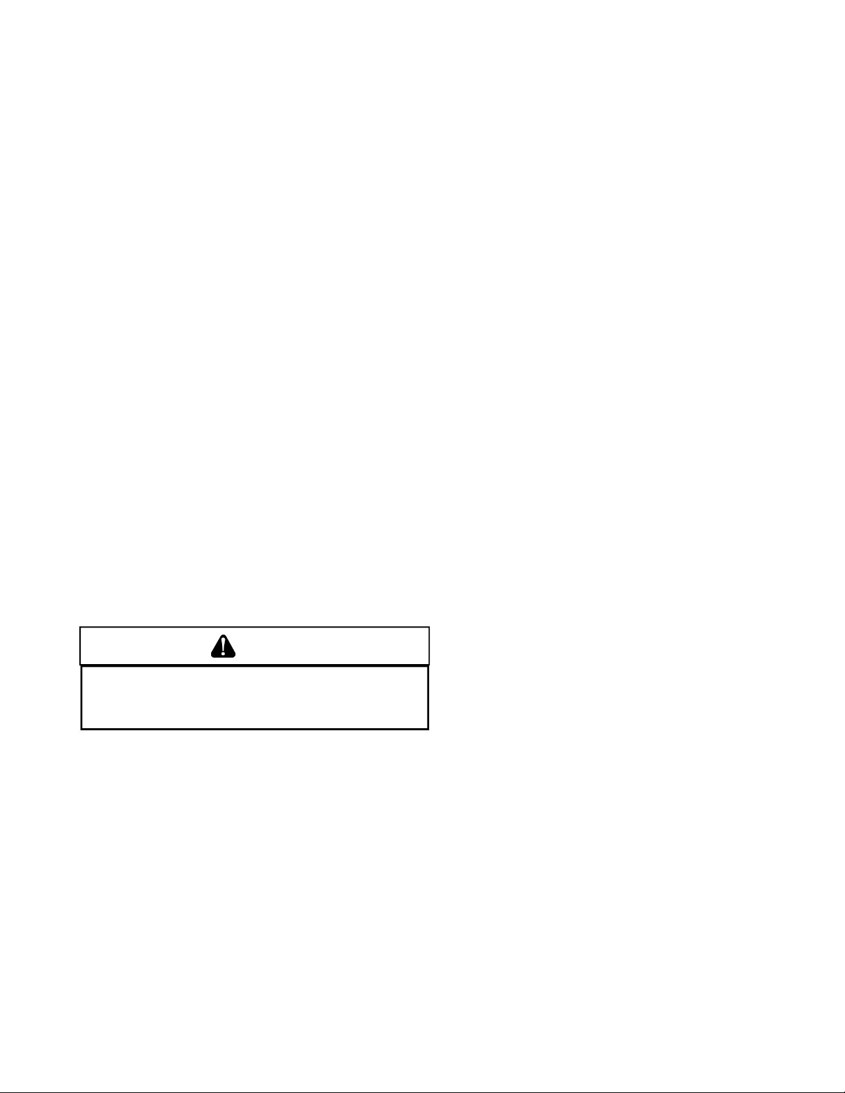
INSTALLATION CONSIDERATIONS
Corrections must be in accordance with the latest edition of
the National Fuel Gas Code NFPA 54/ANSI Z223.1 and/or
CSA B149 Installation Codes.
If resizing is required on any portion of the venting system,
use the appropriate table in Appendix G in the latest edition
of the National Fuel Gas Code ANSI Z223.1 and/or CSA B149
Installation Codes.
Thermostat Requirements
A high quality single stage thermostat with a "C" terminal is
recommended to control the G*SS9* and A*SS9* furnace.
Thermostat Location
In an area having good air circulation, locate the thermostat
about five feet high on a vibration-free inside wall. Do not
install the thermostat where it may be influenced by any of
the following:
• Drafts, or dead spots behind doors, in corners, or under cabinets.
• Hot or cold air from registers.
• Radiant heat from the sun.
• Light fixtures or other appliances.
• Radiant heat from a fireplace.
• Concealed hot or cold water pipes, or chimneys.
• Unconditioned areas behind the thermostat and dehumidistat, such as an outside wall.
(Section 9.3), or CAN/CGA B149 Installation Codes (Sections 7.2, 7.3, or 7.4), or applicable provisions of the local
building codes for determining the combustion air requirements for the appliances.
Most homes will require outside air be supplied to the furnace area by means of ventilation grilles or ducts connecting directly to the outdoors or spaces open to the outdoors
such as attics or crawl spaces.
The following information on air for combustion and ventilation
is reproduced from the National Fuel Gas Code NFPA 54/ANSI
Z223.1 Section 9.3.
9.3* Air for Combustion and Ventilation.
9.3.1 General.
9.3.1.1 Air for combustion, ventilation, and dilution of flue gases for
appliances installed in buildings shall be obtained by application of one
of the methods covered in 9.3.2 through 9.3.6. Where the requirements
of 9.3.2 are not met, outdoor air shall be introduced in accordance with
methods covered in 9.3.3 through 9.3.6.
Exception No. 1: This provision shall not apply to direct vent appliances.
9.3.1.2 Appliances of other than natural draft design and other than
Category 1 vented appliances shall be provided with combustion, ventilation, and dilution air in accordance with the appliance manufacturer’s
instructions.
9.3.1.3 Appliances shall be located so as not to interfere with proper
circulation of combustion, ventilation, and dilution air.
COMBUSTION AND VENTILATION AIR
REQUIREMENTS
WARNING
OSSIBLE PROPERTY DAMAGE, PERSONAL I NJURY OR DEATH MAY OCCUR
P
IF THE FURNACE I S NOT PROVIDED WITH ENOUGH FRESH AIR FOR PROPER
COMBUSTION AND VENTILATION OF FLUE GASES. MOST HOMES REQUIRE
OUTSIDE AIR BE SUPPLIED TO THE FURNACE AREA.
Improved construction and additional insulation in buildings
have reduced heat loss by reducing air infiltration and escape around doors and windows. These changes have helped
in reducing heating/cooling costs but have created a problem supplying combustion and ventilation air for gas fired
and other fuel burning appliances. Appliances that pull air
out of the house (clothes dryers, exhaust fans, fireplaces,
etc.) increase the problem by starving appliances for air.
When the furnace is installed as a direct vent (2-pipe) furnace, no special provisions for air for combustion are required. However, if this furnace is to be installed in the same
space with other gas appliances, such as a water heater,
ensure there is an adequate supply of combustion and ventilation air for the other appliances. Refer to the latest edition of the National Fuel Gas Code NFPA 54/ANSI Z223.1
9.3.1.4 Where used, a draft hood or a barometric draft regulator shall be
installed in the same room or enclosure as the appliance served so as to
prevent any difference in pressure between the hood or regulator and the
combustion air supply.
9.3.1.5 Makeup air requirements for the operation of exhaust fans, kitchen
ventilation systems, clothes dryers, and fireplaces shall be considered in
determining the adequacy of a space to provide combustion air requirements.
9.3.2 Indoor Combustion Air. The required volume of indoor air shall
be determined in accordance with the method in 9.3.2.1 or 9.3.2.2 except that where the air infiltration rate is known to be less than 0.40
ACH, the method in 9.3.2.2 shall be used. The total required volume
shall be the sum of the required volume calculated for all appliances
located within the space. Rooms communicating directly with the space
in which the appliances are installed through openings not furnished
with doors, and through combustion air openings sized and located in
accordance with 9.3.2.3, are considered a part of the required volume.
9.3.2.1* Standard Method. The minimum required volume shall be 50
ft 3 per 1,000/Btu/hour (4.8m3/kW).
9.3.2.2* Known Air Infiltration Rate Method. Where the air infiltration rate of a structure is known, the minimum required volume shall be
determined as follows:
15
Page 16
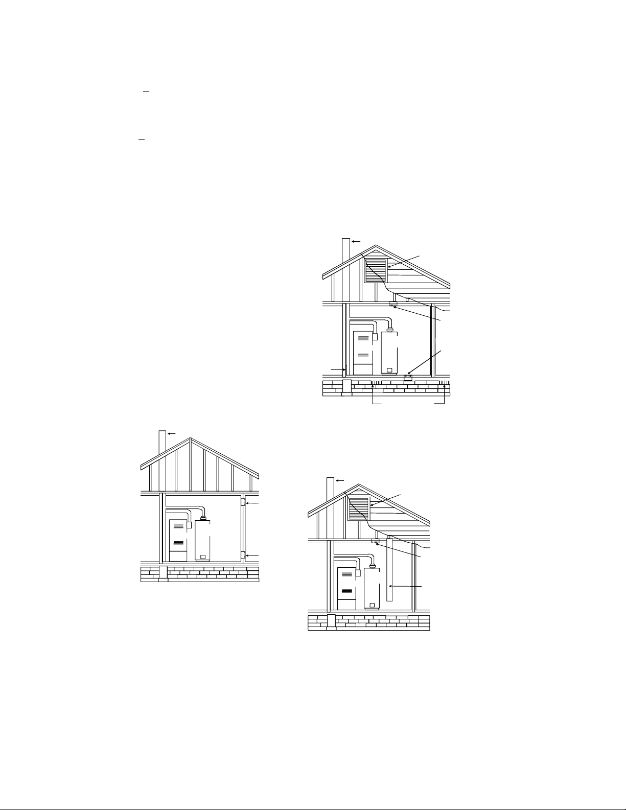
INSTALLATION CONSIDERATIONS
A
(1) For appliances other than fan-assisted, calculate using the following
equation:
Required Volume
> ________ _________
other
(2) For fan-assisted appliances, calculate using the following equation:
Required Volume
> ________ _________
fan
3
21 ft
ACH 1000 Btu/hr
15 ft
ACH 1000 Btu/hr
I
other
(
3
I
fan
(
)
)
ods in 9.3.3.1 or 9.3.3.2. The minimum dimension of air openings shall
not be less than 3 in. (80 mm).
9.3.3.1 Two Permanent Openings Method. Two permanent openings, one commencing within 12 in. (300 mm) of the top and one commencing within 12 in. (300 mm) of the bottom, of the enclosure shall be
provided. The openings shall communicate directly, or by ducts, with
the outdoors or spaces that freely communicate with the outdoors, as
follows:
where:
I
I
= all appliances other than fan-assisted input in Btu per
other
fan
hour
= fan-assisted appliances input in Btu per hour
ACH = air change per hour (percent of volume of space exchanged
per hour, expressed as a decimal)
(3) For purposes of this calculation, an infiltration rate greater than
0.60 ACH shall not be used in the equations in 9.3.2.2(1) and
9.3.2.2(2).
9.3.2.3 Indoor Opening Size and Location. Openings used to connect
indoor spaces shall be sized and located in accordance with the following:
(1)*Combining spaces on the same story. Each opening shall have a
minimum free area of 1 in.2/1000Btu/hr (2200 mm2/kW) of the total
input rating of all appliances in the space but not less than 100 in.
(0.60m2). One opening shall commence within 12 in. (300 mm) of
the top, and one opening shall commence within 12 in. (300 mm) of
the bottom, of the enclosure [see Figure A.9.3.2.3(1)]. The mini-
mum dimension of air openings shall be not less than 3 in. (80 mm).
NOTE: Each opening must have
a free area of not less than one
square inch per 1000 BTU of
the total input rating of all equipment in the enclosure, but not
less than 100 square inches.
Chimney or Gas Vent
Water
Heater
Furnace
Opening
Opening
Figure A.9.2.3.3.(1) All Combustion Air from Adjacent
Indoor Spaces through Indoor Combustion Air Openings.
(1)*Where directly communicating with the outdoors or where commu-
nicating to the outdoors through vertical ducts, each opening shall
have a minimum free area of 1 in.
2
/4000 Btu/hr (550 min2/kW) of
total input rating of all appliances in the enclosure. [See Figure
A.9.3.3.1(1)(a) and Figure A.9.3.3.1(1)(b).]
Chimney or Gas Vent
Ventilation louvers
(each end of attic)
NOTE: Th e inlet and outlet air
openings must each have a free
area of not less than one sq uare
inch per 4000 BTU of the
total input rating of all equipment
in the enclosure.
Outlet Air
Water
Heater
Furnace
2
lternate
air inlet
Ventilation louvers for
unheated crawl space
Inlet Air
Figure A.9.3.3.1(1)(a) All Combustion Air Fr om Outdoors -
Inlet Air from Ventilated Crawl Space and Outlet Air
to Ventilated Attic.
Chimney or Gas Vent
Ventilation louvers
(each end of attic)
NOTE: The inlet and outlet air
openings must each have a free
area of not less than one square
inch per 4000 BTU of the
total input rating of all equipment
in the enclosure.
Outlet Air
Water
Heater
Furnace
Inlet air duct
[ends 1 ft (300 mm)
above floor]
(2) Combining spaces in different stories. The volumes of spaces in
different stories shall be considered as communicating spaces where
such spaces are connected by one or more openings in doors or
floors having a total minimum free area of 2 in.2/1000 Btu/hr (4400
mm2/kW) of total input rating of all appliances.
9.3.3 Outdoor Combustion Air. Outdoor combustion air shall be provided through opening(s) to the outdoors in accordance with the meth-
(2)*Where communicating with the outdoors through horizontal ducts,
each opening shall have a minimum free area of 1 in.2/2000 Btu/hr
(1100 min2/kW) of total input rating of all appliances in the enclosure. [See Figure A.9.3.3.1(2).]
Figure A.9.3.3.1(1)(b) All Combustion Air
From Outdoors through Ventilated Attic.
16
Page 17
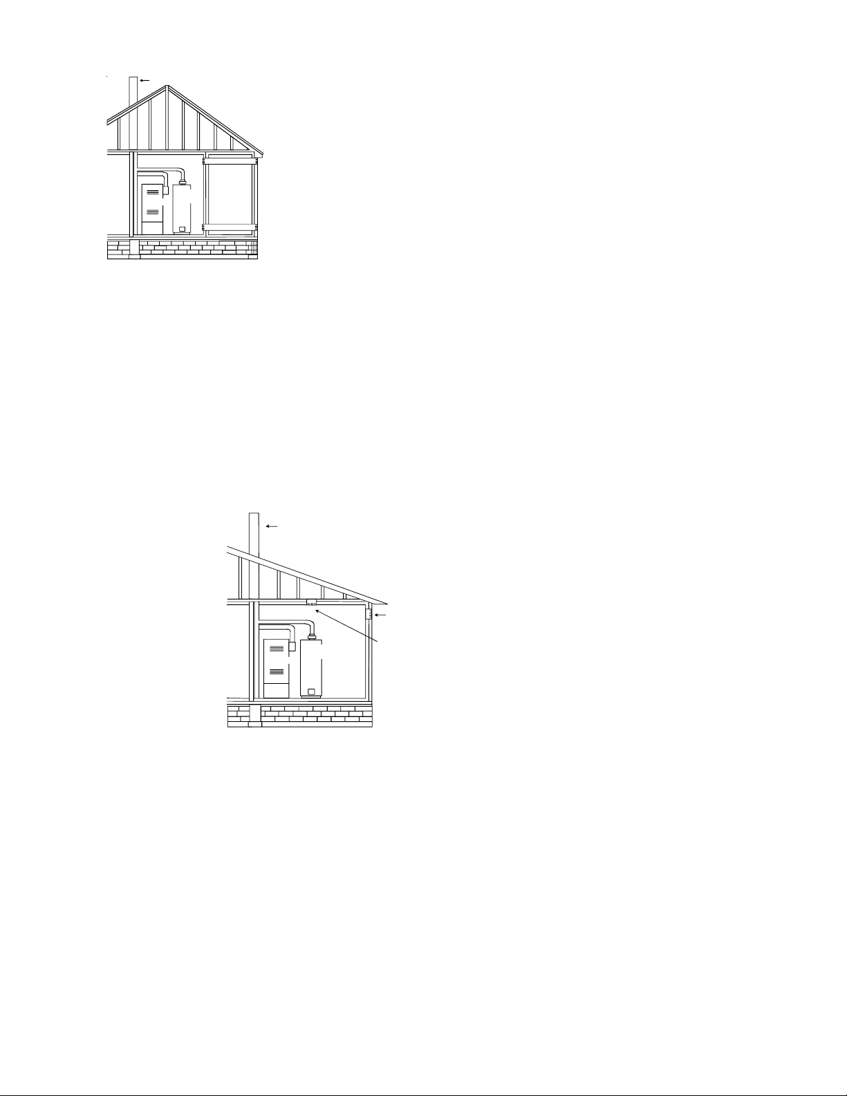
INSTALLATION CONSIDERATIONS
Chimney or Gas Vent
NOTE: The air duct openings
must have a free area of not
less th an one square inch per
2000 BTU of the total input
rating of all equipment in the
enclosure*.
Furnace
Water
Heater
Outlet air duct
Inlet air duct
Figure A.9.3.3.1(2) All Combustion Air From Outdoors
through Horizontal Ducts.
9.3.3.2* One Permanent Opening Method. One permanent open-
ings, commencing within 12 in. (300 mm) of the top of the enclosure,
shall be provided. The appliance shall have clearances of at least 1 in.
(25 mm) from the sides and back and 6 in. (150 mm) from the front of
the appliance. The opening shall directly communicate with the outdoors or shall communicate through a vertical or horizontal duct to the
outdoors or spaces that freely communicate with the outdoors (see
Figure A.9.3.3.2) and shall have a minimum free area of the following:
(1) 1 in.
2
/3000 Btu/hr (700 mm2 per kW) of the total input rating of all
appliances located in the enclosure, and
(2) Not less than the sum of the areas of all vent connectors in the
space.
NOTE: The single op ening must h ave
a free area of not less than one
square inch per 3000 BTU of
the total in put rating of all equi pment in t he enclo sure, but not less than
the sum of t he areas of all vent
connectors in the confined space.
Chimney or Gas Vent
Opening
9.3.5 Engineered Installations. Engineered combustion air installations shall provide an adequate supply of combustion, ventilation, and
dilution air and shall be approved by the authority having jurisdiction.
9.3.6 Mechanical Combustion Air Supply . Where all combustion air
is provided by a mechanical air supply system, the combustion air shall
be supplied form outdoors at the minimum rate of 0.35 ft
Btu/hr (0.034 m3/min per kW) for all appliances located within the
space.
9.3.6.1 Where exhaust fans are installed, additional air shall be provided
to replace the exhausted air.
9.3.6.2 Each of the appliances served shall be interlocked to the mechanical air supply system to prevent main burner operation where the
mechanical air supply system is not in operation.
9.3.6.3 Where combustion air is provided by the building’ s mechanical
ventilation system, the system shall provide the specified combustion
air rate in addition to the required ventilation air.
9.3.7 Louvers, Grilles, and Screens.
9.3.7.1 Louvers and Grilles. The required size of openings for com-
bustion, ventilation, and dilution air shall be based on the net free area of
each opening. Where the free area through a design of louver or grille or
screen is known, it shall be used in calculating the size opening required
to provide the free area specified. Where the louver and grille design and
free area are not known, it shall be assumed that wood louvers will have
25 percent free area, and metal louvers and grilles will have 75 percent
free area. Nonmotorized louvers and grilles shall be fixed in the open
position.
(c) The minimum size of outdoor opening(s) shall be the full size
of outdoor opening(s) calculated in accordance with 9.3.3,
multiplied by the reduction factor. The minimum dimension
of air openings shall not be less than 3 in. (80 mm).
3
/min per 1000
Alternate
Opening
Location
Furnace
Water
Heater
Figure A.9.3.3.2 All Combustion Air
From Outdoors through Single Combustion Air Opening.
9.3.4 Combination Indoor and Outdoor Combustion Air . The use of
a combination of indoor and outdoor combustion air shall be in accordance with (1) through (3) (see example calculation in Annex J]:
(1) Indoor Openings: Where used, openings connecting the interior
spaces shall comply with 9.3.2.3.
(2) Outdoor Opening(s) Location. Outdoor opening(s) shall be located
in accordance with 9.3.3.
(3) Outdoor Opening(s) Size. The outdoor opening(s) size shall be
calculated in accordance with the following:
(a) The ratio of the interior spaces shall be the available volume
of all communicating spaces divided by the required volume.
(b) The outdoor size reduction factor shall be 1 minus the ratio of
interior spaces.
9.3.7.2 Minimum Scree Mesh Size. Screens shall not be smaller than
1/4 in. mesh.
9.3.7.3 Motorized Louvers. Motorized louvers shall be interlocked
with the appliance so they are proven in the full open position prior to
main burner ignition and during main burner operation. Means shall be
provided to prevent the main burner form igniting should the louver fail
to open during burner startup and to shut down the main burner if the
louvers close during burner operation.
9.3.8 Combustion Air Ducts. Combustion air ducts shall comply with
9.3.8.1 through 9.3.8.8.
9.3.8.1 Ducts shall be constructed of galvanized steel or a material
having equivalent corrosion resistance, strength, and rigidity.
Exception: Within dwellings units, unobstructed stud and joist spaces
shall not be prohibited from conveying combustion air, provided that
not more than one fireblock is removed.
9.3.8.2 Ducts shall terminate in an unobstructed space, allowing free
movement of combustion air to the appliances.
9.3.8.3 Ducts shall serve a single space.
17
Page 18

INSTALLATION CONSIDERATIONS
tions. Refer to Vent/Flue Pipe and Combustion Air Pipe
9.3.8.4 Ducts shall not serve both upper and lower combustion air
openings where both such openings are used. The separation between
ducts servicing upper and lower combustion air openings shall be maintained to the source of combustion air.
9.3.8.5 Ducts shall not be screened where terminating in an attic space.
9.3.8.6 Horizontal upper combustion air ducts shall not slope down-
ward toward the source of combustion air.
9.3.8.7 The remaining space surrounding a chimney liner, gas vent, special gas vent, or plastic piping installed within a masonry, metal, or
factory built chimney shall not be used to supply combustion air.
Exception: Direct vent appliances designed for installation in a solid
fuel-burning fireplace where installed in accordance with the
manufacture’s installation instructions.
9.3.8.8 Combustion air intake openings located on the exterior of the
building shall have the lowest side of the combustion air intake openings
located at least 12 in. (300 mm) vertically from the adjoining grade level.
section in the installation instructions for details concerning
the conversion to the alternate vent/flue and combustion air
connections on the 90% furnace.
The 34.5" single stage furnace is one of the products in our
newly redesigned line of shorter chassis furnaces. It is available in 92% / 96% AFUE up flow / horizontal model and a
down flow / horizontal model.
The up flow / horizontal 34.5" single stage furnace is available in the following models:
*MSS920402BNAA
*MSS920603BNAA
*MSS9S0803BNAA
*MSS920804CNAA
*MSS920805CNAA
*MSS921004CNAA
*MSS921005CNAA
*MSS921205DNAA
Horizontal Applications and Considerations
Horizontal applications, in particular, may dictate many of
the installation’s specifics such as airflow direction, ductwork connections, flue and/or combustion air pipe connections, etc. The basic application of this furnace as a horizontal furnace differs only slightly from an upright installation. When installing a furnace horizontally, additional consideration must be given to the following:
Drain Trap and Lines
In horizontal applications the condensate drain trap is secured to the furnace side panel, suspending it below the
furnace. A minimum clearance of 5.5" below the furnace
must be provided for the drain trap. Additionally, the appropriate downward piping slope must be maintained from the
drain trap to the drain location. Refer to Condensate Drain
Trap and Lines section in this manual or the installation
instructions for further details. If the drain trap and drain line
will be exposed to temperatures near or below freezing, adequate measures must be taken to prevent condensate from
freezing. NOTE: The use of insulation and/or heat tape is
recommended. Failure to provide proper condensate drainage can result in property damage.
Leveling
Leveling ensures proper condensate drainage from the heat
exchanger and induced draft blower. For proper flue pipe
drainage, the furnace must be level lengthwise from end to
end. The furnace should also be level from back to front or
have a slight tilt with the access doors downhill (approximately 3/4") from the back panel. The slight tilt allows the
heat exchanger condensate, generated in the recuperator
coil, to flow forward to the recuperator coil front cover.
In horizontal installations with the furnace laying on the left
hand side, the alternate vent connection may be used. In
this configuration the internal elbow is removed. The standard piping connections may also be used in these posi-
*MSS960402BNAA
*MSS960603BNAA
*MSS960803BNAA
*MSS960804CNAA
*MSS960805CNAA
*MSS961005CNAA
*MSS961205DNAA
The down flow / horizontal 34.5" single stage furnace is available in the following models.
*CSS920402BNAA
*CSS920603BNAA
*CSS920804CNAA
*CSS921005CNAA
*CSS960402BNAA
*CSS960603BNAA
*CSS960804CNAA
*CSS961005CNAA
*CSS961205CNAA
18
Page 19

INSTALLATION CONSIDERATIONS
A
A
IR
DISCHARGE
Side
Return
Duct
Connection
Bottom
Return
Duct
Connection
Side
Return
Duct
Connection
UPFLOW
UPRIGHT
Bottom
Return
Duct
Connection
UPFLOW HORIZONTAL
LEFT AIR DISCHARGE
DISCHARGE
UPFLOW HORIZONTAL
RIGHT AIR DISCHARGE
AIR
Bottom
Return
Duct
Connection
COUNTERFLOW HORIZONTAL
RIGHT AIR DISCHARGE
AIR
DISCHARGE
COUNTERFLOW HORIZONTAL
LEFT AIR DISCHARGE
DISCHARGE
Bottom
Return
Duct
Connection
90% Furnace Recommended Installation Positions
Propane Gas and/or High Altitude Installations
P
OSSIBLE PROPERTY DAMAGE, PERSONAL I NJURY OR DEATH MAY OCCUR IF
THE CORRECT CONV ERSION KITS ARE NOT I NSTALLED.
MUST BE APPLIE D TO INSURE SAFE AND PROPER FURNAC E OPERATION.
CONVERSIONS MUST BE PERFORMED BY A QUALIFIED INSTALLER OR SERVICE
AGENCY.
This furnace is shipped from the factory configured for natural gas at standard altitude. Propane gas installations require an orifice change to compensate for the energy content difference between natural and propane gas.
High altitude installations may require both a pressure switch
IR
and an orifice change. These changes are necessary to compensate for the natural reduction in the density of both the
gas fuel and the combustion air at higher altitude.
Refer to the Accessories Charts in this manual or product
Specification Sheet for a tabular listing of appropriate
manufacturer’s kits for propane gas and/or high altitude installations. The indicated kits must be used to insure safe
and proper furnace operation. All conversions must be performed by a qualified installer, or service agency.
VENT/FLUE PIPE AND COMBUSTION AIR PIPE
WARNING
THE APPROPRIATE KITS
ALL
NOTE: Alternate "vertical" piping connections can not be
used when an upflow 90% furnace is installed with supply
air discharging to the right or when a counterflow furnace is
installed with supply discharging to the left. In this case,
use the standard flue and combustion air piping connections
Alternate Electrical and Gas Line Connections
Furnaces have provisions allowing for electrical and gas line
connections through either side panel. In horizontal applications the connections can be made either through the “top”
or “bottom” of the furnace.
Drain Pan
A drain pan must be provided if the furnace is installed above
a conditioned area. The drain pan must cover the entire area
under the furnace (and air conditioning coil if applicable).
Freeze Protection
If the drain trap and drain line will be exposed to temperatures near or below freezing, adequate measures must be
taken to prevent condensate from freezing. NOTE: The use
of insulation and/or heat tape is recommended. Failure to
provide proper condensate drainage can result in property
damage.
WARNING
FAILURE TO FOLLOW THESE INSTRUCTIONS CAN RESULT IN BODILY INJURY OR
DEATH.
CAREFU LLY RE AD AND FOLLOW AL L INST RUCTI ONS GI VEN IN THIS
SECTION.
WARNING
UPON COMPLETION OF THE FURNACE INSTALLATI ON, CAREFULLY INSPECT THE
ENTIRE FLUE SYSTEM BO TH INSIDE AND OUTSIDE THE FURNACE TO ASSURE IT
IS PROPERLY SEALED.
PERSONAL INJURY OR DEATH DUE TO E XPOSURE TO FLUE PRODUCTS,
INCLUDING CARBON MONOXIDE.
LEAKS IN THE FLUE SYSTEM CAN RESULT IN SERIOUS
A condensing gas furnace achieves its high level of efficiency
by extracting almost all of the heat from the products of
combustion and cooling them to the point where condensation takes place. Because of the relatively low flue gas temperature and water condensation requirements, PVC pipe
is used as venting material.
This furnace must not be connected to Type B, BW, or L
vent or vent connector, and must not be vented into any
portion of a factory built or masonry chimney except when
used as a pathway for PVC as described later in this section. Never common vent this appliance with another appli-
ance or use a vent which is used by a solid fuel appliance.
It is the responsibility of the installer to follow the manufacturers’ recommendations and to verify that all vent/flue piping and connectors are compatible with furnace flue products. Additionally, it is the responsibility of the installer to
19
Page 20

INSTALLATION CONSIDERATIONS
ensure that all piping and connections possess adequate
structural integrity and support to prevent flue pipe separation, shifting, or sagging during furnace operation.
Dual Certification: Non-Direct/Direct Vent (90%
Furnaces Only)
The 90% furnace is dual certified and may be installed as a
non-direct vent (single pipe) or direct vent (dual pipe) appliance. A non-direct vent installation requires only a vent/
flue pipe. A direct vent installation requires both a vent/
flue pipe and a combustion air intake pipe. Refer to the appropriate section for details concerning piping size, length,
number of elbows, furnace connections, and terminations.
WARNING
T
O AVOID BODI LY INJURY, FIRE OR E XPLOSION, SOLVENT CEMENTS MUST BE
KEPT AWAY FROM ALL IGNITION SOURCES (I.E., SPARKS, OPEN FLAMES, AND
EXCESSIVE HEAT) AS THEY ARE COMBUS TIBLE LIQUIDS.
CEMENT VAPORS OR CONTACT WITH SKIN AND/OR EYES.
A
VOID BREATHING
• The combustion air intake termination of a direct vent
NOTE: In Canada, the B149 Fuel Gas Code takes precedence over the preceding termination restrictions.
Direct Vent Installations
On upflow units secure the combustion air intake pipe directly to the air intake coupling. On counterflow units secure the combustion air intake pipe to the air intake coupling using the rubber coupling and worm gear hose clamps
provided with the unit. The counterflow rubber coupling allows service removal of air intake piping internal to the furnace blower compartment. The combustion air intake pipe
can also be secured directly to the counterflow unit air intake pipe coupling.
create a nuisance or hazard or could be detrimental
to the operation of regulators, relief valves, or other
equipment.
application should not terminate in an area which is
frequently dusty or dirty.
Precautions should be taken to prevent condensate from
freezing inside the vent/flue pipe and/or at the vent/flue pipe
termination. It is our recommendation that all vent/flue piping
exposed to temperatures below 35°F for extended periods
of time should be insulated with 1/2” thick closed cell foam.
Also all vent/flue piping exposed outdoors in excess of the
terminations shown in this manual (or in unheated areas)
should be insulated with 1/2” thick closed cell foam. Inspect
piping for leaks prior to installing insulation.
The following bullets and diagram describe the restrictions
concerning the appropriate location of vent/flue pipe and combustion air intake pipe (when applicable) terminations. Refer to the installation instructions for specific details on termination construction.
• All terminations must be located at least 12 inches
above ground level or the anticipated snow level.
• Vent terminations must terminate at least 3 feet above
any forced air inlet located within 10 feet.
NOTE: This provision does not apply to the combustion air intake termination of a direct vent application.
• The vent termination of a non-direct vent application
must terminate at least 4 feet below, 4 feet horizontally from, or 1 foot above any door, window, or gravity
air inlet into any building.
• The vent termination of a direct vent application must
terminate at least 12 inches from any opening through
which flue gases may enter a building (door, window,
or gravity air inlet).
• The vent termination of vent pipe run vertically through
a roof must terminate at least 12 inches above the
roof line (or the anticipated snow level) and be at least
12 inches from any vertical wall (including any anticipated snow build up).
• A vent termination shall not terminate over public walkways or over an area where condensate or vapor could
Non-Direct Vent Installations
A minimum of one 90° elbow must be installed on the combustion air intake “coupling” to guard against inadvertent
blockage.
WARNING
HE RUBBER ELBOW IS NOT DESIGNED TO SUPPORAT A LOAD. WHEN THE
T
RUBBER ELBOW IS MOUNTED EXTERNALLY TO THE FURNACE CABINET,
EXTREME CARE MUST BE TAKEN TO ADEQUATELY SUPPORT FIELD- SUPPLIED
VENT/FLUE PIPING, AS DAMAGE CAN RESULT IN LEAKS CAUSING BODILY
INJURY OR DEATH DUE TO EXPOSURE TO FLUE GASES, INCLUDI NG CARBON
MONOXIDE.
CAUTION
E SURE NOT TO DAMAGE INTERNAL WIRING OR OTHER COMPONENTS WHEN
B
REINSTALLING COUPLING AND SCREWS.
Vent/Flue Pipe Lengths and Diameters
Refer to the following tables for applicable length, elbows,
and pipe diameter for construction of the vent/flue pipe system of a non-direct vent installation. In addition to the vent/
flue pipe, a single 90° elbow must be secured to the combustion air intake to prevent inadvertent blockage. The tee
or elbows used in the vent/flue termination must be included
when determining the number of elbows in the piping system.
20
Page 21

INSTALLATION CONSIDERATIONS
*MSS9*/*CSS9 Direct Vent (2-Pipe)
& Non-Di r ect Ve nt (1-Pipe)
Maximum allowable Length of Vent/Flue Pipe
& Combustion Air Pipe (Ft)
Model
*MSS9*0402BNA*
*MSS9*0603BNA*
*MSS9*0803BNA*
*MSS9*0804CNA*
*MSS9*0805CNA*
*MSS921004CNA*
*MSS921005CNA*
*MSS961005CNA*
*MSS9*1205DNA* 3" 238 231 224 217 210 20 3 196 189
Pipe
12345678
Size
2" 145 140 135 130 125 120 115 110
3" 238 231 224 217 210 203 196 189
2" 220 215 210 205 200 195 190 185
3" 224 217 210 203 196 189 182 175
2" 95 90 85 80 75 70 65 60
3" 238 231 224 217 210 203 196 189
2" 95 90 85 80 75 70 65 60
3" 238 231 224 217 210 203 196 189
2" 45 40 35 30 25 20 15 10
3" 217 210 203 196 189 182 175 168
2" 45 40 35 30 25 20 15 10
3" 217 210 203 196 189 182 175 168
Number of Elbows
(6)
(1) (2)
(3) (5)
may be required. Use 1/2” thick closed cell foam insulation
such as Armaflex or Insultube where required.
Vent/Flue Pipe Terminations
The vent/flue pipe may terminate vertically, as through a roof,
or horizontally, as through an outside wall.
Vertical vent/flue pipe termination should be as shown in the
following figures. Refer to Vent/Flue Pipe and Combustion
Air Pipe - Termination Locations section in this manual or
the installation instructions for details concerning location
restrictions. The penetration of the vent through the roof must
be sealed tight with proper flashing such as is used with a
plastic plumbing vent.
NOTE: Terminate both pipes in the same pressure zone
(same side of roof, no major obstacles between pipes,
etc.).
TEE (OPTIONAL)
Model
*CSS9*0402BNA*
*CSS9*0603BNA*
*CSS9*0804CNA*
*CSS9*1005CNA*
*CSS9*1205DNA* 3" 238 231 224 217 210 203 196 189
1) Maximum allowable limits listed on individual lengths for inlet and flue and
NOT a combination.
2) Minimum requirement for each vent pipe is five (5) feet in length and one
elbow/tee.
3) Tee used in the vent/flue termination must be included when determining
the number of elbows in the piping system.
4) 2 1/2” or 3” diameter pipe can be used in place of 2” diameter pipe.
5) Increased Clearance Configurations using (2) 45 deg. Long Sweep elbows
should be considered equivalent to one 90 deg. elbow.
6) One 90° elbow should be secured to the combustion air intake connection.
Pipe
12345678
Size
2" 145 140 135 130 125 120 115 110
3" 238 231 224 217 210 203 196 189
2" 120 115 110 105 100 95 9 0 85
3" 224 217 210 203 196 189 182 175
2" 95 90 85 80 75 70 65 60
3" 238 231 224 217 210 203 196 189
2" 25 20 15 10 5 n/a n/a n/a
3" 238 231 224 217 210 203 196 189
Vent/Flue and Combustion Air Pipe Lengths and Diameters
Refer to the preceding table for applicable length, elbows,
and pipe diameter for construction of the vent/flue and combustion air intake pipe systems of a non-direct vent (single
pipe) installation. The number of elbows tabulated represents the number of elbows and/or tees in each (Vent/Flue
& Combustion Air Intake) pipe. Elbows and/or tees used in
the terminations must be included when determining the number of elbows in the piping systems.
If the combustion air intake pipe is to be installed above a
finished ceiling or other area where dripping of condensate
will be objectionable, insulation of the combustion air pipe
COMBUSTION AIR INTAKE
(OPTIONAL)
*Not required for
single pipe installation
E
N
I
L
F
O
O
R
INTAKE
SCREEN
OPTIONAL
12” MIN TO ROOF OR HIGHEST
ANTICIPATED SNOW LEVEL
STRAIGHT
6
9
ELBOWS
12” MIN
HEIGHT DIFFERENCE
BETWEEN
INTAKE AND VENT
”
3
-
.
X
A
M
”
.
N
I
M
Horizontal vent/flue pipe terminations should be as shown in
the following figure. Refer to Vent/Flue Pipe and Combus-
tion Air Pipe - Termination Locations section in this manual
or the installation instructions for details concerning location restrictions. A 2 3/8" diameter wall penetration is required for 2" diameter pipe while a 3 1/2" diameter hole is
required for 3" diameter pipe. To secure the pipe passing
through the wall and prohibit damage to piping connections,
a coupling should be installed on either side of the wall and
solvent cemented to a length of pipe connecting the two
couplings. The length of pipe should be the wall thickness
plus the depth of the socket fittings to be installed on the
inside and outside of the wall. The wall penetration should
be sealed with silicone caulking material.
21
Page 22

INSTALLATION CONSIDERATIONS
V
12" MIN.
VENT/FLUE TEE (
TURNED DOW N or
90° ELBOW TURNED
12 " MIN. ABOVE
HIGHEST ANTICIPATED
SNOW LEVEL
Horizontal Termination (Single Pipe)
Above Highest Anticipated Snow Level
10”- 24”
or
45° ELBO W
DOWN
OPTIONAL)
Combustion Air Intake may also be snorkeled to obtain 12” min ground
clearance.
Alternate Vent Termination Above Anticipated Snow Level
Alternate Horizontal Vent Termination (Dual Pipe)
90°
ELBOWS
3”-24” BETWEEN PIPES
AIR
INTAKE
SCREEN
(OPTIONAL)
12" MI N. ABOVE
HIGHEST ANTICIPATED
SNOW LEVEL
(Dual Pipe)
6” MAX
4” MIN
90º OR 45°
ELBOW
SCREEN
(OPTIONAL)
12" MIN. TO GRADE O R
HIGHEST ANTICIPATED
SNOW LEVEL
Standard Horizontal Terminations (Dual Pipe)
90°
ELBOWS
3” - 24”
12" MINIMUM
ENT/FLUE TEE
OR
90° ELBOW TURNED
DOWN
12" MINIMUM ABOVE
HIGHEST ANTICIPATED
SNOW LEVEL
90% Furnace Horizontal Termination (Single Pipe)
Above Highest Anticipated Snow Level
In a basement installation, the vent/flue pipe can be run between joist spaces. If the vent pipe must go below a joist
and then up into the last joist space to penetrate the header,
two 45° elbows should be used to reach the header rather
than two 90° elbows.
Direct Vent (Dual Pipe) Piping
AIR
INTAKE
SCREEN
(OPTIONAL)
12" MIN. ABOVE
HIGHE ST ANTICIPATED
SNOW LEVEL
Direct vent installations require both a combustion air intake and a vent/flue pipe. The pipes may be run horizontally
and exit through the side of the building or run vertically and
22
Page 23

INSTALLATION CONSIDERATIONS
exit through the roof of the building. The pipes may be run
through an existing unused chimney; however, they must
extend a minimum of 12 inches above the top of the chimney. The space between the pipes and the chimney must
be closed with a weather tight, corrosion resistant flashing.
Both the combustion air intake and a vent/flue pipe terminations must be in the same atmospheric pressure zone. Refer to Vent/Flue and Combustion Air Pipe - Termination Lo-
cations or Concentric Vent Termination section in this manual
or the installation instructions for specific details on termination construction.
Concentric Vent Kits (
DCVK) Application
The DCVK-20 and DCVK-30 kit is designed to allow the
terminations of a direct vent furnace to be “concentrically”
vented through a wall or roof. This kit allows a single penetration to support terminations for both the vent/flue pipe
and the combustion air intake pipe.
(DCVK) Vent Termination Clearances
1. Determine termination locations based on clearances
specified in furnace installation instructions, and following
steps as shown in Figures 1,3,6,7,8 and 9.
9"
12"
Direct Vent
Terminal
50,000 Btuh
or less
12"
12"
Direct Vent Terminal
More than 50,000 Btuh
FIGURE 1
2. The vent termination must be located at least 12” above
ground or normally expected snow accumulation levels.
3. Do NOT terminate over public walkways. Avoid areas
where condensate may cause problems such as above
planters, patios, or adjacent to windows where steam
may cause fogging.
4. The vent termination shall be located at least 4’
horizontally from any electric meter, gas meter, regulator
and any relief equipment. These distances apply ONLY
to U.S. Installations.
3'
A
R
G
Forc e d A ir Inlet
These kits are for vertical or horizontal termination of the
combustion air inlet and the exhaust vent pipes on Category
IV gas-fired condensing furnaces. The DCVK-30 kit can be
used for 3” diameter pipe systems. The DCVK-20 kit can
be used for the 2” diameter pipe system. For the correct
pipe size for the furnace. Both the combustion air inlet and
the exhaust vent pipes must attach to the termination kit.
The termination kit must terminate outside the structure and
must be installed per the instructions outlined below for
vertical or horizontal termination. Vertical termination is
preferred. Field supplied pipe and fittings are required to
complete the installation.
1. Determine the best location for the termination kit. Roof
termination is preferred since it is less susceptible to
damage, has reduced intake contaminants and less visible vent vapors. For side termination, consideration
should be given to:
E
D
Roof Boot/Flashing
(Field Supplied)
3" or 4" Diame ter
SDR-26 Pipe
2" or 3" Diam eter
Y Concentric Fittin g
2 or 2 1/2" Diam eter
SDR-26 Pipe
2" or 3" Diameter
Rain Cap
FIGURE 2
TABLE 1
a. Possible damage from the vapors to plants/shrubs,
other equipment and building materials
b. Possible damage to the terminal from foreign ob-
jects
c. Wind effects that may cause recirculation of flue
products, debris or light snow
d. Visible vent vapors.
Vent
Maintain 12" (18" for Canada)
minimum clearance above highest
anticipated snow level. Maximum of
Combustion Air
24" above roof.
Support (Field Supplied)
5. The vent termination shall be located at least 3’ above
any forced air inlet located within 10’; and at least 10’
from a combustion air intake of another appliance, except
another direct vent furnace intake.
6. In Canada, the Canadian Fuel Gas Code takes
precedence over the preceding termination instructions.
Vent
FIGURE 3
45 Elbow
(Field Supplied)
Combustion Air
23
Page 24

INSTALLATION CONSIDERATIONS
Drain Information for Horizontal Installations
WARNING
DO NOT OPERATE THE FURNACE WITH THE RAIN CAP REMOVED AS
RECIRUCLATION OF THE FLUE GASES MAY OCCUR.
COLLECT INSIDE THE LARGER COMBUSTIN A IR PIPE AND FLOW TO THE
BURNER ENCLOSURE.
PROPERTY DAMAGE, EQUIPMENT DAMAGE, PERSONAL INJURY OR DEATH.
F
AILURE TO FOLLOW THIS WARNING CAN RESULT IN
WATER MAY ALSO
Concentric Sidewall Vent Kit (0170K00000S)
This (sidewall only) vent kit is to be used with 2” - 3” vent
systems. The vent kit must terminate outside the structure
and may be installed with the intake and exhaust pipes located side-by side or with one pipe above the other. This kit
is NOT intended for use with single pipe (non-direct vent)
installations.
Condensate Drain Lines and Drain Trap
A condensing gas furnace achieves its high level of efficiency
by extracting almost all of the heat from the products of
combustion and cooling them to the point where condensation takes place. The condensate which is generated must
be piped to an appropriate drain location.
NOTE: Horizontal installations require 5.5" under the furnace to accommodate the drain trap. The horizontal furnace
must be installed with ¾" slope from back to front to permit
condensate flow towards the front of the furnace.
When installing a *MSS9* horizontally with the left side
down, there are two options for connecting the vent pipe to
the furnace.
Option 1
Venting may be connected to the furnace vent pipe fitting on
the original top (now the end) of the furnace.
Option 2
The internal vent pipe and elbow may be removed from the
furnace to permit the vent to exit the top (original side) of the
furnace. If this option is used, an RF000142 Vent-Drain coupling must be used to keep condensate from collecting in
the inducer assembly.
To install the drain, refer to the following instructions and
illustration.
1. Remove screws from vent flange.
2. Remove internal elbow and vent pipe.
3. Cut pipe 2 1/2" from flange.
4. Remove cabinet plug adjacent to inducer outlet and install an original cabinet vent hole.
5. Install RF000142 coupling on inducer outlet.
6. Install flanged vent section removed in step 2 and secure with clamps.
7. Secure flange to cabinet using screws removed in
step 1.
R 000142F
Insert flange. Cut 2 ½” long.
WARNING
N UPRIGHT UPFLOW INS TALLATIONS, THE DRAIN TRAP MUST BE MOUNTED ON
I
THE OPPOSITE S IDE OF THE UNIT FROM THE JUNCTION BOX.
REDUCE THE RISK OF WATE R REACHING THE JUNCTION BOX I N THE EVENT OF
A BLOCKED DRAIN CONDITION.
CAN RESULT IN PO SSIBLE PROPERTY DAMAGE, PERSONAL I NJURY, OR DEATH
DUE TO ELECT RIC AL SHOC K.
AILURE TO FOLLOW THESE INSTRUCTIONS
F
HIS WILL
T
• If the drain line is routed through an area which may
see temperatures near or below freezing, precautions must be taken to prevent condensate from
freezing within the drain line.
• If an air conditioning coil is installed with the
furnace, a common drain may be used. An open
tee must be installed in the drain line, near the
cooling coil, to relieve positive air pressure from the
coil’s plenum. This is necessary to prohibit any
interference with the function of the furnace’s drain
trap.
24
Page 25

INSTALLATION CONSIDERATIONS
the gas is artificially derated, the appropriate orifice size
must be determined based upon the BTU/ft
derated gas and the altitude. Refer to the National Fuel
Gas Code, NFPA 54/ANSI Z223.1, and information provided by the gas supplier to determine the proper orifice
size.
A different pressure switch may be required at high altitude
regardless of the BTU/ft
the product Specification Sheet or Technical Manual for a
tabular listing of appropriate altitude ranges and corresponding manufacturer’s pressure switch kits.
PROPANE GAS CONVERSION
GAS SUPPLY AND PIPING
The furnace rating plate includes the approved furnace gas
input rating and gas types. The furnace must be equipped to
operate on the type of gas applied. This includes any conversion kits required for alternate fuels and/or high altitude.
CAUTION
P
OSSIBLE PROPERTY DAMAGE, PERSONAL INJURY OR DEATH MAY OCCUR IF
THE CORRECT CONVERSION KITS ARE NOT INSTALLED.
MUST BE APPLIED TO I NSURE SAFE AND PROPER FURNACE OPERATION.
CONVERSIONS MUST BE PERFORMED BY A QUALIFIED INSTALLER OR SERVICE
AGENCY.
3
content of the
3
content of the fuel used. Refer to
WARNING
HE APPROPRIATE KITS
T
A
LL
O PREVENT UNRELI ABLE OPERATION OR EQUIPMENT DAMAGE, THE INLET
T
GAS SUPPLY PRESSURE MUST BE AS SPECIFIED ON THE UNIT RATING PLATE
WITH ALL OTHE R HOUSEHOLD GAS FIRED APPLI ANCES OPERATING.
Inlet gas supply pressures must be maintained within the
ranges specified below. The supply pressure must be constant and available with all other household gas fired appliances operating. The minimum gas supply pressure must
be maintained to prevent unreliable ignition. The maximum
must not be exceeded to prevent unit overfiring.
INLET GAS SUP PLY PRESSURE
Natural Gas Minimum: 4.5" w.c. Maximum: 10.0" w.c.
Propane Gas Minimum: 11.0" w.c. Maximum: 13.0" w.c.
HIGH ALTITUDE DERATE
When this furnace is installed at high altitude, the appropriate High Altitude orifice kit must be applied. This is required
due to the natural reduction in the density of both the gas
fuel and combustion air as altitude increases. The kit will
provide the proper design certified input rate within the specified altitude range.
High altitude kits are purchased according to the installation altitude and usage of either natural or propane gas. Refer
to the product Specification Sheet or Technical Manual for a
tabular listing of appropriate altitude ranges and corresponding manufacturer’s high altitude (Natural, Propane gas, and/
or Pressure Switch) kits.
Do not derate the furnace by adjusting the manifold pressure to a lower pressure than specified on the furnace rating
plate. The combination of the lower air density and a lower
manifold pressure will prohibit the burner orifice from drawing the proper amount of air into the burner. This may cause
incomplete combustion, flashback, and possible yellow tipping.
In some areas the gas supplier may artificially derate the
gas in an effort to compensate for the effects of altitude. If
This unit is configured for natural gas. The appropriate
manufacturer’s propane gas conversion kit, must be applied for propane gas installations.
**SS9* models using a White-Rodgers 36J22 single stage
valve use LPM-07 LP Conversion Kit.
GAS VALVE
This unit is equipped with a 24 volt gas valve controlled
during furnace operation by the integrated control module.
As shipped, the valve is configured for natural gas. The
valve is field convertible for use with propane gas by using
the appropriate propane gas conversion kit. Taps for measuring the gas supply pressure and manifold pressure are
provided on the valve.
NOTE: The gas supply pressure on White-Rodgers "J"
model gas valve, used on single stage furnaces, can
be checked with a gas pressure test kit (Part
#0151K00000S) available through our authorized distributors.
The gas valve has a manual ON/OFF control located on the
valve itself. This control may be set only to the “ON” or
“OFF” position. Refer to the Lighting Instructions Label or
the “Putting the Furnace Into Operation” section of this
manual or the installation instructions for use of this control during start up and shut down periods.
GAS PIPING CONNECTIONS
CAUTION
T
O AVOID POSSI BLE UNSATISFAC TORY OPERATI ON OR EQUIPMENT DAMAGE
DUE TO UNDERFIRING OF EQUIPMENT, USE THE PROPER SIZE OF
NATURAL/PROPANE GAS PIPING NEEDED WHEN RUNNING PIPE FROM THE
METER/TANK TO THE FURN ACE.
The gas piping supplying the furnace must be properly sized
based on the gas flow required, specific gravity of the gas,
25
Page 26

INSTALLATION CONSIDERATIONS
g
)
and length of the run. The gas line installation must comply
with local codes, or in their absence, with the latest edition
of the National Fuel Gas Code, NFPA 54/ANSI Z223.1.
O AVOID THE POSSIBLITY OF EXPLOSION OR F IRE, NEVER USE A MATCH
Natural Gas Capacity of Pipe
In Cubic Feet of Gas Per Hour (CFH)
Length of
Pipe i n Feet 1/ 2" 3/4" 1" 1 1/4" 1 1/2"
10
20
30
40
50
60
70
80
90
100
(Pressure 0.5 psig or l ess and press ure drop of 0. 3" W.C. ; Based on 0.60
Specific Gravity Gas)
BTUH Furnace Input
CFH =
Heatin
132 278 520 1050 1600
92 190 350 730 1100
73 152 285 590 980
63 130 245 500 760
56 115 215 440 670
50 105 195 400 610
46 96 180 370 560
43 90 170 350 530
40 84 160 320 490
38 79 150 305 460
Value of Gas (BTU/Cubic Foot
Nominal B lac k Pipe Siz e
T
OR OPEN FLAME TO TEST FOR LEAKS.
Check for leaks using an approved chloride-free soap and
water solution, an electronic combustible gas detector, or
other approved testing methods.
NOTE: Never exceed specified pressures for testing. Higher
pressure may damage the gas valve and cause subsequent
overfiring, resulting in heat exchanger failure. Disconnect
this unit and shutoff valve from the gas supply piping system before pressure testing the supply piping system with
pressures in excess of 1/2 psig (3.48 kPa). Isolate this unit
from the gas supply piping system by closing its external
manual gas shutoff valve before pressure testing supply piping system with test pressures equal to or less than 1/2
psig (3.48 kPa).
PROPANE GAS TANKS AND PIPING
WARNING
To connect the furnace to the building’s gas piping, the installer must supply a ground joint union, drip leg, manual
shutoff valve, and line and fittings to connect to gas valve.
In some cases, the installer may also need to supply a
transition piece from 1/2" pipe to a larger pipe size.
The following stipulations apply when connecting gas piping. Refer to the following figures for typical gas line connections to the furnace.
1. Use black iron or steel pipe and fittings for the building piping.
2. Use pipe joint compound on male threads only. Pipe
joint compound must be resistant to the action of the
fuel used.
3. Use ground joint unions.
4. Install a drip leg to trap dirt and moisture before it can
enter the gas valve. The drip leg must be a minimum
of three inches long.
5. Install a 1/8" NPT pipe plug fitting, accessible for test
gage connection, immediately upstream of the gas
supply connection to the furnace.
6. Use two pipe wrenches when making connection to
the gas valve to keep it from turning. The orientation
of the gas valve on the manifold must be maintained
as shipped from the factory .
7. Install a manual shutoff valve between the gas meter
and unit within six feet of the unit. If a union is installed, the union must be downstream of the manual
shutoff valve, between the shutoff valve and the furnace.
8. Tighten all joints securely .
GAS PIPING CHECKS
Before placing unit in operation, leak test the unit and gas
connections.
26
WARNING
ROPANE GAS IS HEAVIER THAN AIR AND ANY LEAKING GAS CAN SETTLE IN
P
ANY LOW AREAS OR CONFINED SPACES.
PERSONAL INJURY, OR DEATH DUE TO FIRE OR EXPLOSION CAUSED BY A
PROPANE GAS LEAK, INSTALL A GAS DETECTION WARNING DEVICE.
TO PREVENT PROPERTY DAMAGE,
A gas detecting warning system is the only reliable way to
detect a propane gas leak. Iron oxide (rust) can reduce the
level of odorant in propane gas. Do not rely on your sense of
smell. Contact a local propane gas supplier about installing
a gas detecting warning system. If the presence of gas is
suspected, follow the instructions on this page.
All propane gas equipment must conform to the safety standards of the National Board of Fire Underwriters, NBFU
Manual 58.
For satisfactory operation, propane gas pressure must be
10 inch WC at the furnace manifold with all gas appliances
in operation. Maintaining proper gas pressure depends on
three main factors:
1. Vaporization rate, depending on temperature of the liquid, and “wetted surface” area of the container or containers.
2. Proper pressure regulation. (Two-stage regulation is recommended for both cost and efficiency).
3. Pressure drop in lines between regulators, and between
second stage regulator and the appliance. Pipe size will
depend on length of pipe run and total load of all appliances.
Complete information regarding tank sizing for vaporization,
recommended regulator settings, and pipe sizing is available from most regulator manufacturers and propane gas
suppliers.
Use pipe dope approved for use with L.P. gas.
Refer to the following illustration for typical propane gas in-
stallations and piping.
Page 27

INSTALLATION CONSIDERATIONS
First Stage
Regulator
200 PSIG
Maximum
5 to 15 PSIG
(20 PSIG Max.)
Continuous
Second Stage
Regulator
11" W.C.
Typical Propane Gas Installation
WARNING
I
F THE GAS FURNACE IS INSTALLED IN A BASEMENT, AN EXCAVATED
AREA OR A CONFINED SPACE, IT IS STRONGLY REC OMMENDED TO
CONTACT A PROPANE SUPPLIER TO INSTALL A GAS DETECTING
WARNING DEVICE IN CASE OF A GAS LEAK.
•
SINCE PROPANE GAS I S HEAVIER THAN AIR, ANY LEAKING GAS CAN
SETTLE IN ANY LOW AREAS OR CONFINED SPACES.
PROPANE GAS ODORANT MAY FADE, MAKING THE GAS UNDETE CTABLE
•
EXCEPT WITH A WARNING DEVICE.
WARNING
F THE INFORMATION IN THESE INSTRUCTIONS IS NOT FOLLOWED EXACTLY, A
I
FIRE OR EXPLOSION MAY RESULT CAUS ING PROPERTY DAMAGE, PERSONAL
INJURY OR LOSS OF LIFE.
O NOT STORE OR USE GASOLINE OR OTHER FLAMMABLE VAPORS AND
–
D
LIQU IDS IN THE V ICINI TY OF THIS OR AN Y OTHE R AP PLIAN CE.
–
WHAT TO DO IF YOU SMELL GAS
•
•
PHONE IN YOUR BUILDING.
•
PHONE.
•
DEPARTMENT.
–
NSTALLATION AN D SERVICE MUST BE PE RFORMED BY A QUALIFI ED INST ALLER,
I
SERVICE AGENCY OR THE GAS SUPPLIER.
O NOT TRY TO LIGHT ANY APPLIAN CE.
D
O NOT TOUCH ANY ELECTRICAL SWITCH; DO NOT USE ANY
D
MMEDIATELY CALL YOUR GAS SUPPLIER FROM A NEIGHBOR’S
I
FOLLO W THE GAS SUPPLI ER’S IN STRUCT IONS.
F YOU CANNOT REACH Y OUR GAS SUPPLIER, CA LL THE FIRE
I
:
Sizing Betw een Firs t and Second Stage Regulator*
Maximum P r opane C apaci ti es li st ed ar e based on 2 psi g pr es sur e dr op at 10 ps i g sett ing .
Capacities in 1,000 BTU/hour.
Pipe or
Tubing
Length
Feet
10 730 1,700 3,200 5,300 8,300 3,200 7,500
20 500 1,100 220 3,700 5,800 2,200 4,200
30 400 920 2,000 2,900 4,700 1,800 4,000
40 370 850 1,700 2,700 4,100 1,600 3,700
50 330 770 1,500 2,400 3 ,700 1,500 3,400
60 300 700 1,300 2,200 3 ,300 1,300 3,100
80 260 610 1,200 1,900 2,900 1,200 2,600
100 220 540 1,000 1,700 2,600 1,000 2,300
125 200 490 900 1,400 2,300 900 2,100
150 190 430 830 1,300 2,100 830 1,900
175 170 400 780 1,200 1,900 770 1,700
200 160 380 730 1,100 1,800 720 1,500
To conv er t to c apac it i es at 15 psig se ttin gs -multip ly by 1 .130
To convert to c apaciti es at 5 psig s ett ings -multiply by 0.879
Sizing Betw een Second or Second Stage Re gulator & Appliance*
Maxi mum Pro pane Capa cit ies li st ed are bas ed on 1/2" W.C. pres sur e dr op at 11" W.C. setti ng.
Capacities in 1,000 BTU/hour.
Pipe or
Tubing
Length
Feet
3/8" 1/2" 5/8" 3/4" 7/8" 1/2" 3/4" 1" 1-1/4" 1- 1/2"
10 39 92 199 329 501 275 567 1,071 2,205 3,307
20 26 62 13 1 216 346 189 393 732 1,496 2,299
30 21 50 107 181 277 152 315 590 1,212 1,858
40 19 41 90 145 233 129 267 504 1,039 1,559
50 18 3 7 79 131 198 114 237 448 913 1,417
60 16 3 5 72 1,211 187 103 217 409 834 1,275
80 13 2 9 62 10 4 155 89 18 5 346 724 1,066
100 11 26 55 90 138 78 16 2 307 630 976
125 10 24 48 81 122 69 14 6 275 567 866
150 9 21 43 72 109 63 132 252 511 787
200 8 19 39 66 100 54 112 209 439 665
250 8 17 36 60 93 48 100 185 390 590
*Dat a in accor dance w ith NF PA pam ph le t N o. 54
Tubing Size, O.D. Type L
3/8" 1/2" 5/8" 3/4" 7/8" 1/2" 3/4"
Tubing Size, O.D. Type L
Nominal Pipe S ize
Nominal Pipe
Size
Sche dule 40
Sche dule 40
Propane Gas Piping Charts
When installing a propane storage tank, the contractor must
consider proper tank sizing, safety, efficiency, ground characteristics and aesthetics. For a residential customer, the
size may range from 100-1,000 gallons, depending on household use. Typically, a 500 gallon tank is ample for an average four-bedroom home. However, it is best to consult your
local propane supplier to ensure the proper sizing for propane storage requirements. Determining the correct tank
size for each household is a function of demand, economy,
efficiency and convenience. It is a process that requires
cooperation between the propane supplier and customer.
ELECTRICAL CONNECTIONS
WARNING
TO AVOID THE RISK OF ELECTRICAL SHOCK, WIRING TO THE UNIT MUST BE
PROPERLY POLARIZED AND GROUNDED.
27
Page 28

INSTALLATION CONSIDERATIONS
Connect hot, neutral, and ground wires as shown in the wir-
WARNING
HIGH VOLTAGE
D
ISCONNECT ALL POWER BEFORE SERVICING OR
INSTALLI NG THIS UNIT.
BE PRESENT.
DAMAGE, PERSONAL INJURY OR DEATH.
L
ABEL ALL WIRES PRIOR TO DISCONNECTION WHEN SERVICING CONTROLS.
WIRING ERRORS CAN COUSE IMPROPER AND DANGEROUS OPERATION.
ERIFY PROPER OPERATION AFTER SERVICING.
V
MULTIPLE POWER SOURCES MAY
FAILURE TO DO SO MAY CAUSE PROPERTY
CAUTION
ing diagram located on the unit’s blower door. Line polarity
must be observed when making field connections. Line voltage connections can be made through either the right or left
side pan.
NOTE: Wire routing must not interfere with circulator blower
operation, filter removal, or routine maintenance.
WARNING
WIRING HARNESS
The wiring harness is an integral part of this furnace. Field
alteration to comply with electrical codes should not be required. Wires are color coded for identification purposes.
Refer to the wiring diagram for wire routings. If any of the
original wire as supplied with the furnace must be replaced,
it must be replaced with wiring material having a temperature rating of at least 105° C. Any replacement wiring must
be copper conductor.
115 VOLT LINE CONNECTIONS
Before proceeding with electrical connections, ensure that
the supply voltage, frequency, and phase correspond to that
specified on the unit rating plate. Power supply to the furnace must be N.E.C. Class 1, and must comply with all
applicable codes. The furnace must be electrically grounded
in accordance with local codes or, in their absence, with the
latest edition of The National Electric Code, ANSI NFPA 70
and/or The Canadian Electric Code CSA C22.1.
Use a separate fused branch electrical circuit containing
properly sized wire, and fuse or circuit breaker. The fuse or
circuit breaker must be sized in accordance with the maximum overcurrent protection specified on the unit rating plate.
An electrical disconnect must be provided at the furnace
location.
NOTE: Line polarity must be observed when making field
connections.
N
G
I
N
W
R
A
IN 90% FURNACE UPRIGHT UPFLOW INSTALLATIONS, THE DRAIN TRAP MUST
BE MOUNTED ON THE OPPOSITE SIDE OF THE UNIT FROM THE JUNCTION
BOX.
THIS WILL REDUCE THE RISK OF WATER REACHING THE JUNCTION
BOX IN THE EVENT OF A BLOCKED DRAIN CONDITION.
TO AVOID THE RISK OF ELECTRICAL SHOCK, INJURY, OR DEATH, THE
FURNACE MUST BE ELECTRICALLY GROUNDED IN ACCORDANCE WITH LOCAL
CODES OR, IN THEIR ABSENCE, WITH THE LATEST EDITION OF THE
N
ATIONAL ELECTRIC CODE.
WARNING
HIGH VOLTAGE
ISCONNECT
D
CHANGING A NY ELECTRICAL WI RING.
SOURCES MAY BE PRESENT.
PROPERTY DAMA GE, PERSONAL INJURY OR DEATH.
POWER BEFORE SERVICING OR
ALL
MULTIPLE POWER
FAILURE TO DO S O MAY CAUSE
24 VOLT HUMIDIFIER
A 24 volt humidifier can be connected to the normally open
terminal of the main pressure switch. The humidifier common would then be connected to "C" on the control board
low voltage terminal strip.
If it is necessary for the installer to supply additional line
voltage wiring to the inside of the furnace, the wiring must
conform to all local codes, and have a minimum temperature
rating of 105°C. All line voltage wire splices must be made
inside the furnace junction box.
24 VOLT THERMOSTAT WIRING
NOTE: Low voltage connections can be made through either
the right or left side panel. Wire routing must not interfere
with circulator blower operation, filter removal, or routine maintenance.
A 40 V.A. transformer and an integrated electronic control
are built into the furnace to allow use with most cooling equipment. Consult the wiring diagram, located in the Technical
Manual or on the blower door for further details of 115 Volt
and 24 Volt wiring.
28
THERMOSTAT WIRING
The single stage furnace will have a "W" terminal and will
use a single stage thermostat. The following drawing illus-
Page 29

INSTALLATION CONSIDERATIONS
trates the typical field wiring for a heat only single stage
system and a single stage heating/single stage cooling
system. Refer to the following figures for proper connections to the integrated control module.
CIRCULATING AIR AND FILTERS
DUCTWORK - AIR FLOW
Duct systems and register sizes must be properly designed
for the C.F.M. and external static pressure rating of the
furnace. Ductwork should be designed in accordance with
the recommended methods of "Air Conditioning Contractors of America" manual D.
A duct system should be installed in accordance with Standards of the National Board of Fire Underwriters for the Installation of Air Conditioning, Warm Air Heating and Ventilating Systems, Pamphlets No. 90A and 90B.
A return air filter is not supplied with the furnace. The installer must supply a means of filtering all of the return air.
Filter(s) shall comply with UL900 or CAN/ULC-S111 Standards. If the furnace is installed without filters, the warranty
will be voided.
Upflow furnaces with air delivery of less than 1800 CFM:
Use one side return or one bottom return ductwork connection.
Upflow furnaces with air delivery of 1800 CFM or higher:
Use two side returns or one side return and one bottom
return connection.
Guide dimples locate the side and bottom return cutout
locations. Use a straight edge to scribe lines connecting
the dimples. Cut out the opening on these lines. An undersized opening will cause reduced airflow. For bottom return
connection, remove the bottom of the cabinet before setting the furnace on the raised platform or return air duct.
A closed return duct system must be used, with the return
duct connected to the furnace. NOTE: Ductwork must never
be attached to the back of the furnace. Supply and return
connections to the furnace may be made with flexible joints
to reduce noise transmission, if desired. If a central return
is used, a connecting duct must be installed between the
unit and the utility room wall so the blower will not interfere
with combustion air or draft. The room, closet, or alcove
must not be used as a return air chamber.
When the furnace is used in connection with a cooling unit,
the furnace should be installed in parallel with or on the
upstream side of the cooling unit to avoid condensation in
the heating element. With a parallel flow arrangement, the
dampers or other means used to control the flow of air must
be adequate to prevent chilled air from entering the furnace
and, if manually operated, must be equipped with means
to prevent operation of either unit unless the damper is in
the full heat or cool position.
When the furnace is heating, the temperature of the return
air entering the furnace must be between 55°F and 100°F.
UPRIGHT FILTER INSTALLATIONS
Depending on the installation and/or customer preference,
differing filter arrangements can be applied. Filters can be
installed in the central return register and a side panel external filter rack kit (upflow filter kit # EFR02). As an alternative a media air filter or electronic air cleaner can be used
as the requested filter. Refer to the following minimum filter
requirement charts for determination of the minimum filter
area to ensure proper unit performance. The following
figures show possible filter locations. NOTE: A ductwork
access door must be used in counterflow applications to
allow filter removal. If the filter rack is used, the side of the
plenum must be at least as tall as dimension "A" shown in
the following illustration. For dimension of "A" refer to the
following chart.
Refer to Minimum Filter Area tables to determine filter area
requirement. NOTE: Filters can also be installed elsewhere
in the duct system such as a central return.
Horizontal Installations
Filter(s) must be installed external to the furnace casing for
horizontal installations. For most installations it is preferable to use a central return with filters installed in the duct
behind the return air grill. In this way filter replacement is
relatively simple by merely removing the grille, rather than
going into the attic or crawl space.
ADDITIONAL FILTERING ACCESSORIES
External Filter Rack Kit (EFR02)
The external filter rack kit is intended to provide a location
external to the furnace casing, for installation of a permanent filter on upflow model furnaces. The rack is designed
to mount over the indoor blower compartment area of either
side panel, and provide filter retention as well as a location
for attaching return air ductwork.
Electronic Air Cleaner (ASAS and GSAS) or Media
Air Cleaner (AMU and GMU)
The electronic air cleaner and media air cleaner are multipositional high efficiency air filtration devices that can be
29
Page 30

INSTALLATION CONSIDERATIONS
installed in any position, except with the access door facing down. The best location for the air cleaner is in the
return air duct next to the blower compartment. Before installing the air cleaner, consider the application. The electronic air cleaner must be readily accessible for periodic
inspection and cleaning of the pre-filters and electronic cells
while the media air cleaner must be readily accessible for
periodic inspection and replacement of the Media Air Cleaner
(AMU and GMU) filter cartridge (3 per carton) M0-1056,
M1-1056, M2-1056, M8-1056, to maintain maximum efficiency and trouble-free operation. Carbon Filters 1156-3
and 1856-3 (set of 3) are also available. See Product Catalog for exact filter for your model.
NORMAL SEQUENCE OF OPERATION
POWER UP
1. 115 V AC power applied to furnace.
2. Integrated ignition control module performs internal
checks.
3. Integrated ignition control module LED will light.
4. Integrated ignition control monitors safety circuits continuously .
5. Furnace awaits call from thermostat.
NORMAL HEATING SEQUENCE
1. R and W thermostat contacts close, initiating a call for
heat.
2. Integrated control module performs safety circuit
checks.
3. The induced draft blower is energized causing pressure switch contacts to close. Induced draft blower
remains energized for pre-purge period.
4. Ignitor warm up begins after pre-purge is completed.
The ignition control has a WARM UP PERIOD OF 17
SECONDS.
5. Gas valve opens at end of ignitor warm up period, delivering gas to burners to establish flame.
6. The control checks for a signal from the flame sensor
within seven (4) seconds after the gas valve is energized. Gas will only continue to flow if a flame signal is
present.
7. Circulator blower is energized on heat speed following
a fixed thirty (30) second blower on delay .
8. Furnace runs, integrated control module monitors safety
circuits continuously.
9. R and W thermostat contacts open, allowing the gas
valve to cycle off.
10. Induced draft blower is de-energized following a fifteen
(15) -second post purge.
1 1. Circulator blower is de-energized following heat off de-
lay period.
12. Furnace awaits next call from thermostat.
Cooling Mode
The normal operational sequence in cooling mode is as follows:
1. R and Y thermostat contacts close, initiating a call for
cool.
2. Integrated control module performs safety circuit checks.
3. Outdoor fan and compressor are energized.
4. Circulator blower is energized on cool speed following a
fixed five (5) second on delay.
5. Furnace circulator blower and outdoor cooling unit run,
integrated control module monitors safety circuits continuously.
6. R and Y thermostat contacts open, completing the call
for cool.
7. Outdoor fan and compressor are de-energized.
8. Circulator blower is de-energized following a fixed forty
five (45) second cool off delay period.
9. Furnace awaits next call from thermostat.
Fan Only Mode
The normal operational sequence in fan only mode is as
follows:
1. R and G thermostat contacts close, initiating a call for
fan.
2. Integrated control module performs safety circuit checks.
3. Circulator blower is energized on heat speed. Electronic air cleaner terminals are energized.
4. Circulator blower runs, integrated control module monitors safety circuits continuously.
5. R and G thermostat contacts open, completing the call
for fan.
6. Furnace awaits next call from thermostat
7. Furnace awaits next call from thermostat.
30
Page 31

SYSTEM OPERATION
HEATING - Abnormal Operation
The following presents the probable causes of questionable furnace operation and how to fix them. Look through
the observation window in the blower access door and
make a note of the number of flashes in sequence between pauses. Next, refer to the Troubleshooting Chart
on the following pages for an interpretation of the LED
signals and to the information in this section for a description of the problem.
1. Internal Control Failure with Integrated Ignition
Control. Check for voltage to the furnace and low voltage at the control board. Check for blown fuse on the
control board. If the control determines it has an internal fault, it enters a locked-out state. Any of the situations mentioned will cause the diagnostic LED to provide no signal. The control board should only be re-
placed after all other checks from the Troubleshooting
Chart have been verified.
2. System Lockout. If a flame is not sensed during the
first seven (4) seconds after the gas valve is energized, the control turns off the gas. There will then be
a 30 second delay while the induced draft blower is
energized to purge the heat exchanger. The ignitor will
next be energized and preheated. The gas valve will
then be energized. If flame is not sensed in seven (4)
seconds the gas valve will be de-energized and another
purge will occur. The control will cycle the gas valve a
total of three (3) times before it determines it cannot
establish measurable combustion and enters a locked
out state. The diagnostic light code for this problem is
one short flash followed by a longer pause. The control can be reset and brought out of lockout mode by
turning the thermostat off for more than (5) seconds
and less than (20) seconds and then back on. It can
also be reset by turning off the electrical disconnect
switch to the furnace for a minimum of 5 seconds.
NOTE: The control board will automatically reset one hour
after lockout occurs. If the furnace frequently has to be
reset, it means that a problem exists that should be corrected. Refer to Troubleshooting Chart on the following
pages for aid in determining the cause.
3. Pressure Switch Stuck Closed. If the control senses
the pressure switch is closed when the induced draft
blower is off, it waits until the fault is corrected. The
diagnostic light code for this problem is 2 flashes. The
probable cause is either a faulty pressure switch or wiring.
4. Pressure Switch Stuck Open. If, after the induced draft
blower is energized, the pressure switch does not close
within 5 minutes, the control will go into a 1-hour lockout. The control will automatically reset from lockout and
restart the ignition sequence. The diagnostic light code
for this problem is three short flashes followed by a
pause. The probable causes are either disconnected
hose to the pressure switch, faulty pressure switch or
wiring, or restricted air intake or flue piping.
5. Open Primary or Auxiliary Limit. If the limit control
opens, the air circulator blower will be turned on until
the limit closes. The induced draft blower will turn off for
5 seconds then turn off. The diagnostic light code for
this problem is four short flashes followed by a pause.
The probable cause is either low conditioned air flow
due to dirty filter or resistance in duct work, faulty limit,
faulty blower, or blower speed set to low.
6. Flame Sensed with No Call for Heat. If the control
senses a flame when the gas valve is de-energized, it
will run the air circulation blower and the induced draft
blower continuously with no further furnace operation.
The diagnostic flash code for this is a five flashes. The
probable causes are either a short to ground in flame
sense circuit, miswiring, lingering burner flame or a slow
closing gas valve.
7. Open Rollout Limit. If the rollout control opens, the air
circulator blower will be energized all the time. The diagnostic light code for this problem is six flashes followed by a pause. The probable cause is either restricted flue piping or improper air requirements.
8. Low Flame Sense Signal. If the furnace continues to
operate and the micro-amp signal from the flame sensor falls below specified level, the diagnostic light code
for this problem will be seven flashes followed by a
pause. The probable cause is either a coated/oxidized
sensor, incorrectly positioned sensor in burner flame
or lazy burner flame due to improper gas pressure or
combustion air.
9. Igniter circuit or poor ground. Improperly connected
igniter, bad igniter or poor ground to the equipment.
The diagnostic light code for this problem is eight
flashes.
31
Page 32

ACCESSORIES
EXTERNAL FILTER RACK ( EFR02 )
EFR02 EXTERNAL FILTER RACK KIT
Used on Models
90% Upflow Mode l F u r naces
FRONT
OF UNIT
UNIT SIDE
PANEL
SLOTS IN FILTER
CLEAR SCREWS
ON UNIT
SIDE WALL VENT KIT (0170K00000S/0170K00001S)
SIDE WALL VENT KIT (0170K00000S)
This side wall only vent kit #0170K00000S is to be used
with 2” - 3” vent systems. This kit is NOT intended for use
with single pipe (indirect vent) installations.
The vent kit must terminate outside the structure and may
be installed with the intake and exhaust pipes located sideby-side or with one pipe above the other.
See the section in this manual under "Vent Flue and Combustion Air Pipe Terminations" for more information or consult the Installation Instructions (IO-635).
SIDE WALL VENT KIT (0170K00001S)
This side wall only vent kit #0170K00001S is to be used
with 2” vent systems. This kit is NOT intended for use with
single pipe (indirect vent) installations.
The vent kit must terminate outside the structure and may
be installed with the intake and exhaust pipes located sideby-side or with one pipe above the other.
See the section in this manual under "Vent Flue and Combustion Air Pipe Terminations" for more information or consult the Installation Instructions (IO-805).
LOWER EDGE
SCREW
Horizontal Installation
Vertical In s ta lla tio n
32
Page 33

ACCESSORIES
CONCENTRIC VENT CONVERSION KIT
(CVENT-2 (DCVK-20)
The CVENT-2 (DCVK-20) (2") or
the CVENT-3 (DCVK-30) (3") is a
concentric vent kit approved with
furnaces listed in this manual.
This concentric vent kit allows for
vertical or horizontal vent termination. The illustrations give a brief
view of the kit and its application.
See the section in this manual
under "Vent Flue and Combustion
Air Pipe Terminations" for more
information or consult the Installation and Operating Instructions
(IO-619*).
CVENT-3 (DCVK-30)
Combustion Air
Roof Boot/Flashing
(Field Supplied)
Vent
Vent
DCVK
Maintain 12" (18" for Canada)
minimum clearance above highest
anticipated snow level. Maximum of
24" above roof.
Support (Field Supplied)
45 Elbow
(Field Supplied)
Combustion Air
Vent
Combus tion A ir
Strap
(Field Supplied)
45 Elbow
(Field Supplied)
(Vertical Installation)
Combustion Air
Vent
Flush to
1" maximum
DCVK
(Horizontal Installation)
33
Page 34

ACCESSORIES
r
GOODMAN® and AMANA® BRAND *MSS9*/*CSS9* Model Furance Accessories
MODEL
NUMBER
Description
*MSS9*0402BNAA
EFR02
AMU / GMU
0170K00001S
ASAS / GSAS
0170K00000S
DCVK-20 (CVENT-2)
Rack
EFR External Filter
●●● ● ●●●(1) ●●●
Media Air Cleaners
Flush Mount Vent Kit
Concentric Side Wall
Electronic Air Cleane
Concentric Side Wall
(2")
Concentric Ve nt Kit
Flush Mount Vent Kit
Concentric Ve nt Kit
LPM07
CFSB-17
CFSB-21
CFSB-24
LPLP03
AFE16-60A
RF000142
DCVK-30 (CVENT-3)
(3")
LP Low Pressure
Shut Off Kit
Drain Coupling
Dual Fuel Board
Propane Gas
Convers ion Kit
Down Flow Base
Down Flow Base
Down Flow Base
*MSS9*0603BNAA
*MSS9*0803BNAA
*MSS9*0804CNAA
*MSS9*0805CNAA
*MSS921004CNAA
*MSS9*1005CNAA
*MSS9*1205DNAA
*CSS9*0402BNAA
*CSS9*0603BNAA
*CSS9*0804CNAA
*CSS9*1005CNAA
*CSS961205DNAA
●●● ● ●●●(1) ●●●
●●● ● ●●●(1) ●●●
●●● ● ●●●(1) ●●●
●●● ● ●●●(1) ●●●
●●● ● ●●●(1) ●●●
●●● ● ●●●(1) ●●●
●●● ● ●(1) ●●●
●● ● ●●●(1) ● ●●●
●● ● ●●●(1) ● ●●●
●● ● ●●●(1) ● ●●●
●● ● ●●●(1) ● ●●●
●● ● ●(1) ●●●●
(1) Required above 7,000 Ft alti t ude
34
Page 35

ACCESSORY WIRE DIAGRAMS
HIGH VOLTAGE!
DISCONNECT ALL POWER BEFORE SERVICING OR INSTALLING THIS
UNIT. MULTIPLE POWER SOURCES MAY BE PRESENT. FAILURE TO
DO SO MAY CAUSE PROPERTY DAMAGE, PERSONAL INJURY OR DEATH.
ALL FUEL SYSTEM CONTROL BOARD - AFE1860A
POWER SUPPLY
INPUT
FURNACE DEMAND
OUTPUT
BLOWER FAN DEMAND
OUTPUT
POWER SUPPLY I NPUT
(COMMON)
SECOND STAGE FURNACE
DEMAND OUTPUT
COMPRE SSOR OUTPUT
SECOND STAGE
COMPRE SSOR OUTPUT
REVERSING VALVE
OUTPUT
POWER SUPPLY OUT
TO THERMOSTAT
CALL FOR
REVERSING VALVE
CALL FOR
COMPRE S SOR
CALL FOR
EMERGENCY HEAT
CALL FOR
BLOWER FAN
CALL FOR
FURNACE HEAT
POWER SUPPLY COMMON
OUT TO THERMOSTAT
CALL FOR 2ND STAGE
FURNACE HEAT
CALL FOR 2ND STAGE
COMPRE S SOR
POWER SUPPLY OUT
TO HP CONTROL
HP CALL FOR FURNACE
(DURING DEFROST)
REVERSING
VALVE OUTPUT
COMPRE S SOR
CONTACTOR OUTPUT
POWER SUPPLY COMMON
OUT TO HP CONTROL
ODT (OUTDOOR
THERMOSTAT)
2ND STAGE CO MPRESSOR
DEMAND OUTPUT
F
U
R
N
A
C
E
T
H
E
R
M
O
S
T
A
T
H
E
A
T
P
U
M
P
R
W1
G
C
W2
Y
Y2
O
R
O
Y
E
G
W1
C
W2
Y2
R
W2
O
Y
C
OT-NO
OT-NC
OT-C
Y2
P1-8
P1-7
P1-4
P1-6
P1-5
P1-2
P1-3
P1-1
P2-2
P2-1
P2-7
P2-8
P2-5
P2-9
P2-3
P2-4
P2-6
P3-9
P3-8
P3-7
P3-2
P3-6
P3-3
P3-1
P3-4
P3-5
24VAC
24VAC
F1
3A
C
C
24VAC
C
POWER
SUPPLY
1.0K
6.8K
6.8K
+5VDC
E/W1
O
Y
+VDC
+5VDC
+VDC
K1
K2
Q1
MICROPROCESSOR
24VAC
+VDC
K4
Q2
W1-FURN
W2-HP
G-STAT
G-FURN
Y2-HP
Y2-STAT
Y2-FURN
Y-ST AT
Y-FURN
Y-HP
K3
BREAK FOR ODT
1 2
ALL FUEL SYSTEM CONTROL BOARD - AFE18-60A
This wiring diagram is for reference only. Not all wiring is as shown above.
Refer to the appropriate wiring diagram for the unit being serviced.
(For use with Heat Pumps in conjunction with 80% or 90% Single-Stage or Two-Stage Furnaces)
35
Page 36

ACCESSORY WIRE DIAGRAMS
(
(
HIGH VOLTAGE!
DISCONNECT ALL POWER BEFORE SERVICING OR INSTALLING THIS
UNIT. MULTIPLE POWER SOURCES MAY BE PRESENT. FAILURE TO
DO SO MAY CAUSE PROPERTY DAMAGE, PERSONAL INJURY OR DEATH.
For installations made prior to 2/1/11
Install
jumpers here
for GMH,
AMH, GDH,
GCH
W1
W2
8F -3
( )
N
L
HER O AT
CONN C ON
TWI
(1 C L) Y1
(1 H ) 1
(2N D H 2
(2ND C L) Y2
( U )R
-
(C N) C
STAT AN ON SETTI 0.1
-
Contro
T nning
Sensor
Fan/LE
O
FLA
FLA
FLA T
FA
GN
RED
T'
( )
( )
( )
BL
( )
T'
( )
( )
( )
( )
O
FA
SI
( )
( )
(-)
(+)
BL
RED
Sensor
Fan/LE
BL
BL
R C
R C
( r )
( r )
ace 1
Furnace 2
Black - High
Blue - Med./High
Orange - Med./Low
Red - Low
Wire as above for
GCH hybrid furnaces.
GMH, AMH, GDH AND
For GMH, AMH, GDH, GCH
FURNACE TWINING KIT - FTK03A (Johnson Control Board)
This wiring diagram is for reference only. Not all wiring is as shown above.
Refer to the appropriate wiring diagram for the unit being serviced.
(For use only with 80% or 90% Single-Stage Furnaces)
36
Page 37

ACCESSORY WIRE DIAGRAMS
HIGH VOLTAGE!
DISCONNECT ALL POWER BEFORE SERVICING OR INSTALLING THIS
UNIT. MULTIPLE POWER SOURCES MAY BE PRESENT. FAILURE TO
DO SO MAY CAUSE PROPERTY DAMAGE, PERSONAL INJURY OR DEATH.
For installations made after 2/1/11
FURNACE TWINING KIT - FTK04 (UTEC Control Board)
This wiring diagram is for reference only. Not all wiring is as shown above.
Refer to the appropriate wiring diagram for the unit being serviced.
(For use only with 80% or 90% Single-Stage Furnaces)
NOTE: Not compatible with PCBBF112 Control Boards.
37
Page 38

SERVICING
SERVICE NUMBERS
S-1 CHECKING VOLT AGE........................................................................................................................... 44
S-2 CHECKING WIRING .............................................................................................................................. 44
S-3A THERMOST AT AND WIRING ................................................................................................................. 44
S-3B HEA TING ANTICIPA TOR ........................................................................................................................ 44
S-4 CHECKING TRANSFORMER AND CONTROL CIRCUIT ........................................................................ 45
S-10B CAPACIT ANCE CHECK ......................................................................................................................... 45
S-15 CHECKING CAPACITOR ....................................................................................................................... 45
S-15A RESISTANCE CHECK ........................................................................................................................... 45
S-16A CHECKING AIR CIRCULA T OR BLOWER MOTOR (PSC) ...................................................................... 46
S-200 CHECKING DUCT STA TIC ..................................................................................................................... 46
S-201 CHECKING TEMPERATURE RISE........................................................................................................ 46
S-300 CHECKING PRIMARY LIMIT CONTROL ................................................................................................ 47
S-302 CHECKING FLAME ROLLOUT CONTROL ............................................................................................ 48
S-303 INDUCED DRAFT BLOWER MOTOR .................................................................................................... 49
S-304 CHECKING GAS VAL VE (REDUNDANT)............................................................................................... 49
S-305 CHECKING MAIN BURNERS ................................................................................................................ 49
S-306 CHECKING ORIFICES ........................................................................................................................... 49
S-307 CHECKING GAS PRESSURE ............................................................................................................... 50
S-308 CHECKING HOT SURFACE IGNITOR ................................................................................................... 52
S-309 CHECKING FOR FLASHBACK.............................................................................................................. 52
S-310 CHECKING PRESSURE SWITCH ......................................................................................................... 52
S-31 1 HIGH ALTITUDE APPLICA TION (USA) ................................................................................................... 53
S-312 CHECKING FOR DELAYED IGNITION................................................................................................... 53
S-313 CHECKING INTEGRATED IGNITION CONTROL BOARDS .................................................................. 53
S-314 CHECKING FLAME SENSOR ............................................................................................................. 54
38
Page 39

SERVICING
V
V
As more and more electronic's are introduced to the Heating Trade, Polarization of incoming power and phasing
of primary to secondary voltage on transformers becomes
more important.
Polarization has been apparent in the Appliance industry
since the introduction of the three prong plug, however,
the Heating Industry does not use a plug for incoming
power, but is hard wired.
Some of the electronic boards being used today, with
flame rectification, will not function properly and/or at all
without polarization of incoming power. Some also require phasing between the primary and secondary sides
of step-down transformers.
We recommend that these two items be checked during
normal installation and/or service calls. See as follows:
CHECKING FOR PHASING - PRIMARY TO SECONDARY OF UNMARKED TRANSFORMERS*
METER READS
24 VOLTS
.
.
.
.
.
.
VOLT / OHM
METER
METER READS
120 VOLTS
VOLT / OHM
METER
INCOMING POWER
GND
METER READS
0 VOLTS
GND
VOLT / OHM
METER
THIS IS THE COMMON
OR NEUTRAL LEG
METER READS
120 VOLTS
THIS IS L1 OR THE
HOT POWER LEG
These then should be wired to the furnace accordingly.
Some transformers will display phasing symbols as shown
D
N
G
VOLT / OHM
METER
C
R
N
L1
C
R
TRANSFORMER
D
N
G
SECONDARY
VOLT / OHM
METER
LI NE VO LTAGE
(NEUTRAL)
PRIMARY
LINE VOLTAGE
L1 (HOT)
READS 144 VOLTS - OUT OF PHASE
OLT / OHM
METER
READS 96 VOLTS - IN PHASE
D
N
G
C
R
OLT / OHM
METER
N
L1
If meter reads approximately 96 volts - the primary to secondary are in phase - if reads approximately 144 volts out of
phase - reverse low voltage wires.
*NOTE: For flame rectification the common side of the secondary voltage (24 V) is cabinet grounded. If you were to
bench test a transformer the primary neutral and secondary common must be connected together for testing purposes.
D
N
G
C
NEUTRAL
in the illustration to the left to assist in determining proper
transformer phasing.
Checking for polarization and phasing should become a
24 V
R
120 V
L1
habit in servicing. Let's start now.
PHASING SYMBOL
39
Page 40

SERVICING
Seconds
for One
Revolutio
n
10
11
12
13
14
15
16
17
18
19
20
21
22
23
24
25
26
27
28
29
30
31
32
33
34
35
One
GAS RATE -- CUBIC FEET PER HOUR
Size of Test Dial
1/4
cu/ft
90 180 360 720 1800
82 164 327 655 1636
75 150 300 600 1500
69 138 277 555 1385
64 129 257 514 1286
60 120 240 480 1200
56 113 225 450 1125
53 106 212 424 1059
50 100 200 400 1000
47 95 189 379 947
45 90 180 360 900
43 86 171 343 857
41 82 164 327 818
39 78 157 313 783
37 75 150 300 750
36 72 144 288 720
34 69 138 277 692
33 67 133 265 667
32 64 129 257 643
31 62 124 248 621
30 60 120 240 600
-- -- 116 232 581
28 56 113 225 563
-- -- 109 218 545
26 53 106 212 529
-- -- 103 206 514
1/2
cu/ft1cu/ft2cu/ft5cu/ft
1
CUBIC
FEET
Seconds
for One
Revolutio
n
36
37
38
39
40
41
42
43
44
45
46
47
48
49
50
51
52
53
54
55
56
57
58
59
60
1
Size of T est Dial
1/4
cu/ft
25 50 100 200 500
-- -- 97 195 486
23 47 95 189 474
-- -- 92 185 462
22 45 90 180 450
-- -- -- 176 439
21 43 86 172 429
-- -- -- 167 419
-- 41 82 164 409
20 40 80 160 400
-- -- 78 157 391
19 38 76 153 383
-- -- 75 150 375
-- -- -- 147 367
18 36 72 144 360
-- -- -- 141 355
-- -- 69 138 346
17 34 -- 136 340
-- -- 67 133 333
-- -- -- 131 327
16 32 64 129 321
-- -- -- 126 316
-- 31 62 124 310
-- -- -- 122 305
15 30 60 120 300
1/2
cu/ft1cu/ft2cu/ft5cu/ft
40
Page 41

SERVICING
Service Problem No Heat Unsatisfactory Heat
POSSIBLE CAUSE
DOTS IN ANALYSIS
GU IDE INDICATE
"POSSIBLE CAUSE"
Po we r F a il ure
Blown Fuse
Loose Co nnec t i on
Short ed or B rok e n Wires
No Low Voltage
Fault y Thermostat
Fault y Transform er
Poor or High Res is t anc e Ground
Improper Heat A nt i c i pat or S et t ing
Improper Thermost at Loc atio n
Faulty Limit or Roll Out Switch
Faulty Flam e S ensor
Faulty Ignition Control
Gas V alve or Gas Supply S hut O ff
Fault y Induc ed D raft B lower
Faulty Blower Motor (PSC)
Brok en o r Sh orte d Ignito r
Dirty Flam e S ens or, Low UA
Stuck Gas Valve
Fault y G as Valve
Open Auxiliary Lim it
Improper Air Flow or Dist ribut ion
Cyc l ing o n Lim i t
Delay ed Ignit ion
Flashback
Orifice Size
Gas Pressure
Crack ed Heat Exchanger
Furnace Undersized
Furnac e O versized
Fault y P ressure Swi t c h
Blocked or Res t ric t e d Fl ue
Open Roll Out Switch
Bouncing On Pressure Swit ch
SYMPTOM
Burner Won't Ignite
System Will Not Start
Burner Igni tes-Locks Out
•
•
•
•
•
•••••
•
•
••
•
•••
•
••
••
•
•
•••
•••
••
••
•• •
• •••
•••
••
•
Long Cycles
Short Cycles
Soot and /or Fum es
Burner Shuts Off prior to T'Stat being Satisfied
•• ••
•• ••
•
•
•••
•
••
•
•
Too Much Heat
Not Enough Heat
Test V ol t age
Test V ol t age
Check Wiring
Check Wiring
Check Transform er
Check Thermostat
Check Transform er
Meas ure Ground Resi s tanc e
Adjust Heat Anticipator Setting
Relocate Thermostat
Test C ont r o l
Test F lam e Sensor
Test C ont r o l
Turn Valves to On Position
Test Induced Draft M otor
Test B l ower M ot or (P S C)
Test Ignit or
Clean Fla m e S en s or
Replac e Gas Valve
Replac e Gas Valve
Reset Control
Check Duct Static
Check Controls & Temperature Ris e
Test for Delay ed Ignit ion
Test for Flas h bac k
Check Orifices
Check Gas P ressure
Check B urner Flames
Replac e wit h Proper Siz e Fu rnac e
Replac e wit h Proper Siz e Fu rnac e
Test Pressure Switch
Check Flue/Drawdown Pressure
Test F lam e R oll Out Con trol
Test Negative Pressure
Test Method
Remedy
See Service Procedure Reference
S-1
S-4
S-2
S-3A
S-4
S-3A
S-4
S-17B
S-3B
S-316
S-300 / S-302
S-314
S-313
S-317
S-303
S-16A
S-308
S-314
S-304
S-304
S-301
S-200
S-201 / S-300
S-312
S-309 / S-311
S-306 / S-311
S-307
S-305
S-318
S-318
S-310
S-310
S-302
S-310
41
Page 42

TROUBLESHOOTING
Associated
Symptoms of Abnormal
Operation
• Furnace fails to operate.
• Integrated control
module diagnostic LED
provides no signal.
Associated
LED Code
NONE
Fault Description(s) Possible Causes Corrective Action
Fault Description(s) Possible Causes
2
•No 115 volt power to
•Blown fuse or circuit
• Integrated control
furnace, or no 24
volt power to
integrated control
module.
breaker.
module has an
internal fault.
• Manual disconnect
switch OFF, door switch
open, or 24 volt wires
improperly connected or
loose.
• Blown fuse or circuit
breaker.
• Integrated control module
has an internal fault.
• Assure 115 and 24 volt
power to furnace
integrated control module.
• Check integrated control
module fuse (3A).
Replace if necessary.
• Check for possible shorts
in 115 and 24 volt circuits.
Repair as necessary.
• Replace bad integrated
control module.
Cautions and
Notes
• Turn power OFF
prior to repair.
• Replace
integrated
control module
fuse with 3A
automotive fuse.
• Read precautions
in “Electrostatic
Discharge” section
of manual.
• LED is Steady On.
• Furnace fails to operate.
• Integrated control
module diagnostic LED
is flashing ONE (1) flash.
• Furnace fails to operate.
• Integrated control module
diagnostic LED is flashing
TWO (2) flashes.
• Induced draft blower
runs continuously with
no further furnace
operation.
• Integrated control
module diagnostic LED
is flashing THREE (3)
flashes.
ON
CONTINUOUS
ON
1 FLASH
2 FLASHES
3 FLASHES
• Normal Operation • Normal Operation • None
• Furnace lockout due
1
to an excessive
number of ignition
“retries” (3 total)1.
• Failure to establish flame.
Cause may be no gas to
burners, front cover
pressure switch stuck
open, bad igniter or igniter
alignment, improper
orifices, or coated/oxidized
or improperly connected
flame sensor.
• Loss of flame after
establishment. Cause may
be interrupted gas supply,
lazy burner flames
(improper gas pressure or
restriction in flue and/or
combustion air piping), front
cover pressure switch
opening, or improper
induced draft blower
performance.
• Pressure switch
2
circuit is closed.
• Induced draft
blower is not
operating.
• Pressure switch
3
circuit not closed.
• Induced draft blower
is operating.
• Induced draft blower
pressure switch contacts
sticking.
• Shorts in pressure switch
circuit.
• Pressure switch hose
blocked, pinched or
connected improperly.
• Blocked flue and/or inlet air
pipe, blocked drain system,
or weak induced draft
blower.
• Incorrect pressure switch
setpoint or malfunctioning
switch contacts.
• Loose or improperly
connected wiring.
• Locate and correct gas
interruption.
• Check front cover
pressure switch
operation (hose, wiring,
contact operation).
Correct if necessary.
• Replace or realign
igniter.
• Check flame sense
signal. Sand sensor if
coated and/or oxidized.
• Check flue piping for
blockage, proper
length, elbows, and
termination.
• Verify proper induced
draft blower performance.
• Replace induced draft
blower pressure
switch.
• Repair short.
• Inspect pressure
switch hose. Repair, if
necessary,
• Inspect flue and/or
inlet air piping for
blockage, proper
length, elbows, and
termination. Check
drain system. Correct
as necessary.
• Correct pressure
switch setpoint or
contact motion.
• Tighten or correct
wiring connection.
1
Integrated control module will automatically attempt to reset from lockout after one hour.
2
LED Flash code will cease if power to the control module is interrupted through the disconnect or door switch.
• Normal Operation
• Turn power
OFF prior to
repair.
• Igniter is
fragile, handle
with care.
• Sand flame
sensor with
emery cloth.
• See “Vent/
Flue Pipe”
section for
piping details.
• Turn power OFF
prior to repair.
• Replace pressure
switch with proper
replacement part.
• Turn power
OFF prior to
repair.
• Replace
pressure
switch with
proper
replacement
part.
42
Page 43

TROUBLESHOOTING
Symptoms of Abnormal
Operation
• Circulator blower runs
continuously. No
furnace operation.
• Integrated control
module diagnostic LED
is flashing FOUR (4)
flashes.
• Induced draft blower and
circulation blower runs
continuously. No
furnace operation.
• Integrated control
module diagnostic LED
is flashing FIVE (5)
• Circulator blower runs
continuously. No
furnace operation.
• Integrated control
module diagnostic LED
is flashing SIX (6)
flashes.
Associated
LED Code
5
6
Fault Description(s)
2
• Primary or auxiliary
limit circuit is open.
• Flame sensed with
no call for heat.
• Rollout limit circuit
is open.
Possible Causes
• Faulty primary or auxiliary
limit switch.
• Insufficient conditioned air
over the heat exchanger.
Blocked filters, restrictive
ductwork, improper
circulator blower speed, or
failed circulator blower.
• Loose or improperly
connected wiring.
• Short to ground in flame
sense circuit.
• Flame rollout.
• Misaligned burners,
blocked flue and/or air inlet
pipe, or failed induced draft
blower.
• Loose or improperly
connected wiring.
• Faulty rollout limit.
Corrective Action
• Check primary/auxiliary
limit. Replace if
necessary.
• Check filters and
ductwork for blockage.
Clean filters or remove
obstruction.
• Check circulator blower
speed and performance. Correct speed
or replace blower if
necessary.
• Tighten or correct wiring
connection.
• Correct short at flame
sensor or in flame
sensor wiring.
• Check burners for
proper alignment.
• Check flue and air inlet
piping for blockage,
proper length, elbows,
and termination.
Correct as necessary.
• Check rollout limit.
Replace if necessary.
• Check induced draft
blower for proper
performance. Replace,
if necessary.
• Tighten or correct wiring
connection.
Cautions and
Notes
• Turn power OFF
prior to repair.
• Replace primary/
auxiliary limit with
proper replacement part.
• Replace blower
with correct
replacement part.
• Turn power OFF
prior to repair.
• Turn power OFF
prior to repair.
• See “Vent/Flue
Pipe” section for
piping details.
• Replace rollout
limit with correct
replacement part.
• Replace induced
draft blower with
correct replacement part.
• Normal furnace
operation.
• Integrated control
module diagnostic LED
is flashing SEVEN (7)
flashes.
• Furnace fails to operate.
• Integrated control
module diagnostic LED
is flashing continu-
ously.
1
Integrated control module will automatically attempt to reset from lockout after one hour.
2
LED Flash code will cease if power to the control module is interrupted through the disconnect or door switch.
CONTINUOUS/
RAPID FLASH
• Flame sense
7
microamp signal is
low.
•Polarity of 115 or 24
C
volt power is
reversed.
• Flame sensor is coated/
oxidized.
• Flame sensor incorrectly
positioned in burner flame.
• Lazy burner flame due to
improper gas pressure or
combustion air.
• Polarity of 115 volt AC
power to furnace or
integrated control module is
reversed.
• Orange and gray wires to
transformer are reversed.
• Poor unit ground.
• Sand flame sensor if
coated/oxidized.
• Inspect for proper
sensor alignment.
• Check inlet air piping
for blockage, proper
length, elbows, and
termination.
• Compare current gas
pressure to rating plate
info. Adjust as needed.
• Review wiring diagram
to correct polarity.
• Reverse orange and
gray wires going to
transformer.
• Verify proper ground.
Correct if necessary.
• Turn power OFF
prior to repair.
• Sand flame sensor
with emery clot.
• See “Vent/Flue
Pipe” section for
piping details.
• See rating plate for
proper gas
pressure.
• Turn power OFF
prior to repair.
43
Page 44

SERVICING
S-1 CHECKING VOLTAGE
WARNING
AND ANTICIPATOR
S-3A THERMOSTAT AND WIRING
HIGH VOLTAGE
D
ISCONNECT ALL POWER BEFORE SERVI CING OR
CHANGING ANY ELECTRICAL WIRING.
SOURCES MAY BE PRESENT.
PROPERTY DAMAGE, PERSONAL INJURY OR DEATH.
MULTIPLE POWER
FAILURE TO DO SO MAY CAUSE
1. Remove the burner door on furnaces to gain entry to the
Junction Box.
2. Remove cover from the Junction Box and gain access to
incoming power lines.
With Power ON:
WARNING
INE VOLTAGE NOW PRESENT
L
3. Using a voltmeter, measure the voltage across the hot
and neutral connections.
NOTE: To energize the furnace, the Door Interlock Switch
must be engaged at this point.
4. No reading - indicates open wiring, open fuse, no
power, or faulty Door Interlock Switch from unit to
fused disconnect service. Repair as needed.
5. With ample voltage at line voltage connectors, ener-
gize the furnace blower motor by jumpering terminals
R to G on the integrated ignition control.
6. With the blower motor in operation, the voltage should
be 1 15 volts ± 10 percent.
7. If the reading falls below the minimum voltage, check
the line wire size. Long runs of undersized wire can
cause low voltage. If wire size is adequate, notify the
local power company of the condition.
8. After completing check and/or repair, replace Junction
Box cover and reinstall the service panel doors.
9. Turn on electrical power and verify proper unit opera-
tion.
S-2 CHECKING WIRING
WARNING
DISCONNECT ALL POWER BEFORE SERVICING.
1. Remove the blower compartment door to gain access to
the thermostat low voltage wires located at the furnace
integrated control module terminals.
2. Remove the thermostat low voltage wires at the furnace
control panel terminal board.
3. Jumper terminals R to W (or W1 and W2 for two-stage
models) on the integrated ignition control.
With Power On (and Door Interlock Switch closed):
WARNING
INE VOLTAGE NOW PRESENT
L
4. Induced Draft Motor must run and pull in pressure
switch.
5. If the hot surface ignitor heats and at the end of the ig-
nitor warm-up period the gas valve opens and the
burners ignite, the trouble is in the thermostat or wiring.
6. With power off, check the continuity of the thermostat
and wiring. Repair or replace as necessary .
If checking the furnace in the air conditioning mode, pro-
ceed as follows.
7. With power off, Jumper terminals R to Y to G.
8. Turn on the power.
9. If the furnace blower motor starts and the condensing
unit runs, then the trouble is in the thermostat or wiring. Repair or replace as necessary .
10. After completing check and/or repair of wiring and
check and/or replacement of thermostat, reinstall
blower compartment door.
1 1. Turn on electrical power and verify proper unit opera-
tion.
WARNING
DISCONNECT ALL POWER BEFORE SERVICING.
1. Check wiring visually for signs of overheating, damaged
insulation and loose connections.
2. Use an ohmmeter to check continuity of any suspected
open wires.
3. If any wires must be replaced, replace with AWM, 105°C.
2/64 thick insulation of the same gauge or its equivalent.
CHECKING THERMOSTAT, WIRING
44
S-3B HEATING ANTICIPATOR
On older thermostats the heating anticipator is a wire wound
adjustable heater which is energized during the "ON" cycle
to help prevent overheating of the conditioned space.
The anticipator is a part of the thermostat and if it should fail
for any reason, the thermostat must be replaced. Modern
thermostats do not have this type of heat anticipator. Many
have a selector switch to adjust the number of cycles per
hour.
Cooling Anticipator
Page 45

SERVICING
The cooling anticipator is a small heater (resistor) in the
thermostat. During the "OFF" cycle it heats the bimetal
element helping the thermostat call for the next cooling cycle.
This prevents the room temperature from rising too high before the system is restarted. A properly sized anticipator
should maintain room temperature within 1 1/2 to 2 degrees.
The anticipator is fixed in the subbase and is not to be
replaced. If the anticipator should fail for any reason, the
subbase must be changed.
S-4 CHECKING TRANSFORMER AND CONTROL
CIRCUIT
A step-down transformer 120 volt primary to 24 volt secondary, 40 VA (Heating and Cooling Models) supplies ample
capacity of power for either operation.
WARNING
HIGH VOLTAGE
D
ISCONNECT ALL POWER BEFORE SERVI CING OR
CHANGING ANY ELECTRICAL WIRING.
SOURCES MAY BE PRESENT.
PROPERTY DAMAGE, PERSONAL INJURY OR DEATH.
1. Remove blower compartment door to gain access to
the thermostat low voltage wires located at the furnace
integrated control module.
2. Remove the thermostat low voltage wires at the furnace
integrated control module terminals.
With Power On (and Door Interlock Switch closed):
MULTIPLE POWER
FAILURE TO DO SO MAY CAUSE
WARNING
INE VOLTAGE NOW PRESENT
L
S-15 CHECKING CAPACITOR
The direct drive motors are of the permanent split capacitor
design. A run capacitor is wired across the auxiliary and a
portion of the main windings. The capacitors primary function is to reduce the line current while greatly improving the
torque characteristics of a motor. This is accomplished by
using the 90° phase relationship between the capacitor current and voltage in conjunction with the motor windings so
that the motor will give two phase operation when connected
to a single phase circuit. The capacitor also reduces the
line current to the motor by improving the power factor to
the load.
WAR N I N G
D
ISCHARGE CAPACITOR THROUGH A 20 TO 30 OHM RESISTOR
BEFORE HANDLI NG.
Two quick ways to test a capacitor are a resistance and a
capacitance check. Refer to the next two figures for proper
meter connections for the resistance and capacitance testing of the capacitor.
S-15A RESISTANCE CHECK
WARNING
INE VOLTAGE NOW PRESENT
L
3. Use a voltmeter, check voltage across terminals R
and C. Must read 24 V AC.
4. No voltage indicates faulty transformer, open fuse,
bad wiring, bad splice, or open door interlock switch.
5. Check transformer primary voltage at incoming line
voltage connections, fuse, splices, and blower door
interlock switch.
6. If line voltage is available to the primary side of trans-
former and not at secondary side, the transformer is
inoperative. Replace.
7. After completing check and/or replacement of trans-
former and check and/or repair of control circuit, reinstall blower compartment door .
8. Turn on electrical power and verify proper unit opera-
tion.
S-10B CAPACITANCE CHECK
WARNING
HIGH VOLTAGE
ISCONNECT ALL POWER BEFORE SERVICING OR
D
INSTALLING THIS UNIT.
BE PRESENT.
DAMAGE, PERSONAL I NJURY OR DEATH.
FAILURE TO DO SO MAY CAUSE PROPERTY
MULTIPLE POWER SOURCES MAY
1. Remove blower compartment door to gain access to
capacitor.
2. Discharge capacitor and remove wire leads.
3. Set an ohmmeter on its highest ohm scale and connect
the leads to the capacitor.
a. Good Condition - indicator swings to zero and
slowly returns toward infinity.
b. Shorted - indicator swings to zero and stops there
- replace.
c. Open - no reading - replace. Reverse leads. Check
again no reading - replace.
d. Reverse leads and recheck.
45
Page 46

SERVICING
S-16A CHECKING AIR CIRCULATOR BLOWER
MOTOR (PSC)
work.
SUPPLY
AIR
WARNING
ISCONNECT
D
1. Remove blower compartment door to gain access to
the circulator blower motor and integrated ignition control.
2. Discharge the capacitor on (PSC) motors. Disconnect
the motor wire leads from its connection point at the
integrated ignition control module and capacitor if applicable.
3. Using a ohmmeter, test for continuity between each of
the motor leads.
4. Touch one probe of the ohmmeter to the motor frame
(ground) and the other probe in turn to each lead.
If the windings do not test continuous or a reading is obtained to ground, replace the motor.
5. After completing check and/or replacement of circulator blower motor or induced draft blower motor, reinstall
blower compartment door.
6. Turn on electrical power and verify proper unit operation.
POWER BEFORE SERVICING.
ALL
S-200 CHECKING DUCT STATIC
The maximum and minimum allowable external static pressures are found in the specification section. These tables
also show the amount of air being delivered at a given static
by a given motor speed or pulley adjustment.
The furnace motor cannot deliver proper air quantities (CFM)
against statics other than those listed.
Too great of an external static pressure will result in insufficient air that can cause excessive temperature rise, resulting in limit tripping, etc. Whereas not enough static
may result in motor overloading.
To determine proper air movement, proceed as follows:
1. With clean filters in the furnace, use a draft gauge (inclined manometer) to measure the static pressure of
the return duct at the inlet of the furnace. (Negative
Pressure)
2. Measure the static pressure of the supply duct. (Positive Pressure)
3. Add the two (2) readings together for total external static
pressure.
NOTE: Both readings may be taken simultaneously and
read directly on the manometer if so desired. If an air conditioner coil or Electronic Air Cleaner is used in conjunction with the furnace, the readings must also include theses components, as shown in the following drawing.
4. Consult proper tables for the quantity of air.
If the total external static pressure exceeds the minimum
or maximum allowable statics, check for closed dampers,
registers, undersized and/or oversized poorly laid out duct
46
CUTAWAY OF DUCTWORK
TO EXPOSE COIL
INCLINED
HI EFFICIENCY 80 GAS FURNACE
AIR COMMAND
Am ana
Electronic Air Cleaner
Caution
High Voltage
To avoid personal injury, wait 15
seconds after de-energizing unit
before touching unit interior.
MANOMETER
RETURN
AIR
Checking Static Pressure
S-201 CHECKING TEMPERATURE RISE
The more air (CFM) being delivered through a given furnace, the less the rise will be; so the less air (CFM) being
delivered, the greater the rise. The temperature rise should
be adjusted in accordance to a given furnace specifications and its external static pressure. An incorrect temperature rise may result in condensing in or overheating of
the heat exchanger. An airflow and temperature rise table
is provided in the blower performance specification section. Determine and adjust temperature rise as follows:
1. Operate furnace with burners firing for approximately
ten minutes. Check BTU input to furnace - do not exceed input rating stamped on rating plate. Ensure all
registers are open and all duct dampers are in their
final (fully or partially open) position.
2. Place thermometers in the return and supply ducts as
close to the furnace as possible. Thermometers must
not be influenced by radiant heat by being able to “see”
the heat exchanger.
Page 47

SERVICING
SUPPLY
AIR
RETURN
AIR
ENCLOSED DISK
FRONT VIEW SIDE VIEW
Primary Limit Control Style
(90% Furnaces)
WARNING
Checking Temperature Rise
3. Subtract the return air temperature from the supply air
temperature to determine the air temperature rise. Allow adequate time for thermometer readings to stabilize.
4. Adjust temperature rise by adjusting the circulator blower
speed. Increase blower speed to reduce temperature
rise. Decrease blower speed to increase temperature
rise. Refer to Circulator Blower Speed section in the
Product Design section of this manual for speed changing details. Temperature rise is related to the BTUH output of the furnace and the amount of air (CFM) circulated over the heat exchanger. Measure motor current
draw to determine that the motor is not overloaded during adjustments.
S-300 CHECKING PRIMARY LIMIT CONTROL
Primary limit controls are nonadjustable, automatic reset,
bi-metal type limit control. Refer to the following drawing
for the location of the primary limit.
PRIMARY LIMIT
CONTROL
HIGH VOLTAGE
D
ISCONNECT ALL POWER BEFORE SERVI CING OR
CHANGING A NY ELECTRICAL WI RING.
SOURCES MAY BE PRESENT.
PROPERTY DAMAGE, PERSONAL INJURY OR DEATH.
MULTIPLE POWER
FAILURE TO DO SO MAY CAUSE
1. Remove burner compartment door to gain access to
the primary limit.
2. Remove low voltage wires at limit control terminals.
3. With an ohmmeter, test between these two terminals
as shown in the following drawing. The ohmmeter
should read continuous unless heat exchanger temperature is above limit control setting. If not as above,
replace the control.
VOLT / OHM
METER
*
*
*
*
2
*
**
Primary Limit Control Location
The following drawing illustrates the style of limit switches
used on the 90% furnaces.
Testing Primary Limit Control
47
Page 48

SERVICING
VOLT / OHM
METER
COLOR
IDENTIFYING
TAB
Testing Primary Limit Control
(90% Furnaces)
4. After completing check and/or replacement of primary
limit control, reinstall burner compartment door.
5. Turn on electrical power and verify proper unit operation.
To aid in identifying these controls, refer to the Primary Limit
Charts in furnace Technical Manual for part number, temperature setting and color(s) code.
S-302 CHECKING FLAME ROLLOUT CONTROL
A temperature activated manual reset control is mounted
to the manifold assembly on 90% furnaces, as shown in
the following illustrations.
Should read continuous unless heat exchanger temperature is above limit control setting. If not as above, replace
the control.
FLAME
ROLLOUT
SWITCHES
*
*
*
*
2
*
**
Flame Rollout Switch Location
Manual Reset Auxiliary Limit Located in Blower Deck
The 90% single-stage upflow furnaces use two auxiliary limit
switch for control of high temperatures within the furnace or
duct work. This control is preset, nonadjustable and auto
reset. The control is located in the blower compartment of
the furnace on the blower deck, as shown in the following
illustration.
WARNING
HIGH VOLTAGE
ISCONNECT ALL POWER BEFORE SERVICING OR
D
INSTALLING THIS UNIT.
BE PRESENT.
DAMAGE, PERSONAL INJURY OR DEATH.
MULTIPLE POWER SOURCES MAY
FAILURE TO DO SO MAY CAUSE PROPERTY
WARNING
T
O AVOID POSSIBLE FIRE, ONLY RESET THE AUXILIARY LIMIT CONTROL
I
F IT SHOULD OPEN A SECOND TIME, A QUALIFIED SERVICER
ONCE.
MUST DETERMINE WHY THE AUXILIARY LI MIT OPENED BEFORE
RESETTING AGAIN.
To aid in identifying these controls, color coded labels are
attached to the back of the controls. Refer to the Auxiliary
Limit Charts in furnace Technical Manual for color codes
and temperature settings.
The control is designed to open should a flame roll out oc
control opens, the air circulation blower will run continuously.
On single-stage and 90% models, the ignition control diagnostic light will flash (6) six times indicating a trip of the
rollout switch.
To aid in iderntifying these controls, color-coded labels have
been affixed to the back of these controls. Refer to the
Rollout Limit Charts in furnace Technical Manual for temperature settings and color codes.
WARNING
INE VOLTAGE NOW PRESENT
L
1. Remove the burner compartment door to gain access
to the rollout switch(es) mounted to burner bracket.
The servicer should reset the ignition control by opening
and closing the thermostat circuit. Then look for the ignitor
glowing which indicates there is power to the ignition control. Measure the voltage between each side of the rollout
control and ground while the ignition control tries to power
the gas valve.
2. Measure the voltage between each side of the rollout
control and ground during the ignition attempt. Refer to
the following figure.
48
Page 49

SERVICING
VOLT / OHM
METER
GN
RED
RESET
BUTTON
Checking Flame Rollout Switch
a. If no voltage is measured on either side of control it
indicates ignition control or wiring to control problem.
b. If voltage is measured on one side of the control and
not the other it indicates the control is open.
c. If voltage is measured on both sides of the control
the wiring to gas valve or valve is at fault.
3. After check and/or replacement of rollout switch, reinstall burner compartment door and verify proper unit operation.
D
COLOR
IDENTIFYING
TAB
S-304 CHECKING GAS VALVE (REDUNDANT)
A combination redundant operator type gas valve which provides all manual and automatic control functions required
for gas fired heating equipment is used.
The valve provides control of main burner gas flow, pressure
regulation, and 100 percent safety shut-off.
WARNING
D
ISCONNECT
ALL
POWER BEFORE SERVICING
Single stage gas valves should be tested on the furnace
with 24 VAC connected to the gas valve and manometers
reading supply line and manifold pressures.
S-305 CHECKING MAIN BURNERS
The main burners are used to provide complete combustion
of various fuels in a limited space, and transfer this heat of
the burning process to the heat exchanger.
Proper ignition, combustion, and extinction are primarily
due to burner design, orifice sizing, gas pressure, primary
and secondary air, vent and proper seating of burners.
Burners have been redesigned for 34.5" chassis furnaces.
Overall length and width dimensions remain the same as
40" model burners. The burners used 34.5" models have
burner head insert with larger diameter center hole and a
larger number of surrounding holes.
S-303 INDUCED DRAFT BLOWER MOTOR
WARNING
HIGH VOLTAGE
D
ISCONNECT ALL POWER BEFORE SERVICING OR
INSTALLING THIS UNIT.
BE PRESENT.
DAMAGE, PERSONAL INJURY OR DEATH.
1. Remove burner compartment door to gain access to
the induced draft blower motor .
2. Disconnect the motor wire leads from its connection
point at the induced draft motor .
3. Using a ohmmeter, test for continuity between each
of the motor leads.
4. Touch one probe of the ohmmeter to the motor frame
(ground) and the other probe in turn to each lead.
If the windings do not test continuous or a reading is
obtained to ground, replace the motor .
5. If the windings have a continuity reading, reconnect
wires. Turn power on to the furnace and turn the
thermostat on in the heating mode. Check voltage
for 1 15V at the induced draft motor terminals during
the trial for ignition. If you have 1 15V and the motor
does not run, replace the induced draft motor .
6. After completing check and/or replacement of in-
duced draft motor , reinstall burner compartment door .
7. Turn on electrical power and verify proper unit opera-
tion.
MULTIPLE POWER SOURCES MAY
FAILURE TO DO SO MAY CAUSE PROPERTY
.025 .002
±
(CARRYOVER SLOT WIDTH)
12X Ø.125
16X
.125 x .030 MIN SL OT
Ø.562
Beckett Burner
WARNING
D
ISCONNECT
In checking main burners, look for signs of rust, oversized
and undersized carry over ports restricted with foreign material, etc, refer to previous drawing. Burner cross-over slots
should not be altered in size.
ALL G
AS AND ELECTRICAL POWER SUPPLY.
S-306 CHECKING ORIFICES
Single stage furnaces are factory equipped with #45 gas
orifices.
Orifices should be treated with care in order to prevent dam-
49
Page 50

SERVICING
age. They should be removed and installed with a box-end
wrench in order to prevent distortion. In no instance should
an orifice be peened over and redrilled. This will change the
angle or deflection of the vacuum effect or entraining of primary air, which will make it difficult to adjust the flame properly.
WARNING
D
ISCONNECT
1. Check orifice visually for distortion and/or burrs.
2. Check orifice size with orifice sizing drills.
3. If resizing is required, a new orifice of the same physical
size and angle with proper drill size opening should be
installed.
ALL G
AS AND ELECTRICAL POWER SUPPLY.
WARNING
D
ISCONNECT ELECTRICAL POWER AND SHUT OFF GAS SUPPLY.
1. After turning off gas to furnace at the manual gas shutoff valve external to the furnace, remove burner compartment door to gain access to the gas valve.
2. Connect a calibrated water manometer (or appropriate
gas pressure gauge) at either the gas valve inlet pressure tap or the gas piping drip leg as shown in the following figures.
NOTE: At either location, a hose fitting must be installed
prior to making the hose connection.
NOTE: Use adapter kit #0151K00000S to measure gas
pressure on White-Rodgers 36G22 gas valves.
A
GAS
STREAM
B
The length of Dimension "A" determines the angle of Gas
Stream "B".
DENT OR
BURR
GAS
STREAM
B
A dent or burr will cause a severe deflection of the gas
stream.
S-307 CHECKING GAS PRESSURE
Gas Supply Pressure Measurement
CAUTION
T
O PREVENT UNRELIABLE OPERATI ON OR EQUIPMENT DAMAGE, THE
INLET GAS SUPPLY PRESSURE MUST BE AS SPECIFIED ON THE UNIT
RATING PLATE WITH ALL OTHER HOUSEHOLD GAS FIRED APPLIANCES
OPERATI NG.
Gas inlet and manifold pressures should be checked and
adjusted in accordance to the type of fuel being consumed.
The line pressure supplied to the gas valve must be within
the range specified below. The supply pressure can be measured at the gas valve inlet pressure tap or at a hose fitting
installed in the gas piping drip leg. The supply pressure
must be measured with the burners operating. To measure
the gas supply pressure, use the following procedure.
GAS LINE
GAS SHUTOFF VALVE
GAS LINE
TO FURNACE
OPEN TO
ATMOSPHERE
DRIP LEG CAP
WITH FITTING
MANOMETER HOSE
MANOMETER
Measuring Inlet Gas Pressure
(Alternate Method)
3. Turn ON the gas and electrical power supply and operate the furnace and all other gas consuming appliances
on the same gas supply line.
4. Measure furnace gas supply pressure with burners firing. Supply pressure must be within the range specified in the following table.
INLET GAS SUP PLY PRESSURE
Natural Gas Minimum: 4.5" w.c. Maximum: 10.0" w.c.
Propane Gas Minimum: 11.0" w.c. Maximum: 13.0" w.c.
If supply pressure differs from above, make necessary adjustments to pressure regulator, gas piping size, etc., and/
or consult with local gas utility.
50
Page 51

SERVICING
WARNING
HIGH VOLTAGE
ISCONNECT ALL ELECTRICAL POWER AND SHUT OFF GAS
D
SUPPLY BEFORE SERVICING OR INSTALLING THIS UNIT.
MULTIPLE POWER SOU RCES MAY BE PR ESENT. FAILURE TO
DO SO MAY CAUSE P ROPERTY DAMAGE, PERSONAL INJURY OR DEATH.
5. Disconnect manometer after turning off gas at manual
shutoff valve. Reinstall plug before turning on gas to furnace.
6. Turn OFF any unnecessary gas appliances started in
step 3.
7. Turn on gas to furnace and check for leaks. If leaks are
found, repair and then reinstall burner compartment door.
8. Turn on electrical power and verify proper unit operation.
Gas Manifold Pressure Measurement and Adjustment
CAUTION
O PREVENT UNRELIABLE OPERATION OR EQUIPMENT DAMAGE, THE
T
GAS MANIFOLD PRESSURE MUST BE AS SPECIFIED ON THE UNIT
RATING PLATE.
ADJUS TING THE GAS VALVE PRES SURE REGULATOR.
NOTE: Use adapter kit #0151K00000S to measure gas pres-
sure on White-Rodgers 36J22 gas valves.
Only small variations in gas pressure should be made by
adjusting the gas valve pressure regulator. The manifold pressure must be measured with the burners operating. To measure and adjust the manifold pressure, use the following
procedure.
HIGH VOLTAGE
D
ISCONNECT
BEFORE SERVICING OR INSTALLING.
1. After turning off gas to furnace at the manual gas shutoff
valve external to the furnace, remove burner compartment door to gain access to the gas valve.
2. Connect a calibrated water manometer (or appropriate
gas pressure gauge) at the gas valve outlet pressure
tap. Refer to Measuring Gas Pressure: Single Stage
Valves figure for single stage valve outlet pressure tap
connections.
NLY MINOR ADJUSTMENTS SHOULD BE MADE BY
O
WARNING
ALL
ELECTRICAL POWER AND SHUT OFF GAS SUPPLY
WARNING
INE VOLTAGE NOW PRESENT
L
3. Turn ON the gas and electrical power supply and operate the furnace.
4. Measure gas manifold pressure with burners firing. Adjust manifold pressure using the table below.
Manifold Gas Pressure
Natural Gas
Propane Gas
The final manifold pressure must not vary more than ± 0.3 “
w.c. from the above specified pressures. Any necessary
major changes in gas flow rate should be made by changing
the size of the burner orifice.
5. White-Rodgers 36J22 Valves:
a. Back outlet pressure test screw (inlet/outlet pressure
boss) out one turn (counterclockwise, not more than
one turn).
b. Attach a hose and manometer to the outlet pressure
outlet pressure boss.
c. Turn ON the gas supply.
d. Turn on power and close thermostat “R” and “W1”
contacts to provide a call for heat.
e. Measure the gas manifold pressure with burners fir-
ing. Adjust manifold pressure using the Manifold Gas
Pressure table shown below.
f. Remove regulator cover screw from the outlet pres-
sure regulator adjust tower and turn screw clockwise
to increase pressure or counterclockwise to decrease
pressure. Replace regulator cover screw.
i. Turn off all electrical power and gas supply to the sys-
tem.
j. Remove the manometer hose from the hose barb fit-
ting or outlet pressure boss.
k. Turn outlet pressure test screw in to seal pressure
port (clockwise, 7 in-lb minimum).
6. Honeywell VR8215 Valve:
a. Remove the outlet pressure boss plug. Install an 1/8"
NPT hose barb fitting into the outlet pressure tap.
b. Attach a hose and manometer to the outlet pressure
barb fitting.
c. Turn ON the gas supply.
d. Turn on power and close thermostat “R” and “W1”
contacts to provide a call for low stage heat.
e. Measure the gas manifold pressure with burners fir-
ing. Adjust manifold pressure using the Manifold Gas
Pressure table shown below.
3.5" w.c.
10.0" w.c.
51
Page 52

SERVICING
f. Remove regulator cover screw from the outlet pres-
sure regulator adjust tower and turn screw clockwise to increase pressure or counterclockwise to
decrease pressure. Replace regulator cover screw.
i. Turn off all electrical power and gas supply to the
system.
j. Remove the manometer hose from the hose barb
fitting or outlet pressure boss.
k. Remove the 1/8" NPT hose barb fitting from the out-
let pressure tap. Replace the outlet pressure boss
plug and seal with a high quality thread sealer.
WARNING
HIGH VOLTAGE
D
ISCONNECT
SUPPLY BEFORE SERVICING OR INSTALLI NG THIS UNIT.
M
ULTIPL E POWER SOURCES MAY BE PRESENT. FAILURE TO
DO SO MAY CAUSE PROPERTY DAMAGE, PERSONAL INJURY OR DEATH.
7. Turn on gas to furnace and check for leaks. If leaks are
found, repair and then reinstall burner compartment
door.
8. Turn on electrical power and verify proper unit operation.
ALL
ELECTRICAL POWER AND SHUT OFF GAS
Manifold Gas Pressure
Gas Rate Range Nominal
Propane Gas
High Stage 9.7 to 10.3" w.c. 10.0" w.c.
Low St ag e 5. 7 to 6.3" w.c. 6.0" w.c .
S-308 CHECKING HOT SURFACE IGNITOR
Single stage furnaces use a 115 volt silicon carbide igniter
(p/n 0130F00008) with 17-second warm up time.
WARNING
DISCONNECT ALL POWER BEFORE SERVICING.
1. Remove burner compartment door to gain access to the
ignitor.
2. Ignitor cool - approximately 70 - 77°F.
3. Disconnect the ignitor from the Ignition Control.
4. Using an ohmmeter measure the resistance of the ignitor: -at room temperature a normal reading will be 37 68 ohms.
5. Reconnect ignitor.
Gas Valve
On/Off
Selector
Switch
OUTLET
Pressure Regulator
Adjustment
(Under Cap Screw)
White-Rodgers Model 36J22 (Single-Stage)
Inlet
Pressure
Tap
Gas Valve On/Off
Selector Switch
Honeywell Model VR8215
Outlet Pressure
Pressu re Regulator
(under cap screw)
Tap
Inlet Pressure
Tap
INL E T
Outlet
Pressure
Tap
WARNING
LINE VOLTAGE NOW PRESENT
6. Place unit in heating cycle, measure current draw of ignitor during preheat cycle.
S-309 CHECKING FOR FLASHBACK
Flashback will also cause burning in the burner venturi, but
is caused by the burning speed being greater than the gasair flow velocity coming from a burner port.
Flashback may occur at the moment of ignition, after a burner
heats up or when the burner turns off. The latter is known as
extinction pop.
Since the end results of flashback and delayed ignition can
be the same (burning in the burner venturi) a definite attempt
should be made to determine which has occurred.
If flashback should occur, check for the following:
1. Improper gas pressure - adjust to proper pressure (See
S-307 CHECKING GAS PRESSURE)..
2. Check burner for proper alignment and/or replace burner.
3. Improper orifice size - check orifice for obstruction.
S-310 CHECKING PRESSURE SWITCH
The pressure control is a safety device to prevent the combustion cycle from occurring with inadequate venting caused
by a restricted or blocked vent pipe.
52
Page 53

SERVICING
HIGH VOLTAGE
ISCONNECT
D
INSTALLING THIS UNIT.
BE PRESENT.
DAMAGE, PERSONAL INJURY OR DEATH.
POWER BE FORE SERVICING OR
ALL
AILURE TO DO SO MAY CAUSE PROPERTY
F
ULTIPLE PO WER SOURCES MAY
M
WARNING
S-313 CHECKING INTEGRATED IGNITION
CONTROL BOARDS
NOTE: Failure to earth ground the furnace, reversing the
neutral and hot wire connection to the line (polarity), or a
high resistance connection in the neutral line may cause
the control to lockout due to failure to sense flame.
1. Remove burner compartment door to gain access to pressure switch(es).
2. Remove wires from the pressure switch(es) electrical
terminals.
3. Remove the pressure control hose from the control and
interconnect with an inclined manometer as shown in
the following figures.
With a call for heat and the inducer running, check across
the pressure switch contacts with an ohm meter. If the
contacts are not closed, compare the negative reading on
the inclined manometer with the rating on the pressure switch
to determine whether the switch is defective or if the negative pressure is inadequate to close the switch.
INDUCED DRAFT BLOWER
PRESSURE SWITCH
PRESSURE SWITCH
COIL COVER
PRESSURE SWITCH
*
***
M
1
O
F
*
F
23PC
ON
**
INDUCED
DRAFT
BLOWER
HOSE
1/4" TEE
HOSE TO INDUCED
DRAFT BLOWER TAP
OPEN TO
ATMOSPHERE
INCLINED MANOMETER
Blower Pressure Switch
Negative Pressure Measurement
S-311 HIGH ALTITUDE APPLICATION (USA)
TBD
S-312 CHECKING FOR DELAYED IGNITION
Delayed ignition is a delay in lighting a combustible mixture
of gas and air which has accumulated in the combustion
chamber.
Furnace design makes this extremely unlikely unless safety
controls have been by-passed or tampered with. Never bypass or alter furnace controls.
If delayed ignition should occur, the following should be
checked:
1. Improper gas pressure - adjust to proper pressure (See
S-307 CHECKING GAS PRESSURE).
2. Improper burner positioning - burners should be in locating slots, level front to rear and left to right.
3. Carry over (lighter tube or cross lighter) obstructed - clean.
4. Main burner orifice(s) deformed, or out of alignment to
burner - replace.
WARNING
T
O AVOID THE RISK OF ELECTRICAL SHOCK, WIRING TO THE UNIT
MUST BE PROPERLY POLARIZED AND GROUNDED.
BEFORE PERFORMING SERVICE LISTED BELOW.
D
ISCONNECT POWER
The ground wire must run from the furnace all the way back
to the electrical panel. Proper grounding can be confirmed
by disconnecting the electrical power and measuring resistance between the neutral (white) connection and the
burner closest to the flame sensor. Resistance should be
less than 2 ohms.
The ignition control is a combination electronic and electromechanical device and is not field repairable. Complete
unit must be replaced.
WARNING
INE VOLTAGE NOW PRESENT
L
These tests must be completed within a given time frame
due to the operation of the ignition control.
The ignition control is capable of diagnosing many furnace
failures to help in troubleshooting. The trial for ignition period is 4 seconds.
The indicator light/display may be viewed by looking through
the sight glass in the blower compartment door. If the blower
compartment door is removed, failure to hold the door switch
closed while removing the blower compartment door will
result in the loss of the stored failure code. In most cases
recycling the ignition control will result in the same failure
code originally displayed.
WARNING
LINE VOLTAGE NOW PRESENT
These tests must be completed within a given time frame
due to the operation of the ignition control.
1. Check for 120 volts from Line 1 (Hot) to Line 2 (Neutral)
at the ignition control. No voltage, check the door switch
connections and wire harness for continuity.
2. Check for 24 volts from W to C terminal on the ignition
control. No voltage. Check transformer, room thermostat, and wiring.
If you have 24 volts coming off the transformer but receive approximately 13 volts on the terminal board between (C) and (R), check for blown fuse.
53
Page 54

SERVICING
3. Check for 120 volts to the induced draft blower by measuring voltage between Pin 1 (on the 2-pin connector)
and Line (Neutral) on the control board. No voltage, replace ignition control.
4. If voltage is present in Steps 1 through 3 and the induced draft blower is operating, check for 120 volts to
the ignitor during the preheat cycle. Measure voltage
between Pin 2 (on the 2-pin connector) and Line (Neutral) on the control board. No voltage, check pressure
switch.
5. After the ignitor warm-up time, begin checking for 24
volts to the gas valve. Voltage will be present for seven
seconds only if proof of flame has been established.
S-314 CHECKING FLAME SENSOR
A flame sensing device is used in conjunction with the ignition control module to prove combustion. If proof of flame is
not present the control will de-energize the gas valve and
"retry" for ignition or lockout.
WARNING
HIGH VOLTAGE
ISCONNECT ALL POWER BEFORE SERVICING OR
D
INSTALLING THIS UNIT.
BE PRESENT.
DAMAGE, PERSONAL INJURY OR DEATH.
MULTIPLE POWER SOURCES MAY
FAILURE TO DO SO MAY CAUSE PROPERTY
WARNING
INE VOLTAGE NOW PRESENT
L
3. Place the unit into a heating cycle.
4. As soon as flame is established a micro-amp reading
should be evident once proof of flame (micro-amp reading) is established, the hot surface ignitor will be deenergized.
5. The Integrated Ignition controls will have 1 to 4 microamps. If the micro-amp reading is less than the minimum specified, check for high resistance wiring connections, sensor to burner gap, dirty flame sensor, or
poor grounding.
6. If absolutely no reading, check for continuity on all components and if good - replace ignition control module.
NOTE: Contaminated fuel or combustion air can create a
nearly invisible coating on the flame sensor. This coating
works as an insulator causing a loss in the flame sense
signal. If this situation occurs the flame sensor must be
cleaned with steel wool.
1. Connect a micro-amp meter in series with this wire and
the sensor terminal.
2. Be sure the positive side of the meter is to the sensor
(depending on the model) and the negative side of the
meter is to sensor terminal.
54
Page 55

MAINTENANCE
WARNING
HIGH VOLTAGE
ISCONNECT ALL POWER BEFORE SERVICING OR
D
INSTALLING THIS UNIT.
BE PRESENT.
DAMAGE, PERSONAL INJURY OR DEATH.
MULTIPLE POWER SOURCES MAY
FAILURE TO DO SO MAY CAUSE PROPERTY
CAUTION
IF YOU MUST HANDLE THE ITNITOR, HANDLE WITH CARE. TOUCHING
THE IGNITOR BODY WITH BARE FINGERS, ROUGH HANDLING, OR
VIBRATION COULD RESULT IN EARLY IGNITOR FAILURE.
QUALIFIED SERVICER SHOULD EVER HANDLE THE IGNITOR.
ONLY A
ANNUAL INSPECTION
The furnace should be inspected by a qualified installer, or
service agency at least once per year. This check should
be performed at the beginning of the heating season. This
will ensure that all furnace components are in proper working order and that the heating system functions appropriately. Pay particular attention to the following items. Repair
or service as necessary.
• Flue pipe system. Check for blockage and/or leakage. Check the outside termination and the connections at and internal to the furnace.
• Combustion air intake pipe system (where applicable).
Check for blockage and/or leakage. Check the outside termination and the connection at the furnace.
• Heat exchanger. Check for corrosion and/or buildup
within the heat exchanger passageways.
• Burners. Check for proper ignition, burner flame, and
flame sense.
• Drainage system. Check for blockage and/or leakage. Check hose connections at and internal to furnace.
• Wiring. Check electrical connections for tightness
and/or corrosion. Check wires for damage.
• Filters.
AIR FILTER
WARNING
Maintenance
Improper filter maintenance is the most common cause of
inadequate heating or cooling performance. Filters should
be cleaned (permanent) or replaced (disposable) every
two months or as required. It is the owner's responsibility
to keep air filters clean. When replacing a filter, it must be
replaced with a filter of the same type and size.
Filter Removal
Depending on the installation, differing filter arrangements
can be applied. Filters can be installed in the central return
register, the bottom of the blower compartment (upflow only),
a side panel external filter rack kit (upflow only), or the
ductwork above a counterflow furnace. A media air filter or
electronic air cleaner can be used as an alternate filter.
The filter sizes given in the Product Design section of this
manual or the product Specification Sheet must be fol-
lowed to ensure proper unit performance. Refer to the following information for removal and installation of filters.
FILTER REMOVAL PROCEDURE
Media Air Filter or Electronic Air Cleaner Removal
Follow the manufacturer’s directions for service.
Horizontal Unit Filter Removal
Filters in horizontal installations are located in the central
return register.
INDUCED DRAFT AND CIRCULATION BLOWERS
The bearings in the induced draft blower and circulator
blower motors are permanently lubricated by the manufacturer. No further lubrication is required. Check motor windings for accumulation of dust which may cause overheating. Clean as necessary.
NEVER OPERATE FURNACE WIHTOUT A FILTER INSTALLED AS DU ST
AND LINT WILL BUILD UP ON INTERNAL PARTS RESULTING IN LOSS OF
EFFICIENCY, EQUIPMENT DAMAMGE, AND POSSIBLE FIRE.
Filters must be used with this furnace. Filters do not ship
with these furnaces but must be provided by the installer
for proper furnace operation.
Remember that dirty filters are the most common cause of
inadequate heating or cooling performance.
55
Page 56

MAINTENANCE
CONDENSATE DRAINAGE SYSTEM (QUALIFIED
SERVICER ONLY)
The drain tubes, standpipe, and field supplied drain line
must be checked annually and cleaned as often as necessary to ensure proper condensate drainage.
FLAME SENSOR (QUALIFIED SERVICER ONLY)
Under some conditions, the fuel or air supply can create a
nearly invisible coating on the flame sensor. This coating
acts as an insulator, causing a drop in the flame sensing
signal. If this occurs, a qualified servicer must carefully
clean the flame sensor with steel wool. After cleaning, the
flame sensor output should be as listed on the specification sheet.
BURNERS
WARNING
HIGH VOLTAGE
E
LECTRICAL COMPONENT S ARE CONTAINED IN BOTH
COMPARTMENTS .
DEATH, DO NOT REMOVE ANY INTERNAL COMPARTMENT COVERS
OR ATTEMPT ANY ADJUSTMENT.
SERVICE AGENT AT ONCE IF AN ABNORM AL FLAME
APPEARANCE SHOU LD DEVELOP.
T
O AVOID ELECTRICAL SHOCK, INJURY OR
CONTACT A QUALIFIED
Periodically during the heating season make a visual check
of the burner flames. Turn the furnace on at the thermostat. Wait a few minutes since any dislodged dust will alter
the normal flame appearance. Flames should be stable,
quiet, soft and blue with slightly orange tips. They should
not be yellow. They should extend directly outward from
the burner ports without curling downward, floating or lifting off the ports.
Check the burner flames for:
1. Stable, soft and blue
2. Not curling, floating, or lifting off.
Burner Flame
TEST EQUIPMENT
Proper test equipment for accurate diagnosis is as essential as regular hand tools.
The following is a must for every service technician and
service shop.
1. Dial type thermometers or thermocouple meter (optional) - to measure dry bulb temperature.
2. Amprobe - to measure amperage and voltage.
3. Volt-Ohm Meter - testing continuity , capacitors, and
motor windings.
4. Inclined Manometer - to measure static pressure,
pressure drop across coils, filters, and draft.
5. Water Manometer (12") - to test gas inlet and manifold pressure.
Other recording type instruments can be essential in solving abnormal problems, however, in many instances they
may be rented from local sources.
Proper equipment promotes faster, more efficient service
and accurate repairs resulting in fewer call backs.
HEATING PERFORMANCE TEST
Before attempting to diagnose an operating fault, run a heating performance test and apply the results to the Service
Problem Analysis Guide.
To conduct a heating performance test, the BTU input to
the furnace must be calculated.
After the heating cycle has been in operation for at least
fifteen minutes and with all other gas appliances turned off,
the gas meter should be clocked.
To find the BTU input, multiply the number of cubic feet of
gas consumed per hour by the heating value of the gas
being used. (The calorific value of the gas being used is
found by contacting your local utility.)
EXAMPLE: It is found by the gas meter, that it takes forty
(40) seconds for the hand on the cubic foot dial to make
one complete revolution, with all appliances off, except the
furnace. Take this information and locate it on the gas rate
chart. Observe the forty (40) seconds, locate and read
across to the one (1) cubic foot dial column. There we find
the number 90, which shows that ninety (90) cubic feet of
gas will be consumed in one (1) hour.
Let's assume the local gas utility has stated that the calorific value of the gas is 1,025 BTU per cubic foot.
Multiplying the ninety (90) cubic feet by 1,025 BTU per cubic foot gives us an input of 92,250 BTUH.
Checking the BTU input on the rating plate of the furnace
being tested.
56
Page 57

MAINTENANCE
EXAMPLE:
INPUT: 92,000 BTU/HR
OUTPUT CAP: 84,000
Should the figure you calculated not fall within five (5) percent of the nameplate rating of the unit, adjust the gas valve
pressure regulator or resize orifices.
CAUTION
A
LWAYS CONNECT A MONOMETER TO THE OUTLET TAP AT THE GAS
VALVE BEFORE ADJUSTING THE PRESSURE REGULATOR.
SHOULD THE FINAL MANIFOLD PRESSURE VARY MORE THAN PLUS OR
MINUS .3 INCHES WATER COLUMN FROM 3.5 INCHES WATER COLUMN
FOR NATURAL GAS OR 10 INCHES WATER COLUMN FOR PROPANE GAS.
To adjust the pressure regulator on the gas valve, turn down
(clockwise) to increase pressure and input, and out (counterclockwise) to decrease pressure and input.
Since normally propane gas is not installed with a gas meter,
clocking will be virtually impossible. The gas orifices used
I
N NO CASE
with propane are calculated for 2500 BTU per cubic foot gas
and with proper inlet pressures and correct piping size, full
capacity will be obtained.
With propane gas, no unit gas valve regulator is used; however, the second stage supply line pressure regulator should
be adjusted to give 10" water column with all other gas consuming appliances running.
The dissipation of the heat transferred to the heat exchanger
is now controlled by the amount of air circulated over its
surface.
The amount (CFM) of air circulated is governed by the external static pressure in inches of water column of duct work,
cooling coil, registers, etc., applied externally to the unit
versus the motor speed tap (direct drive) or pulley adjustments of the motor and blower (belt drive).
A properly operating unit must have the BTU per hour input
and CFM of air, within the limits shown to prevent short cycling of the equipment. As the external static pressure goes
up, the temperature rise will also increase. Consult the proper
tables for temperature rise limitation.
57
 Loading...