

Goodman ACNF180016AA, ACNF180516AA, ACNF180616AA, ACNF180816AA, ACNF240016AA INSTALLATION INSTRUCTIONS
...Page 1
CEILING MOUNT
AIR HANDLERS
INSTALLATION INSTRUCTIONS
IMPORTANT SAFETY INSTRUCTIONS
The following symbols and labels are used throughout this manual
to indicate immediate or potential safety hazards. It is the owner’s
and installer’s responsibility to read and comply with all safety
information and instructions accompanying these symbols. Failure to heed safety information increases the risk of personal injury, property damage, and/or product damage.
HIGH VOLTAGE!
ISCONNECT
D
INSTALLING
MAY
DAMAGE
HE MANUFACTURER WILL NOT BE RESPONSIBLE FOR INJURY OR
T
PROPERTY DAMAGE ARISING FROM IMPROPER SERVICE OR SERVICE
PROCEDURES
ASSUME
DAMAGE
TO
I
NSTALLATION AND REPAIR OF THIS UNIT SHOULD BE PERFORMED
BY INDIVIDUALS MEETING THE REQUIREMENTS OF AN “ENTRY LEVEL
TECHNICIAN
H
EATING, AND REFRIGERATION INSTITUTE
INSTALL OR REPAIR THIS UNIT WITHOUT SUCH BACKGROUND MAY
RESULT IN PRODUCT DAMAGE, PERSONAL INJURY, OR DEATH
THIS UNIT
BE
PRESENT
,
PERSONAL INJURY OR DEATH
. IF
RESPONSIBILITY FOR ANY PERSONAL INJURY OR PROPERTY
WHICH MAY RESULT
INSTALL OR SERVICE HEATING AND AIR CONDITIONING EQUIPMENT
”
ALL
POWER BEFORE SERVICING OR
. M
ULTIPLE POWER SOURCES
. F
AILURE TO DO SO MAY CAUSE PROPERTY
.
YOU INSTALL OR PERFORM SERVICE ON THIS UNIT, YOU
. M
ANY JURISDICTIONS REQUIRE A LICENSE
AT A MINIMUM
,
AS SPECIFIED BYTHE AIR CONDITIONING
,
(AHRI). A
TTEMPTING TO
.
.
ONLY
,
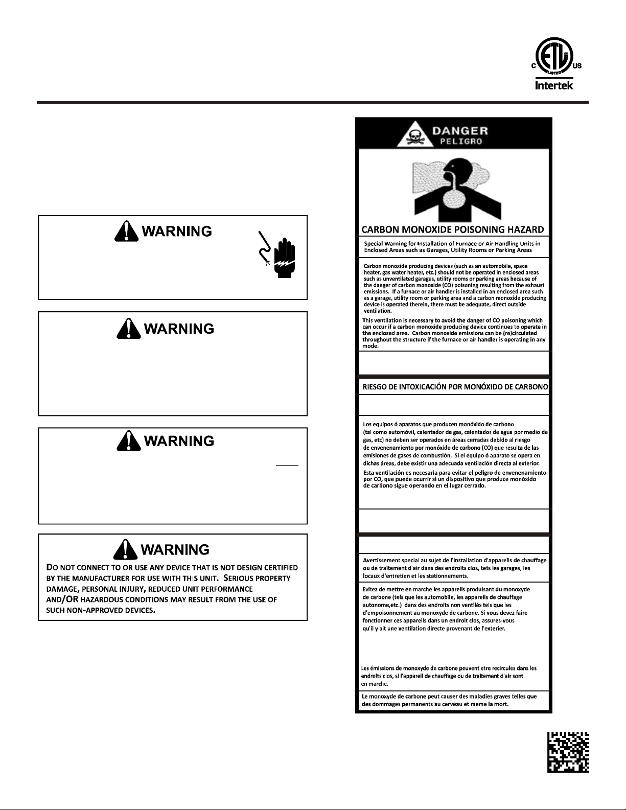
CO can cause serious illness including permanent brain
damage or death.
Advertencia especial para la instalación de calentadores ó manejadoras
de aire en áreas cerradas como estacionamientos ó cuartos de servicio.
Las emisiones de monóxido de carbono pueden circular a través
del aparato cuando se o pera en cualquier modo.
El monóxido de carbono pu ede causar enfe rmedades seve ras
como da ño cerebral per manente ó m uerte.
RISQU E D ' EMPOISONNEMENT AU
MONOXYDE DE CARBONE
B10259-216
B10259-216
IO-416E
12/2015
Cett e ven tilation est néc e ss a ir e po ur évi ter le danger d'in t o xi c a t i o n
au CO pouvant surv en i r si un app ar eil pro dui s ant du mo noxyde
de carbone con tin ue de fonctionne r au sein de la zon e con finé e.
B10259-216
Page 2
CAUTION
H
AVE YOUR CONTRACTOR IDENTIFY ALL THE VARIOUS CUTOFF SWITCHES
AND
DEVICES THAT SERVICE THIS UNIT
THAT
WILL CUT OFF ENERGY TO THE HEATING SYSTEM IN THE EVENT OF
OVERHEATING
.
SHIPPING INSPECTION
Upon receiving the product, inspect it for damage from shipment.
Shipping damage, and subsequent investigation is the responsibility of the carrier. Verify the model number, specifications,
electrical characteristics, and accessories are correct prior to
installation. The distributor or manufacturer will not accept claims
from dealers for transportation damage or installation of incorrectly shipped units.
CODES & REGULATIONS
This product is designed and manufactured to comply with national codes. Installation in accordance with such codes and/or
prevailing local codes/regulations is the responsibility of the installer. The manufacturer assumes no responsibility for equipment installed in violation of any codes or regulations.
The United States Environmental Protection Agency (EPA) has issued various regulations regarding the introduction and disposal
of refrigerants. Failure to follow these regulations may harm the
environment and can lead to the imposition of substantial fines.
These regulations may vary by jurisdiction. A certified technician
must perform the installation and service of this product. Should
you have any questions please contact the local office of the EPA.
REPLACEMENT PARTS
When reporting shortages or damages, or ordering repair parts,
give the complete product model and serial numbers as stamped
on the product. Replacement parts for this product are available
through your contractor or local distributor. For the location of
your nearest distributor consult the white business pages, the
yellow page section of the local telephone book or contact:
CONSUMER AFFAIRS
GOODMAN MANUFACTURING COMPANY, L.P.
7401 SECURITY WAY
HOUSTON, TEXAS 77040
(877) 254-4729
. K
NOW WHERE THE SWITCH IS
This ceiling mount air handler is available in cooling capacities
of 1.5, 2 and 2.5 nominal tons of cooling with a PSC motor (ACNF18,
ACNF24 and ACNF30) and 2 and 2.5 nominal tons of cooing with a
constant torque (EEM) motor (ACNF25 and ACNF31). Electric heat
models are available in capacities of 0, 5, 6, 8 and 10 kW.
The unit is designed to be installed in a horizontal position above
a dropped ceiling. Do NOT install this unit outside the structure.
These models are designed for INDOOR USE ONLY.
PRE-INSTALLATION INSTRUCTIONS
Carefully read all instructions for the installation prior to installing product. Make sure each step or procedure is understood and
any special considerations are taken into account before starting
installation. Assemble all tools, hardware and supplies needed
to complete the installation. Some items may need to be purchased
locally. Make sure everything needed to install the product is on
hand before starting.
Before attempting any installation, the following points should
be considered:
• Structural strength of supporting members
• Clearances and provision for servicing
• Power supply and wiring
• Air duct connections
• Drain facilities and connections
Installation Clearances
Place this unit as close to the space to be air conditioned as
possible. These units are U.L. listed for installations with zero
clearance to combustible materials. If this unit is installed in a
removable ceiling panel, ensure adequate space is available for
servicing. Run ducts as direct as possible to supply and return
outlets. Use non-flammable weatherproof flexible connectors on
both supply and return connections at unit to reduce noise transmission.
Ducting
Duct work should be fabricated by the installing contractor in
accordance with local codes. Use industry manuals such as such
as NESCA (National Environmental Systems Contractors Association, 1501 Wilson Blvd., Arlington, Virginia 22209) as a guide
when sizing and designing the duct system.
To ensure correct system performance, the ductwork is to be sized
to accommodate 375-425 CFM per ton of cooling with the static
pressure not to exceed 0.5” W.C. Inadequate ductwork that restricts airflow can result in improper performance and compressor or heater failure
APPLICATION INFORMATION
CAUTION
HEAT PUMP PREMATURE FAILURE NOTICE
UNNING THE UNIT WITHOUT
R
CAUSE PREMATURE UNIT FAILURE
ALL HEAT PUMP APPLICATIONS
ON
HPSK-1
. A HPSK-1
.
KIT INSTALLED ON HEAT PUMP
KIT MUST BE
INSTALLED
CAN
TO
PREVENT THE RISK OF PROPERTY DAMAGE, FIRE, CARBON MONOXIDE
POISONING
CONNECT DUCTWORK TO ANY HEAT PRODUCING DEVICE SUCH AS A
FIREPLACE INSERT OR STOVE
,
EXPLOSION, PERSONAL INJURY, OR DEATH, DO NOT
.
2
Page 3
Filters
Filters are not provided with unit, and must be supplied and installed in the return air system by the installer. A field installed
filter grille is recommended for easy and convenient access to the
filters for periodic inspection and cleaning. Filters must have
adequate face area for the rated air quantity of the unit. The minimum filter size is 20" x 20" x 1".
Condensate Drain Piping
The coil drain pan has a primary and a secondary drain with 3/4"
NPT female connections. The connectors required are 3/4" NPT
male, either PVC or metal pipe, and should be hand tightened to a
torque of approximately 37 in-lbs. to prevent damage to the drain
pan connection. An insertion depth between .355 to .485 inches
(3-5 turns) should be expected at this torque. Use the female (3/4
NPT) threaded fitting that protrudes outside of the enclosure for
external connections.
1. Ensure drain pan hole is NOT obstructed.
2. To prevent potential sweating and dripping on to finished
space, it may be necessary to insulate the condensate drain
line located inside the building. Use Armaflex® or similar
material.
A Secondary Condensate Drain Connection has been provided for
areas where the building codes require it. Pitch the drain line 1/
4" per foot to provide free drainage. Insulate drain lines located
inside the building to prevent sweating. Install a condensate trap
to ensure proper drainage. If the secondary drain line is required,
run the line separately from the primary drain and end it where it
can be easily seen.
NOTE: Water coming from this line means the coil primary drain
is plugged and needs clearing.
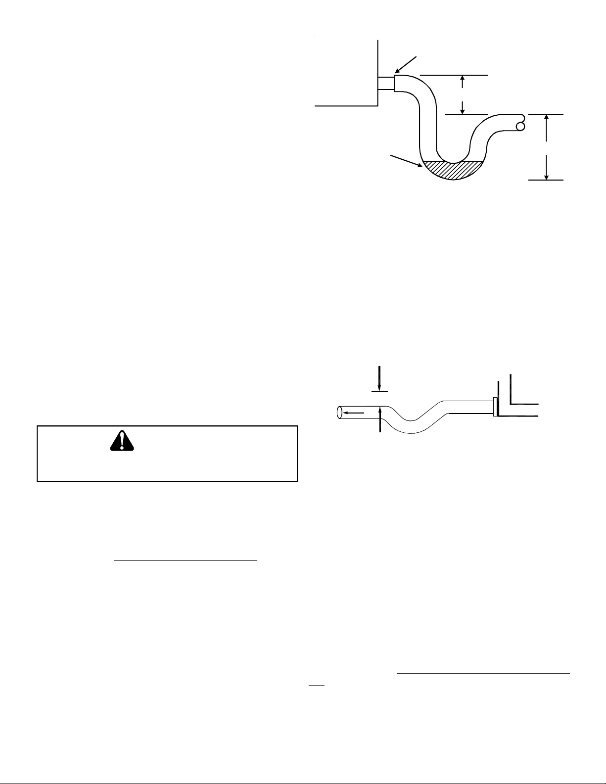
Drain
Connection
2" MIN.
Unit
POSITIVE LIQUID SEAL
REQUIRED AT TRAP
Figure 1
3" MIN.
The depth of a running trap (Figure 2) should be either 1" or a
depth that permits unrestricted condensate drainage without
excessive air discharge.
Field experience has shown condensate drain traps with an open
vertical Tee between the air handler and the condensate drain
trap can improve condensate drainage in some applications, but
may cause excessive air discharge out of the open Tee. We do not
prohibit this type of drain but we also do not recommend it due to
the resulting air leakage. Regardless of the condensate drain design
used, it is the installer’s responsibility to ensure the condensate
drain system is of sufficient design to ensure proper condensate
removal from the coil drain pan.
CAUTION
IF
SECONDARY DRAIN IS NOT INSTALLED, THE SECONDARY ACCESS
BE
MUST
PLUGGED
The installation must include a “P” style trap that is located as
close as is practical to the evaporator coil. See Figure 1 for details
of a typical condensate line “P” trap.
NOTE: Trapped lines are required by many local codes. In the
absence of any prevailing local codes, please refer to the requirements listed in the Uniform Mechanical Building Code.
A drain trap in a draw-through application prevents air from
being drawn back through the drain line during fan operation
thus preventing condensate from draining, and if connected to a
sewer line to prevent sewer gases from being drawn into the airstream during blower operation. In a blow-through application
the drain trap prevents conditioned air from escaping. It is permissible in this application to use a shallow trap design sometimes referred to as a running trap.
.
Figure 2
When coils are installed above ceilings, or in other locations
where damage from condensate overflow may occur, it is MAN-
DATORY to install a field fabricated auxiliary drain pan under the
coil cabinet enclosure. Drain lines from the auxiliary pan must be
installed and terminated so that the homeowner can see water
discharges. A primary condensate drain connection is located in
the drain pan on the bottom of the coil / enclosure assembly. The
female (3/4 fpt) threaded fitting that protrudes outside of the enclosure is used for external connections.
NOTE: Wire size based on 60°C rated wire insulation and 30°C
Ambient Temp. (86°F).
For branch circuit wiring (main power supply to unit disconnect),
determine the minimum wire size for the length of run from Table
1 using the circuit ampacity found on the unit rating plate. From
the unit disconnect to unit, the smallest wire size allowable in
Table 1 may be used, as long as the disconnect is in sight of the
unit.
3
Page 4

B RANCH CIRCUIT COPPER WIRE SIZE
(Base on 1% Voltage Drop)
64443322
200
SUPPLY WIRE 150
TW (60C) 100
LEN GTH - FEET 75
86644433
108866644
1210886644
14 12 18 10 8 8 6 6
50
15 20 25 30 35 40 45 50
BRANCH CI RCU IT AMPACITY
Note: Wiring for u nit onl y, no heat kit installed.
Table 1
For more than three conductors in a raceway or cable, see the
N.E.C. for derating the ampacity of each conductor.
LAYOUT FOR CEILING MOUNT AIR HANDLERS
NOTE: The location of the unit is based on thorough consideration
of the PRE-INSTALLATION CHECK POINTS.
1. Before locating the unit on the dropped ceiling, ensure the
strength of the ceiling and beams is adequate to support the
weight involved. This is an important step and the installers
responsibility. See the table below for approximate weight
of unit.
MODEL WEI GHT (lb.)
1.5 TON 5 7
2 TON 64
2.5 TON 6 8
Table 2
2. Mount the unit in a horizontal position above a dropped
ceiling of adequate strength. Refer to Figure 3. Refer to
Figure 4 for proper mounting methods.
Figure 4
3. The location of the unit should provide proper access for
inspection and servicing.
MODELABCD
1.5 TON 37 1/4 37 11/16 30 6 1/2
2 TON 43 1/4 40 11/16 36 6 1/2
2.5 TON 49 1/4 46 11/16 42 6 1/2
Table 3
TO DRAIN
Figure 3
DROP CEILING
PLENUM
OUTLET DUCT
GRILL FOR RETURN AIR
AND SERVICE
4
Page 5

4 3/8
A
B
IMPORTANT NOTE: Torch heat required to braze tubes of various
sizes is proportional to the size of the tube. Tubes of smaller size
require less heat to bring the tube to brazing temperature before
adding brazing alloy. Applying too much heat to any tube can melt
the tube. Service personnel must use the appropriate heat level for
the size of the tube being brazed.
NOTE: The use of a heat shield when brazing is recommended to
TOP VI EW
5
C
11 3/8
2 ½
avoid burning the serial plate or the finish on the unit. Heat trap
or wet rags should be used to protect heat sensitive components
such as service valves and TXV valves.
CAUTION
TO
PREVENT FEEDER TUBE DAMAGE, HOLD THE DISTRIBUTOR BODY WITH
A
3/4"
OPEN END WRENCH WHEN REMOVING OR REPLACING THE
13/16"
FLARE NUT
.
1. Remove the valve core to allow high pressure tracer gas to
escape. No gas indicates a possible leak.
2. Remove the 13/16" flare nut and tailpiece.
3. Unsweat the access fitting on the tailpiece
21
LIQUID LINE
¾
10
SUCTION LINE
CONTROL BOX
THIS END: LO W VOLTAGE WIRING
OPPOSITE END: SUPPLY VOLTAGE WIRING
D
1
Figure 5
SPECIAL INSTRUCTIONS
This airhandler comes equipped with an evaporator coil with a
check style flowrator assembly, an indoor blower and all necessary internal electrical wiring. For most installations with matching applications, no change to the flowrator orifice is required.
However, in mix-matched applications, a flowrator change may
be required. See the piston kit chart or consult your local distributor for details regarding mix-matched orifice sizing. If the mixmatch application requires a different piston size, change the
piston in the distributor on the indoor coil before installing the
coil and follow the procedure shown below.
4. Remove the check piston to verify it is correct and then replace the piston. See piston kit chart in instructions.
5. Unsweat the cap on the suction line.
6. Slide the 13/16" flare nut over the tailpiece.
7. Braze tailpiece to the lineset liquid tube.
8. Insert the suction line into the connection, slide the insulation at least 18" away from the braze joint. Braze suction
line.
9. AFTER THE TAILPIECE HAS COOLED, confirm position of the
white Teflon® seal and hand tighten the 13/16" flare nut.
10. Torque the 13/16" flare nut to 7-25 ft-lbs. or tighten 1/6 of a
turn. Do not overtighten.
CAUTION
E
XCESSIVE TORQUE CAN CAUSE ORIFICES TO STICK
SETTINGS WHEN TIGHTENING ORIFICES
TORQUE
11. Replace suction line insulation.
12. After installation, evacuation and charging of the low side
is complete, check fittings for leaks.
NOTE: With the piston in the distributor, the seal end should
point inside the distributor body and should not be seen when
looking into the end of distributor. Make sure the piston is free to
rotate, and move up and down in the distributor body.
.
. USE
THE PROPER
THE
EVAPORATOR COIL IS SHIPPED FROM THE FACTORY WITH
APPROXIMATELY
RELIEVING
200 PSI
PRESSURE
TRACER GAS CHARGE
.
. USE
CAUTION WHEN
5
Page 6

ELECTRICAL CONNECTIONS
BLUE
24 V CONNECTIONS
HIGH VOLTAGE!
D
ISCONNECT
POWER SOURCES MAY BE PRESENT
CAUSE PROPERTY DAMAGE, PERSONAL INJURY OR DEATH DUE
TO ELECTRIC SHOCK
AND ALL LOCAL CODES
CEC
EQUIPMENT PERFORMANCE, EQUIPMENT DAMAGE OR
POOR
FIRE
.
ALL
POWER BEFORE SERVICING
. W
IRING MUST CONFORM WITH
. U
NDERSIZED WIRES COULD CAUSE
. M
. F
AILURE TO DO SO MAY
ULTIPLE
NEC OR
Determine the availability of sufficient power to operate the unit.
The voltage at the power supply must correspond to the unit RATED
VOLTAGE REQUIREMENT.
Determine wire sizes from the unit nameplate ampacity and in
accordance with the National Electrical Code. Wiring should never
be sized smaller than is recommended by either of these two
sources.
The unit must be permanently grounded in accordance with local
codes, or in the absence of local codes, with the N.E.C. ANSI/NFPA
NO. 70-1987 or latest edition in the U.S.A.
Internal Wiring
A diagram of the internal wiring of this unit is located under the
electrical box cover. If any of the original wire as supplied with
the appliance must be replaced, the wire gauge and insulation
must be same as original wiring.
Transformer is factory wired for 230 volts on 208/ 230 volt models. See wiring diagram for 208 volt wiring. For 208V operation,
move the red wire lead from 240V to 208V tap.
MODEL
ALL MODELS 0.2
THERMOSTAT HEAT
ANTICIPATOR SETTING
CEILING MOUNT UNIT
B
R
HEAT PUMP
R
W
2
O
Y
C
YELLO W
RY
TO CONDENSING UNIT
G
W
THERMOSTAT
Figure 6
Br G
W
I
* W
* W
C.R.I.
24
5
13
* Y
6
* BI
Table 4
Make the following high and low voltage connections at either
location to wire units.
High Voltage Wiring
This unit is designed for Single phase 208/230 Volt only. Connect
the two leads to terminals L1 and L2 on the disconnect in the
electrical control section, using wire sizes specified in Table 1.
Low Voltage Wiring
For ACNF18, ACNF24 and ACNF30 models, refer to Figure 6 for
cooling unit with electric heat and refer to Figure 7 for heat pump
with electric heat.
NOTE: HPSK-01 Heat Pump Shut-Off Relay Kit (C.R.I.) must be used
when ACNF with electric heat installed with heat pump.
R
*WIRES SUPPLIES WITH HPSK KIT
YEG
O
THERMOSTAT
W
C
2
Note: in case of heat pump failure, switch to "E" on Thermostat
for emergency heat. See note under Low Voltage Wiring
Figure 7
Connect low voltage wires from the thermostat to the corresponding wires in the Ceiling Mount unit and outdoor unit using No. 18
AWG wires as follows:
LEAD THERMOSTAT NOTES
RED R (24V) -
GREEN G (FAN) -
-Y
WHITE W -
BLUE -
BROWN E
Table 5
TO CONDENSING UNIT
24V CONNECTIONS
TO CONDENSING UNIT
24V CONNECTIONS
TO BE USED FOR
EMERGENCY HEAT ONLY
6
Page 7

CONSTANT TORQUE (EEM) MOTORS
ACNF25 and ACNF31 models utilize constant torque (EEM) motors.
These motors come with a separate control box which is mounted
on the side of the unit as shown in Figure 8. The harness from the
motor is inserted into the control box which has another harness
leading into the control panel of the unit.
Control Box
Figure 8
The high voltage wiring is the same as the other ACNF models.
The low voltage wiring connections for the ACNF25 and ACNF31
models are shown in Figure 9. The wire from the motor, T2 (purple,)
T3 (pink) or T4 (yellow), connects to “Y” from the thermostat/condenser depending on the application. The rest of the connections
are similar to the other ACNF models.
Thermostat
Y R G W
#18 Gauge
24 VAC
C
Y
R
#18 Gauge
24 VAC
C Y
Condensing Unit
CONFIRM SPEED TAP SELECTED (T2, T3, OR T4)
IS APPROP RIATE FOR THE APPLICATION BASED ON THIS TABLE.
WIRE COLOR
PURPLE
PINK
YELLOW
BTU
18000
24000
HIGH CFM OPTION
Figure 9
G
Note: Connect T2,T3 or T4 to the Y
terminal to the outdoor unit.
h
W
T1 T5
Air Han dler
MAINTENANCE
Room Thermostat
The room thermostat controls the operation of your heating and/
or cooling unit. It senses the indoor temperature and signals the
equipment to start or stop maintaining the temperature you have
selected for your comfort. The room thermostat should be in a
central, draft free inside wall location for best operation. Do not
place any heat producing apparatus such as lights, radio, etc.,
near the thermostat as this will cause erratic operation of the
comfort system.
Air Filter(s)
All central air moving comfort systems must include air filter(s).
Locate these filters in either the equipment or return air duct system upstream of the equipment. The filter(s) removes dust and
debris from the air thus helping to keep your conditioned space
clean. More important, the filter keeps dust and debris from collecting on heat transfer surfaces thus maintaining optimum equipment efficiency and performance. Inspect and clean or replace
filters every month. This routine maintenance procedure will pay
big dividends in reduced operating cost and reduced service expense. Never operate comfort equipment without filter(s).
Fuses and/or Circuit breakers
This comfort equipment should be connected to the building electric service in accordance with local and National Electric codes.
This electrical connection will include over current protection in
the form of fuses or circuit breakers. Have your contractor identify the circuits and the location of over current protection so that
you may be in a position to make inspections or replacements in
the event the equipment fails to operate. Keep replacement fuses
of the proper size on hand.
Periodic Checkup and Service
This unit is designed to provide many years of dependable, troublefree comfort when properly maintained. Proper maintenance will
consist of annual checkups and cleaning of the internal electrical
and heat transfer components by a qualified service technician.
Failure to provide periodic checkup and cleaning can result in
excessive operating cost and/or equipment malfunction.
Aluminum Indoor Coil Cleaning (Qualified Servicer Only)
This unit is equipped with an aluminum tube evaporator coil. The
safest way to clean the evaporator coil is to simply flush the coil
with water. This cleaning practice remains as the recommended
cleaning method for both copper tube and aluminum tube residential cooling coils.
An alternate cleaning method is to use one of the products listed
in the technical publication TP-109 (shipped in the literature bag
with the unit) to clean the coils. The cleaners listed are the only
agents deemed safe and approved for use to clean round tube
aluminum coils. TP-109 is available on the web site in Partner
Link > Service Toolkit.
NOTE: Ensure coils are rinsed well after use of any chemical cleaners.
7
Page 8

BLOWER CHART FOR ACNF
Model
ACNF180XXX
ACNF240XXX
ACNF300XXX
ACNF25XXXX
Motor
External Static Pressure, (CFM)
Speed
0.1" 0.2" 0.3" 0.4" 0.5"
High 710 660 590 515 435
Low 650 595 540 480 390
High 955 880 820 740 675
Low 885 840 775 725 620
High 1,075 1,005 920 820 730
Low 945 890 835 760 650
T5 969 912 854 798 778
T4 969 912 854 798 778
T3 802 776 690 641 584
T2 680 610 550 484 431
T1 680 610 550 484 431
T5 999 928 868 824 764
T4 999 928 868 824 764
Airflow rate d elivered against
ACNF31XXXX
T3 871 798 750 687 614
T2 763 695 625 548 478
T1 763 695 625 548 478
NOTE: Airflow data for 240 Vac with dry coil and no filter in place.
NOTE: SPECIFICATIONS AND PERFORMANCE DATA LISTED HEREIN ARE SUBJECT TO CHANGE WITHOUT NOTICE
Quality Makes the Difference!
All of our systems are designed and manufactured with the same high quality standards regardless of size or efficiency. We have designed these
units to significantly reduce the most frequent causes of product failure. They are simple to service and forgiving to operate. We use quality
materials and components. Finally, every unit is run tested before it leaves the factory. That’s why we know. . .There’s No Better Quality.
Visit our website at www.daikincomfort.com, www.goodmanmfg.com or www.amana-hac.com for information on:
• Products
• Warranties
• Customer Services
• Parts
• Contractor Program and Training
• Financing Options
5151 San Felipe, Suite 500, Houston, TX 77056
© 2011 - 2015
is a registered trademark of Maytag Corporation or its related companies and is used under license. All rights reserved.
Goodman Manufacturing Company, L.P.
8
 Loading...