

Page 1
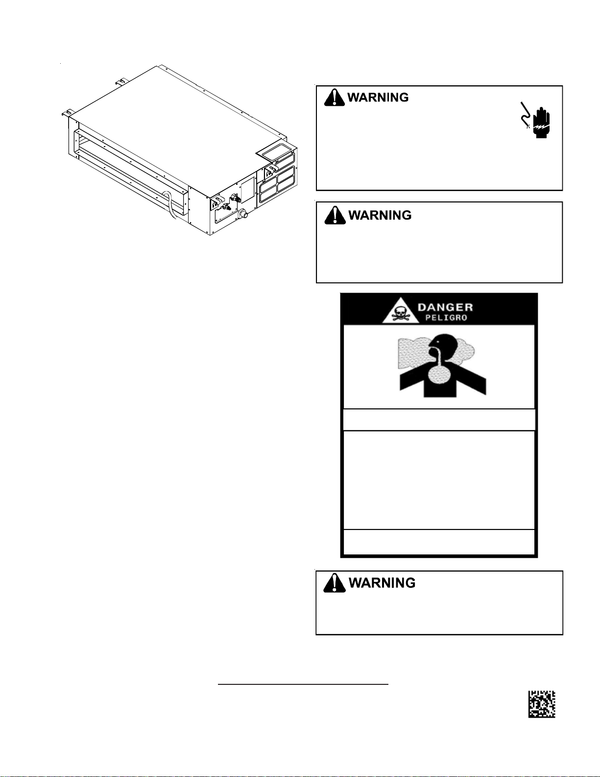
ACNF CEILING MOUNT AIR HANDLER
INSTALLATION INSTRUCTIONS
SHIPPING INSTRUCTIONS ..................................................... 2
APPLICATION INFORMATION ................................................... 2
P
RE-INSTALLATION CONSIDERATIONS ...................................... 2
INSTALLATION ORDER .......................................................... 3
LAYOUT FOR CEILING MOUNT AIR HANDLERS ......................... 3
OUTDOOR UNIT INSTALLATION ............................................... 9
INSTALLING THE CONNECTING PIPE ...................................... 10
REFRIGERANT PIPE CONNECTION ........................................ 11
CONNECTING THE AIR HANDLER TO THE OUTDOOR UNIT ......... 12
CONNECTING THE DRAIN PIPE - INDOOR UNIT ....................... 12
UNITS WITH FRESH AIR DUCT INSTALLATION ......................... 14
MOTOR AND DRAIN PUMP MAINTENANCE ............................. 14
ELECTRICAL WIRING ........................................................ 14
TESTING THE UNIT’S OPERATION ......................................... 15
WIRING DIAGRAMS ........................................................... 18
Important Safety Instructions
The following symbols and labels are used throughout this
manual to indicate immediate or potential safety hazards. It
is the owner’s and installer’s responsibility to read and comply with all safety information and instructions accompanying these symbols. Failure to heed safety information increases the risk of personal injury, property damage, and/or
product damage.
HIGH VOLT AGE!
D
ISCONNECT
INSTALLING
MAY
BE
DAMAGE
IRING MUST CONFORM WITH
W
CODES
PERFORMANCE
G
OODMAN WILL NOT BE RESPONSIBLE FOR ANY INJURY OR
PROPERTY
SERVICE
OWN
PERSONAL
ALL
POWER BEFORE SERVICING OR
THIS UNIT
PRESENT
,
PERSONAL INJURY OR DEATH DUE TO ELECTRIC SHOCK
. U
NDERSIZED WIRES COULD CAUSE POOR EQUIPMENT
DAMAGE ARISING FROM IMPROPER SERVICE OR
PROCEDURES
PRODUCT, YOU ASSUME RESPONSIBILITY FOR ANY
INJURY OR PROPERTY DAMAGE WHICH MAY RESULT
. M
ULTIPLE POWER SOURCES
. F
AILURE TO DO SO MAY CAUSE PROPERTY
NEC OR CEC
,
EQUIPMENT DAMAGE OR FIRE
. IF
YOU PERFORM SERVICE ON YOUR
AND ALL LOCAL
.
CARBON MONOXIDE POISONING HAZARD
Special Warning for Installation of Furnace or Air Handling Units in
Enclosed Areas such as Garages, Utility Rooms or Parking Areas
Carbon monoxide producing devices (such as an automobile, space
heater, gas water heater, etc.) should not be operated in enclosed areas
such as unventilated garages, utility rooms or parking areas because of
the danger of carbon monoxide (CO) poisoning resulting from the exhaust
emissions. If a furnace or air handler is installed in an enclosed area such
as a garage, utility room or parking area and a carbon monox i de produc ing
device is operated therein, there must be adequate, direct outside
ventilation.
This ventilation is necessary to avoid the danger of CO poisoning which
can occur if a carbon monoxide producing device continues to operate in
the enclosed area. Carbon monoxide emissions can be (re)circulated
throughout the structur e if the furnace or air handle r is operating in any
mode.
CO can cause serious illness including permanent brain damage or death.
B10259-216
-
.
.
Codes & Regulations
This product is designed and manufactured to comply with
local, national and international laws, codes and regulations.
Installation in accordance with such codes and/or prevailing
local codes/regulations is the responsibility of the installer.
The manufacturer assumes no responsibility for equipment
installed in violation of any codes or regulations.
© 2011 Goodman Manufacturing Company, L.P.
IO- 422
10/2011
5151 San Felipe, Suite 500, Houston, TX 77056
www.goodmanmfg.com -or- www.amana-hac.com
TO
PREVENT THE RISK OF PROPERTY DAMAGE, PERSONAL INJURY
OR DEATH, DO NOT STORE COMBUSTIBLE MATERIALS OR USE
GASOLINE
VICINITY
OR
OTHER FLAMMABLE LIQUIDS OR VAPORS IN THE
OF
THS APPLIANCE
.
1
,
Page 2
WARNING
Do not connect to or use any device that is not design
certified by Goodman for use with this unit. Serious
property damage, personal injury, reduced unit
perform ance and/O R haza rdou s cond itio ns m ay resu lt
from the use of such non-approved devices.
CAUTION
Have your contractor identify all the various cutoff switches
and devices that service this unit. Know where the switch is
that will cut off energy to the heating system in the event of
overheating.
Special Notes for European Consumers:
Do not dispose of this product as unsorted municipal waste.
Collection of such waste for special treatment is necessary.
It is strictly prohibited to dispose of this unit in domestic
household waste. Disposal options:
1. Some municipalities have established collection systems
to collect electronic waste for disposal.
2. Your purchase point retailer (or manufacturer) may take
back the unit for disposal.
3. Used products contain valuable resources and can be
sold to scrap metal dealers.
Illegal disposal in forests and landscapes endanger your
health and the environment. Hazardous materials leak into
ground water.
SHIPPING INSPECTION
Upon receiving the product, inspect it for damage from shipment. Shipping damage, and subsequent investigation is the
responsibility of the carrier. Verify the model number, specifications, electrical characteristics, and accessories are correct prior to installation. The distributor or manufacturer will
not accept claims from dealers for transportation damage or
installation of incorrectly shipped units.
APPLICATION INFORMATION
This ceiling mount air handler is available in cooling capacities of 1.0, 1.5, 2, 2.5, 3.0, 3.5, 4.0 and 6.0 nominal tons of
cooling. Electric heat models are available in capacities of 0,
5, 6, 8 and 10 kW.
The unit is designed to be installed in a horizontal position
above a dropped ceiling. Do NOT install this unit outside
the structure. These models are designed for INDOOR
USE ONLY.
PRE-INSTALLATION CONSIDERATIONS
Carefully read all instructions for the installation prior to installing product. Make sure each step or procedure is understood and any special considerations are taken into account
before starting installation. Assemble all tools, hardware
and supplies needed to complete the installation. Some items
may need to be purchased locally. Make sure everything
needed to install the product is on hand before starting.
Before attempting any installation, the following points should
be considered:
• Structural strength of supporting members
• Clearances and provision for servicing
• Power supply and wiring - Routing of wires must be
arranged so the control board cover is fixed properly.
If not, a possibility of overheating, fire or electrical
shock may occur at the connection point of the terminal.
• Air duct connections - Ductwork should be fabricated
in accordance with local codes and sized to accommodate 375-425 CFM per ton of cooling with the static
pressure not to exceed 0.5” W.C. Inadequate ductwork
that restricts airflow can result in improper performance
and compressor or heater failure.
• Drain facilities and connections
• Installation of unit must be, at a minimum, of 91” (2.3m)
above the floor.
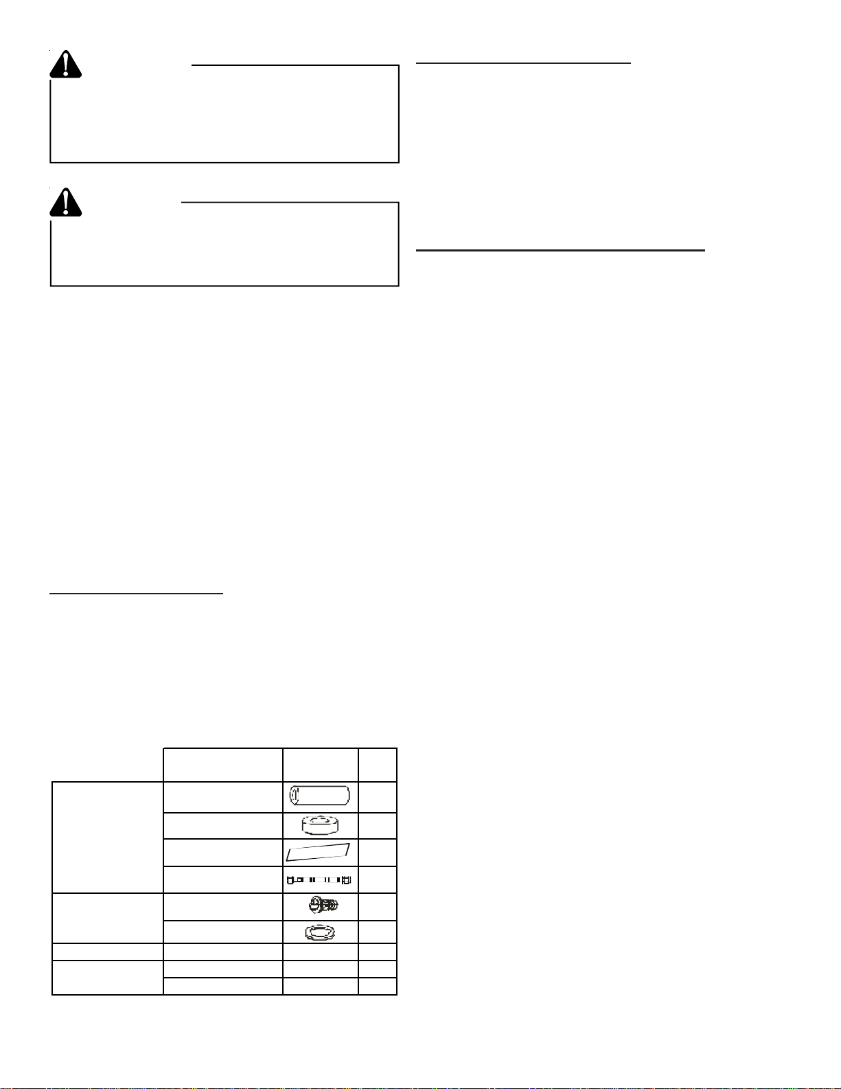
Tubes
&
Fittings
Drain Pipe
Fittings for
cooling/heating
Wire controller
Literature
* As applicable
Name Shape Qty.
Soundproof/
Insulation sheath
Binding Tape 1
Seal Sponge 1
*Orifice 1
Drain joint 1
Seal ring 1
Wire controller
Owner's Manual
Installation Manual
---
--- 1
--- 1
• Electrical installations must be in accordance with local national wiring standards, regulations and this installation instruction. An independent circuit and single
2
outlet must be used. If installed without the proper
electrical circuit capacity, or installed defectively, possibility of electrical shock or fire may occur.
• To ensure proper performance of unit, use the specified cable, and clamp the cable securely to prevent
disconnection as this will cause overheating or fire at
the connection.
• An all-pole disconnect switch, having a contact sepa-
1
ration of at least 3mm in all poles, should be connected in the fixed wiring.
2
Page 3
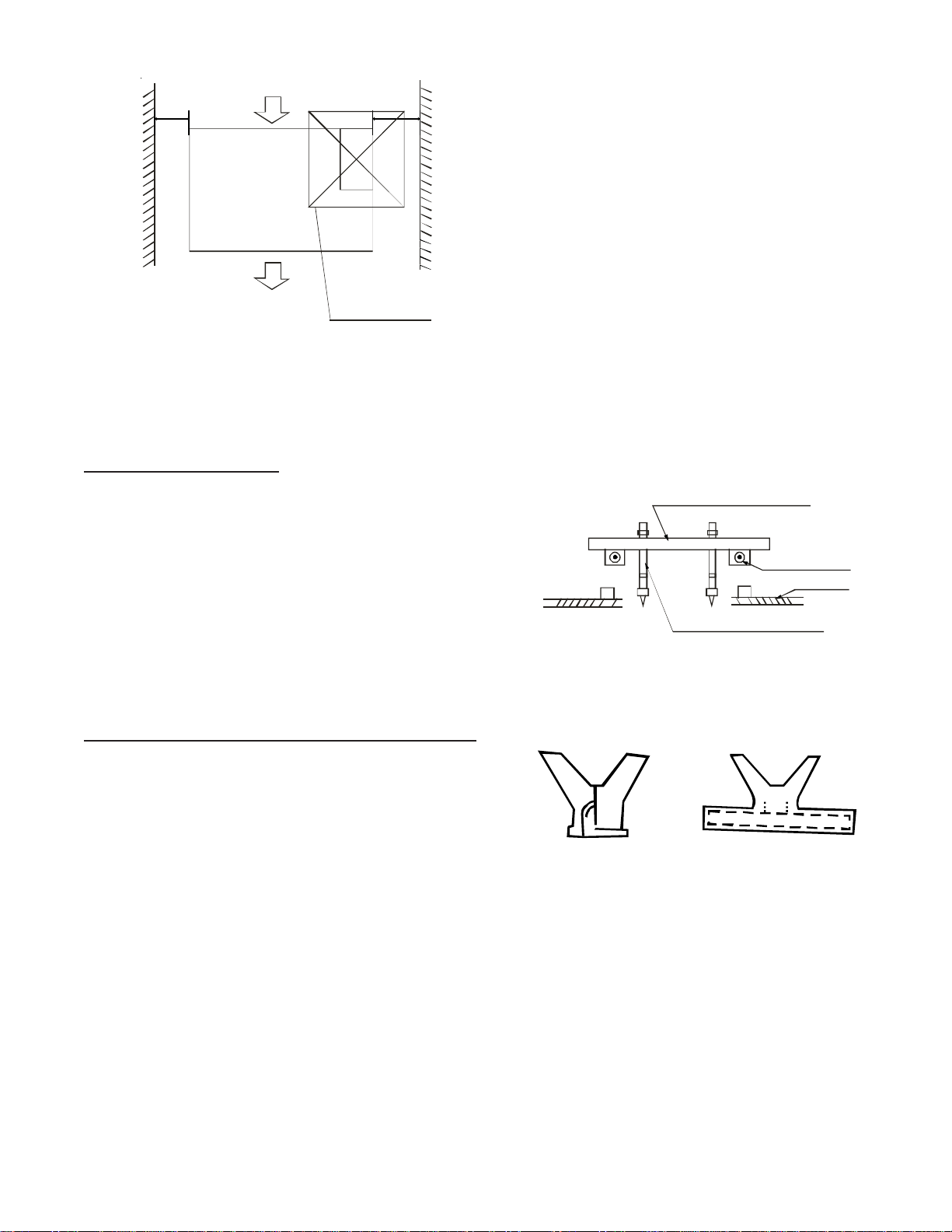
8” (200mm)
or more
12” (300mm)
or more
24” x 24”
(600mm x 600mm)
(Checking orifice)
3. The installation to ceilings varies with construction. Con-
sult construction personnel for the specific procedures.
4. Install pipes and lines in the ceiling after completion of
the installation of the ACNF air handler. The first consideration of installation is to determine the direction of
the pipes. When installing in a ceiling, position the refrigerant pipes, drain pipes, indoor and outdoor lines to
the connections before hanging the unit.
5. Install the hanging screw bolts.
6. After the selection of installation location, position the
refrigerant pipes, drain pipes, indoor and outdoor lines
to the connections before hanging the unit.
7. Attach the hanging screw bolts.
Figure 1 - Room clearances
NOTE: To prevent interference, keep indoor unit, outdoor
unit, power supply wiring and transmission wiring at
least 39” (1 meter) from televisions and radios.
INSTALLATION ORDER
Install your unit in the following order:
1. Select the mounting locations.
2. Install the indoor unit.
3. Instal the outdoor unit.
4. Install the connecting pipe
5. Connect the drain pipe.
6. Wiring.
7. Test operation.
LAYOUT FOR CEILING MOUNT AIR HANDLERS
NOTE: The location of the unit is based on thorough consid-
eration of the PRE-INSTALLATION CHECK POINTS below:
NOTE: The minimum drain tilt is at least 1/100.
Wooden construction
Put the square timber traversely over the roof beam, then
install the hanging screw bolts.
Timber over the beam
Roof Beam
Ceiling
Hanging Screw Bolts
Figure 2
New Concrete or Bricks
Embedding the screw bolts, Figure 3.
• Structural strength of supporting members
• Clearances and provision for servicing
• Power supply and wiring
• Air duct connections
• Drain facilities and connections
1. Before locating the unit on the dropped ceiling, ensure
the strength of the ceiling and beams is adequate to
support the weight involved. This is an important step
and the installers responsibility.
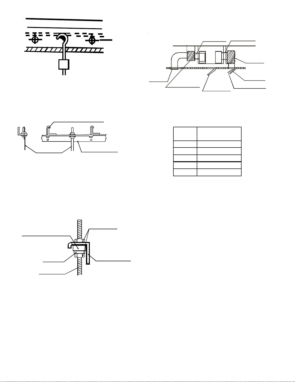
Installing the four (4) 3/8” (Ø 10) Hanging Screw Bolts
2. Mount the unit in a horizontal position above a dropped
ceiling of adequate strength with four 3/8” (Ø 10) hanging screw bolts. Refer to the following figures for distance between the screw bolts.
Blade Shape
Insertion
Slide
Insertion
Figure 3
Installation for Existing Concrete Bricks
Use embedding screw bolt, crock and stick harness as shown
in Figure 4.
3
Page 4
2. A dust filter is located on the indoor unit.
Recommended duct connections:
Steel Bar
Canvas tie-in
Canvas tie-in
Embedding screw bolt
(Pipe hanging & embedding screw bolt)
Figure 4
Steel Room Beam Structure
Install directly on the supporting angle steel. See Figure 5.
Hanging Screw Bolt
Hanging Bolts
Hanging Bolts
Supporting Angle Steel
Figure 5
Hanging the Indoor Unit
1. Place the indoor unit onto the hanging screw bolts with
block.
2. Using a level, position the unit to hang flat to prevent
leaks, Figure 6.
Isolation
booth
Air
outlet
Isolation
booth
Checking
orifice
Air inlet
Air dust filter
Figure 7
3. It is important to maintain the static pressure below to
alleviate excessive noise, blowing water or other abnormalities.
Model
(Kw)
12 0.16 (40)
18 0.28 (70)
24 0.28 (70)
30-36 0.32 (80)
42-60 0.40 (100)
Static Pressure
Inches H
0 (Pa)
2
NOTES:
1. The indoor unit should not bear the connecting duct’s
weight.
2. Use the fire retardant canvas tie-in to prevent vibrating.
Screw Nut
Shock-proof cushioningShock-proof cushioningShock-proof cushioning
Washer
Overhang
Hanging Screw Bolt
Figure 6
Installing the dust proof net and canvas air passage
1. Install the dust proof net according to the installation
manual.
2. Install the canvas air passage underneath the dust proof
net.
Duct Design
1. Air inlet/outlet ducts must be spaced to prevent air from
the outlet from entering the air inlet.
3. When connecting the ductwork, install in a location
where maintenance can be done easily.
4. The fan motor static pressure should correspond to the
external static pressure.
5. When installed in a noise-sensitive setting, install an
isolation booth and internal duct underlayer to help muffle
the duct noise. (Figure 7.)
4
Page 5
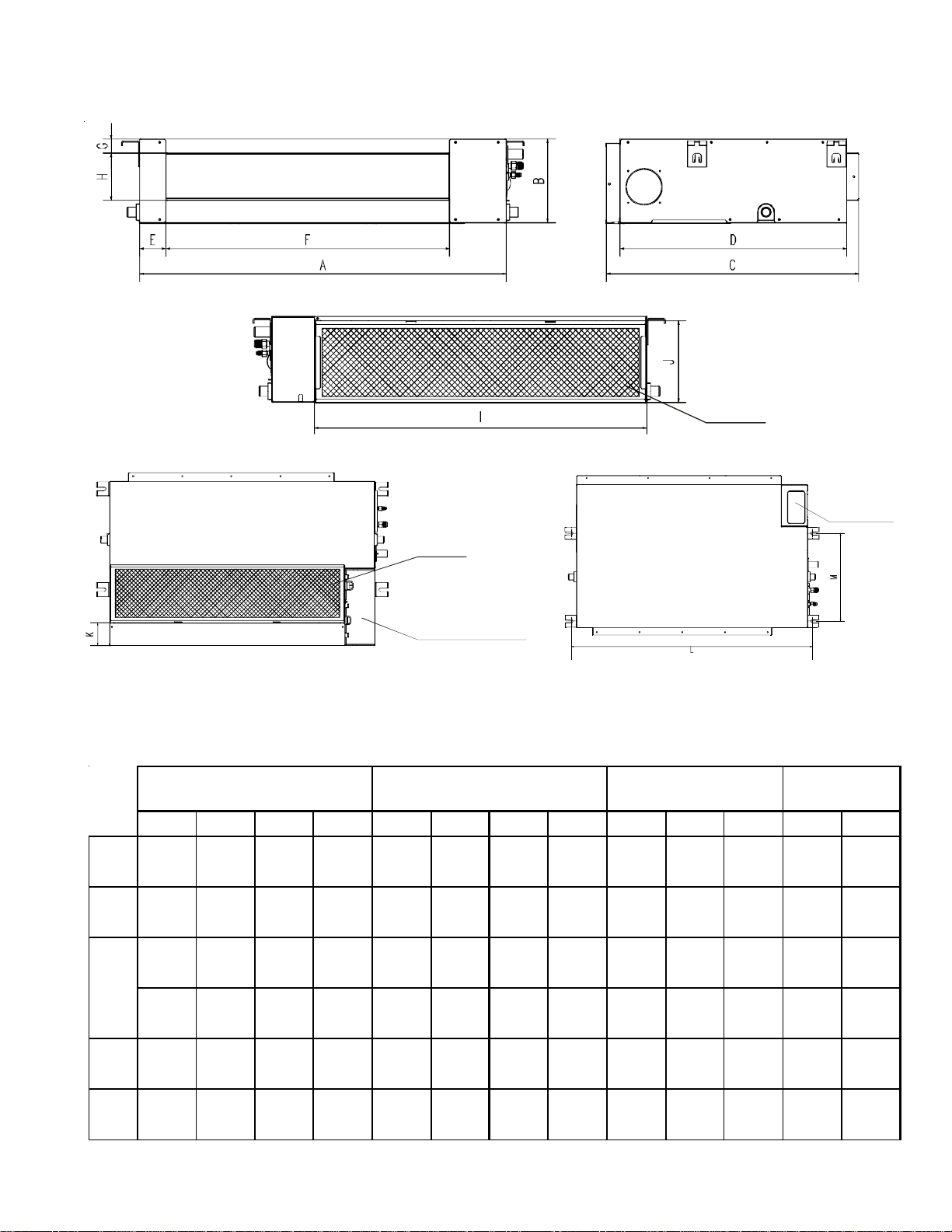
Positioning the ceiling hole, indoor unit and hanging screw bolts.
See table below for dimensions.
Air
filter
Air
filter
Electric
control
cabinet
12
12, 18
24
30-36
Electric
control cabinet
Figure 8
Outline dimemsion
ABCDE FGH I JKLM
27 1/2"
700mm8"210mm
36"
920mm8"210mm
45"
1140mm8"210mm
36"
920mm
45"
1140mm
10 1/2"
270mm
10 1/2"
270mm
25"
635mm
25"
635mm
25"
635mm
25"
635mm
30 1/2"
775mm
22 1/4"
570mm
22 1/4"
570mm
22 1/4"
570mm
22 1/4"
570mm
28"
710mm
2 1/2"
65mm
2 1/2"
65mm
2 1/2"
65mm
2 1/2"
65mm
2 1/2"
65mm
Air outlet
opening size
19 1/4"
493mm
28"
713mm
36 3/4"
933mm
28"
713mm
36 3/4"
933mm
1 1/4"
35mm
1 1/4"
35mm
1 1/4"
35mm
1 1/4"
35mm7"179mm
1 1/4"
35mm7"179mm
4 3/4"
119mm
4 3/4"
119mm
4 3/4"
119mm
23 1/4"
595mm8"200mm3"80mm
815mm8"200mm3"80mm
40 3/4"
1035mm8"200mm3"80mm
815mm
40 3/4"
1035mm
32"
32"
Air return
opening size
10"
260mm
10"
260mm
3/4"
20mm
3/4"
20mm
Size of
mounted lug
29"
740mm
37 3/4"
960mm
46 1/2"
1180mm
37 3/4"
960mm
46 1/2"
1180mm
13 3/4"
350mm
13 3/4"
350mm
13 3/4"
350mm
13 3/4"
350mm
19 1/4"
490mm
42-60
47"
1200mm
11 3/4"
300mm
34"
865mm
31 1/2"
800mm
31"
80mm
38"
968mm
1 1/2"
40mm8"204mm
5
43"
1094mm
11 1/4"
288mm
1 3/4"
45mm
48 3/4"
1240mm
19 3/4"
500mm
Page 6
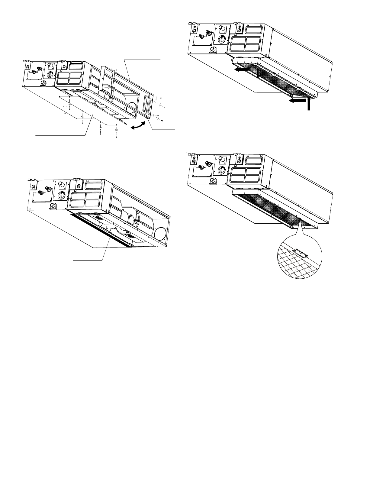
Adjusting the airflow direction
1. Remove the ventilation panel and flange; cut off the
staples at the side rail.
Air return flange
Ventilation panel
Figure 9
2. Attach the seal sponge as shown below. Change the
mounting positions of the air return panel and air return
flange.
Side rail
Figure 11
4. Insert the clips in the flange holes as shown in Figure
12.
Seal sponge
Figure 10
3. When installing the filter mesh, place the filter mesh in
the flange and push up to set it in place, as shown by
the arrows in the following Figure 11.
Figure 12
6
Page 7
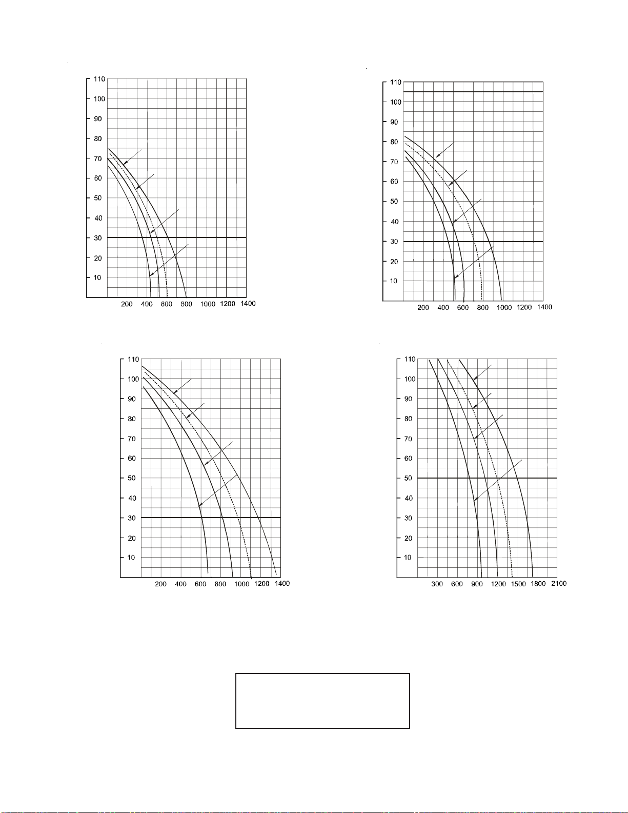
Fan Performance - Stactic Pressure Curve
(Pa)
Model 12
)
a
P
(
e
r
u
s
s
e
r
P
c
i
t
a
t
S
l
a
n
r
e
t
x
E
Super High Speed
High Speed (reserved)
Medium Speed
Low Speed
(Pa)
Air volume (m3/h)
(Pa)
Model 24
Super High Speed
(Pa)
Model 18
Super High Speed
High Speed (reserved)
Medium Speed
Low Speed
Air volume (m3/h)
Model 30
Super High Speed
)
a
P
(
e
r
u
s
s
e
r
P
c
i
t
a
t
S
l
a
n
r
e
t
x
E
Air volume (m3/h)
High Speed (reserved)
Medium Speed
Low Speed
Air volume (m3/h)
High Speed (reserved)
Medium Speed
Low Speed
NOTE:
1 m3/hr = 0.586 CFM
100 Pa = 0.4015 Inches of water
7
Page 8
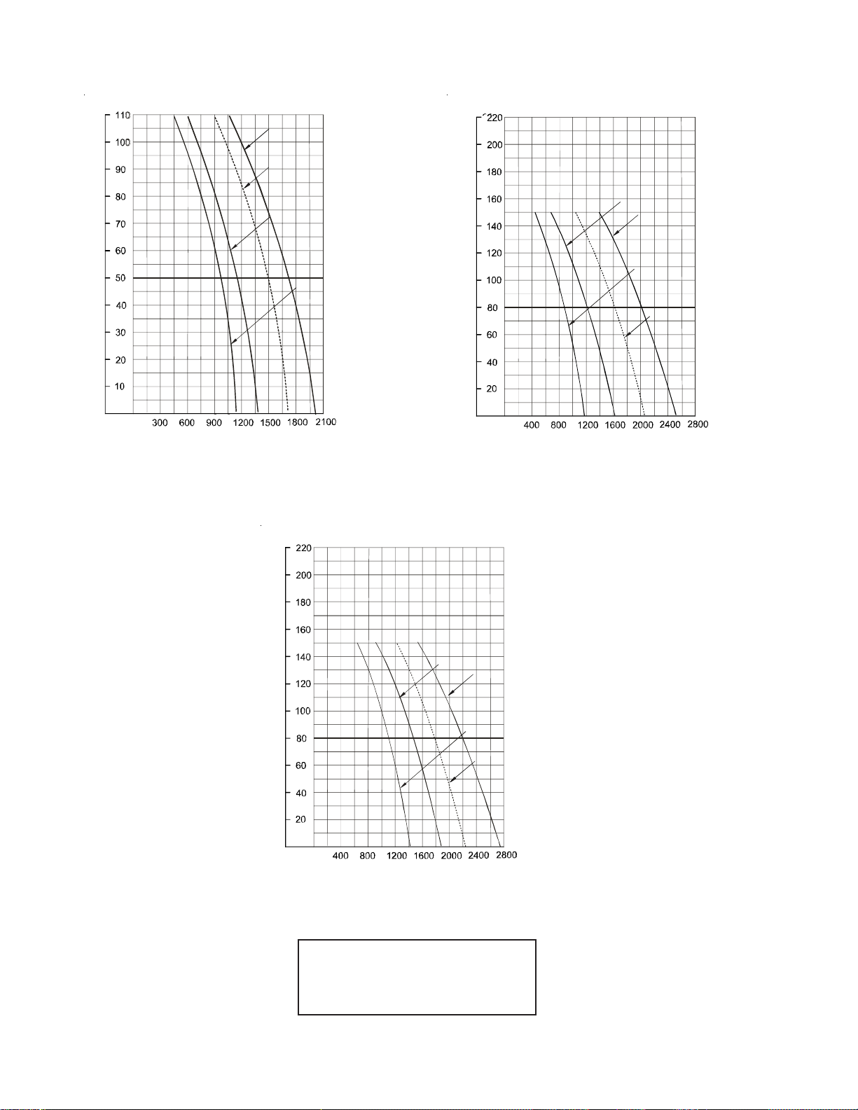
Fan Performance - Static Pressure Curve
(Pa)
Model 36
Super High Speed
)
a
P
(
e
r
u
s
s
e
r
P
c
i
t
a
t
S
l
a
n
r
e
t
x
E
High Speed (reserved)
Medium Speed
Low SpeedLow Speed
Air volume (m3/h)
(Pa)
Model 42-48
)
a
P
(
e
r
u
s
s
e
r
P
c
i
t
a
t
S
l
a
n
r
e
t
x
E
Medium Speed
Super High Speed
Low Speed
High Speed (reserved)
Air volume (m3/h)
(Pa)
Model 60
)
a
P
(
e
r
u
s
s
e
r
P
c
i
t
a
t
S
l
a
n
r
e
t
x
E
Medium Speed
Super High Speed
Low Speed
High Speed (reserved)
Air volume (m3/h)
NOTE:
1 m3/hr = 0.586 CFM
100 Pa = 0.4015 Inches of water
8
Page 9
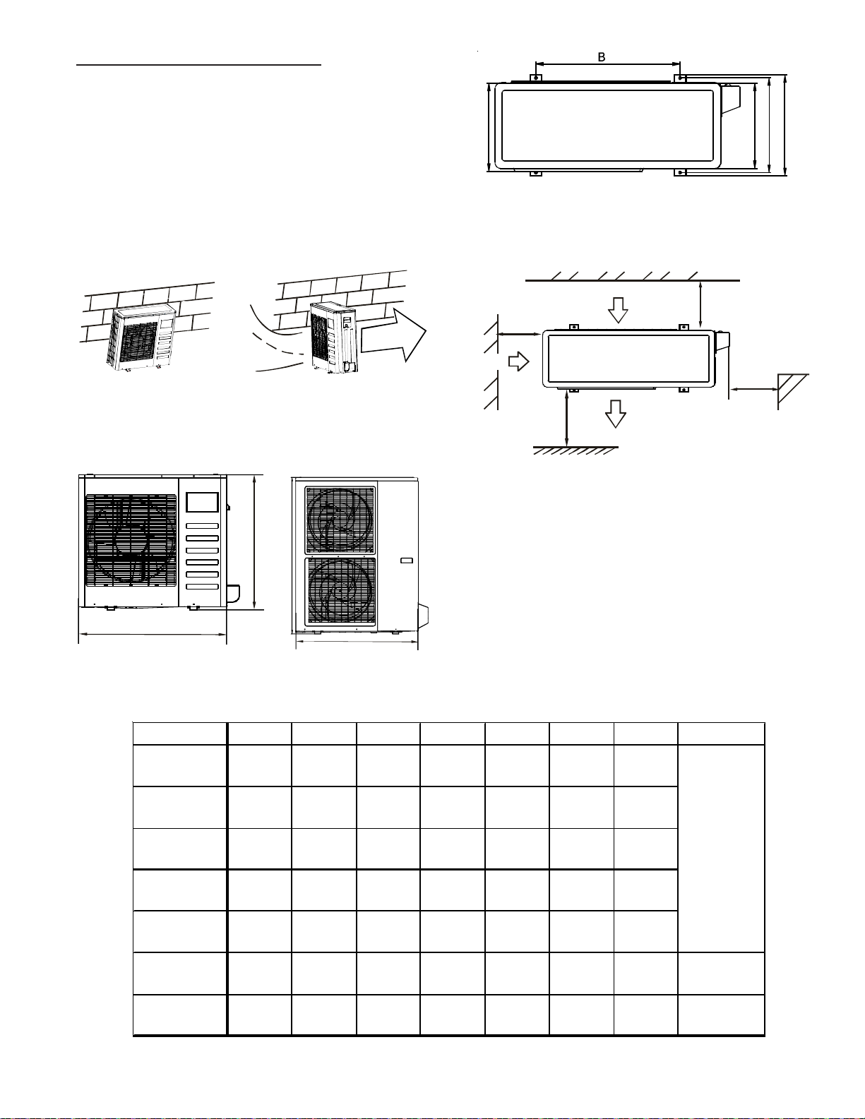
OUTDOOR UNIT INSTALLATION
The following are considerations before installing the outdoor unit.
• Install the outdoor unit on a rigid base to prevent noise
and vibration.
• Place the outdoor unit in such a manner to minimize
restriction of discharge air.
• Protect the unit from prevailing winds. To ensure the
unit operates correctly, place the unit lengthwise along
a wall or use a dust or shield plate.
S
T
R
O
N
G
W
I
N
D
Figure 13A
• Install in a place where the unit is easily accessible
for installation and maintenance.
Figure 13B
F
D
E
C
Figure 14C
• See Figure 15 for minimum distances to obstacles.
Two of the three must remain unobstructed.
Wall or obstacle
)
”
m
2
c
1
0
>
3
(
>24”
(60cm)
P
Air Inlet
>12”
(30cm)
N
Air Inlet
)
”
m
c
9
0
7
0
>
2
(
M
Air Outlet
Figure 15
Moving and Installation
Notes:
H
• The inlet of the unit should not be used as a “handle”
when moving the unit.
• Use caution when moving the unit with a sling, since
the center of gravity is not in the unit’s physical cen-
A
A
ter.
• The fan should not be touched with hands or any foreign objects.
Figure 14A Figure 14B
• Do not lean the unit more than 45° or lay it on its side.
ModelABC DEFHFigure Ref.
12,000
R-22 & R-410A
18,000
R-22 & R-410A
24,000
R-22 & R-410A
30,000/36,000
R-22 & R-410A
31"
780mm
30"
762mm
33"
842mm
39"
990mm
21 1/2"
548mm
21"
530mm
22"
560mm
24 1/5"
624mm
10 1/2"
266mm
11"
290mm
13"
335mm
14"
366mm
11 1/2"
300mm
12"
315mm
14"
360mm
15 1/2"
396mm
9 1/2"
241mm
10 1/2"
270mm
12"
312mm
13"
340mm
9 1/2"
250mm
11"
282mm
12 1/2"
324mm
13 3/4"
354mm
21 1/2"
547mm
23"
593mm
27"
695mm
38"
966mm
Figure 14A
48,000
R-22 Only
48,000
R-410A Only
60,000
R-22 & R-410A
39"
990mm
35"
900mm
35"
900mm
24 1/5"
624mm
23"
590mm
23"
590mm
14"
366mm
14 3/4"
378mm
14 3/4"
378mm
15 1/2"
396mm
15 1/2"
400mm
15 1/2"
400mm
9
13"
340mm
13"
330mm
13"
330mm
13 3/4"
354mm
13 1/4"
340mm
13 1/4"
340mm
38"
966mm
45 3/4"
1167m m
45 3/4"
1167m m
Figure 14B
Figure 14B
Page 10

• See Figure 16 for securing the outdoor unit horizon-
A
tally to a concrete foundation. Fasten the feet of the
outside unit securely with bolt to prevent movement of
the unit in adverse weather conditions, such as high
winds or earthquake.
”
½
m
c
3
0
2
6
>
ttach
with bolt
Figure 16
INSTALLING THE CONNECTING PIPE
The following chart lists the proper height drop between the
indoor unit and outdoor, the length of refrigerant pipe and the
number of bends.
R-22
Model
Refrigerant
Pipe Length
12 49' (15 m) 26' (8 m)
18/24 98' (30 m) 33' (10 m)
30-42 164' (50 m) 66' (20)
48-60 164' (50 m) 82' (25 m)
Uni t i n fe et & me ters
R-410A
Model
Refrigerant
Pipe Length
12 49' (15 m) 26' (8 m)
18/24 82' (25 m) 49' (15 m)
30/36 98' (30 m) 66' (20)
48 98' (30 m) 66' (20)
60 98' (30 m) 66' (20)
Uni t i n fe et & me ters
The outdoor unit is factory charged with refrigerant.
Some systems require additional charging of refrigerant
depending upon pipe length. The additional charge can
be calculated with the following formula:
D(mm)
R(g)
L(m)
Less than 16 1/2' (5m)
(one way)
Added Refrigerant
when over 16 1/2' (5m)
(one way)
1/4"
(Ø 6.4)
--- --- ---
2.6 in/lb x (L-5)
30g/m x (L-5)
Maxium
Height Drop
Maxium
Height Drop
3/8"
Ø9.5
5.6 in/lb x (L-5)
65g/m x (L-5)
1/2"
Ø12.7
10.0 in/l b x (L-5)
115g/m x (L-5)
NOTES:
1. Avoid letting air, dust or other impurities get into the pipe
system during installation.
2. The connecting pipe should not be installed until the indoor and outdoor units are installed. The connecting
pipe should be kept dry during the installation operation.
3. If additional refrigerant is added, record the amount and
retain a copy for future maintenance.
Connection of piping
All field piping must be provided by a licensed refrigeration
technician and must comply with the applicable local and
national codes.
1. Measure the necessary length of the connecting pipe,
following the instructions below. Connect the indoor unit
first and then the outdoor unit.
• Carefully bend the tubing as shown below.
Bend the pipe with the thumbs
Minimum radius - 4” (100mm)
Figure 17
• Daub the surfaces of the flare pipe and the joint nuts
with refrigeration oil. Rotate it 3 to 4 rounds with your
hands before fastening the flare nuts.
Use
Refrigeration oil
Figure 18
• Always use two (2) wrenches simultaneously when
you connect or disconnect the pipes.
Marking the ends
Figure 19
• Make sure the stop valve of the outdoor unit is closed
completely. When loosening it for connecting, first
loosen the nuts on the stop valve. Connect the flare
pipe immediately (within 5 minutes) to prevent dust
and debris from contaminating the system. Always
expel the air from the pipes with refrigerant before connection.
10
Page 11

• Expel the air after connecting the refrigerant pipe with
the indoor and outdoor units. Fasten nuts at the repair points.
• Bend the connecting pipe of small wall thickness.
Cut out a desired concave at the bending part of the
insulating pipe. Cover exposed portions of the pipe
with tape after bending to prevent impurities from entering.
Bend the connecting pipe of small wall thickness.
Cut out a desired concave at the bending part of the
insulating pipe.
To prevent collapsing or deforming, bend the pipe at
its biggest radius.
Use a bender to get small radius pipes.
NOTES: The bending angle should not exceed 90°
The middle of the pipe is the best place to bend, since
a large bending radius is preferable.
0
9
Figure 20A
Incorrect alignment is show below, Figure 20B.
Lean
Crude
Burr
Pipes should not be bent more than three times.
Be sure to use the same insulating materials when
you buy brass pipe (more than 9mm thick).
Installing the pipe
1. Drill a hole in the wall to accommodate the wall conduit.
Install the fittings such as the wall conduit and its cover.
2. Bind the connecting pipe and the cables together tightly
with binding tape.
3. Pass the bound connecting pipe through the all conduit
from the outside, being careful not to damage the tubing.
4. Connect the pipes (see Connection of Piping).
5. Expel the air with a vacuum pump.
6. Open the stop valves of the outdoor unit to make the
refrigerant pipe connecting the indoor unit with the outdoor unit flow sufficiently.
7. Check for leakage, checking all joints with the leak detector or soapy water.
8. Cover the joints of the connecting pipe with the soundproof / insulating sheath (fittings) and bind it well with
tape to prevent leaking.
Figure 20B
2. Insert a flare nut into a pipe and flare the pipe.
Fasten the nut
1. Align the center of the pipes and finger-tighten the flare
nut. Using a spanner and torque wrench (Figure 21),
continue tightening the flare nut until the nut is firmly on
the pipe.
Figure 21
Do not over-tighten. Excessive torque can
break the nut and/or crimp the pipe.
REFRIGERANT PIPE CONNECTION
Expelling the air
Flaring:
1. Cut the pipe with a pipe cutter. See Figure 20A for correct alignment.
See the following table to determine torque ranges.
11
Page 12

Pipe
Gauge
1/4"
(Ø 6.4)
3/8"
Ø9.5
1/2"
Ø12.7
5/8"
Ø15.9
3/4"
Ø19.1
Tightening
Torque
10.5~12.7 ft/lbs
(124.9~152.7 lb/in)
14.2~17.2 N.m
(144~176 kgf.cm)
24.1~29.4 ft/lbs
(289.0~353.2 lb/in)
32.7~39.9 N.m
(333~407 kgf.cm)
36.5~44.6 ft/lbs
(437.4~534.6 lb/in)
49.5~60.3 N.m
(504~616 kgf.cm)
45.6~556.0 ft/lbs
(546.8~668.3 lb/in)
61.8~75.4 N.m
(630~770 kgf.cm)
71.7~87.5 ft/lbs
(859.2~1050 lb/in)
97.2~118.6 N.m
(990~1210 kgf.cm)
Flare
Dimension A
Min Max
5/16"
11/32"
8.3
15/32"
19/32"
23/32"
29/32"
'12.0
15.4
18.6
22.9
1/2"
12.4
5/8"
15.8
3/4"
'19.0
29/32"
23.3
8.7
Flar e
Shape
90° 4+
A
4
5
°
+
2
R0.4~0.8
Leak Testing (Nitrogen or Nitrogen-Traced)
Pressure test the system, using dry nitrogen and soapy water
to locate any leaks in the system. If you wish to use a leak
detector, charge the system to 10 psi using the appropriate
refrigerant, then use nitrogen to finish charging the system
to working pressure. Apply the detector to suspect areas. If
leaks are found, repair them. After repair, repeat the pressure test. If no leaks exist, proceed to System Evacuation.
Insulation
Cover all exposed parts of the flare pipe joints and refrigerant
pipe on both the liquid and gas sides, with insulating materials. Incomplete coverage may cause water condensation.
CONNECTING THE AIR HANDLER TO THE
OUTDOOR UNIT
To receive optimum throttle efficiency, mount the orifice as
level horizontally as possible. Anti-shock rubber should be
wrapped on the external parts of the orifice to reduce noise.
Gas side
Liquid side
Orifice
COOLING & HEATING: Correct installation, Figure 23.
Liquid side
INDOOR
OUTDOOR
Liquid side
Figure 23
COOLING & HEATING: Do not install as shown in Figure 24.
INDOOR
Liquid side
OUTDOOR
INDOOR
Liquid side
OUTDOOR
Figure 24
CONNECTING THE DRAIN PIPE - INDOOR UNIT
Purchased from your dealer, polyethylene tubing can be used
as the drain pipe (outside diameter 1” - 1/10” (29-31mm);
(inside diameter 1” or 25mm).
To prevent water from ingressing into the air conditioner when
the air conditioner is not operating, the drain pipe should be
slanted down toward the outdoor (outlet side) at a degree of
over 1/50. Avoid any bulges or water deposits.
Take care not to put undue stress on the drain pipe when
connecting to prevent its pulling away from the body. One
support point should be set every 39” - 59” (1-1.5m) to help
support the drain pipe and prevent it from pulling. The drain
pipe can also be tied to the connecting pipe for support.
If the drain pipe is long, tighten the indoor part with a sealant
to prevent its loosening.
If the drain pipe’s outlet is higher than the body’s pump joint,
arrange the pipe as vertically as possible, with the left distance less than 8” (200mm). Otherwise, the water will over-
flow when the air conditioner ceases operation. Only avail-
able with units with plugs.
The end of the drain pipe should be over 2” (50mm) higher
than the ground or the bottom of the drainage chute. Do not
immerse it in water. If water is discharge directly into sewage, make a U-form aqua seal by bending the pipe up to
prevent odorous gases from entering the home through the
drain pipe.
Drain Pipe Installation for the unit with pump: Figure 25.
Figure 22
1. Mark the data plate with the orifice installed.
2. Purchase the fittings according to the requirements in
the manuals.
3. Refer to the diagrams for reference while installing.
12
(200mm)
Figure 25
<8.0”
39” - 59” (1-1.5m)
Lean over 1/50
Page 13

39” - 59” (1-1.5m)
Lean over 1/50
Figure 26
Drainage Test
Make sure drain pipe is draining properly. Recently constructed homes should have this tested before finishing the
ceiling.
UNITS WITH PUMPS:
1. Turn power off.
HIGH VOLTAGE!
D
ISCONNECT
M
ULTIPLE POWER SOURCES MAY BE PRESENT
F
AILURE TO DO SO MAY CAUSE PROPERTY DAMAGE
PERSONAL INJURY OR DEATH
2. Remove the test cap cover by rotating the cover to the
“open” position (Figure 27). Slowly run approximately 4
US pints (2000ml) of water to the water receiver through
the stow tube. See Figure 28
ALL
POWER BEFORE SERVICING
.
.
.
,
Stow Tube
Figure 28
3. Restore power to the unit and operate the air conditioner
under the COOLING mode. While listening to the sound
of the drain pump, check to see if the water is discharge
properly.
NOTE: According to the length of the drain pipe, there is
an approximate one minute wait time before the water
begins discharging. Check joints to see if there is leaking.
4. Stop the air conditioner. Turn off power and reset the
test cover to it original position.
5. Remove the test cover and add approximately 4 US pints
(2000ml) of water to the water received through the side
stow tube to see if the water is draining properly through
the drain pipe. See Figure 29.
Closed
Tes t Ca p
O
p
e
n
Figure 27
Stow Tube
Figure 29
Installing the drain join of the outdoor unit
1. Fit the seal in to the drain joint. Insert the drain joint into
the base pan hole of the outdoor unit. Rotate 90°.
n
p
e
O
d
e
s
o
l
C
2. Connect the drain joint with an extension drain hose (installer purchased). This procedure will drain any condensate that may be produced during the HEATING
mode.
13
Page 14

Seal
Drain joint
Base pan hole
of the outdoor unit
Motor
Seal
Base pan of
outdoor unit
Drain joint
Figure 30
UNITS WITH FRESH AIR DUCT INSTALLATION
For unit’s having a fresh air duct, see Figure 31 below for
dimensions.
Duct Joint for fresh air duct
MODELS
18-24 30-60
5” ( 125mm)Φ
6 1/4” ( 160mm)Φ
Blower Housing
Ventilated Panel
Figure 32
PUMP MAINTENANCE
1. Remove the four screws from the drain pump. See Figure
33.
2. Plug off pump power supply and water level switch cable.
3. Remove pump.
)
m
m
3 ½” ( 90mm)Φ
3 ” ( 80mm)Φ
0
8
Φ
(
”
3
Figure 31
MOTOR AND DRAIN PUMP MAINTENANCE
Example shown is rear ventilated.
MOTOR MAINTENANCE
1. Remove the ventilated panel.
2. Remove half of the motor housing and remove motor, as
shown in Figure 32.
Pump
Figure 33
WIRING
IMPORTANT NOTES:
1. This unit is to be installed in accordance with national
and local wiring regulations.
2. Install unit with a separate power supply with rated voltage.
3. The external power supply to the air conditioner requires
ground wiring, which is linked to the ground wiring of the
indoor and outdoor units.
4. Wiring should be done by qualified persons and according to the wiring and circuit drawings.
14
Page 15

WARNING
INSTALLATION AND REPAIR OF THIS UNIT SHOULD BE PERFORMED
BY INDIVIDUALS MEETING THE REQUIREMENTS OF AN
ONLY
“ENTRY LEVEL TECHNICIAN” AS SPECIFIED BY THE AIR-CONDITIONING,
HEATING, AND REFRIGERATION INSTITUTE (AHRI). ATTEMPTING
TO
INSTALL OR REPAIR THIS UNIT WITHOUT SUCH BACKGROUND
RESULT IN PRODUCT DAMAGE, PERSONAL INJURY OR DEATH.
MAY
G
OODMAN WILL NOT BE RESPONSIBLE FOR ANY INJURY OR
PROPERTY
SERVICE
OWN
PERSONAL
DAMAGE ARISING FROM IMPROPER SERVICE OR
PROCEDURES
PRODUCT, YOU ASSUME RESPONSIBILITY FOR ANY
INJURY OR PROPERTY DAMAGE WHICH MAY RESULT
. IF
YOU PERFORM SERVICE ON YOUR
1. Remove the bolts from the cover. If there is no cover on
the outdoor unit, remove the bolts from the maintenance
board. Pull in the direction of the arrow on Figure 34 to
remove the protection board.
.
Protection board
Cover
Fig.
5. An all-pole disconnection device with at least 3mm separation distance in all poles and a residual current device
(RCD) with a rating above 10mA should be incorporated
in the fixed wiring, according to national codes.
6. Located the power wiring and signal wiring so there is no
cross disturbance.
7. Check wiring carefully before turning on power.
8. Power cord type designation is H07RN-F.
As per EMC Directive 2004/108/EC:
To prevent flicker impressions during the start of the compressor (technical process), the following installation conditions apply:
1. The power connection for the air conditioner has to be
done at the main power distribution. The distribution has
to be of a low impedance. Normally, the required impedance reaches at a 32A fusing point.
2. No other equipment has to be connected with this power
line.
3. For detailed installation acceptance, please refer to your
power supplier, if restrictions do apply for products like
washing machines, air conditioners or electrical ovens.
4. For power details of the air conditioner, refer to the rating
plate of the product.
5. For any questions, contact your local dealer.
Connecting the cable
HIGH VOLTAGE!
D
ISCONNECT
ULTIPLE POWER SOURCES MAY BE PRESENT
M
F
AILURE TO DO SO MAY CAUSE PROPERTY DAMAGE
PERSONAL INJURY OR DEATH
ALL
POWER BEFORE SERVICING
.
.
.
,
Figure 34
2. Connect the connective cables to the terminals with their
corresponding, respective numbers on the terminal block
of the indoor and outdoor units.
3. Reinstall the cover or the protection board.
Power Specifications:
Refer to charts 1 - 4 on the following pages.
Wiring Diagrams
Refer to the wiring diagrams beginning on page 18.
TESTING THE UNIT’S OPERATION
Perform a test operation after the installation of the entire
system has been completed. Confirm the following have
been done before the test operation:
1. The indoor and outdoor units are properly installed.
2. Tubing and wiring are correctly completed.
3. The refrigerante pipe system has been checked for leaks.
4. There are no obstructions and the pipes are draining freely.
5. Heating insulation is working.
6. Ground wiring is connected correctly.
7. The length of the tubing and the added charge of the
refrigerant have been recorded.
8. The power voltage matches the rated voltage of the air
conditioner.
9. There are no obstacles at the outlet and inlet of the outdoor and indoor units.
10. The gas side and liquid side valves are both open.
11. The air conditioner is pre-heated by turning on the power.
15
Page 16

According the the user’s requirement, install the remote con-
5
trol frame where the remote control’s signal can reach the
indoor unit smoothly.
Testing the unit:
With the remote control, set the air conditioner in COOLING
mode; check the following. If there is any malfunction, resolve it according to the “Troubleshootin” section in the User’s
Manual.
THE INDOOR UNIT:
1. Do the switches and buttons on the remote control work
properly?
2. Do the air flow louvers move normally?
3. Is the room temperature comfortable?
4. Are the indicator lights working normally?
5. Are the temporary buttons working?
6. Is drainage normal?
7. Are there any vibrations or abnormal noises during operation?
8. If the unit is a heating/cooling model, does the unit heat
as well as cool?
THE OUTDOOR UNIT:
1. Are there any vibrations or abnormal noises during operation?
2. Are the noises, air or condensation created by the unit of
sufficient levels that they would create a problem for your
neighbors?
3. Are there any refrigerant leaks?
NOTE: The unit is equipped with a three minute compressor
delay feature. When the unit is restarted immediately
after shut off (or power outage), the unit will begin operation in three minutes.
Model (R -22, 50 Hz)
Cooling Only
Phase
Power
Circuit Breaker /F us e (A)
In doo r Un it P ower Wir ing (mm
Indoor/Outdoor
Connecting
Wi rin g (mm
Frequency
Vo lt
Grou nd Wi r ing
Ou t door U nit
Power Wirin g
Strong Electric
3
Signal
)
Weak Electric
Signal
12-182430-3636-60
1-Phase 1-Phase 1-Phase 3-Phase
220-240v~
50 Hz
3
)
20/16 30/25 35/30 40/30
3x2 .5 3x2.5 3x4.0 5x4.0
2.5 2.
---- 3x2.5 3x4.0 5x4.0
3x2 .5 1x1.5 1x1.5 1x1.5
'---- '---- '---- '----
220-240v~
50 Hz
220-240v~
50 Hz
4.0 4.0
318-415v 3N~
50 Hz
Chart 1
16
Page 17

Model (R-22 & R-410A, 50 Hz)
Cool i ng & H eat in g
Phase
Power
Frequency
Volt
Circuit Breaker /F us e (A)
In doo r Un it P ower Wir ing (mm
Grou nd Wi r ing
Ou t door U nit
Indoor/Outdoor
Connecting
Wi rin g (mm
Power Wirin g
Strong Electric
3
Signal
)
Weak Electric
Signal
12-182430-3636-60
1-Phase 1-Phase 1-Phase 3-Phase
220-240v~
50 Hz
220-240v~
50 Hz
220-240v~
50 Hz
318-415v 3N~
50 Hz
20/16 30/25 35/30 40/30
3
)
3x2 .5 3x2.5 3x4.0 5x4 .0
2.5 2.5 4.0 4.0
---- 3x2.5 3x4.0 5x4.0
5x2 .5 3x1.5 3x1.5 3x1 .5
2x0.75 2x0.75 2x0.75 '----
Chart 2
Model (R-22, 60 Hz)
Cooling Only
Phase
Power
Circuit Breaker /F use (A )
Indoor Unit Power Wiring (mm
Indoor/Outdoor
Connecting
Wiring (mm
Frequency
Volts
Groun d Wir in g
Outdoor Un it
Power Wiring
Strong Electric
3
)
Signal
Weak E le ctr i c
Signal
3
)
Model (R - 22, 60 Hz )
Cool i ng & H eat in g
Phase
Power
Frequency
Volt
Circuit Breaker /F us e (A)
In doo r Un it P ower Wirin g (mm
Grou nd Wi r ing
Ou t door U nit
Indoor/Outdoor
Connecting
Wi rin g (mm
Power Wirin g
Strong Electric
3
Signal
)
Weak Electric
Signal
12-18 18 24 30-36 48-60
1-Phase 1-Phase 1-Phase 1-Phase 1-Phase
208-230v~
60 Hz
20/16 20/16 30/25 35/25 50/45
3x2.5 3x2.5 3x2.5 3x2.5 3x2.5
2.5 2.5 2.5 4.0 8.0
---- 3x2.5 3x2.5 3x4.0 3x8.0
3x2.5 ---- ---- --- - ----
---- 2x1.5 2x1.5 2x1.5 2x1.5
208-230v~
60 Hz
208-230v~
60 Hz
208-230v
60 Hz
Chart 3
12-182430-3636-60
1-Phase 1-Phase 1-Phase 3-Phase
208-230v~
60 Hz
208-230v~
60 Hz
208-230v~
60 Hz
20/16 30/25 35/30 50/45
3
)
3x2 .5 3x2 .5 3x2 .5 3x2 .5
2.5 2.5 4.0 4.0
3x2 .5 3x2 .5 3x4 .0 3x8 .0
--- --- --- ---
4x1 .5 4x1 .5 4x1 .5 4x1 .5
208-230v~
60 Hz
208-230v~
60 Hz
Chart 4
17
Page 18

WIRING DIAGRAMS
Power Supply
HIGH VOLTAGE!
DISCONNECT ALL POWER BEFORE SERVICING OR INST ALLING THIS
UNIT . MULTIPLE POWER SOURCES MAY BE PRESENT. FAILURE TO
DO SO MAY CAUSE PROPERTY DAMAGE, PERSONAL INJURY OR DEATH.
Switch/Fuse
(Available locally)
Power wiring
Power linking wiring
(Only for 24-60)
Indoor
Unit
Ground wiring
Power supply
Outdoor
Unit
CENTRAL CONTROL
MONITOR (CCM)
Strong elec-signal link wiring
COMPUTER
Switch/Fuse
(Available locally)
Power wiring
Power supply
Indoor
Unit
Ground wiring
Outdoor
Unit
CENTRAL CONT ROL
MONITOR (CCM)
COMPUTER
Wiring is subject to change. Always refer to the wiring diagram on the unit for the most up-to-date wiring.
18
Page 19

WIRING DIAGRAMS
2-core cable
HIGH VOLTAGE!
DISCONNECT ALL POWER BEFORE SERVICING OR INST ALLING THIS
UNIT . MULTIPLE POWER SOURCES MAY BE PRESENT. FAILURE TO
DO SO MAY CAUSE PROPERTY DAMAGE, PERSONAL INJURY OR DEATH.
34
L
2
N
220-2405V~, 50Hz
3-core cable
5-core cable
MODEL: 12-18 (1 PHASE, 50 Hz)
Air conditioner Link-circuit
(For R-410A, Cooling/Heating)
MODEL: 12-18 (1PHASE, 50 Hz)
Air conditioner Link-circuit
(For R-22, Cooling/Heating)
234
N
L
2-core cable
220-2405V~, 50Hz
3-core cable
3-core cable
3-core cable
1
N
L
MODEL: 24 (1 PHASE, 50 Hz)
Air conditioner Link-circuit
(For R-410A, Cooling/Heating)
Wiring is subject to change. Always refer to the wiring diagram on the unit for the most up-to-date wiring.
19
Page 20

WIRING DIAGRAMS
HIGH VOLTAGE!
DISCONNECT ALL POWER BEFORE SERVICING OR INST ALLING THIS
UNIT . MULTIPLE POWER SOURCES MAY BE PRESENT. FAILURE TO
DO SO MAY CAUSE PROPERTY DAMAGE, PERSONAL INJURY OR DEATH.
2-core cable
220-240V~, 50Hz
3-core cable
3-core cable
3-core cable
L N 1 2 3
4
3
1
3-core cable
MODEL: 30-36 (1 PHASE, 50 Hz)
Air conditioner Link-circuit
(For R-410A, Cooling/Heating)
ABCN1234
5-core cable
5-core cable5-core cable
MODEL: 30-36 (3 PHASE, 50 Hz)
Air conditioner Link-circuit
(For R-410A, Cooling/Heating)
MODEL: 30-48 (3 PHASE, 50 Hz)
Air conditioner Link-circuit
(For R-22, Cooling/Heating)
Wiring is subject to change. Always refer to the wiring diagram on the unit for the most up-to-date wiring.
20
Page 21

WIRING DIAGRAMS
A
HIGH VOLTAGE!
DISCONNECT ALL POWER BEFORE SERVICING OR INST ALLING THIS
UNIT . MULTIPLE POWER SOURCES MAY BE PRESENT. FAILURE TO
DO SO MAY CAUSE PROPERTY DAMAGE, PERSONAL INJURY OR DEATH.
T4
T3
3-core cable
1 2 3 4
ABCN123 4
380-415V~,50Hz
5-core cable
MODEL: 48-60 (3 PHASE, 50 Hz)
A B C N
5-core cable
Air Conditioner Link-circuit
(For R410A, Cooling/Heating)
MODEL: 60 (3 PHASE, 50 Hz)
Air Conditioner Link-circuit
(For R422, Cooling/Heating)
220-240V~, 50Hz
3-core cable
MODEL: 24-36 (1PHASE, 50Hz)
ir Conditioner Link-circuit
(For R-22, Cooling/Heating)
Wiring is subject to change. Always refer to the wiring diagram on the unit for the most up-to-date wiring.
21
Page 22

WIRING DIAGRAMS
A
HIGH VOLTAGE!
DISCONNECT ALL POWER BEFORE SERVICING OR INST ALLING THIS
UNIT . MULTIPLE POWER SOURCES MAY BE PRESENT. FAILURE TO
DO SO MAY CAUSE PROPERTY DAMAGE, PERSONAL INJURY OR DEATH.
220-240V~, 50Hz
3-core cable
3-core cable
MODEL: 12 (1 PHASE, 50Hz)
ir Conditioner Link-circuit
(For R-22, Cooling Only)
220-240V~, 50Hz
3-core cable
3-core cable
MODEL: 18 (1 PHASE, 50Hz)
Air Conditioner Link-circuit
(For R-22, Cooling Only)
Wiring is subject to change. Always refer to the wiring diagram on the unit for the most up-to-date wiring.
22
Page 23

WIRING DIAGRAMS
HIGH VOLTAGE!
DISCONNECT ALL POWER BEFORE SERVICING OR INST ALLING THIS
UNIT . MULTIPLE POWER SOURCES MAY BE PRESENT. FAILURE TO
DO SO MAY CAUSE PROPERTY DAMAGE, PERSONAL INJURY OR DEATH.
220-240V~, 50Hz
3-core cable
3-core cable
1-core cable
MODEL: 24 (1 PHASE, 50Hz)
Air Conditioner Link-circuit
(For R-22, Cooling Only)
2-core cable
220-240V~, 50Hz
3-core cable
3-core cable
1-core cable
MODEL: 36 (1 PHASE, 50Hz)
Air Conditioner Link-circuit
(For R-22, Cooling Only)
Wiring is subject to change. Always refer to the wiring diagram on the unit for the most up-to-date wiring.
23
Page 24

WIRING DIAGRAMS
A
A
HIGH VOLTAGE!
DISCONNECT ALL POWER BEFORE SERVICING OR INST ALLING THIS
UNIT . MULTIPLE POWER SOURCES MAY BE PRESENT. FAILURE TO
DO SO MAY CAUSE PROPERTY DAMAGE, PERSONAL INJURY OR DEATH.
1-core cable
380-415V~, 50Hz
5-core cable
1-core cable
5-core cable
5-core cable
MODEL: 36-48 (3 PHASE, 50Hz)
ir Conditioner Link-circuit
(For R-22, Cooling Only)
380-415V~, 50Hz
5-core cable
MODEL: 60 (3 PHASE, 50Hz)
ir Conditioner Link-circuit
(For R-22, Cooling Only)
Wiring is subject to change. Always refer to the wiring diagram on the unit for the most up-to-date wiring.
24
Page 25

WIRING DIAGRAMS
HIGH VOLTAGE!
DISCONNECT ALL POWER BEFORE SERVICING OR INST ALLING THIS
UNIT . MULTIPLE POWER SOURCES MAY BE PRESENT. FAILURE TO
DO SO MAY CAUSE PROPERTY DAMAGE, PERSONAL INJURY OR DEATH.
208-230V~, 60Hz
3-core cable
4-core cable
MODEL: 18-24 (1 PHASE, 60Hz)
Air Conditioner Link-circuit
3-core cable
(For R-22, Cooling and Heating)
208-230V~, 60Hz
3-core cable
3-core cable
3-core cable
CN5
3
C
N
CN4
/
E
RROR
MODEL: 12-60 (1 PHASE, 60Hz)
Air Conditioner Link-circuit
CN1
CN2
Q
E
Y
P
X
.
(For R-22, Cooling)
E
Wiring is subject to change. Always refer to the wiring diagram on the unit for the most up-to-date wiring.
25
Page 26

WIRING DIAGRAMS
2-core cable
2-core cable
HIGH VOLTAGE!
DISCONNECT ALL POWER BEFORE SERVICING OR INST ALLING THIS
UNIT . MULTIPLE POWER SOURCES MAY BE PRESENT. FAILURE TO
DO SO MAY CAUSE PROPERTY DAMAGE, PERSONAL INJURY OR DEATH.
208-230V~, 60Hz
208-230V~, 60Hz
3-core cable
3-core cable
MODEL: 18-60 (1 PHASE, 60Hz)
MODEL: 18-60 (1 PHASE, 60Hz)
Air Conditioner Link-circuit
3-core cable
3-core cable
Air Conditioner Link-circuit
(For R-22, Cooling Only)
(For R-22, Cooling Only)
208-230V~, 60Hz
3-core cable
4-core cable
MODEL: 36-48 (1 PHASE, 60Hz)
Air Conditioner Link-circuit
(For R-22, Cooling and Heating)
3-core cable
Wiring is subject to change. Always refer to the wiring diagram on the unit for the most up-to-date wiring.
26
Page 27

WIRING DIAGRAMS
HIGH VOLTAGE!
DISCONNECT ALL POWER BEFORE SERVICING OR INST ALLING THIS
UNIT . MULTIPLE POWER SOURCES MAY BE PRESENT. FAILURE TO
DO SO MAY CAUSE PROPERTY DAMAGE, PERSONAL INJURY OR DEATH.
208-230V~, 60Hz
3-core cable
4-core cable
MODEL: 60 (1 PHASE 60Hz)
Air Conditioner Link-circuit
3-core cable
(For R-22, Cooling and Heating)
Wiring is subject to change. Always refer to the wiring diagram on the unit for the most up-to-date wiring.
27
Page 28

Due to our commitment to continuing improvement, design and specifications are subject to change without prior notice.
© 2011 Goodman Manufacturing Company, L.P.
5151 San Felipe, Suite 500, Houston, TX 77056
www.goodmanmfg.com -or- www.amana-hac.com
28
 Loading...