

Page 1
INSTALLATION
FOR CANADA
& OPERATING
INSTRUCTIONS
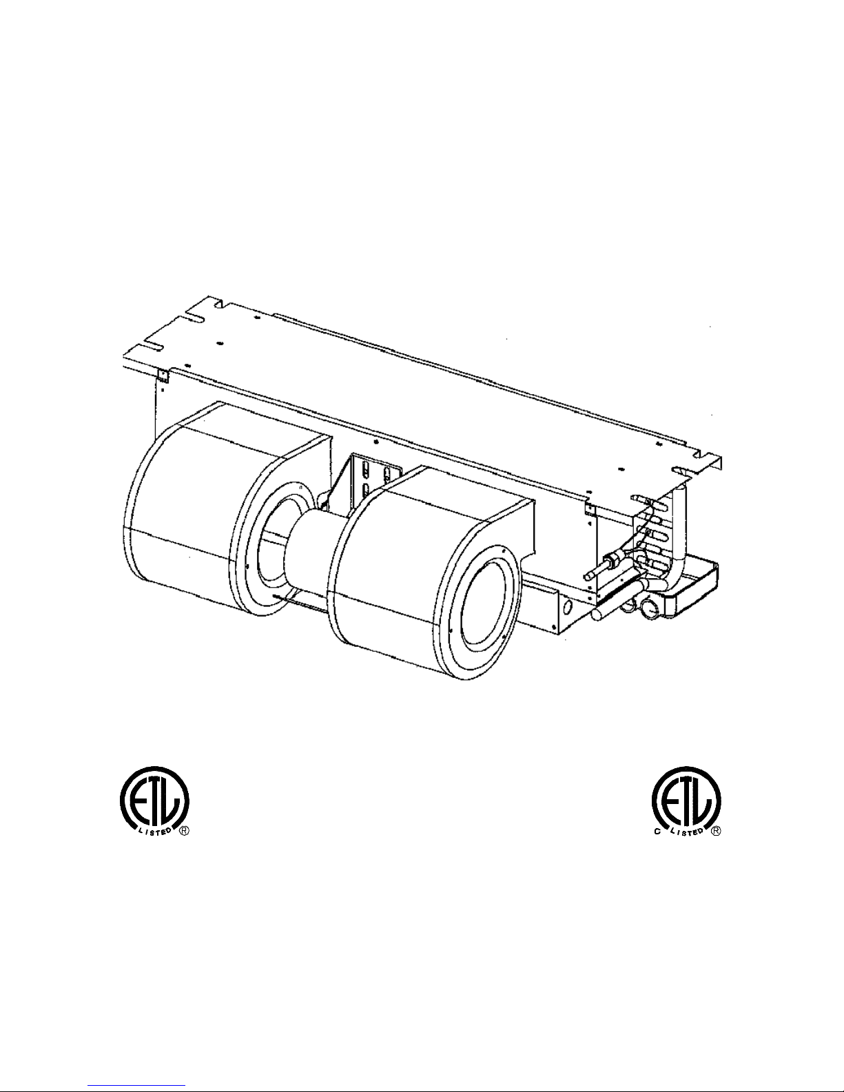
CEILING MOUNT AIR HANDLER
IO-162C 2550 North Loop West Suite 400 AC SERIES 4/02
AC SERIES
CERTIFIED
Made in the USA by:
Goodman Manufacturing Company, L.P.
Houston, Texas 77092
Page 2
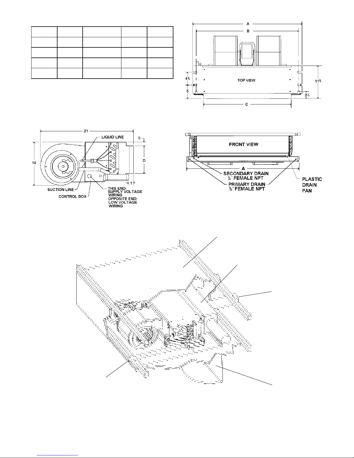
Dimensions
Model A B C D
AC 18 37 1/4 37 11/16 30 6 1/2
AC 24 37 1/4 37 11/16 30 6 1/2
AC 30 43 1/4 40 11/16 36 6 1/2
AC 36 49 1/4 46 11/16 42 6 1/2
ELECT. HEATER
LOCATION
AC 18, 24, 30, 36
FIGURE 1
LAYOUT FOR
To Drain
Drop Ceiling
Plenum
Outlet Duct
Grill For Return Air
And Service
FIGURE 2
DROP CEILING
INSTALLATION
2
Page 3
SPECIAL INSTRUCTIONS
This indoor coil contains the flowrator distributor assembly, which consist of a flare nut, distributor body, copper tubes
feeding the coil, and the internal flow check piston. Reference the enclosed “Piston Sizing Chart” for mix-matching of
outdoor / indoor units.
CHANGE THE PISTON
This coil is furnished with a flow control piston installed that matches the BTUH capacity of the coil. A piston size that is
too small will cause starving and one that is too large will cause flooding. The following chart indicates the condensing
unit capacity and the recommended piston size.
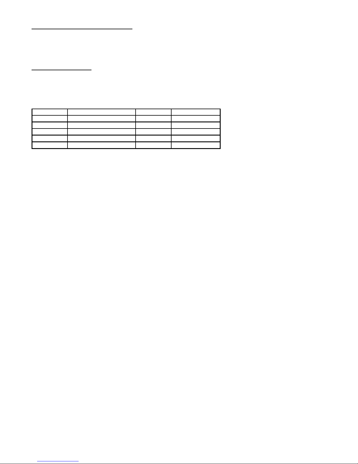
CONDENSING UNIT
MODEL NOM. COOLING (BTUH) PART NO. PISTON SIZE
AC18 18,000 BT 13690-04 52
AC24 24,000 BT 13690-01 59
AC30 30,000 BT 13690-05 65
AC36 36,000 BT 13690-06 71
1. Using a back-up wrench on the flare fitting, remove the
3/8" flare nut.
2. Using the back-up wrench on the distributor body,
6. Replace 3/8" flare fitting with Teflon seal using back-up
remove the 3/8" flare fitting and Teflon seal.
3. Using the wire provided with replacement pistons, run
wire (hooked end) through hole in piston.
7. Replace 3/8" flare nut using back-up wrench on flare
4. Hook nose end of piston and lift gently from distributor
body.
8. Remove old piston size label from outside of distributor
5. Replace piston with one of proper size listed above,
install piston with Teflon seal end of piston in distributor
first. Do not force piston into distributor.
9. Check fitting for leaks after installation, evacuation and
NOTE: With piston in distributor, seal end should be
shown and should not be seen looking in end of
distributor. Piston must be free to rotate and move up
If a combination is used that requires
a piston size change, change the
piston in the distributor on the indoor
coil before installing the coil and
follow the procedure shown below.
and down. Make sure piston is free to move in distributor
body.
wrench on distributor body. Torque fitting with 8 to 10 ft.
lb. Do not over tighten.
fitting. Torque 3/8" flare nut with 40 to 45 ft. lb.
body. Remove new piston size label from poly bag new
piston came in and install new size label on outside of
distributor.
charging of the low side is complete.
INTRODUCTION
WARNING: DO NOT CONNECT TO OR USE IN CONJUNCTION WITH THIS UNIT ANY DEVICES FOR THE PURPOSE OF SAVING
ENERGY OR INCREASING OPERATING EFFICIENCIES, WHICH HAVE NOT BEEN TESTED AND APPROVED BY GOODMAN
OR DESIGN CERTIFIED FOR USE WITH THIS UNIT. SERIOUS DAMAGE, REDUCED UNIT PERFORMANCE AND HAZARDOUS
CONDITIONS MAY RESULT FROM THE USE OF DEVICES WHICH HAVE NOT BEEN APPROVED OR CERTIFIED BY
GOODMAN.
This booklet contains the installation and operating instructions
for your ceiling mount air handler. There are a few precautions
that should be taken to derive maximum satisfaction from it.
Improper installation can result in unsatisfactory operation or
dangerous conditions and void the warranty. Read this booklet
and any instructions packaged with accessories prior to
installation. Give this booklet to the user and explain its
provisions. The user should retain this booklet for future
reference.
CHECKING PRODUCT RECEIVED
Upon receiving the unit, inspect it for any damage from shipment.
Claims for damage, either shipping or concealed, should be
filed immediately with the shipping company. Check the unit
model number, specifications, electrical characteristics,
and accessories to determine if they are correct.
ORDERING PARTS
When reporting shortages or damages, or ordering repair parts,
give the complete unit model and serial numbers as stamped
on the unit’s nameplate. Order parts through your local
contractor.
3
Page 4

I. SPECIFICATIONS
A. GENERAL
These Ceiling mount air handlers are available in
cooling capacities of 1.5, 2, 2.5 and 3 nominal tons of
cooling. Electric heat models are available in capacities of 5, 8 and 10 KW.
B. INSTALLATION
1. Before locating the unit on the dropped ceiling, make
sure that the strength of the ceiling and beams is
adequate at the point to support the weight involved.
This is very important and installers responsibility. The
following list shows approximate weight of unit.
The units are designed to be installed in a horizontal
position above a dropped ceiling. Units are not to be
installed outside the structure. These models are
designed for INDOOR USE ONLY.
The information on the rating plate is in compliance with
the FTC and DOE rating for single phase units in the
U.S.A..
IMPORTANT: The United States Environmental
Protection Agency (EPA) has issued various regulations regarding the introduction and disposal of
refrigerants in this unit. Failure to follow these
regulations may harm the environment and can
lead to the imposition of substantial fines. Because these regulations may vary due to the
passage of new laws we suggest that any work on
this unit be done by a certified technician. Should
you have any questions please contact the local
office of the EPA.
B. MAJOR COMPONENTS
The unit includes a evaporator coil with flowrator assembly, an indoor blower and all necessary internal
electrical wiring. The cooling system of these units is
factory-evacuated, charged and performance tested.
Refrigerant amount and type are indicated on rating
plate.
MODEL WEIGHT (lb.)
AC18 59
AC24 59
AC30 69
AC36 79
2. The unit should be mounded on a horizontal position
above a dropped ceiling of adequate strength (see
Figure 2)
3. The location of the unit should provide proper access for
inspection and servicing.
C. DUCTING
Duct work should be fabricated by the installing contractor in accordance with local codes. Industry manuals may be used as a guide when sizing and designing
the duct system - such as NESCA (National Environmental Systems Contractors Association, 1501 Wilson Blvd., Arlington, Virginia 22209).
DO NOT, UNDER ANY CIRCUMSTANCES, CONNECT DUCT WORK TO ANY OTHER HEAT PRODUCING DEVICE SUCH AS FIREPLACE INSERT, STOVE,
ETC. UNAUTHORIZED USE OF SUCH DEVICES MAY
RESULT IN FIRE, CARBON MONOXIDE POISONING,
EXPLOSION, PERSONAL INJURY OR PROPERTY
DAMAGE.
II. INSTALLATION
A. GENERAL
1a. INSTALLATION — This product is designed and
manufactured to permit installation in accordance
with National Codes. It is the installer’s responsibility to install the product in accordance with
National Codes and/or prevailing local codes and
regulations.
1b. PRE-INSTALLATION CHECK-POINTS — Before at-
tempting any installation, the following points
should be considered:
Structural strength of supporting members
Clearances and provision for servicing
Power supply and wiring
Air duct connections
Drain facilities and connections
2b. LOCATION - These units are designed to be in-
stalled in a horizontal position above a dropped
ceiling. The location of the unit should be based
on thorough consideration of the PRE-INSTALLATION CHECK POINTS.
This unit should be placed as close to the space to be
air conditioned as possible. Adequate clearance must
be maintained as indicated in Section F “Clearances”.
Ducts should be run as directly as possible to supply
and return outlets. Use of non-flammable weatherproof
flexible connectors on both supply and return connections at unit to reduce noise transmission is recommended.
D. FILTERS
Filters are not provided with unit, and must be supplied
and installed in the return air system by the installer. A
field installed filter grille is recommended for easy and
convenient access to the filters, for periodic inspection
and cleaning. Filters must have adequate face area for
the rated air quantity of the unit. The minimum filter size
is 20" x 20" x 1".
E. CLEARANCES
These units are U.L. listed for installations with zero
clearance to combustible materials, reference should
be made to the marking on the particular unit being
installed where specific information regarding clearances is provided. Access must be provided for servic-
4
Page 5

ing the unit. If these units are installed in a removable
200
SUPPLY WIRE
150
TW (60C)
100
50
BRANCH CIRCUIT AMPACITY
ceiling panel, ample space must be provided for servicing the unit.
III. PIPING
CONDENSATE DRAIN
FIGURE 3
The condensate drain connection of the evaporator is a half
coupling of 3/4" N.P.T. A trap must be provided to have
proper condensate drainage. See Figure 3.
IV.ELECTRICAL WIRING
GENERAL
All wiring should be made in accordance with the
National Electrical Code in the U.S.A. Determine the
availability of sufficient power to operate the unit. The
voltage at the power supply should be checked to make
sure it corresponds to the unit’s RATED VOLTAGE
REQUIREMENT. Wire sizes should be determined
from the unit nameplate ampacity and in accordance
with Table 1, the National Electrical Code. Under no
circumstances should wiring be sized smaller than is
recommended by either of these two sources.
The unit must be permanently grounded in accordance
with local codes, or in the absence of local codes, with
the N.E.C. ANSI/NFPA NO. 70-1987 or latest edition in
the U.S.A. To wire units, make the following high and
low voltage connections at either location.
1. High Voltage Wiring:
These units are designed for Single phase 208/230 Volt
only, two leads should be connected to terminals L1
and L2 on the breaker in the electrical control section,
using wire sizes specified in table 1.
Install condensate drain trap as shown. Use 3/4" drain
connection size or larger. Do not operate without trap.
Unit must be level or slightly inclined toward drain.
TABLE 1
BRANCH CIRCUIT COPPER WIRE SIZE
(Base on 1% Voltage Drop)
6 4 4 4 3 3 2 2
8 6 6 4 4 4 3 3
10 8 8 6 6 6 4 4
LENGTH - FEET 75
12 10 8 8 6 6 4 4
14 12 18 10 8 8 6 6
15 20 25 30 35 40 45 50
NOTE: (Wiring for unit only, no heat kit installed)
a. Wire size based on 60°C rated wire insulation and 30°C
Ambient Temp. (86°F).
b. For branch circuit wiring (main power supply to unit
disconnect), the minimum wire size for the length of run
can be determined from Table 2 using the circuit
ampacity found on the unit rating plate. From the unit
disconnect to unit, the smallest wire size allowable in
Table 2 may be used, as the disconnect must be in
sight of the unit.
c. For more than 3 conductors in a raceway or cable, see
the N.E.C. for derating the ampacity of each conductor.
2. Low Voltage Wiring: See Figure 4 for cooling unit
with electric heat, Figure 5 for heat pump with
electric heat.
Connect 24V. wires from the thermostat to the corresponding wires in control box using No. 18 AWG as
follows:
LEAD THERMOSTAT NOTES
PINK R (24V) -
GREEN G (FAN) -
- Y TO CONDENSING UNIT 24V
CONNECTIONS
WHITE W -
BLUE - TO CONDENSING UNIT 24V
CONNECTIONS
BROWN E TO BE USED FOR
EMERGENCY HEAT ONLY
5
Page 6

3. Internal Wiring
A diagram of the internal wiring of this unit is located
under the electrical box cover. If any of the original wire
as supplied with the appliance must be replaced, the
wire gauge and insulation must be same as original
wiring.
4. Transformer is factory wired for 230 volts on 208/ 230 volt
models. See wiring diagram for 208 volt wiring. For 208V
operation, move the white transformer lead from 240V to
208V tap.
BLUE
YELLOW
Figure 4
R Y G W
THERMOSTAT
24 V CONNECTIONS
TO CONDENSING UNIT
MODEL
AC18, 24, 30, 36 2
THERMOSTAT HEAT
ANTICIPATOR SETTING
MAINTENANCE
1) Room Thermostat - This is the device that controls the
operation of your heating and/or cooling unit. It senses
the indoor temperature and signals the equipment to
start or stop maintaining the temperature you have
selected for your comfort. The room thermostat should
be in a central, draft free inside wall location for best
operation. Do not place any heat producing apparatus
such as lights, radio, etc., near the thermostat as this
will cause erratic operation of the comfort system.
2) Air Filter(s) - All central air moving comfort systems
must include air filter(s). These filters will be located
either in the equipment or in the return air duct system
upstream of the equipment. The filter(s) removes dust
and debris from the air thus helping to keep your
conditioned space clean. More important, the filter
keeps dust and debris from collecting on heat transfer
surfaces thus maintaining optimum equipment efficiency and performance. Inspect and clean or replace
filters every month. This routine maintenance procedure
will pay big dividends in reduced operating cost and
reduced service expense. Never operate comfort equipment without filter(s).
Figure 5
Electrical Installation Diagram For Cooling
Electrical Installation Diagram For Heat pump
unit with Electric Heat.
With Electric Heat.
NOTE: In case of heat pump failure, switch to
“E” on T’stat for emergency heat.
3) Fuses and/or Circuit breakers - This comfort equipment should be connected to the building electric
service in accordance with local and National Electric
codes. This electrical connection will include over
current protection in the form of fuses or circuit breakers. Have your contractor identify the circuits and the
location of over current protection so that you may be in
a position to make inspections or replacements in the
event the equipment fails to operate. Keep replacement
fuses of the proper size on hand.
6
Page 7

WARNING
a. Dirty condenser coil
a. Clean coil
b. Correct system charge
a. Incorrect capillary tube
a. Replace evaporator assembly
a. Power off or loose electrical connection
b. Thermostat cut off calibration set too high
c. Defective contactor
d. Blown fuses or tripped breaker
e. Tansformer defective
f. High or low pressure control open (Optional)
a. Check for unit voltage at contactor in unit
b. Reset
contacts are open
d. Replace fuse or reset breaker
e. Check wiring-replace transformer
f. Reset high pressure control or check unit charge
High pressure control opens at 425psi
Low pressure control opens at 25psi
g. Replace compressor
a. Loose connection
winding/open internal overload
tighten all connections
open, replace the compressor
10% of nameplate voltage when unit is operating
a. Defective overload protector
a. Check for correct voltage/replace overload
replace air filters
a. Excessive load
a. Recheck load calculation
a. Improperly sized unit
b. Improper airflow
c. Incorrect refrigerant charge
a. Recalculate load
b. Check (should be approximately 400 cfm/ton)
c. Charge per unit service panel
a. Low airflow
b. Low refrigerant charge
dirty air filters, all duct outlets open
b. Properly charge unit
open below 65 degrees F outdoor temperature
a) Do not store combustible materials or use gasoline or other flammable liquids or vapors in the vicinity of
this appliance so as to prevent the risk of property damage or personal injury.
b) Have your contractor point out and identify the various cut-off devices, switches, etc., that serve your
comfort equipment. There is a switch that will cut off energy to your heating system. Know where they are
so that you may cut off the flow of energy in the event of overheating.
4) Periodic Checkup and Service - This product is designed to provide many years of dependable, trouble-free comfort
when properly maintained. Proper maintenance will consist of annual checkups and cleaning of the internal electrical
and heat transfer components by a qualified service technician. Failure to provide periodic checkup and cleaning can
result in excessive operating cost and/or equipment malfunction.
TROUBLESHOOTING CHART
WARNING: DISCONNECT ALL POWER TO UNIT BEFORE SERVICING
SYMPTOM POSSIBLE CAUSE REMEDY
High head-low suction a. Restriction in liquid line or capillary tube a. Remove or replace defective component
High head-high or normal
suction
Low head-high suction
Unit will not run
b. Overcharged
c.Condenser fan not running
b. Defective compressor valves
c. repair or replace
b. Replace compressor
c. Check for 24 volts at contactor coil replace if
g. Compressor overload contacts open
NOTE: Wait at least 2 hours for overload to reset
Condenser fan runs,
compressor does not
Low suction-cool
compressor
Compressor short cycles
Registers sweat a. Low airflow a. Increase speed of blower or reduce restriction-
High suction pressure
Insufficient cooling
Evaporator coil freezing or
frosting
b. Compressor stuck, grounded or open
c. Low voltage connection
a. Low indoor airflow a. Increase speed of blower or reduce restriction-
b. Unit cycling on low pressure control
b. Deffective compressor
d. Incorrect voltage
c. Operating unit in cooling mode below 65
degrees F outdoor temperature
a. Check for unit voltage at compressor check and
b. Wait at least 2 hours for overload to reset if still
c. At compressor terminals, voltage must be within
replace air filters
b. Check refrigerant charge and airflow
b. Replace
d. At compressor terminals, voltage must be within
10% of nameplate voltage when unit is operating
a. Check (should be approximately 400 cfm/ton),
c. Install or check low ambient control, should be
7
 Loading...