


INSTALLATION & OPERATING
INSTRUCTIONS for
GPG13
SINGLE PACKAGE GAS-ELECTRIC
HEATING& COOLINGUNIT
Affix this manual and Users Information Manual adjacent to the unit.
®
|
|
|
|
|
|
|
|
|
|
|
|
|
|
|
C |
US |
|
|
|
|
|
|
|
|
|
|
|
|
|
|
|
|
|||
|
|
|
|
|
|
|
|
|
|
|
|
|
|
|
|
|
|
|
|
|
|
|
|
|
|
|
|
|
|
|
|
|
|
|
|
|
|
|
|
|
|
|
|
|
|
|
|
|
|
|
|
|
|
|
|
|
|
|
|
|
|
|
|
|
|
|
|
|
|
|
|
|
|
|
|
|
|
|
|
|
|
|
|
|
|
|
|
|
|
This Forced Air Central Unit Design Complies With
Requirements Embodied in The American National
Standard / National Standard of Canada Shown Below.
ANSI Z21.47•CSA-2.3 Central Furnaces
 RECOGNIZE THIS SYMBOL AS A SAFETY PRECAUTION.
ATTENTION INSTALLING PERSONNEL
Prior to installation, thoroughly familiarize yourself with this Installation Manual. Observe all safety warnings. During installation or repair, caution is to be observed.
It is your responsibility to install the product safely and to educate the customer on its safe use.
These installation instructions cover the outdoor installation of single package gas electric heating and cooling units. See the Product Data Book applicable to your model* for information regarding accessories.
*NOTE: Please contact your distributor or our website for the applicable product data
book referred to in this manual.
|
Goodman Manufacturing Company, L.P. |
|
|
|
|
|
|
|
|
|
|
|
|
|
|
IO-288B |
5151 San Felipe, Suite 500, Houston, TX 77056 |
|
|
|
|
|
|
|
|
|
|
|
|
|
|
07/08 |
www.goodmanmfg.com |
|
|
|
|
|
|
|
|
|
|
|
|
|
|
© 2005 - 2008 Goodman Manufacturing Company, L.P.
|
INDEX |
Replacement Parts ............................................................................................................................................................. |
3 |
ORDERING PARTS .............................................................................................................................................. |
3 |
Safety Instructions ............................................................................................................................................................. |
3 |
Unit location ........................................................................................................................................................................ |
4 |
ALL INSTALLATIONS: ........................................................................................................................................... |
4 |
GROUND LEVEL INSTALLATIONS ONLY: .................................................................................................................. |
4 |
ROOFTOP INSTALLATIONS ONLY:........................................................................................................................... |
4 |
ROOF CURB INSTALLATIONS ONLY: ....................................................................................................................... |
5 |
General Information ........................................................................................................................................................... |
5 |
TRANSPORTATION DAMAGE ................................................................................................................................... |
6 |
Rigging Details ................................................................................................................................................................... |
6 |
Gas piping ........................................................................................................................................................................... |
6 |
HIGH ALTITUDE DERATE (U.S. INSTALLATIONS ONLY) ............................................................................................... |
6 |
PIPING ............................................................................................................................................................. |
6 |
GAS PIPING CHECKS .......................................................................................................................................... |
7 |
Propane Gas Installations .................................................................................................................................................. |
7 |
TANKS AND PIPING ............................................................................................................................................. |
8 |
Electrical Wiring ................................................................................................................................................................. |
8 |
THERMOSTAT LOCATION ....................................................................................................................................... |
8 |
UNIT VOLTAGE ................................................................................................................................................... |
9 |
HEAT ANTICIPATOR SETTING .................................................................................................................................. |
9 |
Circulating Air and Filters ................................................................................................................................................ |
10 |
AIRFLOW CONVERSION ...................................................................................................................................... |
10 |
DUCTWORK ...................................................................................................................................................... |
10 |
FILTERS .......................................................................................................................................................... |
10 |
Venting ............................................................................................................................................................................... |
11 |
FLUE HOOD INSTALLATION ................................................................................................................................... |
11 |
Condensate Drain .............................................................................................................................................................. |
11 |
CONDENSATE DRAIN CONNECTION ........................................................................................................................ |
11 |
Normal sequences of operation ....................................................................................................................................... |
11 |
HEATING .......................................................................................................................................................... |
11 |
COOLING ......................................................................................................................................................... |
11 |
FAN ONLY ...................................................................................................................................................... |
12 |
Startup, Adjustments, and Checks .................................................................................................................................. |
12 |
HEATING STARTUP ............................................................................................................................................ |
12 |
COOLING STARTUP ........................................................................................................................................... |
15 |
Troubleshooting ................................................................................................................................................................ |
15 |
IGNITION CONTROL ERROR CODES ...................................................................................................................... |
15 |
ABNORMAL OPERATION - HEATING .................................................................................................................... |
16 |
ABNORMAL OPERATION - COOLING ................................................................................................................... |
16 |
Maintenance ..................................................................................................................................................................... |
17 |
FILTER REPLACEMENT OR CLEANING .................................................................................................................... |
17 |
CABINET FINISH MAINTENANCE ........................................................................................................................... |
17 |
CLEAN OUTSIDE COIL (QUALIFIED SERVICER ONLY) ............................................................................................. |
17 |
CONDENSER, EVAPORATOR, AND INDUCED DRAFT MOTORS ..................................................................................... |
17 |
FLAME SENSOR (QUALIFIED SERVICER ONLY) ...................................................................................................... |
17 |
FLUE PASSAGES (QUALIFIED SERVICER ONLY) ..................................................................................................... |
17 |
CLEANING FLUE PASSAGES (QUALIFIED SERVICER ONLY) ...................................................................................... |
17 |
MAIN BURNER FLAME (QUALIFIED SERVICER ONLY) .............................................................................................. |
18 |
CLEANING BURNERS ......................................................................................................................................... |
18 |
Accessories and Functional Parts ................................................................................................................................... |
18 |
SHEET METAL ACCESSORIES .............................................................................................................................. |
18 |
FUNCTIONAL PARTS .......................................................................................................................................... |
18 |
GENERAL INFORMATION ..................................................................................................................................... |
18 |
Ignition Control Diagnostic Indicator Chart .................................................................................................................... |
19 |
Heating Timing Chart ....................................................................................................................................................... |
19 |
Cooling Timing Chart ....................................................................................................................................................... |
19 |
APPENDIX ......................................................................................................................................................................... |
20 |
Wiring Diagrams .......................................................................................................................................................... |
21-36 |
Minimum Clearances ....................................................................................................................................................... |
37 |
Recommended Filter Sizes ............................................................................................................................................. |
37 |
2

REPLACEMENT PARTS
ORDERING PARTS
When reporting shortages or damages, or ordering repair parts, give the complete unit model and serial numbers as stamped on the unit’s nameplate.
Replacement parts for this appliance are available through your contractor or local distributor. For the location of your nearest distributor, consult the white business pages, the yellow page section of the local telephone book or contact:
SERVICE PARTS DEPARTMENT
GOODMAN MANUFACTURING COMPANY, L.P.
5151 SAN FELIPE, SUITE 500
HOUSTON, TEXAS 77056 (713) 861 – 2500
SAFETY INSTRUCTIONS
TO THE INSTALLER
Before installing this unit, please read this manual to familiarize yourself on the specific items which must be adhered to, including maximum external static pressure to unit, air temperature rise, minimum or maximum CFM and motor speed connections.
TO THE OWNER
A warranty certificate is provided with the unit. Read the warranty carefully and note what is covered. Keep the warranty certificate in a safe place so you can find it when necessary.
Keep this literature in a safe place for future reference.
 WARNING
THIS PRODUCT CONTAINS OR PRODUCES A CHEMICAL OR CHEMICALS WHICH MAY CAUSE SERIOUS ILLNESS OR DEATH AND WHICH ARE KNOWN TO THE STATE OF CALIFORNIA TO CAUSE CANCER, BIRTH DEFECTS OR OTHER REPRODUCTIVE HARM.
 WARNING
HEATING UNIT SHOULD NOT BE UTILIZED WITHOUT REASONABLE, ROUTINE, INSPECTION, MAINTENANCE AND SUPERVISION. IF THE BUILIDNG IN WHICH ANY SUCH DEVICE IS LOCATED WILL BE VACANT, CARE SHOULD BE TAKEN THAT SUCH DEVICE IS ROUTINELY INSPECTED, MAINTAINED AND MONITORED. IN THE EVENT THAT THE BUILDING MAYBE EXPOSED TO FREEZING TEMPERATURES AND WILL BE VACANT, ALL WATER-BEARING PIPES SHOULD BE DRAINED, THE BUILDING SHOULD BE PROPERLY WINTERIZED, AND THE WATER SOURCE CLOSED. IN THE EVENT THAT THE BUILDING MAY BE EXPOSED TO FREEZING TEMPERATURES AND WILL BE VACANT, ANY HYDRONIC COIL UNITS SHOULD BE DRAINED AS WELL AND, IN SUCH CASE, ALTERNATIVE HEAT SOURCES SHOULD BE UTILIZED.
 WARNING
TO AVOID PROPERTY DAMAGE, PERSONAL INJURY OR DEATH, DO NOT USE THIS UNIT IF ANY PART HAS BEEN UNDER WATER. IMMEDIATELY CALL A QUALIFIED SERVICE TECHNICIAN TO INSPECT THE FURNACE AND TO REPLACE ANY PART OF THE CONTROL SYSTEM AND ANY GAS CONTROL HAVING BEEN UNDER WATER.
WARNING |
WARNING |
IF THE INFORMATION IN THESE INSTRUCTIONS IS NOT FOLLOWED EXACTLY, A FIRE OR EXPLOSION MAY RESULT CAUSING PROPERTY DAMAGE, PERSONAL INJURY OR LOSS OF LIFE.
– DO NOT STORE OR USE GASOLINE OR OTHER FLAMMABLE VAPORS AND
LIQUIDS IN THE VICINITY OF THIS OR ANY OTHER APPLIANCE.
–WHAT TO DO IF YOU SMELL GAS:
•DO NOT TRY TO LIGHT ANY APPLIANCE.
•DO NOT TOUCH ANY ELECTRICAL SWITCH; DO NOT USE ANY
PHONE IN YOUR BUILDING.
• IMMEDIATELY CALL YOUR GAS SUPPLIER FROM A NEIGHBOR’S PHONE. FOLLOW THE GAS SUPPLIER’S INSTRUCTIONS.
• IF YOU CANNOT REACH YOUR GAS SUPPLIER, CALL THE FIRE DEPARTMENT.
– INSTALLATION AND SERVICE MUST BE PERFORMED BY A QUALIFIED INSTALLER, SERVICE AGENCY OR THE GAS SUPPLIER.
 WARNING
SHOULD OVERHEATING OCCUR OR THE GAS SUPPLY FAIL TO SHUT OFF, TURN OFF THE MANUAL GAS SHUTOFF VALVE EXTERNAL TO THE FURNACE BEFORE TURNING OFF THE ELECTRICAL SUPPLY.
 WARNING
DO NOT CONNECT TO OR USE ANY DEVICE THAT IS NOT DESIGN CERTIFIED BY GOODMAN FOR USE WITH THIS UNIT. SERIOUS PROPERTY DAMAGE, PERSONAL INJURY, REDUCED UNIT PERFORMANCE AND/OR HAZARDOUS CONDITIONS MAY RESULT FROM THE USE OF SUCH NON-APPROVED DEVICES.
THIS UNIT MUST NOT BE USED AS A "CONSTRUCTION HEATER" DURING THE FINISHING PHASES OF CONSTRUCTION ON A NEW STRUCTURE. THIS TYPE OF USE MAY RESULT IN PREMATURE FAILURE OF THE UNIT DUE TO EXTREMELY LOW RETURN AIR TERMPERATURES AND EXPOSURE TO CORROSIVE OR VERY DIRTY ATMOSPHERES.
 WARNING
TO PREVENT THE RISK OF PROPERTY DAMAGE, PERSONAL INJURY, OR DEATH, DO NOT STORE COMBUSTIBLE MATERIALS OR USE GASOLINE OR OTHER FLAMMABLE LIQUIDS OR VAPORS IN THE VICINITY OF THIS APPLIANCE.
3
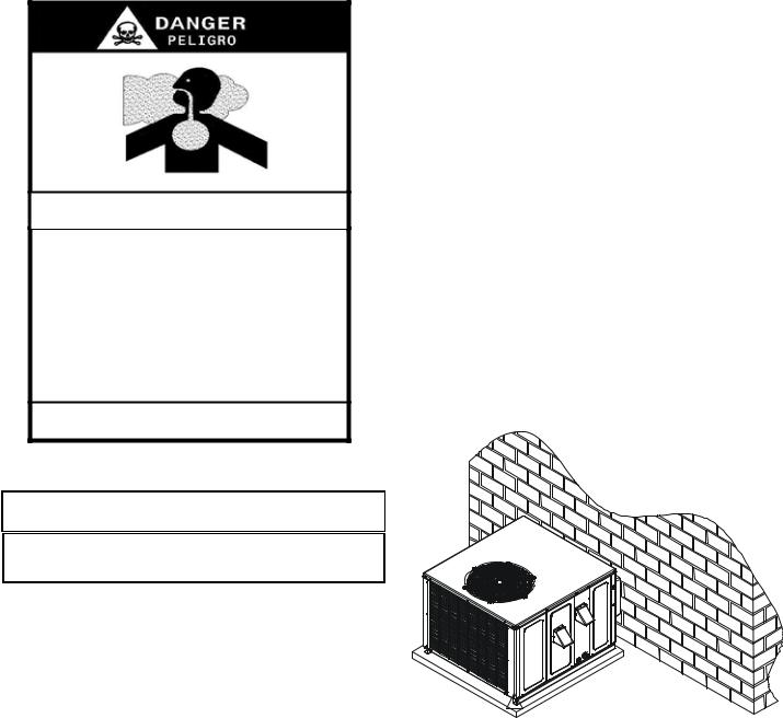
CARBON MONOXIDE POISONING HAZARD
Special Warning for Installation of Furnaces or Air Handling Units in
Enclosed Areas such as Garages, Utility Rooms or Parking Areas
Carbon monoxide producing devices (such as an automobile, space heater, gas water heater, etc.) should not be operated in enclosed areas such as unventilated garages, utility rooms or parking areas because of the danger of carbon monoxide (CO) poisoning resulting from the exhaust
emissions. If a furnace or air handler is installed in an enclosed area such as a garage, utility room or parking area and a carbon monoxide producing device is operated therein, there must be adequate, direct outside ventilation.
This ventilation is necessary to avoid the danger of CO poisoning which can occur if a carbon monoxide producing device continues to operate in the enclosed area. Carbon monoxide emissions can be (re)circulated throughout the structure if the furnace or air handler is operating in any mode.
CO can cause serious illness including permanent brain damage or death.
B10259-216
UNIT LOCATION
 WARNING
TO PREVENT POSSIBLE EQUIPMENT DAMAGE, PROPERTY DAMAGE, PERSONAL INJURY OR DEATH, THE FOLLOWING BULLET POINTS MUST BE OBSERVED WHEN INSTALLING THE UNIT.
IMPORTANT NOTE: Remove wood shipping rails prior to installation of the unit.
ALL INSTALLATIONS:
•For proper flame pattern within the heat exchanger and proper condensate drainage, the unit must be mounted level.
•The flue outlet hood must be at least 12 inches from any opening through which flue gases could enter a building, and at least three feet above any forced air inlet located within ten feet. The economizer/manual fresh air intake/ motorized fresh air intake and combustion air inlet mounted on the unit are not affected by this restriction.
•To avoid possible corrosion of the heat exchanger, do not locate the unit in an area where the outdoor air (i.e. combustion air for the unit) will be frequently contaminated by compounds containing chlorine or fluorine. Common sources of such compounds include swimming pool chemicals and chlorine bleaches, paint stripper, adhesives, paints, varnishes, sealers, waxes (which are not yet dried) and solvents used during construction and remodeling. Various commercial and industrial processes may also be sources of chlorine/fluorine compounds.
•To avoid possible illness or death of the building occupants, do NOT locate outside air intake device (economizer, manual fresh air intake, motorized fresh air intake) too close to an exhaust outlet, gas vent termination, or plumbing vent outlet. For specific distances required, consult local codes.
•Allow minimum clearances from the enclosure for fire protection, proper operation, and service access (see appendix). These clearances must be permanently maintained.
•The combustion air inlet and flue outlet hoods on the unit must never be obstructed. If used, do not allow the economizer/manual fresh air damper/ motorized fresh air damper to become blocked by snow or debris. In some climates or locations, it may be necessary to elevate the unit to avoid these problems.
•When the unit is heating, the temperature of the return air entering the unit must be between 50° F and 100° F.
GROUND LEVEL INSTALLATIONS ONLY:
•When the unit is installed on the ground adjacent to the building, a level concrete (or equal) base is recommended. Prepare a base that is 3” larger than the package unit footprint and a minimum of 3” thick.
•The base should also be located where no runoff of water from higher ground can collect in the unit.
Outside Slab Installation
ROOFTOP INSTALLATIONS ONLY:
NOTE: To ensure proper condensate drainage, unit must be installed in a level position.
•To avoid possible property damage or personal injury, the roof must have sufficient structural strength to carry the weight of the unit(s) and snow or water loads as required by local codes. Consult a structural engineer to determine the weight capabilities of the roof.
4
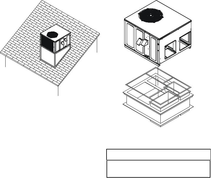
RooftopInstallation
•The unit may be installed directly on wood floors or on Class A, Class B, or Class C roof covering material.
•To avoid possible personal injury, a safe, flat surface for service personnel should be provided.
ROOF CURB INSTALLATIONS ONLY:
•Sufficient structural support must be determined prior to locating and mounting the curb and package unit.
•Ductwork must be constructed using industry guidelines. The duct work must be placed into the roof curb before mounting the package unit.
•Curb insulation, cant strips, flashing and general roofing material are furnished by the contractor.
Roof Curb Installation
GENERAL INFORMATION
 WARNING
TO PREVENT PROPERTY DAMAGE, PERSONAL INJURY OR DEATH, DUE TO FIRE, EXPLOSIONS, SMOKE, SOOT, CONDENSATION, ELECTRIC SHOCK OR CARBON MONOXIDE, THIS UNIT MUST BE PROPERLY INSTALLED, REPAIRED, OPERATED, AND MAINTAINED.
This unit is approved for outdoor installation ONLY. To assure that your unit operates safely and efficiently, it must be installed, operated, and maintained in accordance with these installation and operating instructions, all local building codes and ordinances, or in their absence, with the latest edition of the National Fuel Gas Code NFPA54/ANSI Z223.1 and National Standard of Canada CAN/CSA B149 Installation Codes.
The heating and cooling capacities of the unit should be greater than or equal to the design heating and cooling loads of the area to be conditioned. The loads should be calculated by an approved method or in accordance with A.S.H.R.A.E. Guide or Manual J - Load Calculations published by the Air Conditioning Contractors of America.
Obtain from:
American National Standards Institute
1430 Broadway
New York, NY 10018
5
TRANSPORTATION DAMAGE
Check the carton upon arrival for external damage. If damage is found, a request for inspection by carrier agent should be made in writing immediately.
Carefully inspect the unit for damage including damage to the cabinetry. Any bolts or screws which may have loosened in transit must be re-tightened. In the event of damage, the receiver should:
1.Make notation on delivery receipt of any visible damage to shipment or container.
2.Notify carrier promptly and request an inspection.
3.In case of concealed damage, carrier should be notified as soon as possible-preferably within 5 days.
4.File the claim with the following supporting documents:
a.Original Bill of Lading, certified copy, or indemnity bond.
b.Original paid freight bill or indemnity in lieu thereof.
c.Original invoice or certified copy thereof, showing trade and other discounts or reductions.
d.Copy of the inspection report issued by carrier representative at the time damage is reported to the carrier. The carrier is responsible for making prompt inspection of damage and for a thorough investigation of each claim. The distributor or manufacturer will not accept claims from dealers for transportation damage.
NOTE: When inspecting the unit for transportation damage, remove all packaging materials. Recycle or dispose of the packaging material according to local codes.
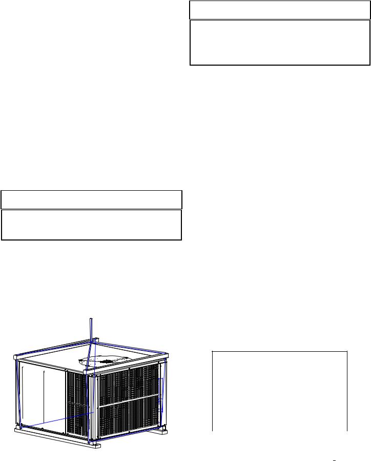
RIGGING DETAILS
 WARNING
TO PREVENT PROPERTY DAMAGE, THE UNIT SHOULD REMAIN IN AN UPRIGHT POSITION DURING ALL RIGGING AND MOVING OPERATIONS. TO FACILITATE LIFTING AND MOVING WHEN A CRANE IS USED, PLACE THE UNIT IN AN ADEQUATE CABLE SLING.
Important: If using bottom discharge with roof curb, ductwork should be attached to the curb prior to installing the unit. Ductwork dimensions are shown in roof curb installation instructions.
Refer to the Roof Curb Installation Instructions for proper curb installation. Curbing must be installed in compliance with the National Roofing Contractors Association Manual.
Lower unit carefully onto roof mounting curb. While rigging unit, center of gravity will cause condenser end to be lower than supply air end.
Rigging
GAS PIPING
IMPORTANT NOTE: This unit is factory set to operate on natural gas at the altitudes shown on the rating plate.
 WARNING
TO AVOID PROPERTY DAMAGE, PERSONAL INJURY OR DEATH WHEN EITHER USING PROPANE GAS ALONE OR AT HIGHER ALTITUDES, OBTAIN AND INSTALL THE PROPER CONVERSION KIT(S). FAILURE TO DO SO CAN RESULT IN UNSATISFACTORY OPERATION AND/OR EQUIPMENT DAMAGE. HIGH ALTITUDE KITS ARE FOR U.S. INSTALLATIONS ONLY AND ARE NOT APPROVED FOR USE IN CANADA.
The rating plate is stamped with the model number, type of gas and gas input rating. Make sure the unit is equipped to operate on the type of gas available. Conversion to LP gas is permitted with the use of the factory authorized conversion kit LPT-00A.
|
Inlet Gas Pressure |
Natural |
Min. 5.0" W.C., Max. 10.0" W.C. |
Propane |
Min. 11.0" W.C., Max. 13.0" W.C. |
Inlet Gas Pressure Must Not Exceed the Maximum Value Shown in Table
Above.
The minimum supply pressure should not vary from that shown in the table above because this could prevent the unit from having dependable ignition. In addition, gas input to the burners must not exceed the rated input shown on the rating plate. Overfiring of the unit could result in premature heat exchanger failure.
HIGH ALTITUDE DERATE (U.S. INSTALLATIONS ONLY)
IMPORTANT NOTE: The gas/electric units naturally derate with altitude. Do not attempt to increase the firing rate by changing orifices or increasing the manifold pressure. This can cause poor combustion and equipment failure. At all altitudes, the manifold pressure must be within 0.3 inches W.C. of that listed on the nameplate for the fuel used. At all altitudes and with either fuel, the air temperature rise must be within the range listed on the unit nameplate.
Refer to the Installation Manual provided with the LP kit for conversion from natural gas to propane gas and for altitude adjustments.
PIPING
IMPORTANT NOTE: To avoid possible unsatisfactory operation or equipment damage due to under firing of equipment, do not undersize the natural/propane gas piping from the meter/tank to the unit. When sizing a trunk line, include all appliances on that line that could be operated simultaneously.
The rating plate is stamped with the model number, type of gas and gas input rating. Make sure the unit is equipped to operate on the type of gas available. The gas line installation must comply with local codes, or in the absence of local codes, with the latest edition of the National Fuel Gas Code NFPA 54/ANSI Z223.1.
Natural Gas Connection
Natural Gas Capacity of Pipe
in Cubic Feet of Gas Per Hour (CFH)
Length of |
|
Nominal Black Pipe Size (inches) |
|
||||
|
|
|
|
|
|
|
|
Pipe in Feet |
1/2 |
|
3/4 |
1 |
1 1/4 |
|
1 1/2 |
10 |
132 |
|
278 |
520 |
1050 |
|
1600 |
20 |
92 |
|
190 |
350 |
730 |
|
1100 |
30 |
73 |
|
152 |
285 |
590 |
|
980 |
40 |
63 |
|
130 |
245 |
500 |
|
760 |
50 |
56 |
|
115 |
215 |
440 |
|
670 |
60 |
50 |
|
105 |
195 |
400 |
|
610 |
70 |
46 |
|
96 |
180 |
370 |
|
560 |
80 |
43 |
|
90 |
170 |
350 |
|
530 |
90 |
40 |
|
84 |
160 |
320 |
|
490 |
100 |
38 |
|
79 |
150 |
305 |
|
460 |
Pressure = .50 PSIG or less and Pressure Drop of 0.3" W.C. (Based on 0.60 Specific Gravity Gas)
CFH = |
BTUH Furnace Input |
|
Heating Value of Gas (BTU/Cubic Foot) |
||
|
6
Refer to the Proper Piping Practice drawing for the general layout at the unit. The following rules apply:
1.Use black iron pipe and fittings for the supply piping. The use of a flex connector and/or copper piping is permitted as long as it is in agreement with local codes.
2.Use pipe joint compound on male threads only. Pipe joint compound must be resistant to the action of the fuel used.
3.Use ground joint unions.
4.Install a drip leg to trap dirt and moisture before it can enter the gas valve. The drip leg must be a minimum of three inches long.
5.Use two pipe wrenches when making connection to the gas valve to keep it from turning.
6.Install a manual shut-off valve in a convenient location (within six feet of unit) between the meter and the unit.
7.Tighten all joints securely.
8.The unit must be connected to the building piping by one of the following methods:
•Rigid metallic pipe and fittings
•Semirigid metallic tubing and metallic fittings (Aluminum alloy tubing must not be used in exterior locations)
•Listed gas appliance connectors used in accordance with the terms of their listing that are completely in the same room as the equipment
•In the prior two methods above the connector or tubing must be protected from physical and thermal damage. Aluminum alloy tubing and connectors must be coated to protect against external corrosion when in contact with masonry, plaster or insulation or are subject to repeated wettings by liquids (water - not rain water, detergents or sewage)
MANUAL
SHUT-OFF
VALVE
DRIP LEG
GROUND JOINT UNION
(INSTALLED AHEAD OF GAS VALVE)
GROMMET
Proper Piping Practice
NOTE: The unit gas supply entrance is factory sealed with plugs. Keep plugs in place until gas supply is ready to be installed. Once ready, replace the plugs with the supplied grommets and install gas supply line.
GAS PIPING CHECKS
 CAUTION
TO PREVENT PROPERTY DAMAGE OR PERSONAL INJURY DUE TO FIRE, THE FOLLOWING INSTRUCTIONS MUST BE PERFORMED REGARDING GAS CONNECTIONS AND PRESSURE TESTING:
• THE UNIT AND ITS GAS CONNECTIONS MUST BE LEAK TESTED BEFORE PLACING IN OPERATION. BECAUSE OF THE DANGER OF EXPLOSION OR FIRE, NEVER USE A MATCH OR OPEN FLAME TO TEST FOR LEAKS. NEVER EXCEED SPECIFIED PRESSURES FOR TESTING. HIGHER PRESSURE MAY DAMAGE GAS VALVE AND CAUSE OVERFIRING WHICH MAY RESULT IN PREMATURE HEAT EXCHANGE FAILURE.
• THIS UNIT AND ITS SHUT-OFF VALVE MUST BE DISCONNECTED FROM THE GAS SUPPLY DURING ANY PRESSURE TESTING OF THAT SYSTEM AT TEST PRESSURES IN EXCESS OF 1/2 PSIG (3.48 KPA).
• THIS UNIT MUST BE ISOLATED FROM THE GAS SUPPLY SYSTEM BY CLOSING ITS MANUAL SHUT-OFF VALVE DURING ANY PRESSURE
TESTING OF THE GAS SUPPLY PIPING SYSTEM AT TEST PRESSURES EQUAL TO OR LESS THAN 1/2 PSIG (3.48 KPA).
 WARNING
TO AVOID PROPERTY DAMAGE OR PERSONAL INJURY, BE SURE THERE IS NO OPEN FLAME IN THE VICINITY DURING AIR BLEEDING.
There will be air in the gas supply line after testing for leaks on a new installation. Therefore, the air must be bled from the line by loosening the ground joint union until pure gas is expelled. Tighten union and wait for five minutes until all gas has been dissipated in the air. Be certain there is no open flame in the vicinity during air bleeding procedure. The unit is placed in operation by closing the main electrical disconnect switch for the unit.
PROPANE GAS INSTALLATIONS
 WARNING
TO AVOID PROPERTY DAMAGE, PERSONAL INJURY OR DEATH DUE TO FIRE OR EXPLOSION CAUSED BY A PROPANE GAS LEAK, INSTALL A GAS DETECTING WARNING DEVICE. SINCE RUST CAN REDUCE THE LEVEL OF ODORANT IN PROPANE GAS, A GAS DETECTING WARNING DEVICE IS THE ONLY RELIABLE WAY TO DETECT A PROPANE GAS LEAK. CONTACT A LOCAL PROPANE GAS SUPPLIER ABOUT INSTALLING A GAS DETECTING WARNING DEVICE.
IMPORTANT NOTE: Propane gas conversion kits must be installed to convert units to propane gas.
All propane gas equipment must conform to the safety standards of the National Board of Fire Underwriters (See NBFU Manual 58).
For satisfactory operation, propane gas supply pressure must be within 9.7 - 10.3 inches W.C. at the manifold with all gas appliances in operation. Maintaining proper gas pressure depends on three main factors:
1.Vaporization rate, which depends on (a) temperature of the liquid, and (b) wetted surface area of the container or containers.
2.Proper pressure regulation.
3.Pressure drop in lines between regulators, and between second stage regulator and the appliance. Pipe size required will depend on length of pipe run and total load of all appliances.
7
TANKS AND PIPING
Complete information regarding tank sizing for vaporization, recommended regulator settings and pipe sizing is available from most regulator manufacturers and propane gas suppliers.
Since propane gas will quickly dissolve white lead or most standard commercial compounds, special pipe dope must be used. Shellac base compounds resistant to the actions of liquefied petroleum gases such as Gasolac®, Stalactic®, Clyde’s® or John Crane® are satisfactory.
See below for typical propane gas piping.
First Stage |
5 to 15 PSIG |
|
|
|
||
(20 PSIG Max.) |
|
|
|
|||
Regulator |
Continuous |
|||||
|
|
|||||
|
|
|
11" W.C. |
|||
200 PSIG |
|
|
Second Stage |
|
||
Maximum |
|
|
Regulator |
|
||
|
|
|
|
|
|
|
|
|
|
|
|
|
|
Typical Propane Gas Piping
Sizing Between First and Second Stage Regulator
Maximum Propane Capacities listed are based on 1 PSIG Pressure Drop at 10 PSIG Setting. Capacities in 1,000 BTU/HR
PIPE OR |
|
|
|
|
TUBING SIZE, O.D., TYPE L |
|
|
|
|
NOMINAL PIPE SIZE, |
||||||||||||
TUBING |
|
|
|
|
|
|
|
|
||||||||||||||
|
|
|
|
|
|
|
|
|
|
SCHEDULE 40 |
||||||||||||
LENGTH, |
|
|
|
|
|
|
|
|
|
|
|
|
|
|
|
|
|
|
||||
|
|
|
|
|
|
|
|
|
|
|
|
|
|
|
|
|
|
|
|
|
||
FEET |
|
|
|
|
|
|
|
|
|
|
|
|
|
|
|
|
|
|
|
|
|
|
|
|
|
|
3/8" |
|
1/2" |
|
|
5/8" |
|
3/4" |
|
|
7/8" |
|
|
1/2" |
|
3/4" |
|||
30 |
|
|
|
309 |
|
700 |
|
|
1,303 |
|
2,205 |
|
3,394 |
|
|
1,843 |
|
3,854 |
||||
40 |
|
|
|
265 |
|
599 |
|
|
1,115 |
|
1,887 |
|
2,904 |
|
|
1,577 |
|
3,298 |
||||
50 |
|
|
|
235 |
|
531 |
|
|
988 |
|
1,672 |
|
2,574 |
|
|
1,398 |
|
2,923 |
||||
60 |
|
|
|
213 |
|
481 |
|
|
896 |
|
1,515 |
|
2,332 |
|
|
1,267 |
|
2,649 |
||||
70 |
|
|
|
196 |
|
446 |
|
|
824 |
|
1,394 |
|
2,146 |
|
|
1,165 |
|
2,437 |
||||
80 |
|
|
|
182 |
|
412 |
|
|
767 |
|
1,297 |
|
1,996 |
|
|
1,084 |
|
2,267 |
||||
90 |
|
|
|
171 |
|
386 |
|
|
719 |
|
1,217 |
|
1,873 |
|
|
1,017 |
|
2,127 |
||||
100 |
|
|
|
161 |
|
365 |
|
|
679 |
|
1,149 |
|
1,769 |
|
|
961 |
|
2,009 |
||||
150 |
|
|
|
130 |
|
293 |
|
|
546 |
|
923 |
|
|
1,421 |
|
|
772 |
|
1,613 |
|||
200 |
|
|
|
111 |
|
251 |
|
|
467 |
|
790 |
|
|
1,216 |
|
|
660 |
|
1,381 |
|||
250 |
|
|
|
90 |
|
222 |
|
|
414 |
|
700 |
|
|
1,078 |
|
|
585 |
|
1,224 |
|||
300 |
|
|
|
89 |
|
201 |
|
|
378 |
|
634 |
|
|
976 |
|
|
530 |
|
1,109 |
|||
350 |
|
|
|
82 |
|
185 |
|
|
345 |
|
584 |
|
|
898 |
|
|
488 |
|
1,020 |
|||
400 |
|
|
|
76 |
|
172 |
|
|
321 |
|
543 |
|
|
836 |
|
|
454 |
|
949 |
|||
To convert to Capacities at 15 PSIG Settings -- Multiply by 1.130 |
|
|
|
|
|
|
||||||||||||||||
To convert to Capacities at 5 PSIG Settings -- Multiply by 0.879 |
|
|
|
|
|
|
|
|
|
|||||||||||||
Sizing Between Single or Second Stage Regulator and Appliance* |
|
|
|
|
|
|
|
|
|
|||||||||||||
Maximum Propane Capacities Listed are Based on 1/2" W.C. Pressure Drop at |
|
|
|
|
|
|
||||||||||||||||
11" W.C. Setting. Capacities in 1,000 BTU/HR |
|
|
|
|
|
|
|
|
|
|
|
|
|
|||||||||
|
|
|
|
|
|
|
|
|
|
|
|
|
|
|
|
|
|
|
|
|
|
|
PIPE OR |
|
|
TUBING SIZE, O.D., TYPE L |
|
|
|
|
NOMINAL PIPE SIZE, |
|
|||||||||||||
TUBING |
|
|
|
|
|
|
|
|||||||||||||||
|
|
|
|
|
|
SCHEDULE 40 |
|
|||||||||||||||
LENGTH, |
|
|
|
|
|
|
|
|
|
|
|
|
|
|
|
|||||||
|
|
|
|
|
|
|
|
|
|
|
|
|
|
|
|
|
|
|
|
|
|
|
FEET |
|
|
|
|
|
|
|
|
|
|
|
|
|
|
|
|
|
|
|
|
|
|
|
|
3/8" |
1/2" |
|
5/8" |
|
3/4" |
7/8" |
|
1/2" |
|
3/4" |
|
1" |
|
1-1/4" |
1-1/2" |
|||||
10 |
|
49 |
110 |
|
206 |
|
348 |
539 |
|
291 |
|
608 |
|
1,146 |
|
2,353 |
|
3,525 |
||||
20 |
|
34 |
76 |
|
141 |
|
239 |
368 |
|
200 |
|
418 |
|
788 |
|
1,617 |
|
2,423 |
||||
|
|
|
|
|
|
|
|
|
|
|
|
|
|
|
|
|
|
|
||||
30 |
|
27 |
61 |
|
114 |
|
192 |
296 |
|
161 |
|
336 |
|
632 |
|
1,299 |
|
1,946 |
||||
|
|
|
|
|
|
|
|
|
|
|
|
|
|
|
|
|
|
|
||||
40 |
|
23 |
52 |
|
97 |
|
164 |
253 |
|
137 |
|
284 |
|
541 |
|
1,111 |
|
1,665 |
||||
|
|
|
|
|
|
|
|
|
|
|
|
|
|
|
|
|
|
|
||||
50 |
|
20 |
46 |
|
86 |
|
146 |
224 |
|
122 |
|
255 |
|
480 |
|
985 |
|
1,476 |
||||
|
|
|
|
|
|
|
|
|
|
|
|
|
|
|
|
|
|
|
||||
60 |
|
19 |
42 |
|
78 |
|
132 |
203 |
|
110 |
|
231 |
|
436 |
|
892 |
|
1,337 |
||||
80 |
|
16 |
36 |
|
67 |
|
113 |
174 |
|
94 |
|
198 |
|
372 |
|
764 |
|
1,144 |
||||
100 |
|
14 |
32 |
|
59 |
|
100 |
154 |
|
84 |
|
175 |
|
330 |
|
677 |
|
1,014 |
||||
125 |
|
12 |
28 |
|
52 |
|
89 |
|
137 |
|
74 |
|
155 |
|
292 |
|
600 |
|
899 |
|||
|
|
|
|
|
|
|
|
|
|
|
|
|
|
|
|
|
|
|
|
|||
150 |
|
11 |
26 |
|
48 |
|
80 |
|
124 |
|
67 |
|
141 |
|
265 |
|
544 |
|
815 |
|||
|
|
|
|
|
|
|
|
|
|
|
|
|
|
|
|
|
|
|
|
|||
200 |
|
10 |
22 |
|
41 |
|
69 |
|
106 |
|
58 |
|
120 |
|
227 |
|
465 |
|
697 |
|||
|
|
|
|
|
|
|
|
|
|
|
|
|
|
|
|
|
|
|
|
|
||
250 |
|
9 |
|
19 |
|
36 |
|
61 |
|
94 |
|
51 |
|
107 |
|
201 |
|
412 |
|
618 |
||
|
|
|
|
|
|
|
|
|
|
|
|
|
|
|
|
|
|
|
|
|
||
300 |
|
8 |
|
18 |
|
33 |
|
55 |
|
85 |
|
46 |
|
97 |
|
182 |
|
374 |
|
560 |
||
350 |
|
7 |
|
16 |
|
30 |
|
51 |
|
78 |
|
43 |
|
89 |
|
167 |
|
344 |
|
515 |
||
400 |
|
7 |
|
15 |
|
28 |
|
47 |
|
73 |
|
40 |
|
83 |
|
156 |
|
320 |
|
479 |
||
|
|
|
|
|
|
|
|
|
|
|
|
|
|
|
|
|
|
|
|
|
|
|
*DATA IN ACCORDANCE WITH NFPA PAMPHLET NO. 54
Table 3 - Propane Gas Pipe Sizing
 WARNING
TO PREVENT PROPERTY DAMAGE OR SERIOUS PERSONAL INJURY DUE TO FIRE OR EXPLOSION CAUSED BY A PROPANE GAS LEAK, INSTALL A GAS DETECTING WARNING DEVICE.
IF THE PROPANE GAS UNIT IS INSTALLED IN AN EXCAVATED AREA OR A CONFINED SPACE, A WARNING DEVICE IS REQUIRED DUE TO:
• PROPANE GAS IS HEAVIER THAN AIR AND ANY LEAKING GAS CAN SETTLE IN ANY LOW AREAS OR CONFINED SPACES.
• PROPANE GAS ODORANT MAY FADE, MAKING THE GAS UNDETECTABLE EXCEPT WITH A WARNING DEVICE.
ELECTRICAL WIRING
THERMOSTAT LOCATION
Mount the thermostat approximately five feet above the floor, in an area that has an inside, vibration-free wall and has good air circulation.
Movement of air must not be obstructed by furniture, door, draperies, etc. The thermostat must not be mounted where it will be affected by drafts, hot or cold water pipes or air ducts in walls, radiant heat from fireplace, lamps, the sun, television, etc. Consult the Instruction Sheet packaged with thermostat for mounting instructions.
All units have one stage of heating and one stage of mechanical cooling. Units which will have economizers may use thermostats with one or two stages of cooling.
*PG1360***1A ONLY: These models have two stages of mechanical cooling. A 1-stage heat, 2-stage cooling thermostat is recommended for these models.
The units are designed for operation on 60 hertz current and at voltages as shown on the rating plate. All internal wiring in the unit is complete. It is necessary to bring in the power supply to the contactor as shown on the unit wiring diagram which is supplied with each unit. 24 volt wiring must be connected between the unit control panel and the room thermostat.
C R Y W G
LOW VOLTAGE CONNECTOR
|
B18099-18 |
1068-83-400A |
|
|
|
|
|
|
|
|
|
|
|
|
|
|
|
|
COOL |
|
|
|
|
|
|
|
|
|
|
|
HEAT |
|
|
|
L2 |
|
|
K4 |
|
|
|
|
|
|
|
|
L2 |
|
|
K3 |
|
|
|
|
|
|
|
|
|
|
|
|
|
|
|
|
UNUSED |
|
|
|
L2 |
|
|
|
|
|
|
|
|
|
|
|
L2 |
|
|
|
|
|
|
|
L1 |
|
|
|
|
|
|
|
|
|
|
|
L1 |
|
|
|
|
MODEL |
1068-400 |
|
|
K2 |
|
|
DI |
|
|
|
|
SYSTEM |
|
R |
K1 |
|
|
FS |
|
|
|
|
|
ANSI Z21.20 AUTOMATICIGNITION |
|
|
|
|
9 |
|
6 |
|
|
|
|
24VAC 50/60Hz 400mA MAX. |
|
10 12 |
12 12 |
9 |
6 |
3 |
|
|
|||
|
|
|
1 3 2 |
||||||||
Y |
|
9 |
6 |
|
1 2 3 |
||||||
11 |
11 |
8 |
5 |
2 |
|||||||
11 |
8 |
5 |
|
||||||||
W |
10 |
7 4 |
P1 1 |
||||||||
G |
10 |
7 7 |
4 |
4 |
|||||||
|
|
|
|
F1 |
|
|
|
|
|
ECON |
|
|
|
|
|
|
|
|
|
|
|
||
|
|
|
|
|
|
|
|
|
|
|
|
|
|
|
|
FUSE 3 AMP MAX |
|
|
|
|
120 |
||
|
STAGE |
|
|
|
|
|
P3 |
|
|
|
135 |
|
|
|
|
|
|
|
|
|
|
150 |
|
|
TWOFOR |
|
|
|
|
|
|
|
|
|
|
|
COMPRESSOR |
|
|
|
|
|
|
|
|
|
SPEED-UP |
|
BREAK |
|
|
|
|
|
|
|
P2 |
||
|
T2 |
|
|
|
|
|
|
|
|
|
|
|
|
|
C22 |
|
|
T1 |
|
|
|
|
|
Low Voltage Wiring
8
Y/Y2 C R Y1 W G
LOW VOLTAGE CONNECTOR
|
B18099-18 |
1068-83-400A |
|
|
|
|
|
|
|
|
|
|
|
|
|
|
COOL |
|
|
|
|
|
|
|
|
|
|
HEAT |
|
|
|
L2 |
|
|
K4 |
|
|
|
|
|
|
|
L2 |
|
|
K3 |
|
|
|
|
|
|
|
|
|
|
|
|
|
|
UNUSED |
|
|
|
L2 |
|
|
|
|
|
|
|
|
|
|
L2 |
|
|
|
|
|
|
L1 |
|
|
|
|
|
|
|
|
|
|
L1 |
|
|
|
|
MODEL |
1068-400 |
|
K2 |
|
|
DI |
|
|
|
|
SYSTEM |
|
R |
K1 |
|
FS |
|
|
|
|
|
AUTOMATICIGNITION |
|
|
|
9 |
|
6 |
|
|
|
|
MAX. |
12 |
12 12 |
9 6 |
3 |
|
|
||||
|
|
3 |
||||||||
|
9 |
6 |
|
|
||||||
50/60Hz400mA |
Y |
11 |
8 5 |
3 |
||||||
Z21.20 |
W |
11 |
11 |
8 |
5 |
|
2 |
2 |
||
|
10 |
10 |
7 4 |
P1 1 |
2 |
1 |
||||
ANSI 24VAC |
G |
10 |
7 7 |
4 |
4 |
1 |
||||
|
|
|
F1 |
|
|
|
|
|
ECON |
|
|
|
|
|
|
|
|
|
|
||
|
|
|
|
|
|
|
|
|
|
|
|
|
|
FUSE 3 AMP MAX |
|
|
|
|
120 |
||
|
FORTWOSTAGE |
|
|
|
|
P3 |
|
|
|
135 |
|
|
|
|
|
|
|
|
|
150 |
|
|
|
|
|
|
|
|
|
|
|
|
|
COMPRESSOR |
|
|
|
|
|
|
|
|
SPEED-UP |
|
BREAK |
|
|
|
|
|
|
P2 |
||
|
T2 |
|
|
|
|
|
|
|
|
|
|
|
|
C22 |
|
T1 |
|
|
|
|
|
|
|
|
|
|
|
|
|
|
|
|
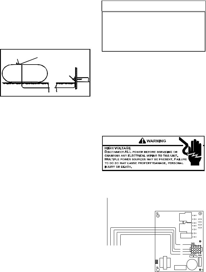
Low Voltage Wiring-*PG1360***1A Only
Refer to the unit wiring diagram for electrical connections. When installed, the unit must be electrically grounded in accordance with local codes or in the absence of local codes, with the National Electrical Code, ANSI/NFPA No. 70, and/or the CSA C22.1 Electrical Code. Ensure low voltage connections are waterproof.
 WARNING
TO AVOID THE RISK OF ELECTRICAL SHOCK, WIRING TO THE UNIT MUST BE POLARIZED AND GROUNDED.
 CAUTION
TO AVOID PROPERTY DAMAGE OR PERSONAL INJURY DUE TO FIRE, USE ONLY COPPER CONDUCTORS.
 CAUTION
TO PREVENT IMPROPER AND DANGEROUS OPERATION DUE TO WIRING ERRORS, LABEL ALL WIRES PRIOR TO DISCONNECTION WHEN SERVICING CONTROLS. VERIFY PROPER OPERATION AFTER SERVICING.
For unit protection, use a fuse or HACR circuit breaker that is in excess of the circuit ampacity, but less than or equal to the maximum overcurrent protection device. DO NOT EXCEED THE MAXIMUM OVERCURRENT DEVICE SIZE SHOWN ON UNIT DATA PLATE.
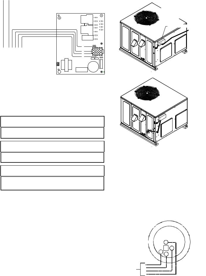
All line voltage connections must be made through weatherproof fittings. All exterior power supply and ground wiring must be in approved weatherproof conduit. Low voltage wiring from the unit control panel to the thermostat requires coded cable. See below for ground level and rooftop wiring.
Note:Junction box location shown is optional and is
for illustration purposes only.
JUNCTION BOX
Electrical Power Directly To Junction Box
Electrical Power Routed Through Bottom of Unit
Typical Electrical Wiring Unit Voltage
UNIT VOLTAGE
The unit transformer is factory connected for 230V operation. If the unit is to operate on 208V, reconnect the transformer primary lead as shown on the unit wiring diagram. The induced draft blower on some models is equipped with a 230V lead (red) and a 208V lead (black). If equipped, connect the induced draft blower 208V lead (black) in place of the 230V lead (red). Tape the unused 230V lead.
HEAT ANTICIPATOR SETTING
The heat anticipator is to be set by measuring the load (amperage) at the “R” circuit. Follow the instructions provided by the thermostat for more details.
G
Y
R
W |
R
From W
Unit Y
G
Typical Thermostat and Unit 24 V Wiring Hookup
9
Y/Y2
G
Y
R
W |
Y/Y2 |
R
From W
Unit Y1
G
Typical 2-Stage Cool Thermostat and
Unit 24 V Wiring Hookup
*PG1360***1A Only
CIRCULATING AIR AND FILTERS
AIRFLOW CONVERSION
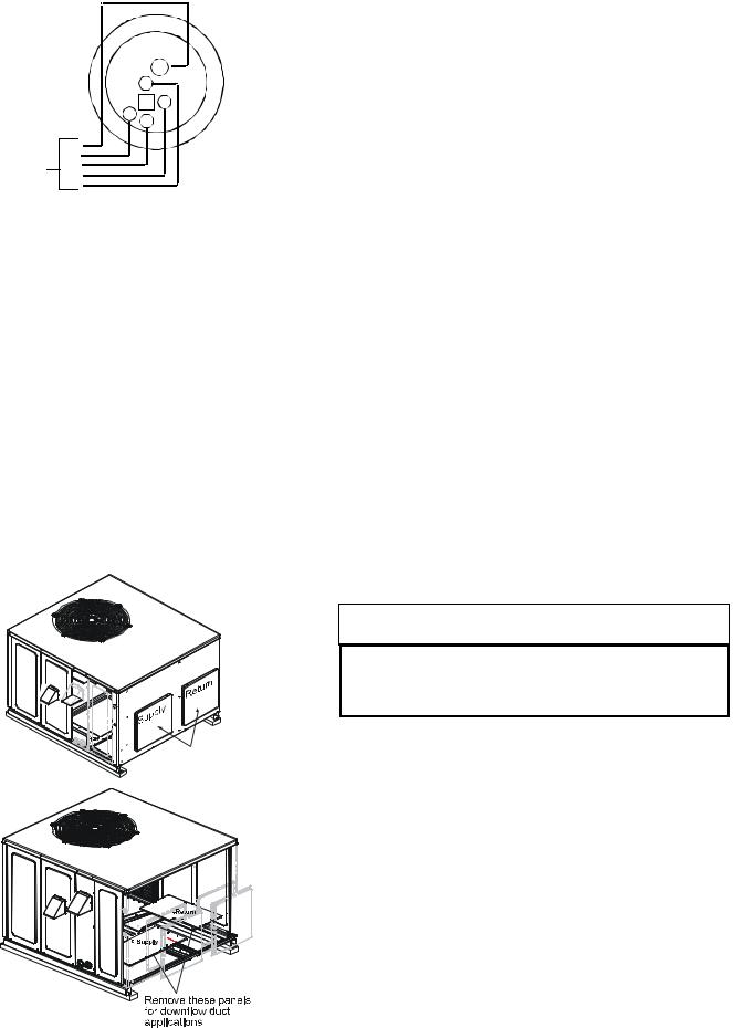
Units can easily be converted from horizontal to downdischarge airflow delivery. In down-discharge or high static installations, the installer should measure the total external static and review the blower performance charts before performing the installation. In some installations it will be necessary to change the blower speed to provide proper air flow.
Horizontal Air Flow (Applies to 3 phase models)
Single phase models are shipped without horizontal duct covers. If needed, these kits may be ordered through Goodman’s Service Parts department.
Remove supply and return duct covers which are attached to the unit as shown below.
Remove these covers for horizontal duct applications
Duct Cover Installation
Down Discharge Applications
Cut insulation around bottom openings and remove panels from the bottom of the unit, saving the screws holding the panels in place.
NOTE: Single phase models require installation of horizontal duct kit #20464501PDGK (medium chassis) and #20464502PDGK (large chassis).
DUCTWORK
Duct systems and register sizes must be properly designed for the C.F.M. and external static pressure rating of the unit. Ductwork should be designed in accordance with the recommended methods of Air Conditioning Contractors of America Manual D (Residential) or Manual Q (Commercial). All ductwork exposed to the outdoors must include a weatherproof barrier and adequate insulation.
A duct system should be installed in accordance with Standards of the National Board of Fire Underwriters for the Installation of Air Conditioning, Warm Air Heating and Ventilating Systems. Pamphlets No. 90A and 90B.
The supply duct from the unit through a wall may be installed without clearance. However, minimum unit clearances as shown in the appendix must be maintained. The supply duct should be provided with an access panel large enough to inspect the air chamber downstream of the heat exchanger. A cover should be tightly attached to prevent air leaks.
For duct flange dimensions on the unit refer to the Unit Dimension illustration in the appendix.
For down-discharge applications, the ductwork should be attached to the roof curb prior to installing the unit. Ductwork dimensions are shown in the roof curb installation manual.
If desired, supply and return duct connections to the unit may be made with flexible connections to reduce possible unit operating sound transmission.
FILTERS
 CAUTION
TO PREVENT PROPERTY DAMAGE DUE TO FIRE AND LOSS OF EQUIPMENT EFFICIENCY OR EQUIPMENT DAMAGE DUE TO DUST AND LINT BUILD UP ON INTERNAL PARTS, NEVER OPERATE UNIT WITHOUT AN AIR FILTER INSTALLED IN THE RETURN AIR SYSTEM.
Even though a return air filter is not supplied with this unit, there must be a means of filtering all return air. The *PG1336(3A,4A), *PG1342, *PG1348, and *PG1360 models are provided with internal filter racks for down-discharge applications. All units may be externally filtered.
Refer to the unit filter size chart in the appendix for filter size information.
Filters installed external to the unit should be sized in accordance with their manufacturer recommendations. A throwaway filter must be sized for a maximum face velocity of 300 feet per minute.
Filter Installation
Important: When installing a filter, the air flow arrows on the filter must point toward the circulator blower.
10
VENTING
NOTE: Venting is self-contained. Do not modify or block.
FLUE HOOD INSTALLATION
Install the flue hood and bug screen prior to operation of the unit.
To install the flue hood cover and bug screen:
1.Remove the flue hood and bug screen from inside the heat exchanger compartment.
2.Slide the bug screen over the flanges of the flue hood and attach the flue hood and screen to the unit with the sheet metal screws provided.
Flue Hood and Bug Screen Installation
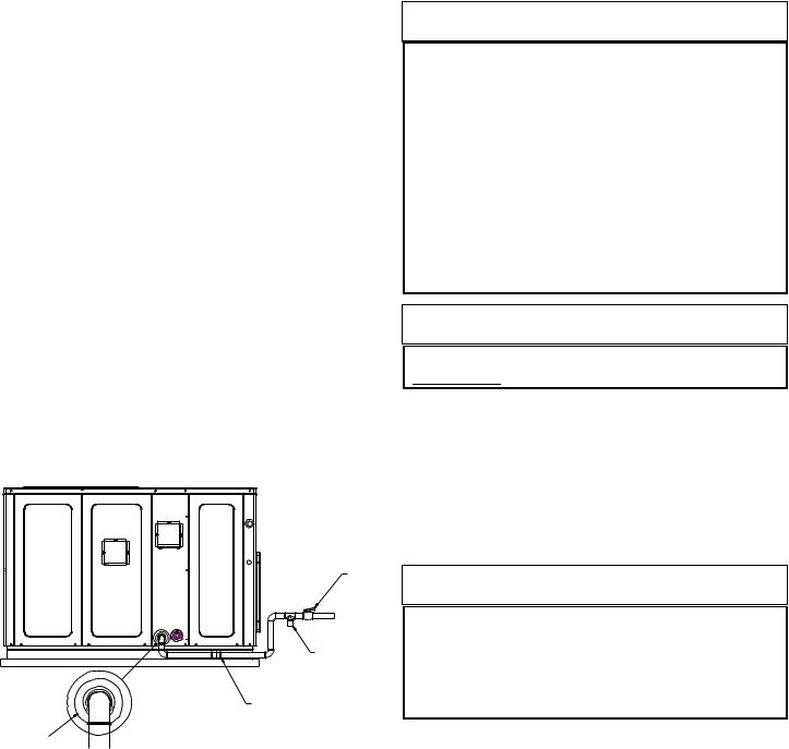
CONDENSATE DRAIN
CONDENSATE DRAIN CONNECTION
A 3/4” NPT drain connection is supplied for condensate piping. An external trap must be installed for proper condensate drainage.
DRAIN CONNECTION
UNIT |
2" MINIMUM |
FLEXIBLE |
|
TUBING-HOSE |
3" MINIMUM |
OR PIPE |
|
A POSITIVE LIQUID
SEAL IS REQUIRED
Drain Connection
NORMAL SEQUENCES OF OPERATION
HEATING
This unit is equipped with an ignition control that automatically lights the main burner. DO NOT attempt to light the main burners by any other method.
1.Thermostat calls for heat. The induced draft blower energizes for a 15-second pre-purge.
2.The spark igniter and gas valve energizes for 7 seconds. NOTE: The igniter produces a very intense electrical spark that ignites the gas.
3.The 30-second HEAT FAN ON delay time begins. *PG13(48,60)***1A ONLY: Heat on delay begins when thermostat calls for heat. ECM motor is energized approximately 45 seconds later. NOTE: ECM motor may operate at approximately 100 CFM or less during the 45 second on delay period. ECM motor will energize at heating speed after the 45 second delay regardless of the status of the main burner flame.
4.The unit delivers heat to the conditioned space until the thermostat is satisfied.
5.The gas valve deenergizes. The induced draft blower continues operation for a 29-second post-purge.
6.Ignition control begins timing the HEAT FAN OFF delay. There is an adjustable HEAT FAN OFF delay of approximately 120/135/150 seconds (factory set at 150). After the HEAT FAN OFF delay time has elapsed, the blower will deenergize. This allows any additional heat in the heat exchanger to be transferred to the conditioned space. *PG13(48,60)***1A ONLY: HEAT FAN OFF delay is fixed at 180 seconds. Airflow level is 50% of nominal heating airflow.
COOLING
1.Thermostat calls for cooling. The compressor and outdoor fan are energized.
2.Approximately seven seconds later, the indoor fan starts.
3.The unit will deliver cooling to the conditioned space until the thermostat is satisfied.
4.The compressor and outdoor fan will be deenergized when the thermostat opens.
5.The indoor fan continues to run for approximately 60 seconds after the thermostat is satisfied. This allows
additional cooling from the indoor coil to be transferred to the conditioned space. Then, the indoor fan stops.
*PG1348***1A ONLY:
1.Thermostat calls for cooling. Outdoor fan and compressor are energized. ECM motor is energized almost immediately for 30 seconds at 50% of the nominal airflow. Airflow then increases to nominal airflow.
2.The unit will deliver cooling to the conditioned space until thermostat is statisfied.
3.The outdoor fan and compressor will be de-energized when thermostat opens.
4.ECM motor continues to operate for approximately 60 seconds at 50% of nominal airflow after thermostat opens.
*PG1360***1A ONLY:
1.Thermostat calls for low stage cooling. Outdoor fan and low stage compressor are energized. ECM motor is energized almost immediately for 30 seconds at 50% of the nominal low stage airflow. Airflow then increases to nominal low stage airflow.
If thermostat calls for high stage cooling, outdoor fan and low and high stage compressor is energized. ECM motor is energized almost immediately for 30 seconds at 50% of the nominal high stage airflow. Airflow then increases to nominal high stage airflow.
2.The unit will deliver cooling to the conditioned space until thermostat is satisfied.
3.The outdoor fan and low stage compressor (or low and high stage compressor) will be de-energized when thermostat opens.
4.ECM motor continues to operate for approximately 60 seconds at 50% of nominal low stage airflow (or high stage airflow if thermostat call was for high stage cooling) after thermostat opens.
11
NOTE: A 180-second anti-short cycle is integral to the control and prevents recycling of the compressor.
FAN ONLY
1.Thermostat calls for FAN ONLY by energizing “G”.
2.Approximately seven seconds later, the indoor fan starts.
3.The indoor fan continues to run for approximately 60 seconds after “G” is de-energized.
*PG13(48,60)***1A ONLY:
1.Thermostat calls for FAN ONLY by energizing “G”.
2.ECM motor is energized almost immediately at approximately 30% of the nominal high stage cooling airflow, depending on setting (see “Blower Speed Adjustment” section).
3.ECM is de-energized almost immediately after “G” is deenergized.
STARTUP, ADJUSTMENTS, AND CHECKS
HEATING STARTUP
This unit is equipped with an electronic ignition device to automatically light the main burners. It also has a power vent blower to exhaust combustion products.
On new installations, or if a major component has been replaced, the operation of the unit must be checked.
Check unit operation as outlined in the following instructions. If any sparking, odors, or unusual sounds are encountered, shut off electrical power and recheck for wiring errors, or obstructions in or near the blower motors. Duct covers must be removed before operating unit.
Heat Anticipator Setting
Set the heat anticipator on the room thermostat to 0.4 amps to obtain the proper number of heating cycles per hour and to prevent the room temperature from overshooting the room thermostat setting.
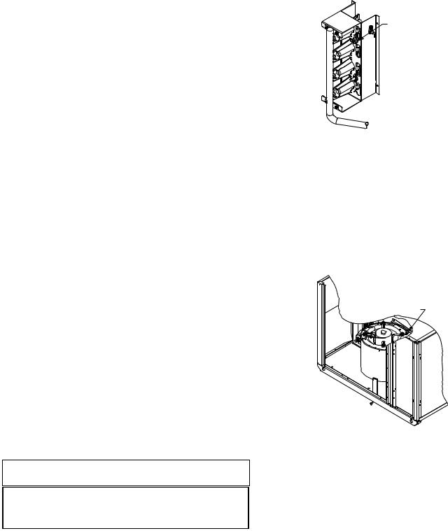
Rollout Protection Control
The rollout protection device opens, cutting power to the gas valve, if the flames from the burners are not properly drawn into the heat exchanger. The rollout protection device is located on the burner bracket. The reason for elevated temperatures at the control should be determined and repaired prior to resetting this manual reset control.
 WARNING
TO AVOID PROPERTY DAMAGE, PERSONAL INJURY OR DEATH DUE TO FIRE OR EXPLOSION, A QUALIFIED SERVICER MUST INVESTIGATE THE REASON FOR THE ROLLOUT PROTECTION DEVICE TO OPEN BEFORE MANUALLY RESETTING THE ROLLOUT PROTECTION DEVICE.
Rollout Protection
Rollout Protection on Burner Bracket
Secondary Limit Control
The secondary limit control is located on the top of the blower scroll assembly. This control opens when elevated temperatures are sensed. Elevated temperatures at the control are normally caused by blower failure. The reason for the opening should be determined and repaired prior to resetting.
If the power to the unit is interrupted during the heating cycle, it may cause the secondary limit to trip. Once the blower compartment temperature drops below the limit reset temperature, the limit will automatically reset.
Secondary
Control Limit
Back of Unit 
Secondary Limit Control
Pre-Operation Checks
1.Close the manual gas valve external to the unit.
2.Turn off the electrical power supply to the unit.
3.Set the room thermostat to its lowest possible setting.
4.Remove the heat exchanger door on the side of the unit by removing screws.
5.This unit is equipped with an ignition device which automatically lights the main burner. DO NOT try to light burner by any other method.
6.Move the gas control valve switch to the OFF position. Do not force.
7.Wait five minutes to clear out any gas.
8.Smell for gas, including near the ground. This is important because some types of gas are heavier than air. If you have waited five minutes and you do smell gas, immediately follow the warnings on page 3 of this manual.
12
 Loading...