


ADPF
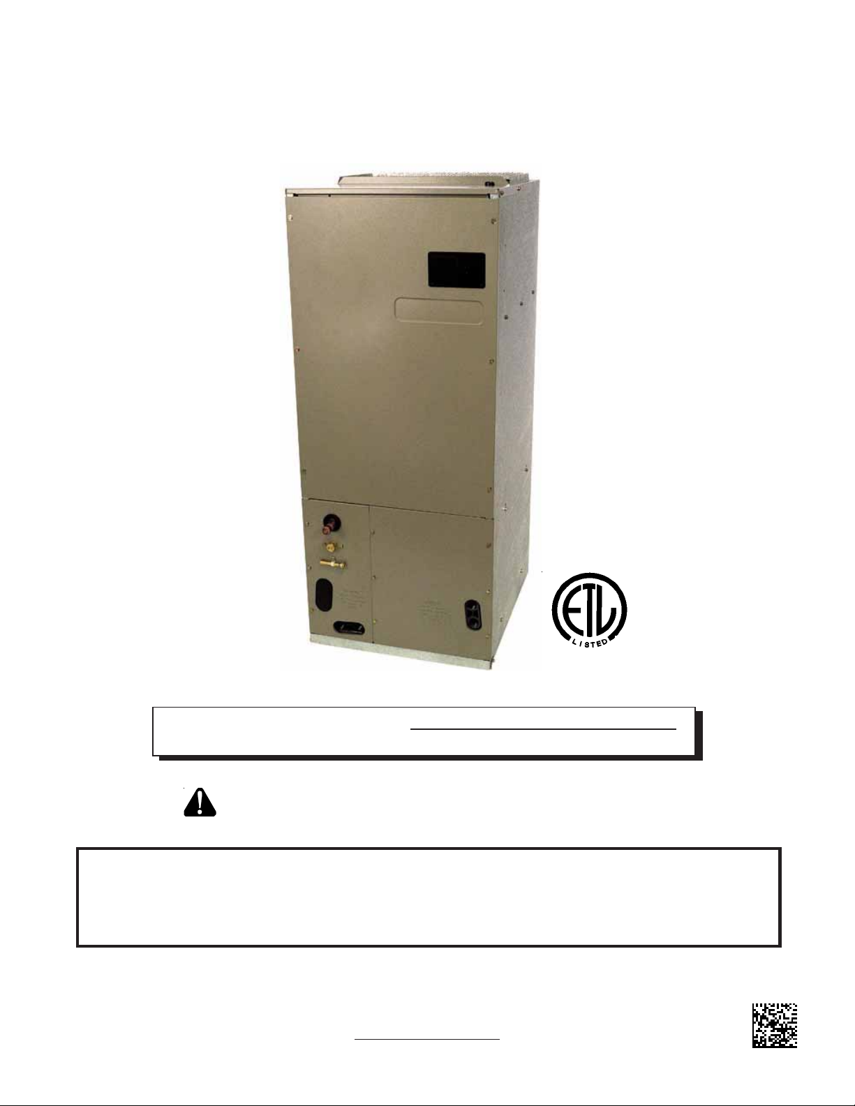
ATUF/ARUF/ARPF/ADPF/ASPF
AIR HANDLERS
INSTALLATION & OPERATING INSTRUCTIONS
IO-355E
08/10
®
C
US
NOTE: ATUF models are suitable for Upflow and Horizontal Installations only.
Do not use for Downflow Installations
RECOGNIZE THIS SYMBOL AS A SAFETY PRECAUTION.
ATTENTION INSTALLING PERSONNEL
Prior to installation, thoroughly familiarize yourself with this Installation Manual. Observe all safety warnings.
During installation or repair, caution is to be observed.
It is your responsibility to install the product safely and to educate the customer on its safe use.
Goodman Manufacturing Company, L.P.
5151 San Felipe, Suite 500, Houston, TX 77056
www.goodmanmfg.com
© 2004-2010 Goodman Manufacturing Company, L.P.
CONTENTS
Important Safety Instructions............................................. 2
Important Note to Owner Regarding Product Warranty..... 3
Shipping Inspection........................................................... 3
Codes & Regulations ........................................................ 3
Replacement Parts............................................................ 3
Pre-Installation Instructions ............................................... 3
Location............................................................................. 4
Ductwork ........................................................................... 4
Return Ductwork ............................................................... 4
Return Air Filters ............................................................... 4
Electric Heat...................................................................... 4
HKR Installation................................................................. 4
Electrical Supply Wire and MOP ....................................... 4
Building Electrical Service Inspection ............................... 5
Wire Sizing........................................................................ 5
Maximum Overcurrent Protection (MOP).......................... 6
Electrical Connections – Supply Voltage........................... 6
Air Handler Only (Non-Heat Kit Models)....................... 6
Air Handler With Non-Circuit Breaker Heat Kits ........... 6
Air Handler With Heat Kits
Containing a Circuit Breaker......................................... 6
Low Voltage Connections............................................. 6
Refrigerant Lines............................................................... 6
Tubing Preparation............................................................ 6
Post Brazing...................................................................... 6
Piping Size ........................................................................ 6
Special Instructions ........................................................... 6
Downflow Conversion ....................................................... 7
Horizontal Conversion ....................................................... 8
Condensate Removal........................................................ 8
ACHIEVING 2% LOW LEAKAGE RATE ........................... 9
ATUF/ARUF/ARPF/ADPF MOTOR ................................... 9
CFM Delivery .................................................................. 10
ASPF Motor..................................................................... 10
CFM Delivery .................................................................. 10
Thermostats .................................................................... 10
Start-Up Procedure ..........................................................11
Regular Maintenance .......................................................11
THERMOSTAT WIRING.................................................. 12
ASPF THERMOST AT CONNECTIONS........................... 14
COOLING UNIT WITH OPTIONAL HEAT KITS
OF 10kW AND BELOW.............................................. 14
COOLING UNIT WITH OPTIONAL HEAT KITS
OF 15 kW AND ABOVE AND
ROOM THERMOST AT
WITH TWO ST AGES OF HEAT.................................. 15
HEAT PUMP UNIT WITH OPTIONAL
HEAT KITS OF 10kW AND BELOW ........................... 15
HEAT PUMP UNIT WITH OPTIONAL
HEAT KITS OF 15 kW AND ABOVE ........................... 16
ELECTRONIC BLOWER TIME DELAY RELAY .............. 17
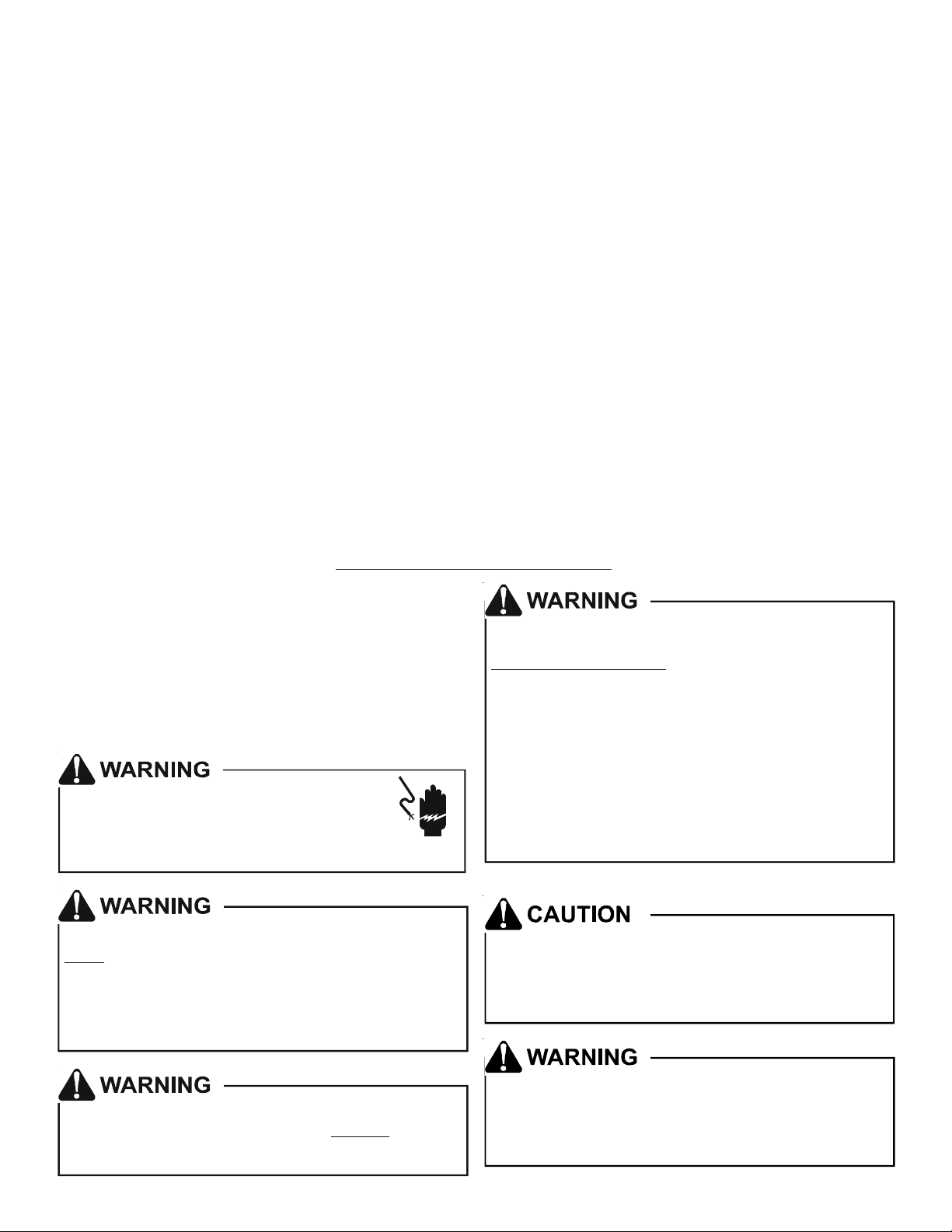
Important Safety Instructions
The following symbols and labels are used throughout this
manual to indicate immediate or potential safety hazards. It
is the owner’s and installer’s responsibility to read and comply with all safety information and instructions accompanying
these symbols. Failure to heed safety information increases
the risk of personal injury, property damage, and/or product
damage.
HIGH VOLTAGE!
Disconnect ALL power before servicing.
Multiple power sources may be present.
Failure to do so may cause property dama ge,
personal injury or de ath.
Install ati on an d re pair of t his u ni t sho uld b e p erf orm ed
by indiv id uals me et ing t he requi re men ts of an
ONLY
“entry level technician” as specified by
the Ai r-Co ndi ti on in g, H eati ng a nd Re fri g erati on I nst i tu te
(AHRI). Attempting to install or repair this unit without
such ba ck grou nd may re sul t i n p r od uct damag e,
personal inju ry or death.
, at a minimum,
To avoid property damage, personal injury or death
due to electrical shock, this unit MUST have an
uninterrupted, unbroken
electrical ground circuit may consist of an
appropriately sized electrical wire connecting the
ground lug in the unit control box to the building
electrical service panel.
Other meth ods of gro unding are permit ted i f pe rfo rmed
in accordance with the National Electric Code
(NEC) /Amer ican National Stan dard s Inst itut e
(ANSI)/ Nati onal Fire P rotec tion Assoc iation (NFP A) 70
and local /s ta te c ode s. I n Canad a, e lect ri ca l gro unding
is to be in accordance wit h t he C ana di an El ec tri c Code
(CSA) C22.1.
When installing or servicing this equipment, safety
clothing, including hand and eye protection, is
strongly recommended. If installing in an area that has
special safety r equirements (har d hats, etc.), Observe
these requirements.
electrical ground. The
This product is factory-shipped for use with
208/240/1/60 electrical power supply.
reconfigure this air handler to operate with any ot her
power supply.
DO NOT
Do not connect to or use any device that is not des igncertified by Goodman for use with this unit. Serious
property damage, personal injury, reduced unit
performance and/or hazardous conditions may result
from the use of such non-approved devices.
2
To prevent the risk of property damage, personal
injury , or dea th, do not store comb ustible m aterials or
use gasoline or other flammable liquids or vapors in
the vicin ity of this unit.
Product limited warranty certificates for models currently in
production can be viewed at
www.goodmanmfg.com or
www.amana-hac.com. If your model is not currently in production or does not appear on the website, please contact
your installing contractor or contact customer service (877254-4729) to obtain a copy of your warranty certificate.
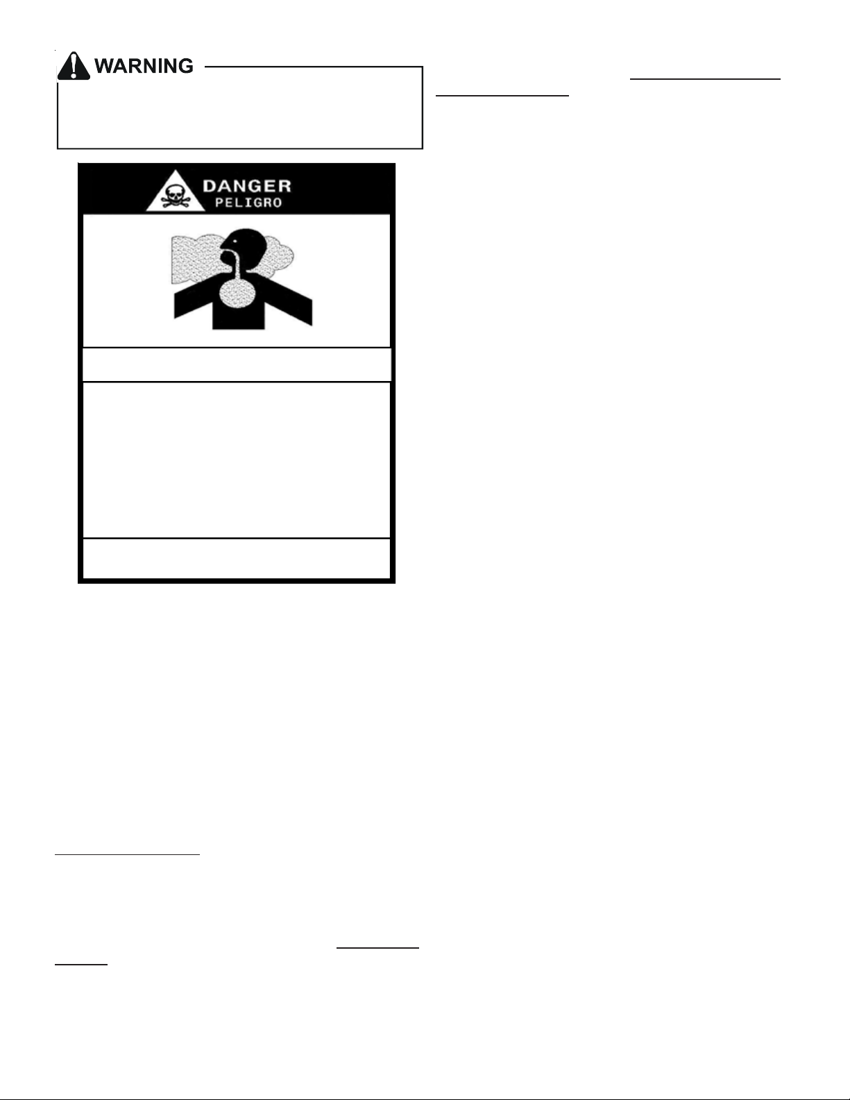
CARBON MONOX IDE POISON ING HAZ ARD
Special Warning for Installation of Furnace or Air Handling Units in
Enclosed Areas such as Garages, Utility Rooms or Parking Areas
Carbon monoxide producing devices (such as an automobile, space
heater, gas water heater, etc.) should not be operated in enclosed areas
such as unventilated garages, utility rooms or parking areas because of
the danger of carbon monoxide (CO) poisoning resulting from the exhaust
emissions. If a furnace or air handler is installed in an enclosed area such
as a garage, utility room or parking area and a carbon monoxide producing
device is operated therein, there must be adequate, direct outside
ventilation.
This ventilation is necessary to avoid the danger of CO poisoning which
can occur if a carbon monoxide producing device continues to operate in
the enclosed area. Carbon monoxide emissions can be (re)circulated
throughout the structure if the furnace or air handler is operating in any
mode.
CO can cause serious illness including permanent brain damage or death.
B10259-216
-
Important Note to the Owner regarding Product
Warranty
Your warranty certificate is supplied as a separate document
with the unit installed by your contractor. Read the limited
warranty certificate carefully to determine what is and is not
covered and keep the warranty certificate in a safe place. If
you are unable to locate the warranty certificate please contact your installing contractor or contact customer service
(877-254-4729) to obtain a copy.
To receive the 10 Year Parts Limited Warranty, online registration must be completed within 60 days of installation.
Online registration is not required in California or Quebec.
To register your Goodman® brand unit, go to
www.goodmanmfg.com. Click on the word “Warranty” located on the left side of the home page. Next, click on the
word “Product Registration” located on the left side of the
Warranty page and complete the forms in the manner indicated on the Product Registration page.
To register your Amana® brand unit, go to www.amanahac.com. Click on the word “Warranty” located on the top
right of the home page. Next, click on the word “Product
Registration” located on the left side of the Warranty page
and complete the forms in the manner indicated on the Product Registration page.
Each product overview page contains a Product Warranty
link; by clicking on it you will be able to view the limited warranty coverage for that specific product. To view warranty
registration information, click on the Product Warranty text
on the left navigation panel on the home page of each website. The Online Product Registration pages are located in
this same section.
Keep this literature in a safe place for future reference.
Shipping Inspection
Always keep the unit upright; laying the unit on its side or top
may cause equipment damage. Shipping damage, and subsequent investigation is the responsibility of the carrier. Verify
the model number, specifications, electrical characteristics,
and accessories are correct prior to installation. The distributor or manufacturer will not accept claims from dealers for
transportation damage or installation of incorrectly shipped
units.
Codes & Regulations
This product is designed and manufactured to comply with
national codes. Installation in accordance with such codes
and/or prevailing local codes/regulations is the responsibility of the installer. The manufacturer assumes no responsibility for equipment installed in violation of any codes or regulations.
The United States Environmental Protection Agency
(EPA) has issued various regulations regarding the introduction and disposal of refrigerants. Failure to follow
these regulations may harm the environment and can
lead to the imposition of substantial fines. Should you
have any questions please contact the local office of the EPA.
Replacement Parts
When reporting shortages or damages, or ordering repair
parts, give the complete product model and serial numbers
as stamped on the product. Replacement parts for this product are available through your contractor or local distributor.
For the location of your nearest distributor consult the white
business pages, the yellow page section of the local telephone book or contact:
SERVICE PARTS DEPARTMENT
GOODMAN MANUFACTURING COMPANY, L.P.
5151 SAN FELIPE, SUITE 500
HOUSTON, TEXAS 77056
(713) 861 – 2500
If replacing an air handler, the system must be manufacturer
approved and Air-Conditioning, Heating, and Refrigeration
Institute (AHRI) matched. NOTE: Installation of unmatched
systems is strongly discouraged.
3

Pre-Installation Instructions
Carefully read all instructions for the installation prior to installing product. Make sure each step or procedure is understood and any special considerations are taken into account
before starting installation. Assemble all tools, hardware
and supplies needed to complete the installation. Some items
may need to be purchased locally. Make sure everything
needed to install the product is on hand before starting.
Location
NOTE: Air handlers are designed for indoor installation
only.
Give special consideration to minimizing the length of refrig-
erant tubing when installing air handlers. Refer to Remote
Cooling/Heat Pump Service Manual, TP-106 Long Line Set
Application R-22 or TP-107 Long Line Set Application R-410A
for guidelines. The unit clearance from a combustible surface may be 0". However, service clearance is to take precedence. In addition allow a minimum of 24" in front of the unit
for service clearance.
Do not install the air handler in a location that violates the
instructions provided with the condenser.
If the unit is located in an area with high ambient temperature
and/or high humidity the air handler maybe subject to nuisance sweating of the casing. On these installations a wrap
of 2” fiberglass insulation with a vapor barrier is recommended.
Consult all appropriate regulatory codes prior to determining
final clearances. When installing this unit in an area that may
become wet, elevate the unit with a sturdy, non-porous material. In installations that may lead to physical damage (i.e. a
garage) it is advised to install a protective barrier to prevent
such damage.
Ductwork
This air handler is designed for a complete supply and return
ductwork system.
Do not operate this product without all the ductwork
attached.
To ensure correct system performance, the ductwork is to be
sized to accommodate 375-425 CFM per ton of cooling with
the static pressure not to exceed .5" WC. Inadequate duct
work that restricts airflow can result in improper performance
and compressor or heater failure. Ductwork is to be constructed in a manner that limits restrictions and maintains
suitable air velocity. Ductwork is to be sealed to the unit in a
manner that will prevent leakage.
Return Ductwork
DO NOT TERMINATE THE RETURN DUCTWORK IN AN
AREA THAT CAN INTRODUCE TOXIC, OR OBJECTIONABLE FUMES/ODORS INTO THE DUCTWORK. The return
ductwork is to be introduced into the air handler bottom (upflow
configuration).
Return Air Filters
Each installation must include a return air filter. This filtering
may be performed at the air handler or externally such as a
return air filter grille. Air handlers mounted in the downflow
orientation, including “B” series, require external filtering. A
washable filter is available as an accessory. To ensure optimum performance frequent filter cleaning is advised. Refer
to Table 1 for the appropriate filter.
ATUF
ARUF
ARPF
1 824 1824 N/A FIL 18- 32
1729
1824
ADPF ASPF
Filter
Number
Qty
Required
1
3030 3030
1931 1931
3030 1830 FIL 36-42 1
3636 3636
3642 3642 3042 3036
3743 3743 3137
FIL 48 -6 1 1
4860 4860 4860 4260
Table 1
Electric Heat
Refer to this manual in combination with the instructions provided with the heat kit for the correct installation procedure.
The air handlers listed in this manual do not have factory
installed electric heat. Electric heat is available as an accessory. If installing this option, the ONLY heat kits that can be
used are the HKR series.
NOTE: The Amana® brand EHK, ECB, EDB, and EDK kits
are NOT approved for use with these air handlers.
The heating mode temperature rise is dependent upon the
system airflow, the supply voltage, and the heat kit size (kW)
selected. Use Tables 2, 3, and 4 to determine the temperature rise (ºF).
CFM
356810152021
600 18 28 35 41
800 13 21 26 31 42
1000 11 17 21 25 34 50
12009 14182128425662
14008 12151824364853
16007 10131521314246
1800 6 9 12 14 19 28 37 41
2000 5 8 11 12 17 25 34 37
230/1/60 Supply Voltage - Temperature Rise Table °F
CFM
600 17 27 34 39
800 13 20 25 30 40
1000 10 16 20 24 32 48
12008 13172027405359
14007 11141723344651
16006 10131520304044
1800 6 9 11 13 18 27 36 39
2000 5 8 10 12 16 24 32 35
356810152021
220/1/60 Supply Voltage - Temperature Rise Table °F
4
HEAT KIT NOMINAL kW
Table 2
HEAT KIT NOMINAL kW
Table 3
CFM
600 16 25 32 37
800 12 19 24 38 38
1000 10 15 19 22 30 46
12008 13161925385156
14007 11141622334348
1600 6 9 12 14 19 28 38 42
1800 5 8 11 12 17 25 34 37
2000 5 8 10 11 15 23 30 34
356810152021
208/1/60 Supply Voltage - Temperature Rise Table °F
HEAT KIT NOMINAL kW
Table 4
NOTE: For installations not indicated above the following
formula is to be used:
TR = (kW x 3412) x (Voltage Correction) x 1.08 / CFM
Where: TR = Temperature Rise
kW = Heater Kit Actual kW
3412 = Btu per kW
Voltage Correction =.96 (230 Supply Volts)
=.92 (220 Supply Volts)
=.87 (208 Supply Volts)
1.08 = Constant
CFM = Measured Airflow
NOTE: The Temperature Rise Tables can also be used to
determine the air handler airflow delivery. When using these
tables for this purpose set the room thermostat to maximum
heat and allow the system to reach steady state conditions.
Insert two thermometers, one in the return air and one in the
supply air. The temperature rise is the supply air temperature
minus the room air temperature.
Use HKR specification sheets to determine the HKR available for a given air handler.
HKR Installation
Follow instructions listed in Installation and Operating Instructions shipped with the heat kit.
Electrical Supply Wire and MOP
FIRE HAZARD!
To avoid the risk of property da mage, personal injury
or fire, use only copper conductors.
HIGH VOLTAGE!
Disconnect ALL power before servicing.
Multiple power sources may be present.
Failure to do so may cause property dama ge,
personal injury or de ath.
HIGH VOLTAGE!
T o avoid prope rty dama ge , persona l injury or death
due to el ect rical shock, th is u ni t MU ST have an
uninterrupted, unbroken
electrical ground. The
electrical ground circuit may consist of an
appro pri at ely sized electrical wire connecting the
ground lug in the unit control box to the building
electrical service panel.
Other methods of grounding are permit ted if perform ed
in accordance with the National Electric Code
(NEC) /Americ an Nation al Standar ds Institut e
(ANSI)/National Fire Protection Association (NFP A) 70
and local/state codes. In Canada, electrical grounding
is to be in ac co rda nce w ith th e C ana dian Elec tric Cod e
(CSA) C22.1.
Building Electrical Service Inspection
This unit is designed for single-phase electrical supply. DO
NOT OPERATE ON A THREE-PHASE POWER SUPPLY.
Measure the power supply to the unit. The supply voltage
must be in agreement with the unit nameplate power requirements and within the range shown in Table 5.
Nominal Input Minimum Voltage Maximum Voltage
208/240 187 253
Table 5
Wire Sizing
Wire size is important to the operation of your equipment.
Use the following check list when selecting the appropriate
wire size for your unit.
• Wire size must carry the Minimum Circuit Ampac-
ity (MCA).
• Refer to the NEC (USA) or CSA (Canada) for wire sizing. The unit MCA for the air handler and the optional
electric heat kit can be found on the unit Series and
Rating Plate.
• Wire size allows for no more than a 2% voltage drop
from the building breaker/fuse panel to the unit.
Refer to the latest edition of the National Electric Code
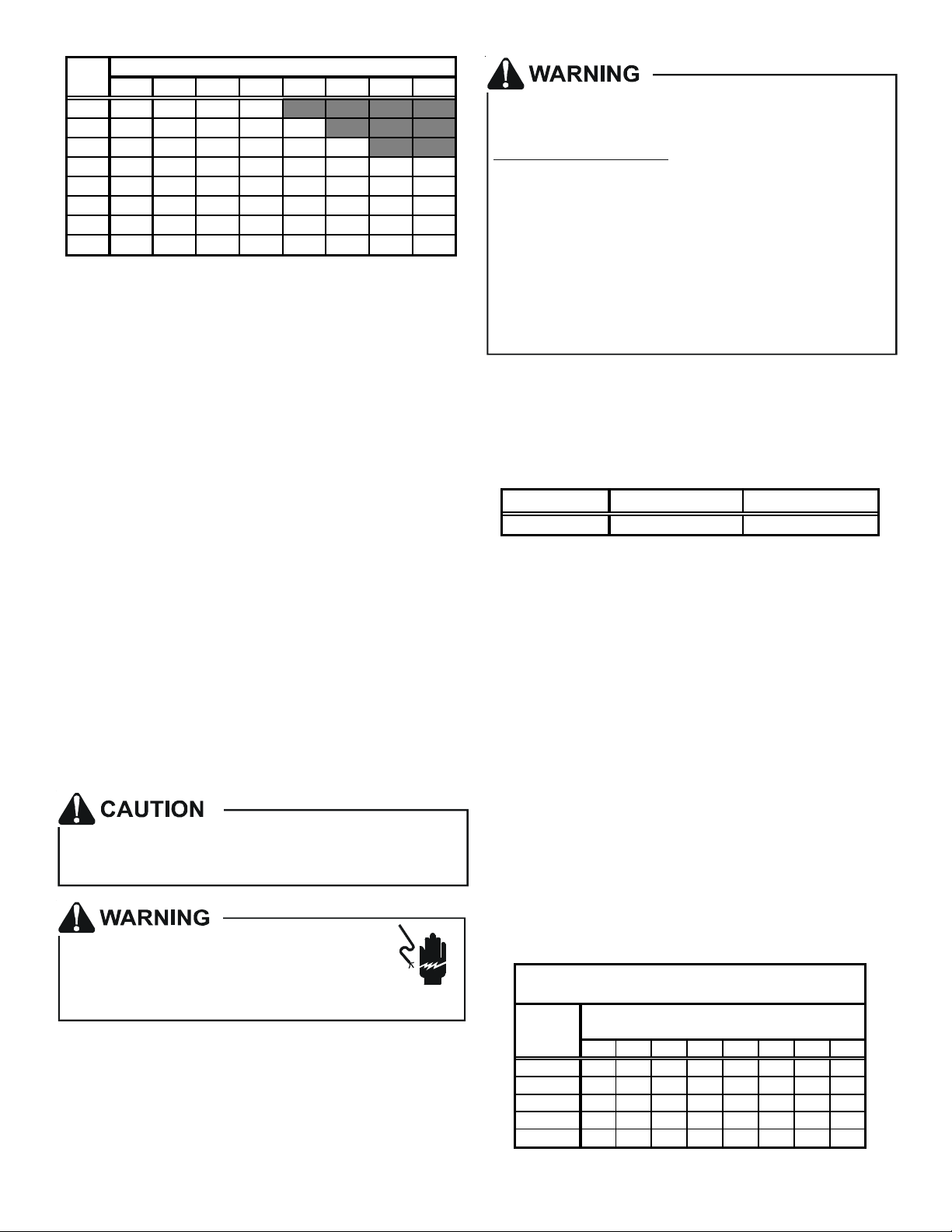
or in Canada the Canadian Electric Code when determining the correct wire size. The following table shows
the current carrying capabilities for copper conductors
rated at 75oC with a 2% voltage drop. Use Table 6 to
determine the voltage drop per foot of various conductors.
Maximum Allowable Length in Feet
to Limit Voltage Drop to 2%*
Wire Size
(AWG)
14 75 50 37 NR NR NR NR NR
12 118 79 59 47 NR NR NR NR
10 188 125 95 75 63 54 NR NR
8 301 201 150 120 100 86 75 68
6 471 314 235 188 157 134 118 110
*Based on NEC 1996
Minimum Circuit Ampacity (MCA)
10 15 20 25 30 35 40 45
Table 6
5
Maximum Overcurrent Protection (MOP)
Every installation must include an NEC (USA) or CEC
(Canada) approved overcurrent protection device. Also,
check with local or state codes for any special regional requirements.
Protection can be in the form of fusing or HACR style circuit
breakers. The Series and Rating Plate can be used as a
guide for selecting the MAXIMUM overcurrent device.
NOTE: Fuses or circuit breakers are to be sized larger
than the equipment MCA but not to exceed the MOP.
Electrical Connections – Supply Voltage
USE COPPER CONDUCTORS ONLY.
A knockout is provided on the air handler top panel or side to
allow for the entry of the supply voltage conductors. If the
knockouts on the cabinet sides are used for electrical conduit, an adapter ring must be used in order to meet UL1995
safety requirements. An NEC or CEC approved strain relief
is to be used at this entry point. The wire is to be sized in
accordance with the “Electrical Wire and MOP” section of
this manual. Some areas require the supply wire to be enclosed in conduit. Consult your local codes.
Air Handler Only (Non-Heat Kit Models)
The building supply connects to the stripped black and red
wires contained in the air handler electrical compartment cavity. A ground screw is also contained in this area. Attach the
supply wires to the air handler conductors as shown in the
unit wiring diagram using appropriately sized solderless connectors or other NEC or CEC approved means.
Air Handler With Non-Circuit Breaker Heat Kits
A terminal block is provided with the HKR kit to attach the
power supply and air handler connections. Follow the HKR
Installation Manual and wiring diagram for complete wiring
details.
Air Handler With Heat Kits Containing a Circuit Breaker
HKR models with a “C” suffix contain a circuit breaker(s).
The air handler has a plastic cover on the access panel that
will require either one or both sections to be removed to allow the heat kit circuit breaker(s) to be installed. See the
HKR Installation Instructions for further details. The air handler wires and supply wires are installed directly onto the HKR
circuit breaker(s) as shown in the HKR Installation Manual
and wiring diagram.
Low Voltage Connections
Several combinations of low voltage schemes are available,
depending on the presence of a heat kit and whether the
heat kit is single-stage or multi-staging. The low voltage connections are determined by whether the outdoor unit is a condenser or heat pump. The 24V-control voltage connects the
air handler to the room thermostat and condenser. Low voltage wiring is to be copper conductors. A minimum of 18AWG
must be used for installations up to 50’ and 16AWG for installations over 50’. Low voltage wiring can be connected
through the top of the cabinet or either side. See the “Thermostat Wiring” section of this manual for typical low voltage
wiring connections.
Refrigerant Lines
This product is factory-shipped under pressure. Follow
these instructions to prevent injury.
A quenc hing c loth is strongly recomme nde d to preven t
scorching or marring of the equipmen t finish when
welding cl o s e t o th e p ain t ed surfaces. Us e b ra z in g
alloy of 5% minimum silver content.
Tubing Preparation
All cut ends are to be round, burr free, and clean.
Failure to follow this practice increases the chances for
refrigerant leaks. The suction line is spun closed and
requires pipe cutters to remove the closed end.
Post Brazing
Quench all welded joints with water or a wet rag.
Piping Size
For the correct tubing size, follow the specification
for the condenser/heat pump.
CAUTION
Applying too much heat to any tube can melt the tube. Torch
heat required to braze tubes of various sizes must be
proportiona l to the s ize of th e tub e. S erv ice p ersonn el m u st
use the appropriate heat level for the size of the tube being
brazed.
Special Instructions
This coil comes equipped with a check style flowrator for refrigerant management. For most installations with matching
applications, no change to the flowrator piston is required.
However, in mix-matched applications, a flowrator piston
change may be required. See the Goodman® piston kit chart
or consult your local distributor for details regarding mixmatched piston sizing. If the mix-match application requires
a different piston size, change the piston in the flowrator on
the indoor coil before installing the coil and follow the procedure shown below.
IMPORTANT NOTE: Torch heat required to braze tubes of
various sizes is proportional to the size of the tube. Tubes of
smaller size require less heat to bring the tube to brazing
temperature before adding brazing alloy. Applying too much
heat to any tube can melt the tube. Service personnel must
use the appropriate heat level for the size of the tube being
brazed.
NOTE: The use of a heat shield when brazing is recommended
to avoid burning the serial plate or the finish on the unit. Heat
trap or wet rags should be used to protect heat sensitive
components such as service valves and TXV valves.
1. Loosen the 13/16 nut 1 TURN ONLY to allow high pressure tracer gas to escape. No gas indicates a possible
leak.
6
 Loading...