

Page 1
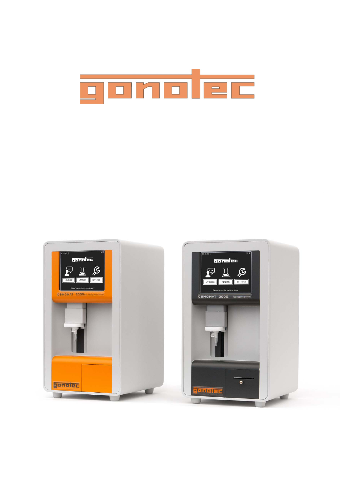
User Guide
OSMOMAT 3000basic OSMOMAT 3000
Version 1.22 1/6/2016
Page 2

Gonotec GmbH
GSG-Hof Reuchlinstr. 10-11
10553 Berlin
Germany
Original Device Documentation
Phone: (030) 7809 588-0
Fax: (030) 7809 588-88
E-mail: [email protected]
Web: http://www.gonotec.com
WEEE reg. no.: DE65424410
© 2014-2016
2 Version 1.22 1/6/2016
Page 3

This manual allows for the saf e and eff icient operatio n of the
OSMOMAT 3000 (hereafter "device"). This manual is part of the
device and must be stored in the immediate vicinity of the device
and
Personnel must
beginning any kind of work. Compliance with the safety notices and
instructions in this manual is the basis for a safe work environment.
In
provisions for the intended use of the device must be followed.
Figures in this manual are included for basic understanding and may
differ from the actual application.
Other applicable documents
In addition to this manual, the documents included with
documentation apply. The warnings
in
Copyright
The contents of this manual are protected by copyright. Their use is
permitted in connection with the use of this device.
this scope is not permitted without prior written authorization from
Gonotec GmbH.
Manufacturer contact info
be easily accessible to personn el at an y tim e.
carefully read and understand this manual before
addition, local accident prevention regulations and general safety
the device
– in particular safety notices –
this documentation must be observed!
Any use beyond
Address Gonotec GmbH
GSG-Hof Reuchlinstr. 10-11
10553 Berlin
Germany
Phone (030) 7809 588-0
Toll-free support hotline: 0800-7846027
(Germany only)
Version 1.22 1/6/2016 3
Page 4

4 Version 1.22 1/6/2016
Page 5

OSMOMAT 3000basic // OSMOMAT 3000
Table of Contents
Table of Contents
Table of Contents ........................................................................... 5
1 Overview ................................................................................. 9
2 Safety ..................................................................................... 13
2.1 Explanation of symbols ....................................................13
2.2 Intended use .....................................................................15
2.3 Additional hazards ............................................................15
2.3.1 Hazards due to electrical current ......................15
2.3.2 Risk of infection ................................................16
2.3.3 Risk of injury .....................................................16
2.3.4 Risks of device damage ...................................17
2.3.5 Reproducibility of the measurement .................18
2.4 Operator responsibilities ...................................................19
2.5 Personnel requirements ...................................................21
2.6 Personal safety gear ........................................................22
2.7 Environmental protection ..................................................22
3 Design and function ............................................................. 23
3.1 Device overview ...............................................................23
3.2 Measuring method basics ................................................27
3.3 Measurement equipment ..................................................28
3.4 Touchscreen .....................................................................30
3.5 Printer (does not apply to OSMOMAT 3000basic) ..............32
3.6 Connections and interfaces (does not apply to
OSMOMAT 3000basic) .......................................................33
3.6.1 Interface configuration ......................................34
3.6.2 Log formats ......................................................35
3.6.3 Data transfer.....................................................35
3.6.4 General options ................................................35
3.6.5 CSV format .......................................................36
3.6.6 XML format .......................................................37
3.6.7 Legacy CSV format ..........................................39
3.6.8 Error messages ................................................40
3.6.9 Checksums.......................................................40
4 Delivery, packaging, and storage ....................................... 41
4.1 Packaging .........................................................................42
4.2 Device storage .................................................................44
4.3 Unpack device ..................................................................44
5 Installation ............................................................................ 45
5.1 Transport device inside lab ..............................................45
5.2 Install device .....................................................................46
5.3 Connect device .................................................................47
Version 1.22 1/6/2016 5
Page 6

OSMOMAT 3000basic // OSMOMAT 3000
Table of Contents
6 Setup ..................................................................................... 48
6.1 Check printer (Option D) (does not apply to
OSMOMAT 3000basic) ...................................................... 48
6.2 Check free movement of steel needle ............................. 48
6.3 Set calibration defaults .................................................... 49
6.4 Date Time ........................................................................ 51
6.5 Measurement series name .............................................. 51
6.6 Result Unit ....................................................................... 51
7 Operation .............................................................................. 52
7.1 Power up device .............................................................. 53
7.2 Modify user preferences .................................................. 54
7.3 Measure individual samples ............................................ 57
7.4 Batch/series measurement (does not apply to
OSMOMAT 3000basic) ...................................................... 61
7.5 Calibrate device ............................................................... 65
7.6 Power down device ......................................................... 71
8 Troubleshooting ................................................................... 72
8.1 Safety notices .................................................................. 72
8.2 Notes regarding errors..................................................... 73
8.3 Error table ........................................................................ 74
8.4 Resolve errors ................................................................. 78
8.4.1 Replace cryst-needle ....................................... 78
8.4.2 Replace the temperature sensor ..................... 82
8.4.3 Replace microfuses ......................................... 89
8.4.4 Clean cooling clamp ........................................ 90
8.4.5 Replace printer paper (Option D only)
(does not apply to OSMOMAT 3000basic) ........ 90
8.4.6 Replace printer ribbon (Option D only)
(does not apply to OSMOMAT 3000basic) ........ 92
8.4.7 Reset device to default settings ...................... 94
9 Servicing ............................................................................... 95
10 Disposal .............................................................................. 104
11 Specifications ..................................................................... 106
6 Version 1.22 1/6/2016
9.1 Safety notices .................................................................. 95
9.2 Service table .................................................................... 96
9.3 Preliminary steps ............................................................. 96
9.4 Lubricate elevator .......................................................... 100
9.5 Perform visual inspection of device ............................... 102
9.6 Check reproducibility of measurements ........................ 103
9.6.1 Sample test protocol measurement check .... 103
11.1 Dimensions .................................................................... 106
11.2 Performance parameters ............................................... 106
11.3 Operating conditions...................................................... 106
11.4 Connection ratings......................................................... 107
Page 7

OSMOMAT 3000basic // OSMOMAT 3000
Table of Contents
11.5 Options .......................................................................107
11.6 Nameplate ......................................................................108
12 Index .................................................................................... 109
Appendix ..................................................................................... 111
Returning the device .................................................................111
Limited Warranty .......................................................................113
OSMOMAT 3000 Intend Use ....................................................114
Classification of the IVD ............................................................114
EC Compliance Statement—OSMOMAT® 3000 .......................115
Provisions of Certification ..........................................................115
Consumables ............................................................................116
Accessories and Replacement Parts ........................................116
Before Calling Gonotec .............................................................117
Version 1.22 1/6/2016 7
Page 8

OSMOMAT 3000basic // OSMOMAT 3000
Table of Contents
8 Version 1.22 1/6/2016
Page 9
OSMOMAT 3000
basic
// OSMOMAT 3000
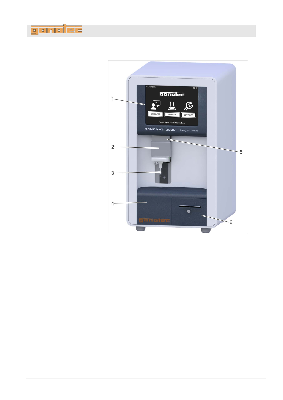
Fig.
1
Touchscreen, page 30
2 Upper cooling system (behind movable elevator cover),
page 29
3
Temperature sensor with measurement vessel, page 29
4
Lower cooling system, page 29
5 Elevator
6
Printer (Option D), page 32
(does not apply to OSMOMAT 3000basic)
1 Overview
Overview
1: Device overview—front
Version 1.22 1/6/2016 9
Page 10

OSMOMAT 3000
basic
// OSMOMAT 3000
Device,
Fig.
1
Interfaces, page 33
(does not apply to OSMOMAT 3000
2 Microfuses
3 On/Off switch
4 Power cable connection
5 Fan outlet
Overview
rear
2: Device overview—rear
basic)
10 Version 1.22 1/6/2016
Page 11
OSMOMAT 3000
basic
// OSMOMAT 3000
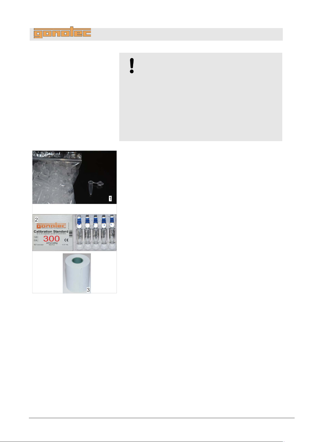
Standard accessories
Fig.
1 Measurement vessels, 100 pc.
2
Calibration standard, 10 pc., 1ml each,
concentration
3 Printer paper, 1 roll (Option D only)
Overview
NOTE!
Risk of falsified measurement results!
When using accessories and/or consumables made
by manufacturers other than Gonotec GmbH, the
reproducibility of the measurement results cannot
be guaranteed.
- Always use the accessories and consumables
supplied by Gonotec GmbH.
- Re-order consumables, in particular measurement
vessels, from Gonotec GmbH (see page 3 for
contact information).
300 mOsmol/kg
3: Overview of consumables
Version 1.22 1/6/2016 11
Page 12
OSMOMAT 3000
basic
// OSMOMAT 3000
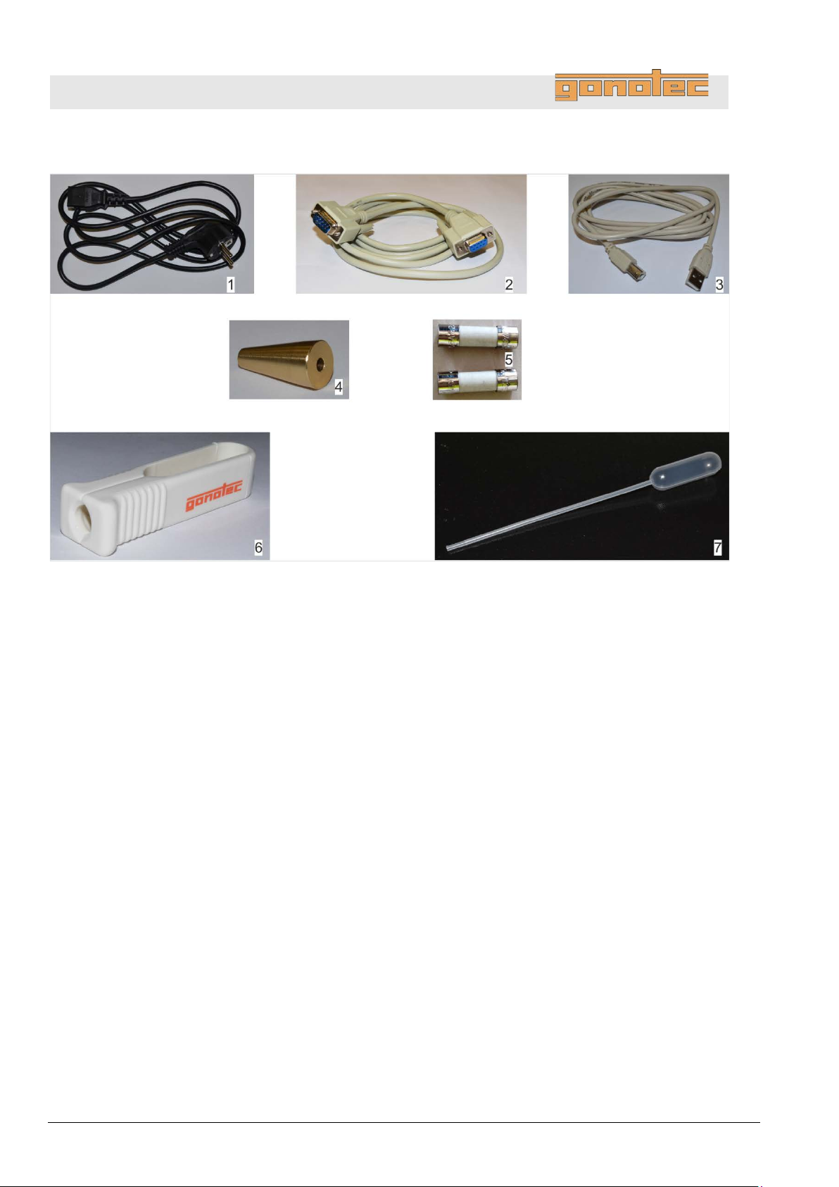
Accessories
Fig.
1 Power cable
2
RS-232 cable
(does not apply to OSMOMAT
3
USB cable for connection to PC (slave)
(does not apply to OSMOMAT 3000
4 Adjustment tool
5 2 microfuses, slow-blow 1.6A (HBC 1500A)
6 Ampoule opener
7 Blow-out device for removing condensate
Overview
4: Overview of accessories
3000basic)
basic)
12 Version 1.22 1/6/2016
Page 13
OSMOMAT 3000
basic
// OSMOMAT 3000
Safety notices
The safety notices in this manual are identified by symbols. The safety
notices are preceded by signal words indicating the degree of hazard.
2 Safety
2.1 Explanation of symbols
Safety
DANGER!
This combination of symbol and signal word indicates an
immediate dangerous situation that will result in death or
serious injury if not avoided.
WARNING!
This combination of symbol and signal word indicates a
potentially dangerous situa t ion that may result in death
or serious injury if not avoided.
CAUTION!
This combination of symbol and signal word indicates a
potentially dangerous situation that may result in minor
or light injury if not avoided.
NOTE!
This combination of symbol and signal word indicates
a potentially dangerous situation that may result in
property damage if not avoided.
NOTE!
This combination of symbol and signal word indicates
potential environmental hazards.
Version 1.22 1/6/2016 13
Page 14
OSMOMAT 3000
basic
// OSMOMAT 3000
Special safety notices
Safety notices use
Safety notices in instructions
Safety notices can apply to specific, individual instructions. These
safety notices are embedded in the instruction to avoid interrupting
the
signal
Example:
1
Loosen screw.
2
Use care when closing cover.
3
Tighten screw.
Additional identifiers
To highlight
the following identifiers are used in this manual:
Identification
Explanation
Safety
the following symbols to indicate special hazards:
WARNING!
This combination of symbol and signal word indicates a
potentially dangerous situation that may result in
contamination with biohaza rdous m ater ials.
Observe the current Ordinance on Biological Substances
and refer to the lab protocol.
DANGER!
This combination of symbol and signal word indicates an
immediate dangerous situation due to electrical current.
Failure to observe a warning identified this way may
result in serious or deadly injury.
flow of reading while perf orm ing the operat ion. They use the
words described above.
.
.
CAUTION!
Pinch hazard on cover!
.
instructions, results, lists, references, and other elements,
1, 2, 3 ...
Step-by-step instructions
Results of action steps
References to sections in this manual and
other applicable documents
Unordered lists
14 Version 1.22 1/6/2016
[Button] Controls (such as buttons or switches),
display elements (such as indicator lamps)
Display Screen elements (such as buttons, function
key assignments)
Page 15
OSMOMAT 3000
basic
// OSMOMAT 3000
Intended use
Electrical current
2.2 Intended use
The OSMOMAT 3000 device is a non-invas i ve in-vitro diagnostic
product used to determine the osmolality of aqueous solutions.
Only use the device to measure aqueous solutions.
Never measure organic, saturated, or highly viscous solutions.
Never administer measured samples to humans by infusion
or injection.
Never use calibration standards as cleaning solutions,
e.g. for contact lenses.
Only use accessories and consumables supplied by
Gonotec GmbH for measurements.
Accessories and consumables on page 25.
2.3 Additional hazards
2.3.1 Hazards due to electrical current
Safety
DANGER!
Risk of death due to electrical current on device!
Class I devices must be connected to a power socket
with protective ground wire.
If the power or device connector is used as a separation
device, the connector must be easily accessible at all
times.
Remove the power plug from the power socket to safely
disconnect the device from mains voltage.
Contact with energized parts of the device results in
immediate risk of death due to electric shock. Damage to
the insulation of individual components can cause risk of
death.
- Only have qua lifie d per sonnel perform repair and
maintenance work on the device.
- If the insulation is damaged, immediately disconnect
the power plug and schedule a repair.
- Always route the power cable so it is not subject to
stress and cannot be bent, pinched, or rolled over
and is not exposed to liquids or heat.
- Keep energized parts away from liquids. Otherwise,
shorts may occur.
Version 1.22 1/6/2016 15
Page 16
OSMOMAT 3000
basic
// OSMOMAT 3000
Risk of infection
Risk of injury
Safety
2.3.2 Risk of infection
WARNING!
Risk of infection due to sample residue and in case
of inadequate hygiene, disinfection, and sterilization
procedures!
Exposure to sample residue in non-cleaned, nonsterilized, or non-disinfected components results in
an elevated risk of infection.
- Wear lab gloves during any kind of work.
- Observe all local regulations regarding hygiene,
disinfection, and sterilization.
We recommend using detergents such as Mikrozid®
AF Liquid, Bac il lo l® plus 3%, or Korsolex® plus 4%
commonly found in clinical-chemical labs to clean
and decontaminate the device.
2.3.3 Risk of injury
CAUTION!
Risk of injury from cryst-needle!
When installing and removing the cryst-needle and
the temperature sensor, the tip of the cryst-needle is
exposed. Movement of the cryst-needle can cause
needle puncture injuries.
- Always keep your hands and fingers clear from
the area underneath the cryst-needle.
16 Version 1.22 1/6/2016
Page 17
OSMOMAT 3000
basic
// OSMOMAT 3000
Exposure to
Fan
Shock
ESD
2.3.4 Risks of device damage
liquids and moisture
Safety
NOTE!
Device damage due to exposure to liquids and
moisture!
Exposure to liquids and moisture can cause damage
to the electrical components of the device, e.g. due to
a short.
- Install the device on a dry workplace.
- Always use a moistened wipe to disinfect the device,
but never a wet wipe.
- Never use the device outdoors.
NOTE!
Device damage due to insufficient air circulation!
Obstruction of the fan outlet at the rear of the device
can cause damage to the device.
- Always keep the fan outlet clear.
NOTE!
Risk of property damage due to exposure of the
device to strong shock!
The device includes precision-engineered components
which can be decalibrated and/or damaged in case of
exposure of the device to strong shock.
- Alwa ys insta ll the device on a non-vibrating surface.
NOTE!
Risk of property damage due to electrostatic
discharge!
Electrostatic discharge (ESD) can occur when working
on the open device.
- Take ESD precautions.
Version 1.22 1/6/2016 17
Page 18
OSMOMAT 3000
basic
// OSMOMAT 3000
Incorrect measurement
Improper handling of
the
Shock
Safety
2.3.5 Reproducibility of the measurement
vessels
calibration standard
NOTE!
Impaired reproducibility of measurement due to
incorrect measurement vessels!
Repeated use of the measurement vessels and use of
incorrect consumables cannot guarantee reproducible
measurement results.
- Always use a clean and unused measurement
- Only use measurement vessels supplied by
- Never use centrifuge tubes or reaction vessels.
NOTE!
Impaired reproducibility of measurement due to
improper handling of calibration standards!
Improper handling and storage of the calibration
standards included with the delivery negatively affects
the measurement accuracy of the device.
- Always observe the stability of the calibration
- Never use opened ampoules twice or mix them
- Never fr ee ze opened ampoules.
- Do not use the calibration standards past their
vessel for every measurement.
Gonotec GmbH.
standards after opening the ampoule (max. 0.5h
at 22°C ambient temperature).
together.
expiration date.
18 Version 1.22 1/6/2016
NOTE!
Increased risk of incorrect measurements!
The device includes precision-engineered components
which can be decalibrated and/or damaged in case of
exposure of the device to strong shock. This can cause
a higher risk of incorrect measurements (spontaneous
crystallization).
- Alwa ys insta ll the device on a non-vibrating surface.
Page 19

OSMOMAT 3000
basic
// OSMOMAT 3000
The operator of the device must fulfill the responsibilities according to
Germany’s Medical Devices Operator Ordinance listed in this manual.
The device is used for medical
Therefore, the operator is subject to the legal responsibilities
regarding work safety.
In particular, the following applies:
2.4 Operator responsibilities
The operator has to learn about the applicable work safety
regulations and determine additional risks resulting from the
specific working conditions at the location the device is used by
means of a risk assessment. These must be implemented by
means of operating instructions for the device.
The operator has to learn about the applicable hygiene regulations
resulting from the samples at the location the device is used.
These must be implemented by means of operating instructions
for the device.
During the entire operating time of the device, the operator has to
verify that the operating instruc tions creat ed b y him /he r meet the
current body of regulations and update them if necessary.
The operator has to determine and lay down the specific
responsibilities for installation, operation, troubleshooting,
servicing, disinfection, and c leaning .
The operator has to make sure that all personn el wor king with
the device have read and understood this manual. In addition,
s/he has to provide regular training for personnel and educate
them about risks.
The operator has to equip personnel with the required safety gear
and issue mandatory instructions for wearing the required safety
gear.
The operator has to make sure that the service intervals specified
in this manual are observed.
The operator has to make sure that consumables are available in
sufficient quantities.
Safety
In addition, the operator is responsible for learning about
and complying with all local laws and associated
standards and guidelines applicable at the time
the device is used.
-pharmaceutical applications.
Version 1.22 1/6/2016 19
Page 20

OSMOMAT 3000
basic
// OSMOMAT 3000
Inventory
The operator has to maintain an inventory according to Germany’s
Medical Devices Operator Or dinance:
Safety
The following information has to be maintained in the inventory:
name, product type, serial number, and year the device was
purchased,
address of Gonotec GmbH
organization-specific ID, if applicable
location of operator
schedule of safety inspections
Store CE-certificate together with inventory.
Store inventory so it is accessible to personnel in charge of
operating the device at all times.
Make documentation available to the responsible authorities
upon demand.
20 Version 1.22 1/6/2016
Page 21
OSMOMAT 3000
basic
// OSMOMAT 3000
This manual specifies
the
User
Based on his or her expert medical and/or pharmaceutical training,
knowledge, and experience, the user is capable of safely executing
the tasks assigned to him or her.
The user is
The user is capable of independently detecting, evaluating, and
avoiding possible risks.
The user has the expert knowledge for the intended use of the device
and observes all hygiene regulations for rooms
purposes and the use of medical products.
The user knows the contents of all applicable regulations, guidelines,
and standards required by law for the safe use of the device and is
capable of meeting the requirements stipulated therein.
Lab supervisor
The lab supervisor coordinates and monitors the technical procedures
at the installation site of the device.
Based on his or her professional training and many years of
professional experience with medical devices, the lab supervisor is
ca
the manufacturer.
Service technician
Based on his or her professional training in the area of mechanical
and electrical engineering, the service technician is capable of
performing the
delegated to him or her by the manufacturer.
2.5 Personnel requirements
WARNING!
Risk of injury due to inadequately qualified
personnel!
Work performed on the device by unqualified personnel
or the presence of unqualified personnel in the hazard
zone of the device creates risks that can result in serious
injury and substantial property damage.
- Only have qualified personnel perform any kind
of activity.
the following personnel qualifications for
different task areas:
Safety
not authorized to perform any start-up activities.
pable of performing the start-up tasks delegated to him or her by
tasks related to troubleshooting and servicing
used for medical
Version 1.22 1/6/2016 21
Page 22

OSMOMAT 3000
basic
// OSMOMAT 3000
While performing the different tasks on and with the device, personnel
must wear the personal safety gear referenced explicitly in the various
sections of this manual.
Description of personal safety gear
The personal safety gear is explained below:
Disposable lab gloves
Disposable lab gloves protect the hands from touching sample
residue.
The following environmentally hazardous substances are used:
Electronic components
Electrical components can contain poisonous substances. These must
not be released into the environment. Therefore, a specialist disposal
firm must be tasked with disposal.
Sodium chloride
The
is
environment.
Safety
2.6 Personal safety gear
2.7 Environmental protection
NOTE!
Danger to environment due to incorrect handling of
handling of environmentally hazardous substances!
Incorrect handling of environmentally hazardous substances,
in particular incorrect disposal, can result in significant harm
to the environment.
- Always observe the warnings regarding the handling of
environmentally hazardous substances and their disposal
below.
- If environmentally hazardous substances are inadvertently
released into the environment, immediately initiate suitable
actions. If in doubt, notify the responsible local authority
about the damage and inquire about suitable actions to
be initiated.
calibration standards contain sodium chloride. Sodium chloride
mildly hazardous to water and must not be released into the
22 Version 1.22 1/6/2016
Page 23
OSMOMAT 3000
basic
// OSMOMAT 3000
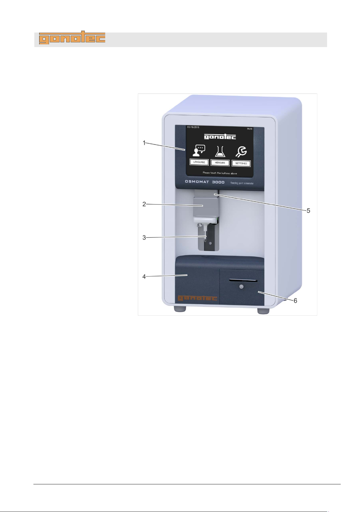
Fig.
1
Touchscreen, page 30
2
Upper cooling system (behind movable elevator cover),
page 29
3
Temperature sensor with measurement vessel, page 29
4
Lower cooling system, page 29
5
Elevator
6
Printer (Option D), page 32
(does not apply to OSMOMAT 3000basic)
Design and function
3 Design and function
3.1 Device overview
5: Device overview—front
Version 1.22 1/6/2016 23
Page 24
OSMOMAT 3000
basic
// OSMOMAT 3000
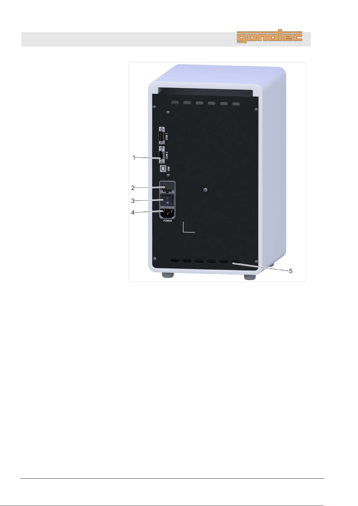
Device, rear
Fig.
1
Interfaces, page 33.
(does not apply to OSMOMAT 3000
2 Microfuses
3 On/Off switch
4 Power cable connection
5 Fan outlet
Design and function
6: Device overview—rear
basic)
24 Version 1.22 1/6/2016
Page 25
OSMOMAT 3000
basic
// OSMOMAT 3000
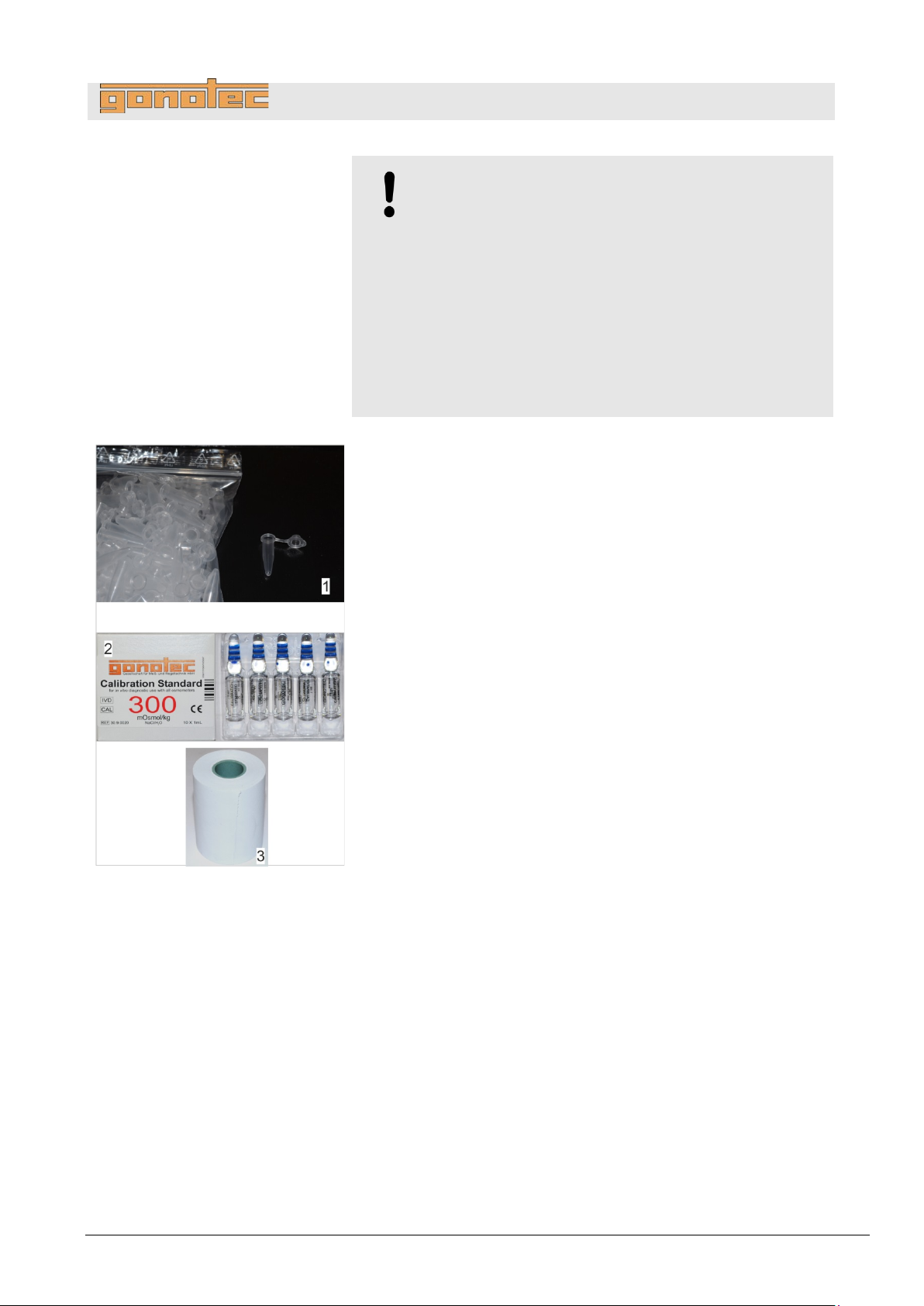
Standard accessories
Fig.
1 Measurement vessels, 100 pc.
2
Calibration standard, 10 pc., 1ml each,
concentration
3 Printer paper, 1 roll (Option D only)
Design and function
NOTE!
Risk of falsified measurement results!
When using accessories and/or consumables made
by manufacturers other than Gonotec GmbH, the
reproducibility of the measurement results cannot
be guaranteed.
- Always use the accessories and consumables
supplied by Gonotec GmbH.
- Re-order consumables, in particular measurement
vessels, from Gonotec GmbH (see page 3 for
contact information).
300 mOsmol/kg
7: Overview of consumables
Version 1.22 1/6/2016 25
Page 26
OSMOMAT 3000
basic
// OSMOMAT 3000
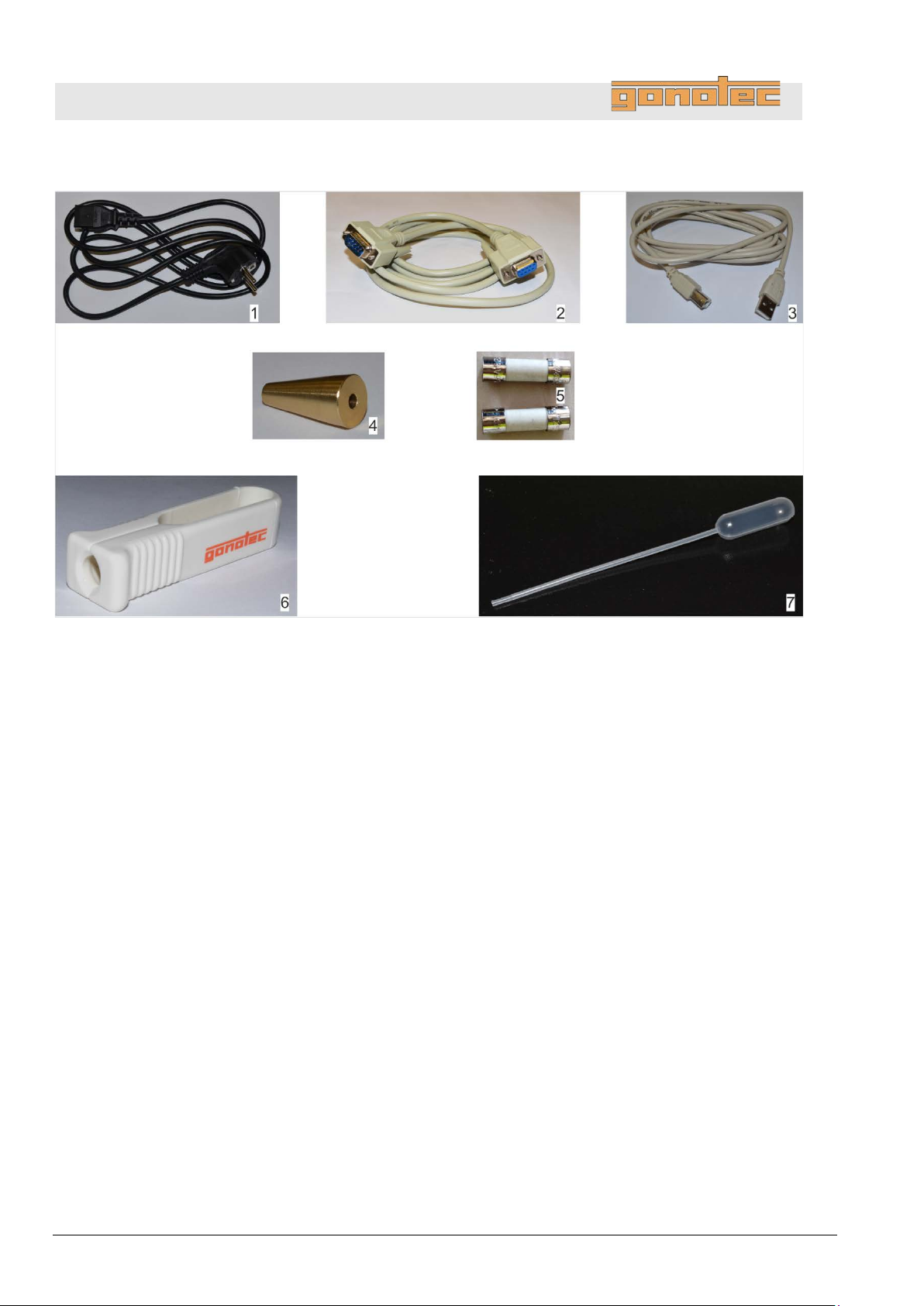
Accessories
Fig.
1 Power cable
2
RS-232 cable
(does not apply
3
USB cable for connection to PC (slave)
(does not apply to OSMOMAT 3000
4 Adjustment tool
5 2 microfuses, slow-blow 1.6A (HBC 1500A)
6 Ampoule opener
7 Blow-out device for removing condensate
Design and function
8: Overview of accessories
to OSMOMAT 3000basic)
basic)
26 Version 1.22 1/6/2016
Page 27
OSMOMAT 3000
basic
// OSMOMAT 3000
Osmolality
The device measures the total osmolality of any aqueous solution.
The osmolality of a solution is defined as the number (or amount of
substance) of the osmotically active particles (e.g.
urea, proteins) present per kilogram of solvent (water).
The osmolality is specified in Osmol/kg or mOsmol/kg.
The device determines the total osm olalit y of a sam ple solution
based
The
where the device is first calibrated based on the freezing points of
distilled water and one or two calibration solutions with known
osmolality. Next, the osmolality of unknown sample solutions is
determined with reference to this 2/3
Freezing point depression
The freezing point of a solvent is depressed by adding soluble or
mixable substances. The magnitude of this effect depends less on
the
number of particles present in the solution afterwards.
Whereas water has a freezing point of 0°C, an aqueous solution
with
a
That means that one mol of an ideal non
(6.023
freezing point of a solution by
The osmolality of a solution is directly proportional to the mea
freezing point depression and can therefore be calculated from this
result. The relationship is as follows:
3.2 Measuring method basics
Design and function
salt ions, sugar,
on the freezing point depression (see below).
implemented measuring method is a relative measuring method
-point calibration.
type and quantity of the dissolved substance, but rather on the
an osmotically active particle concentration of 1 Osmol/kg has
freezing point of -1.858°C.
× 1023 parts diluted in one kilogram of water) lowers the
C
= osmolality [Osmol/kg]
C
osm
= ΔT / K
osm
ΔT = freezing point depression [°C]
K = 1.858°C kg/Osmol (cryoscopic constant)
-dissociated substance
1.858°C.
sured
Version 1.22 1/6/2016 27
Page 28
OSMOMAT 3000
basic
// OSMOMAT 3000
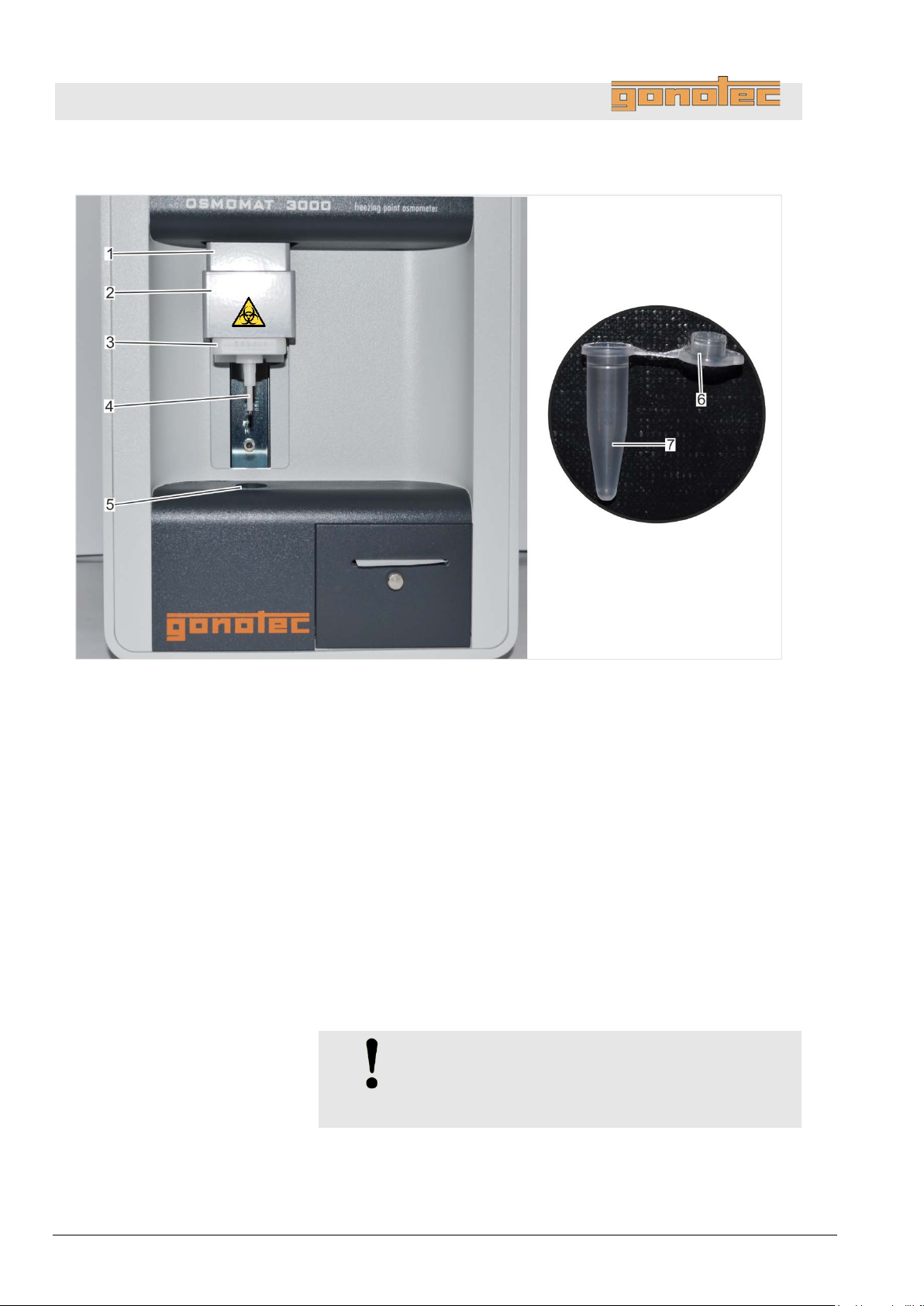
Fig.
1 Elevator
2
Upper cooling system
(behind movable elevator cover)
3 Handle for lowering the temperature sensor
4 Temperature sensor
5 Lower cooling system
6 Cover
7 Measurement vessel
The sample is pipetted into the measurement vessel (
The
(
The
temperature.
The defined crystallization of the sample is triggered using ice
crystals
The osmolality of the sample is calculated using the measured
freezing point [°C] and the cryoscopic constant and shown on
the
Design and function
3.3 Measurement equipment
9: Overview of measurement equipment
measurement vessel is placed on the temperature sensor
Fig. 9/4) and lowered into the lower cooling system (Fig. 9/5).
lower cooling system cools the sample down to a defined
produced in the upper cooling system (Fig. 9/2).
display.
NOTE!
Risk of incorrect measurement resulti n g from
the presence of air bubbles in the sample!
The sample must be pipetted without air bubbles.
28 Version 1.22 1/6/2016
Fig. 9/7).
Page 29

OSMOMAT 3000
basic
// OSMOMAT 3000
Upper cooling system
Fig.
1 Cryst-needle
2 Cooling nipple
The cryst
the sample with ice crystals ("crystallization"). This causes the sample
to freeze and heat up to its freezing point.
Temperature sensor
Fig.
1 Temperature sensor
2 Thermistor
The temperature sensor (
of the sample via the thermistor (
been triggered, the temperature sensor measures the freezing point
of
Lower cooling system
The lower cooling system quickly cools the sample down to a defined
temperature which is below the freezing point of the solution.
The
in
10: Upper cooling system
Design and function
-needle (Fig. 10/1) of the upper cooling system "inoculates"
WARNING!
Risk of infection from sample residue!
The cryst-needle is immersed into the sample during
measurements. Contact with the cryst-needle increases
the risk of infection.
- Wear lab gloves during any kind of work.
the sample.
NOTE!
Sensitive component!
The thermistor of the temperature sensor is a sensitive
component and must be protected from external
11: Temperature sensor
influences such as dust or friction.
- When performing any kind of work on the device,
place a measurement vessel on the thermistor.
- At the end of the work on the device, place a
measurement vessel on the thermistor for protection.
quick cooling down of the sample causes the sample to remain
the liquid state until the defined crystallization is triggered.
Fig. 11/1) measures the current temperature
Fig. 11/2). After crystallization has
Version 1.22 1/6/2016 29
Page 30
OSMOMAT 3000
basic
// OSMOMAT 3000
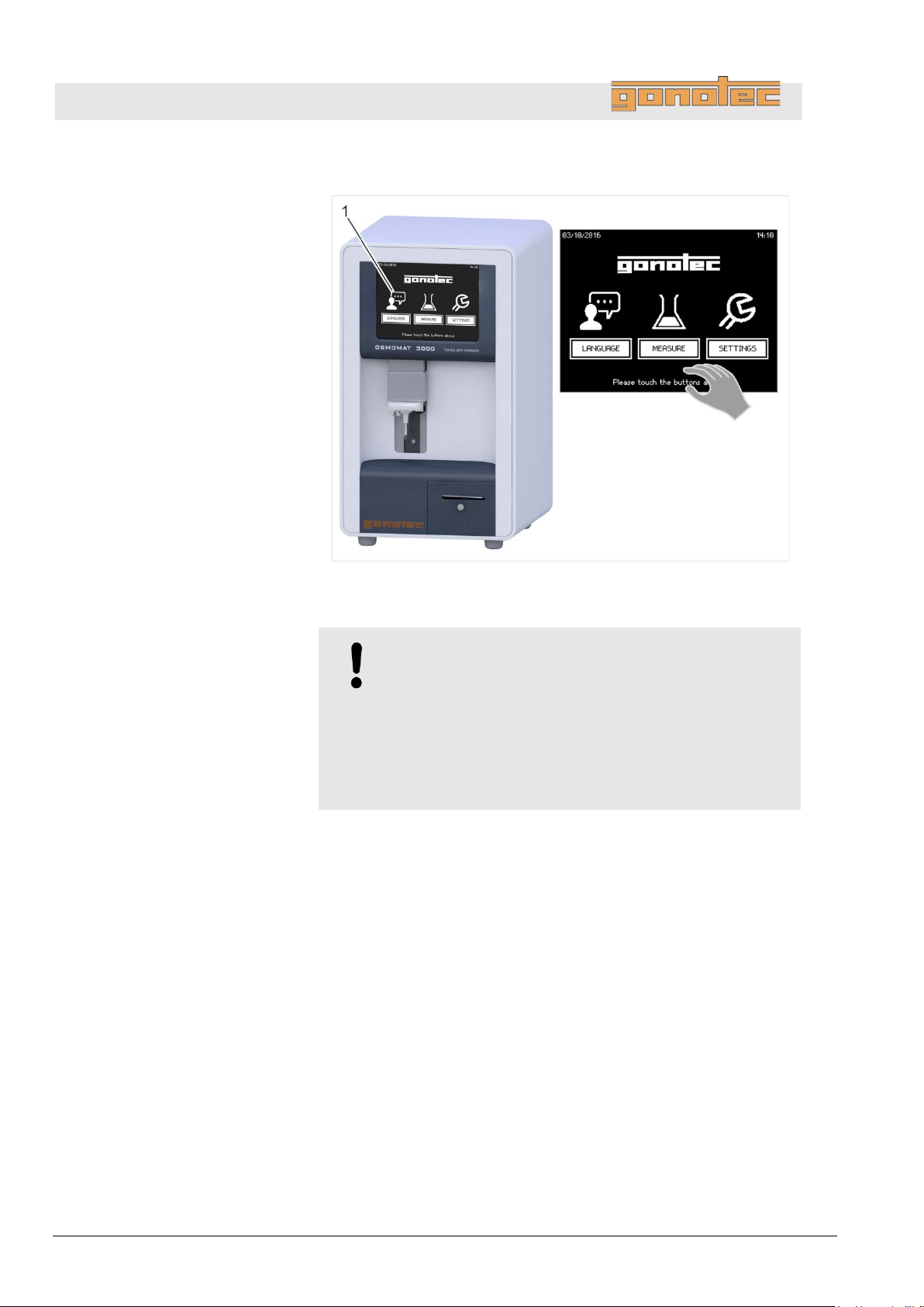
Fig.
The device is controlled using the touchscreen (
Design and function
3.4 Touchscreen
12: Overview of touchscreen
Fig. 12/1)
NOTE!
Property damage due to incorrect operation!
The touchscreen can be damaged by sharp or hard
objects or excessive pressure force.
- Only operate the touchscreen using fingers or
a touchpen.
- Only tap the touchscreen (do not press).
30 Version 1.22 1/6/2016
Page 31
OSMOMAT 3000
basic
// OSMOMAT 3000
Enter values
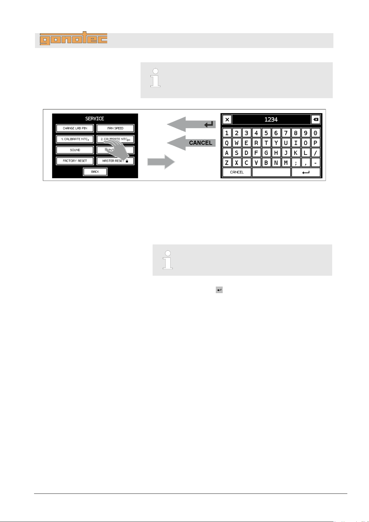
Fig.
1. To enter values, tap the corresponding entry field in the opened
menu.
This opens an on
2
Enter the
3
To save the value, tap
The newly entered value overwrites the previous value.
13: Enter values
Some menus are password-protected.
Access to these menus is limited to the lab supervisor
or authorized service personnel/Gonotec.
Design and function
.
value.
-screen keyboard.
To close the on-screen keyboard without saving
the entered value, tap [Cancel].
.
.
Version 1.22 1/6/2016 31
Page 32
OSMOMAT 3000
basic
// OSMOMAT 3000
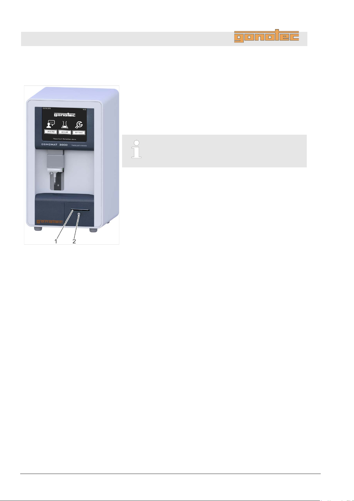
Fig.
With built-in printer only (Option D)
1 Opening for printer paper
2 Printer pull-out handle
The printer is used to print the measurement results. Rolls
paper are included with the delivery.
Change printer paper
Design and function
3.5 Printer (does not apply to OSMOMAT 3000basic)
Change the printer paper when a red stripe appears on
the printer paper ( chapter 8.4.5 on page 90).
of printer
14: Overview of printer
32 Version 1.22 1/6/2016
Page 33
OSMOMAT 3000
basic
// OSMOMAT 3000
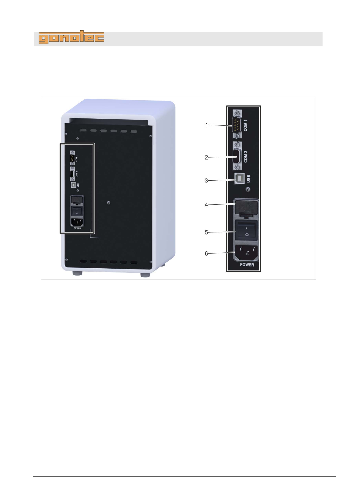
The following connections and interfaces are located at the rear of
the
Fig.
1
COM1 (only for connecting barcode reader)
(does not apply to OSMOMAT 3000
2
COM2 interface (RS-2 32 o utput)
(does not apply to OSMOMAT 3000
3
USB port
(does not apply to OSMOMAT 3000
4 Fuse insert
5 On/Off switch
6 Power plug connection
Design and function
3.6 Connections and interfaces (does not apply to OSMOMAT 3000basic)
device:
15: Connections and interfaces
basic)
basic)
basic)
Version 1.22 1/6/2016 33
Page 34
OSMOMAT 3000
basic
// OSMOMAT 3000
COM1 data port
(does not
OSMOMAT
The upper COM1 (RS232) serial data port is used to connect a barcode
reader. The barcode reader is configured at the factory and can be
purchased from Gonotec GmbH or your authorized distributor.
WARNING!
Incompatible barcode
The use of a barcode reader other than the barcode
reader supplied by Gonotec GmbH is not recommended
because potential incompatibilities cannot be ruled out.
COM2 or USB data port
(does not apply to
OSMOMAT
WARNING!
To protect life and equipment:
Devices and accessories connected to the RS232
or
standards for medical lab equipment.
Fig.
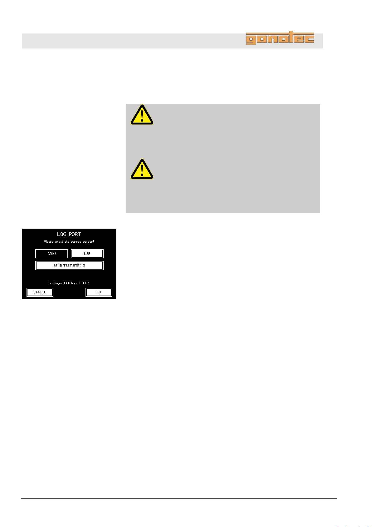
The device can output the
COM2
To select the data port, select Log Port from the Settings menu item.
The following screen lets you select between COM2 and USB.
USB port driver
A software
methods for installing the driver:
Design and function
3.6.1 Interface configuration
apply to
3000basic)
3000basic)
reader!
USB connectors must meet the applicable safety
(RS232) serial data port in the middle or the USB port.
16: Set log port
driver is required to use the USB port. There are two
- Automatic: Connect the device to the PC using the USB cable
and switch on the device. The operating system of the PC
detects the interface, automatically installs the required software
driver and notifies the user that installation was successful. The
USB port can now be used as an additional COM interface.
- Manual: The PC does not automatically detect the device or
the operating system is missing the required software driver.
In this case, please follow the instructions on the included CD.
It includes both the installation instructions for the corresponding
Windows operating system and the software driver itself.
34 Version 1.22 1/6/2016
recorded measurement results via the
Page 35
OSMOMAT 3000
basic
// OSMOMAT 3000
Format
Description
Advantages
Disadvantages
CSV
Line by line comma-
Compact
Checksum acts as backup
Not a genuine standard format
XML
Standardized,
Standardized
Checksum acts as backup
Not very compact
Legacy CSV
CSV format
Compatible with legacy devices and
Syntax not always clear
continuing to use this format!
Parameter
Value
Rate
9600 baud
Data bits
8
Parity
None
Stop bit
1
Coding
ASCII
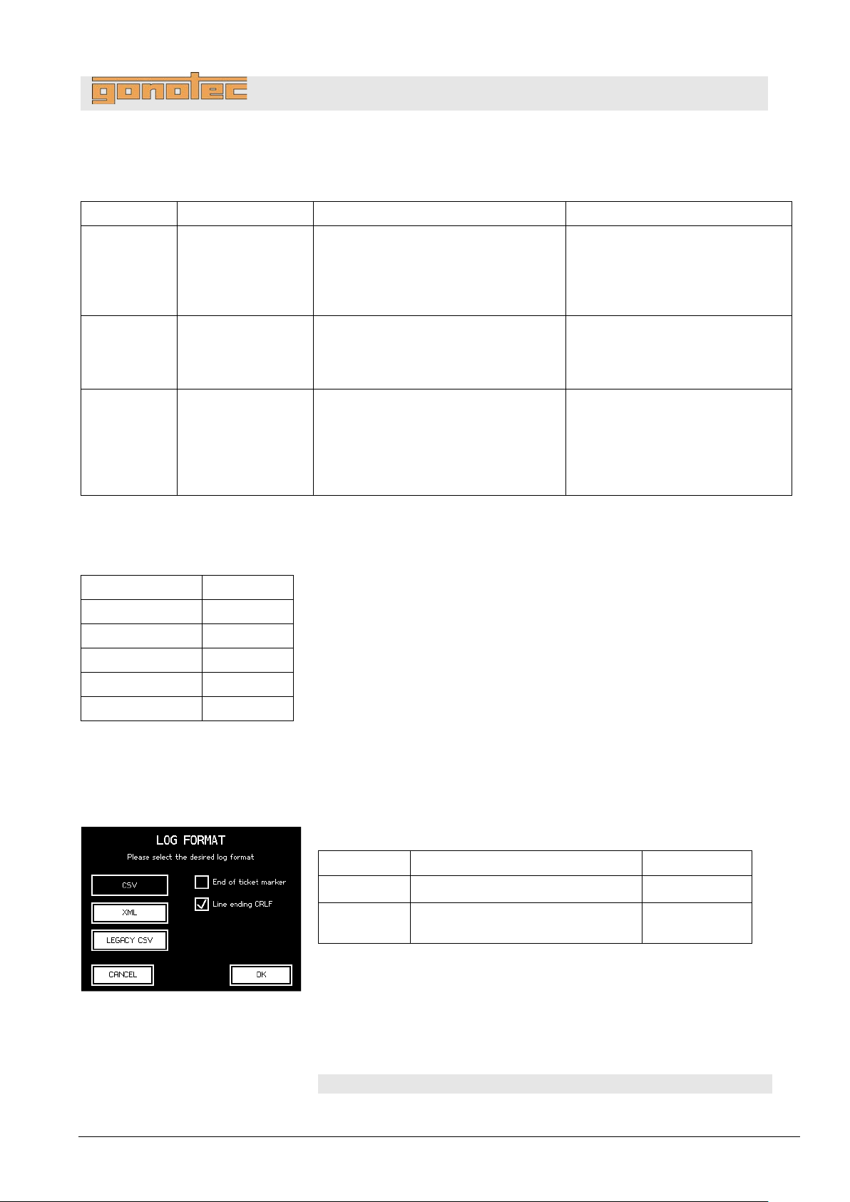
Data is transferred via the serial interface in the laboratory options with
the transfer parameters set as follows.
These settings are also usually referred to as
Fig.
End of line markers:
The end of each displayed line can optionally be marked as follows.
The end of the line is marked as ⏎
End of ticket markers:
An “end of ticket” marker can optionally be selected. This setting means
that a line is displayed as follows after each individual sample
measurement or after the end of the batch:
EndOfTicket⏎
Name
Description
ASCII
CR
Carriage return
0x0D
CRLF
Carriage return and
line feed
0x0D 0x0A
Design and function
3.6.2 Log formats
The log output for the Osmomat 3000 may optionally be in one of the following three formats:
separated values
placed within
quotation marks
expandable markup
language
from previous
generations
of devices
Can be uploaded into spreadsheets
(e.g. OpenOffice or Excel)
Easily human-readable
Compatible with large number of APIs
Human-readable
interfaces
May cause data to be
misinterpreted
For reasons of security we
strongly advise against
A more detailed description of the formats is provided below.
3.6.3 Data transfer
3.6.4 General options
The following options can be set for all formats using the laboratory options.
9600/8N1.
.
17: Log formats
Version 1.22 1/6/2016 35
Page 36
OSMOMAT 3000
basic
// OSMOMAT 3000
Line content
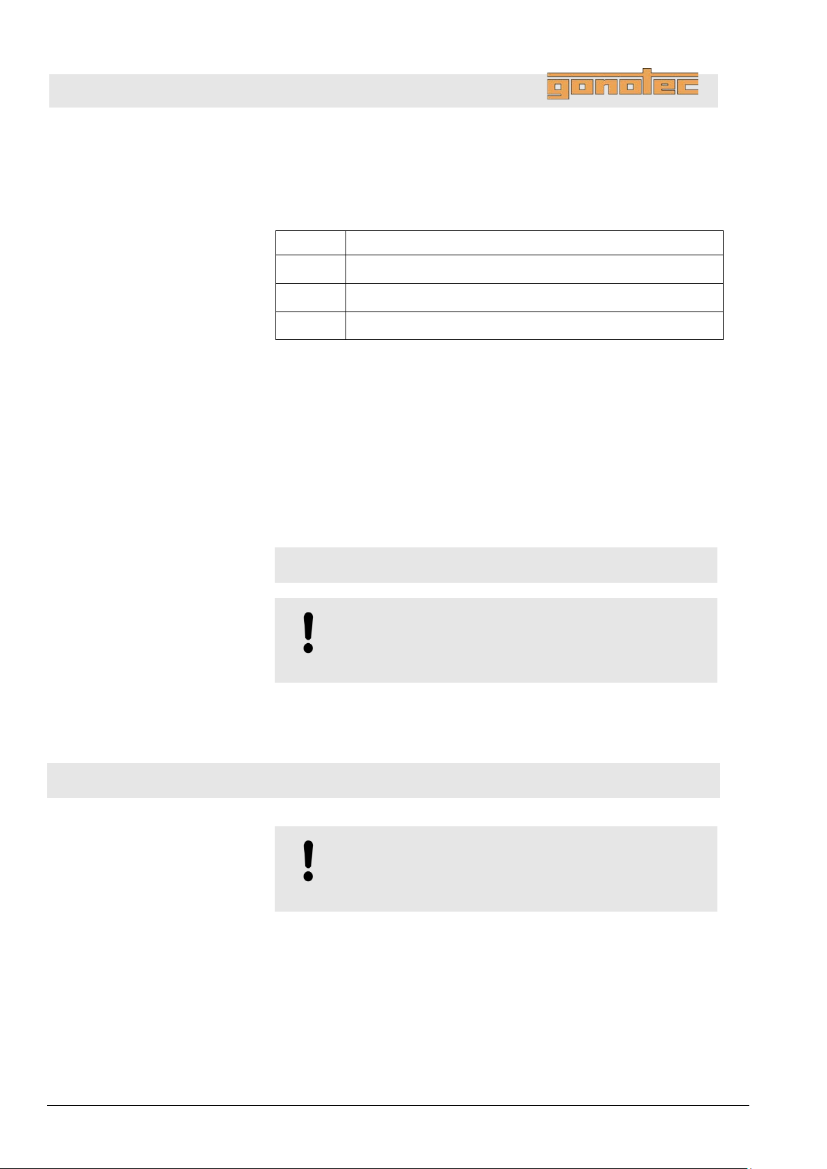
There are three types of line content
Line group
Every line within the CSV format contains several semicolon(ASCII:0x3B)
quotation marks (ASCII:0x22). Whether or not quotation marks are used
depends on the value format. They are not used
times, but they are used for text values.
Intro line
When the Osmomat 3000 is started, the device sends a line with
version information to prevent future compatibility problems. This line
contains the short name of the device type fol
numbers of the mainboard and the components connected to it.
A
⏎
Title line
The intro line is followed by a line with title names for the values of the
next result lines. This line helps to make the text human
generates practical column titles when imported into a spreadsheet:
Design and function
3.6.5 CSV format
If CSV format is selected, the log is displayed line by line. Each line is separated by the selected end of line symbol.
Type Purpose
Intro Message showing version numbers of device software
Title Column title of the next table of result lines
Result Measurement result or error message
separated values. If necessary, they are enclosed in
for measurements or
lowed by the version
typical intro line looks like this:
OSM3000;Main:V1.22;COM:V1.7;D:V1.10;TEC:V1.6
NOTE!
Changing the settings restarts the logbook and also
publishes a new intro line.
-readable and
"batch";"sample";date;value;"dimension";"device-no";"check";"message"⏎
NOTE!
Changing the settings restarts the logbook and also
publishes a new column title.
36 Version 1.22 1/6/2016
Page 37
OSMOMAT 3000
basic
// OSMOMAT 3000
Result line
After each measurement a result line is sent which contains
the
Column
Description
batch
Batch identifier in quotation marks, entered by the user or a sequential
Void for single measurements and if batch ID is disabled in the options.
sample
Sample identifier in quotation marks, entered by the user or a sequential
Void if sample ID is disabled in the options.
date
Date and time in combined ISO 8601 format
(e.g.: 2015-12-31T13:45).
value
Measurement value as integer.
Error identifier (see Error messages section)
dimension
Unit of the measurement value returned in value enclosed in quotation
Void if value contains an error message.
device-no
Serial number of the device in quotation marks.
check
Checksum of previous values in this line (see Checksum section)
message
Human-readable message always in English in quotation marks.
Void if there is no notification.
Type
Description
SAMPLE
Contains exactly one result from a single measurement
BATCH
Contains several results from a batch measurement
following semicolon-separated values in a fixed order:
number generated automatically.
Or:
number generated automatically.
Or:
Or:
marks ("mOsmol/kg") – regardless of the selected result unit and the
language setting of the device!
Or:
Design and function
Or:
3.6.6 XML format
The XML format is sent line by line but a single record will generally extend across several lines. Each record is
transferred as a ticket and multiple measurements for one batch are combined into one ticket. Strictly speaking,
records are allocated to tickets in the same way as they are published: Each printed record corresponds to one
ticket in the XML log.
There are two types of ticket:
Version 1.22 1/6/2016 37
Page 38
OSMOMAT 3000
basic
// OSMOMAT 3000
Attribute
Description
class
Ticket type (SAMPLE or BATCH)
serialno
Serial number of the device
versions
Version information on the device and connected components
(see Intro line in the CSV format chapter)
Value
Description
BatchId
Batch identifier, entered by the user or a sequential number generated
options.
SampleId
Sample identifier, entered by the user or sequential number generated
Not present if sample ID is disabled in the options.
DateTime
Date and time in combined ISO 8601 format
(e.g.: 2015-12-31T13:45).
Value
Measurement value as integer.
Not present if it is a mismeasurement.
Unit
Unit of the measurement value returned in value enclosed in
Not present if it is a mismeasurement.
Failure
Error identifier (see Error messages section)
Not present if measurement was successful.
DeviceNo
Serial number of the device
CheckSum
Checksum of previous values in this line (see Checksum section)
Message
Human-readable message always in English.
Not present if there is no notification.
Design and function
3.6.6.1 Ticket
A ticket consists of an XML tag which corresponds to one published ticket. If it relates to a single measurement,
it contains an additional XML tag called Measurement, which contains the measurement and the associated
metadata. If it relates to a batch measurement, one ticket may contain several measurements.
A ticket has the following attributes in addition to the measurements contained in it:
3.6.6.2 Measurement
A measurement or mismeasurement is described in a ticket in an XML tag called Measurement, wh ich
contains the following values:
automatically.
Or:
Not present for single measurements and if batch ID is disabled in the
automatically.
Or:
Or:
quotation marks ("mOsmol/kg") – regardless of the selected result
unit and the language setting of the device!
Or:
Or:
Or:
38 Version 1.22 1/6/2016
Page 39

OSMOMAT 3000
basic
// OSMOMAT 3000
Design and function
3.6.6.3 Example of a single measurement
In the case of a single measurement the entire ticket is published in one piece when the measurement has been
completed, the value BatchId does not apply.
<Ticket class="SAMPLE" serialno="300161103"
versions="OSM3000;Main:V1.22;COM:V1.7;D:V1.10;TEC:V1.6">⏎
<Measurement>⏎
<SampleId>PROBE01</SampleId>⏎
<DateTime>2016-02-19T08:34:30</DateTime>⏎
<Value>301</Value>⏎
<Unit>mOsmol/kg</Unit>⏎
<DeviceNo>300161103</DeviceNo>⏎
<CheckSum>172ef346c5f36c964ac0710a8421efc1</CheckSum>⏎
</Measurement>⏎
</Ticket>⏎
• Example of a batch measurement
If a new batch is initiated, a section is published which opens the ticket as an XML tag in the log:
<Ticket class="BATCH" serialno="300161103"
versions="OSM3000;Main:V1.22;COM:V1.7;D:V1.10;TEC:V1.6">⏎
If measurements are then implemented within the batch, a Measurement XML tag follows for each measurement
such as the following:
<Measurement>⏎
<BatchId>CHARGE01</BatchId>⏎
<SampleId>PROBE01</SampleId>⏎
<DateTime>2016-02-19T08:38:02</DateTime>⏎
<Value>301</Value>⏎
<Unit>mOsmol/kg</Unit>⏎
<DeviceNo>300161103</DeviceNo>⏎
<CheckSum>339781763744c176c6b43317d880b782</CheckSum>⏎
</Measurement>⏎
Ending the batch also closes the ticket:
</Ticket>⏎
3.6.7 Legacy CSV format
Format initially used by OSMOMAT 3000 for data transfer.
Select only if required for compatibility with existing LIMS connections configured accordingly. Documentation in
the obsolete CSV format can be requested separately.
We strongly advise against continuing to use this format!
Version 1.22 1/6/2016 39
Page 40

OSMOMAT 3000
basic
// OSMOMAT 3000
ABORT
User cancels by pressing the EXIT key
LIFT
User cancels by lifting the sensor
CANTCOOL
Failed to sufficiently cool down sample
NOCRYST
Crystallization failed
SPONCRYST
Spontaneous crystallization of sample
Design and function
3.6.8 Error messages
The following error messages may be used to diagnose an operating error or device failure:
Notification Meaning
3.6.9 Checksums
The checksum for each result line is calculated from the contents of the values from the columns Batch ID,
Sample ID, Date/time, Measurement, Unit and Device number. A possible result line:
<Measurement>
<SampleId>PROBE01</SampleId>
<DateTime>2016-02-19T08:34:30</DateTime>
<Value>301</Value>
<Unit>mOsmol/kg</Unit>
<DeviceCode>300161103</DeviceCode>
<CheckSum>172ef346c5f36c964ac0710a8421efc1</CheckSum>
</Measurement>
...or…
;"PROBE01";2016-02-19T08:34:30;301;"mOsmol/kg";"300161103";
"172ef346c5f36c964ac0710a8421efc1";
...and the above contents are strung together to form:
PROBE012016-02-19T08:34:30301mOsmol/kg300161103
The MD5 checksum for this string is:
17 2e f3 46 c5 f3 6c 96 4a c0 71 0a 84 21 ef c1
See http://en.toolpage.org/tool/md5 to learn more about MD5 calculation
40 Version 1.22 1/6/2016
Page 41
OSMOMAT 3000
basic
// OSMOMAT 3000
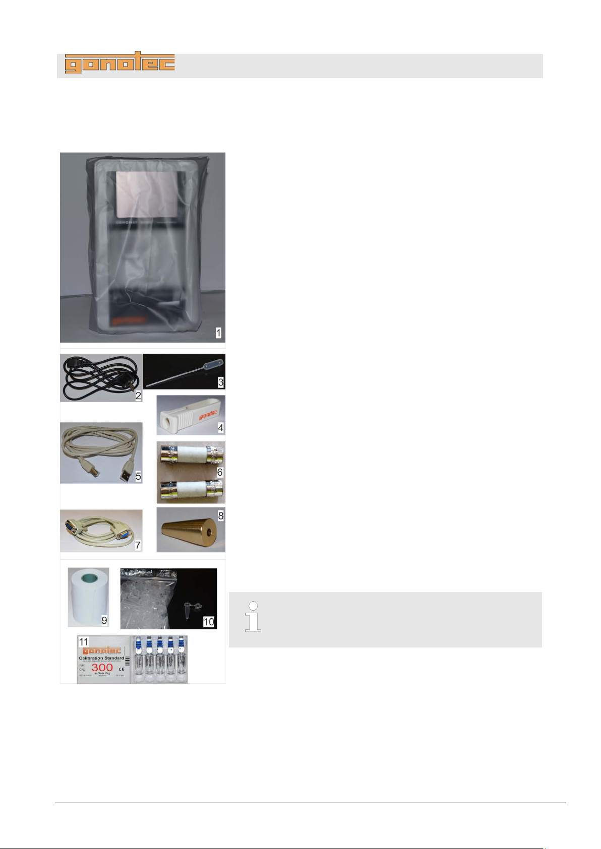
Delivery condition
Fig.
1 package containing the following components:
Check the delivery for completeness and transport damage
immediately following receipt.
Proceed as follows in case of externally visible tr
4 Delivery, packaging, and storage
Delivery, packaging, and storage
Device with protective sleeve (Fig. 18/1)
Accessories (Fig. 18/2–8):
Blow-out device (Fig. 18/3)
Adjustment tool (Fig. 18/8)
1 package of 2 microfuses: slow-blow 1.6A (Fig. 18/6)
Ampoule opener (Fig. 18/4)
USB cable (Fig. 18/5) (does not apply to OSMOMAT 3000basic)
RS-232 cable (Fig. 18/7) (does not apply to OSMOMAT
3000basic)
Power cable (Fig. 18/2)
Standard accessories (Fig. 18/9-11)
Printer paper (Fig. 18/9) (Option D only)
(does not apply to OSMOMAT 3000basic)
Measurement vessels, 100 pc. (Fig. 18/10)
Calibration standard 300mOsmol/kg, 1 package of
10 ampoules/1ml each (Fig. 18/11)
1 user manual
Reject delivery or accept delivery only conditionally.
Note the extent of damage on the transport documents or
the delivery note of the carrier.
Notify Gonotec GmbH and initiate a complaint.
18: Delivery condition
ansport damage:
File a complaint about every defect as so on as it is
detected. Claims for damages can only be filed within
applicable complaint deadlines.
Version 1.22 1/6/2016 41
Page 42
OSMOMAT 3000
basic
// OSMOMAT 3000
About the packaging
The package is packaged according to the expected transport
conditions. Only environmentally friendly
the
The packaging is intended to protect the device from transport
damage and other damage until the time of installation. Therefore,
do
installation.
H
The packaging is multi
of transportation. Keep the packaging for possible return of the device
for repairs. This will save you the ti
equally suitable packaging.
If disposing of the packaging material, observe the following:
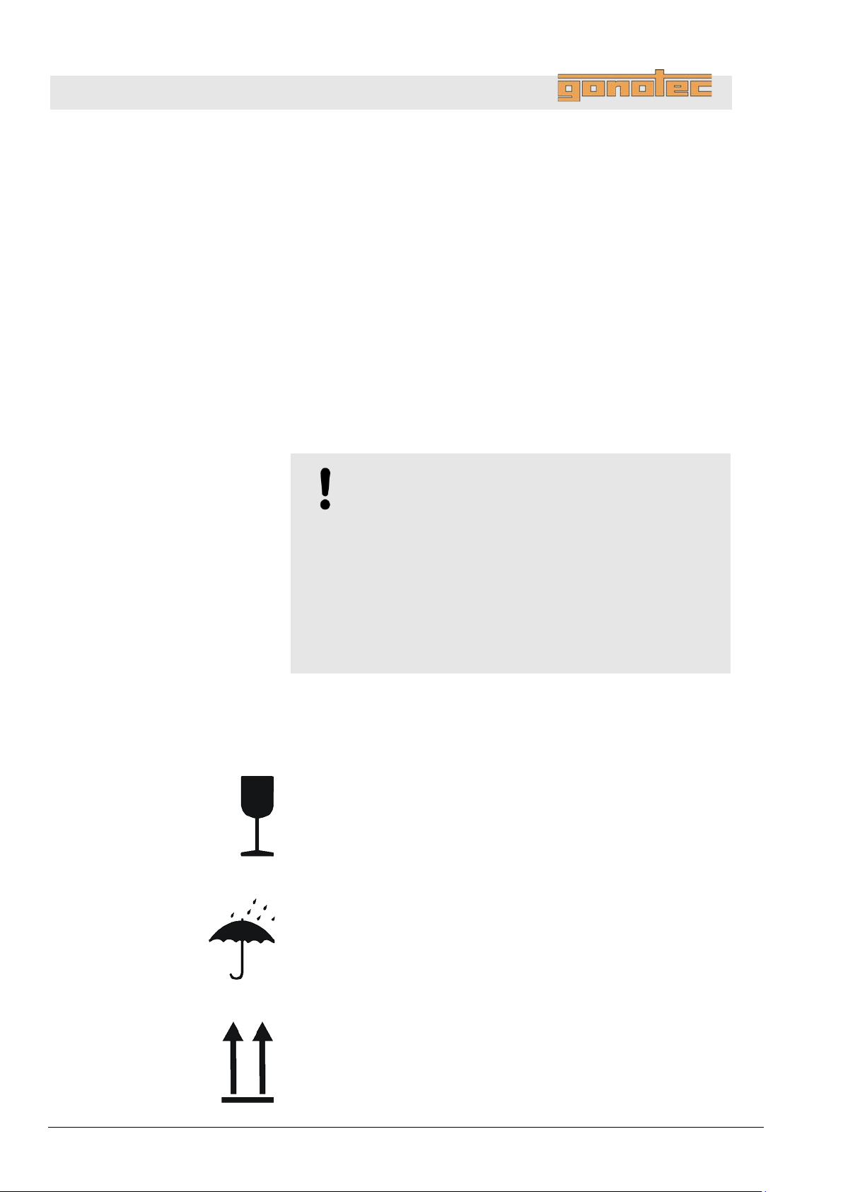
Symbols on packaging
The symbols on the packaging of the device and calibration standard
are explained below:
Fragile
Indicates packages with fragile or sensitive contents.
Handle the package with
to
Protect from liquid
Protect packages from liquid and keep dry.
Package orientation
The arrow tips of the symbol point to the top of the package. They
must point up at all times to prevent damage
Delivery, packaging, and storage
4.1 Packaging
packaging.
not destroy the packaging and do not remove it until just before
andling of packaging materials
materials were used for
-use and ensures a hygienic and safe met hod
me and money needed to find
NOTE!
Danger to environment due to improper disposal!
Packaging materials are valuable resources and can be
re-used or recycled in many cases. Improper disposal of
packaging materials can cause dangers to the
environment.
- Be aware of the environment when disposing of the
packaging material.
- Observe applicable local disposal regulations. If
necessary, task a specialist firm with disposal.
shock.
42 Version 1.22 1/6/2016
care, do not drop, and do not expose
to the contents.
Page 43
OSMOMAT 3000
basic
// OSMOMAT 3000
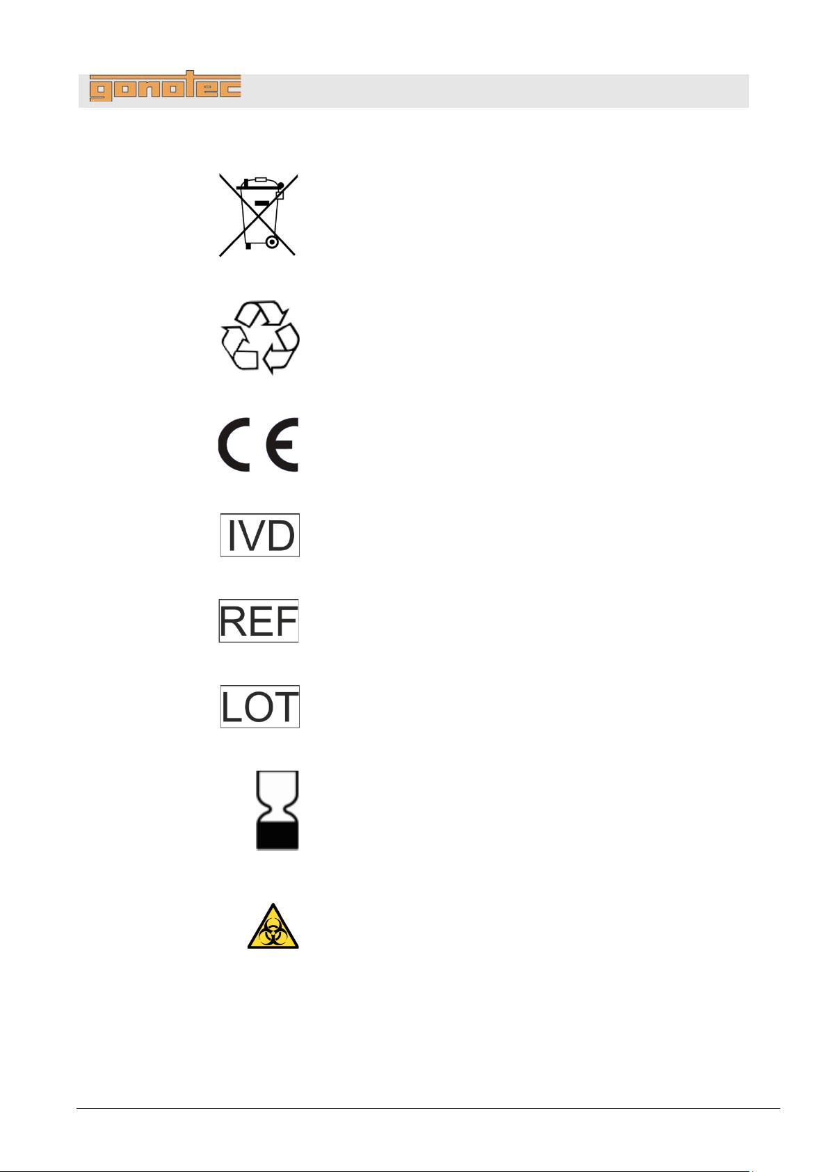
No disposal via municipal waste
Indicates that disposal of the device via municipal waste is prohibited.
Disposal of the decommissioned device should be via electronics and
metal recycling. In addition, decommissioned devices can be
to the manufacturer for disposal.
Package recycling
Indicates that the packaging can be recycled.
Compliance
This product meets the requirements of EEC Directive
to in
In-vitro diagnostic device
Indicates that the product is an in
Item number
Item number
Batch ID
Batch ID of the calibration standard
Biological safety
Biological safety (month, year). Date until which the calibration
standard
Biohazard
Biocontamination warn ing:
Use care when operating upper cooling system and cryst
Delivery, packaging, and storage
returned
98/79 relating
-vitro diagnostic devices.
-vitro diagnostic device.
fulfills its original function if stored properly.
-needle
Version 1.22 1/6/2016 43
Page 44

OSMOMAT 3000
basic
// OSMOMAT 3000
Store the device under the following conditions:
1
Carefully open cardboard box using a knife.
2
Remove device from packaging and place in a suitable location.
3
Keep packaging for possible later return.
Delivery, packaging, and storage
4.2 Device storage
Do not store outside.
Store under dry and dust-free conditions.
Do not expose to aggressive media.
Protect from sunlight.
Protect the temperature sensor using a measurement vessel.
Avoid mechanical shock.
Storage temperature: -10°C to 60°C.
Relative humidity (non-condensing): 5-90%.
If stored for more than 3 months, regularly inspect all parts and
packaging for general integrity.
4.3 Unpack device
.
.
.
44 Version 1.22 1/6/2016
Page 45
OSMOMAT 3000
basic
// OSMOMAT 3000
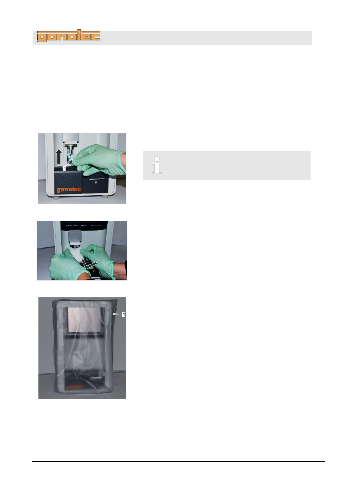
Personnel:
Safety gear:
1. Power down device using on/off switch on rear side and
disconnect power plug.
Fig.
2. Position a measurement vessel (
sensor.
Fig.
3. Tilt transport safety device for temperature sensor and carefully
slide behind the temperature sensor (
Fig.
4. Pull protective sleeve (
device.
5
Lift up device (6.5kg) and carry to installation site.
5 Installation
5.1 Transport device inside lab
19: Position measurement vessel
Installation
User
Disposable lab gloves
Fig. 19/1) on the temperature
The measurement vessel is securely attached to
the temperature sensor when it clicks into place.
20: Position transport safety device
.
21: Device with protective sleeve
Fig. 20).
Fig. 21/1) included with the del i ver y over
Version 1.22 1/6/2016 45
Page 46
OSMOMAT 3000
basic
// OSMOMAT 3000
Personnel:
Safety gear:
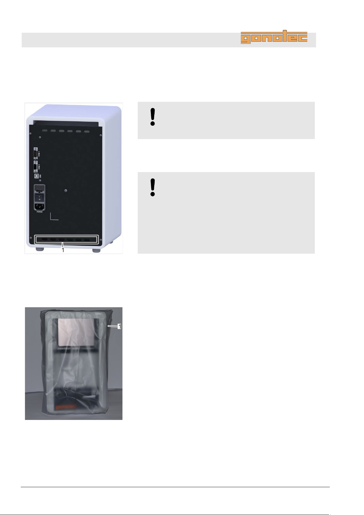
Fig.
1
Install device at installation site.
Keep fan outlet (
Keep fan outlet openings underneath device clear.
Fig.
2
Remove protective sleeve from
Installation
5.2 Install device
22: Fan outlet (1)
User
Disposable lab gloves
.
NOTE!
Risk of property damage!
Only install device indoors.
NOTE!
Risk of incorrect measurements
Select site based on the following criteria:
- free of vibrations
- no direct heat exposure (sun, electric heater, etc.)
- no strong air flows
- free of dust and dirt
Fig. 22/1) on device clear.
.
23: Remove protective sleeve
46 Version 1.22 1/6/2016
device (Fig. 23/1).
Page 47
OSMOMAT 3000
basic
// OSMOMAT 3000
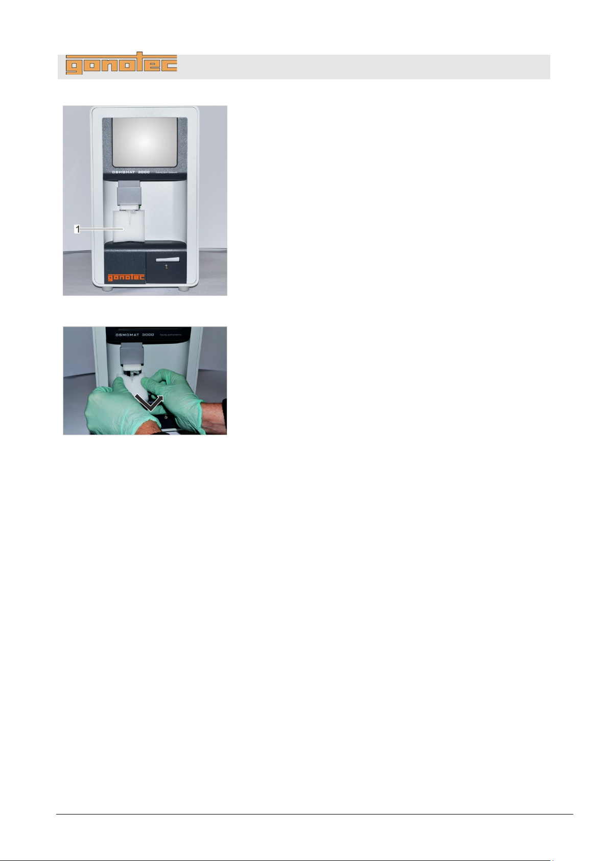
Fig.
3. Remove transport safety device (
sensor. Proceed as follows:
Fig.
4. Carefully pull transport safety device down and
remove.
Personnel:
Lab supervisor
1
Connect power plug to device.
2
Connect power cable to a properly grounded power socket.
3
Connect a PC via RS232 or USB (if applicable).
4
Connect a barcode reader (if applicable).
24: Transport safety device
Installation
Fig. 24/1) from temperature
pull forward to
25: Remove transport safety device
5.3 Connect device
.
.
.
.
Version 1.22 1/6/2016 47
Page 48
OSMOMAT 3000
basic
// OSMOMAT 3000
Personnel:
Lab supervisor
1. Complete all activities for installation and connection of the
device.
2. Verify that the connections at the rear s ide of the devic e
are
3
Check the elevator for ease of movement.
If necessary, grease the elevator guide (
elevator
4
Power up device on rear side using on/off switch.
Fig.
Fig.
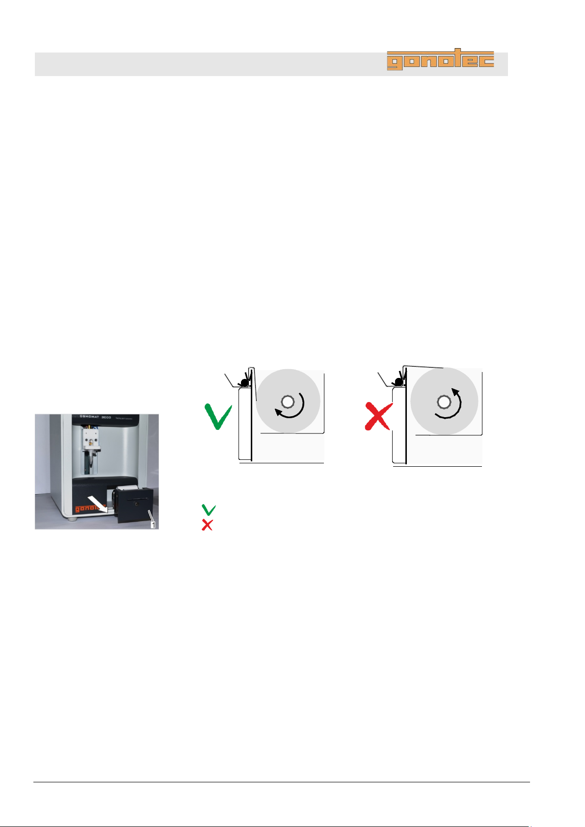
Correct feed direction
Incorrect feed direction
5. Check feed direction of paper roll. Open printer (
by
direction of paper roll with f
6
Check cryst
Open the Adjust Needle menu
Options
Setup
6 Setup
6.1 Check printer (Option D)
(does not apply to OSMOMAT 3000basic)
.
.
secure.
” on page 100).
chapter 9.4 “Lubricate
27: Paper roll feed direction
26: Pull out printer
Fig. 26/1)
pulling on silver knob (magnetic latch) and compare feed
eed direction shown in Fig. 27.
6.2 Check free movement of steel needle
.
-needle for free movement.
(Start menu Settings Lab
Maintenance Adjust Needle).
48 Version 1.22 1/6/2016
Page 49
OSMOMAT 3000
basic
// OSMOMAT 3000
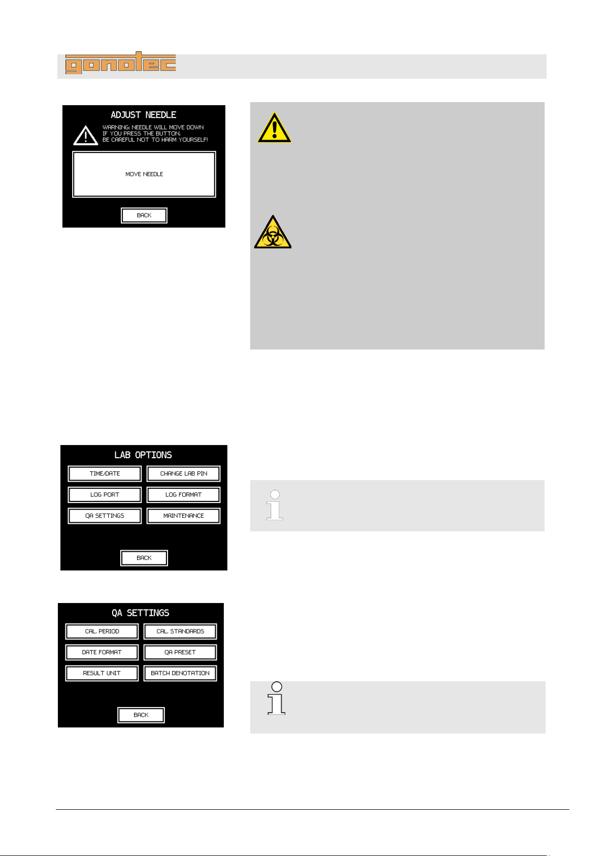
Fig.
7
Tap
Tap
Select calibration procedure
Fig.
8
Open
In the Start menu, tap
See
Fig.
9
Open the menu for configuring the lab options.
To configure the calibration interval, tap
To select the calibration standards you are using, tap
Cal.
To set up the calibration method, tap
OSMOMAT 3000
Cal.
not
28: Adjust Needle menu
6.3 Set calibration defaults
Setup
.
Move Needle and ensure that the cryst-needle moves freely.
Back to complete the check.
CAUTION!
Risk of injury from cryst-needle!
The tip of the cryst-needle is exposed. Movement of
the cryst-needle can cause needle puncture injuries.
- Always keep your hands and fingers clear from
the area underneath the cryst-needle.
WARNING!
Risk of infection due to sample residue and in
case of inadequate hygiene, disinfection, and
sterilization procedures!
Exposure to sample residue in non-cleaned, nonsterilized, or non-disinfected components results in
an elevated risk of infection.
- Wear lab gloves during any kind of work.
- Observe all local regulations regarding hygiene,
disinfectant cleaning, and sterilization.
29: Lab Options menu
30: QA Settings menu
.
the menu for configuring the lab options.
Settings Lab Options.
The menu can be protected with a lab supervisor
password.
QA Settings to learn more about calibration settings.
.
Cal. Period.
Standards.
QA Preset.
basic:
Period and Cal. Standards selections are
available
Version 1.22 1/6/2016 49
Page 50
OSMOMAT 3000
basic
// OSMOMAT 3000
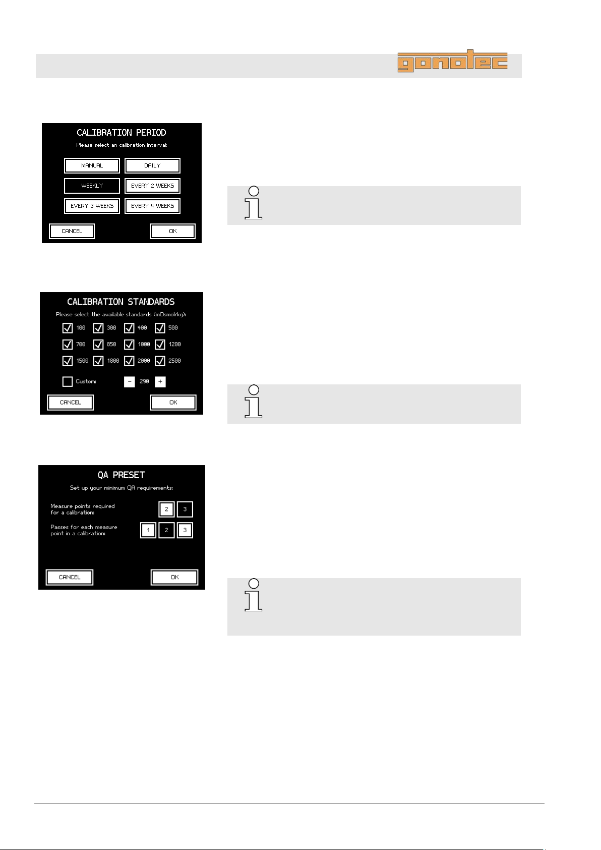
Configure calibration interval
Fig.
10
Select a calibration interval.
When selecting
calibration (not recommended).
OSMOMAT 3000
Selection not available
Select calibration standards
Fig.
11. Specify the allowed calibrat ion points . T he y should be clos e to
the expected measurement values.
A calibration point (
in
Enter the values in mOsmol/kg.
OSMOMAT 3000
Selection not available
Set up calibration method
Fig.
12
Select the calibration method:
13. Select the number of measurements to be performed for each
calibration medium (distilled water and calibration standard).
The system calculates the calibration values from the mean value
of these
Setup
31: Configure calibration interval
.
Manual, the device does not prompt you for
basic:
Custom) can be freely selected by the user
increments of 10 and enabled or disabled for selection.
32: Select calibration standards
33: Set up calibration method
basic:
.
2-point: Select 2-point calibration
3-point: Select 3-point calibration
measurements.
The number of measurements for each calibration
point does not affect the linearity or reproducibility
of the measurement system.
They are only used to arrive at the mean value.
50 Version 1.22 1/6/2016
Page 51
OSMOMAT 3000
basic
// OSMOMAT 3000
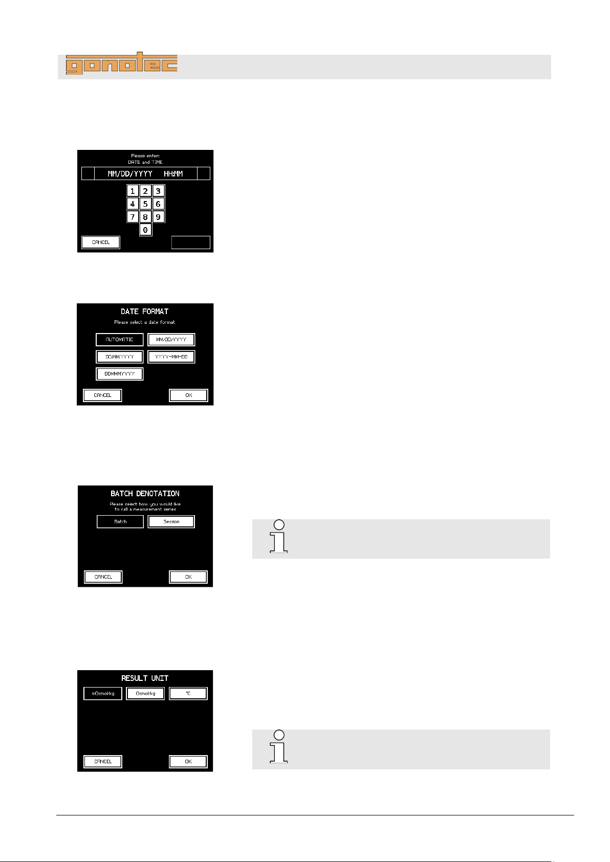
Set date and time
Fig.
14
Enter date and time as follows:
DD
MM
YYYY
HH
MM
Set date
Fig.
15
Select the date format required:
DD
MM
MMM
YYYY
If AUTOMATIC is
the
Set measurement series name
Fig.
16
Select the name for your measurement series.
OSMOMAT 3000
Selection not available
Set result unit
Fig.
17
Select the unit for the measurement results:
-
-
OSMOMAT 3000
Selection not
6.4 Date Time
34: Set date and time
format
35: Select date format
.
Setup
– Day, two digits [01…31]
– Month, two digits [01…12]
– Year, four digits [2014]
– Hour, t wo digits [00…23]
– Minutes, two digits [00…59]
.
– Day, two digits [01…31]
– Month, two digits [01…12]
– Month [Jan…Dec]
– Year, four digits [2014]
selected the date format is based on
language selected.
6.5 Measurement series name
36: Measurement series name
6.6 Result Unit
37: Select unit
.
basic:
.
mOsmol/kg
Osmol/kg
°C
basic:
available
Version 1.22 1/6/2016 51
Page 52
OSMOMAT 3000
basic
// OSMOMAT 3000
Electrical current
Risk of infection
Operation
7 Operation
DANGER!
Risk of death due to electrical current on device!
Contact with energized parts of the device results in
immediate risk of death due to electric shock. Damage
to the insulation of individual components can cause
risk of death.
- Only have qua lifie d per sonnel perform repair and
maintenance work on the device.
- If the insulation is damaged, immediately disconnect
the power plug and schedule a repair.
- Always route the power cable so it is not subject to
stress and cannot be bent, pinched, or rolled over
and is not exposed to liquids or heat.
- Ensure easy access to the power socket at all times.
- Keep energized parts away from liquids. Otherwise,
shorts may occur.
WARNING!
Risk of infection due to sample residue and in case
of inadequate hygiene, disinfection, and sterilization
procedures!
Exposure to sample residue in non-cleaned, nonsterilized, or non-disinfected components results in
an elevated risk of infection.
- Wear lab gloves during any kind of work.
- Observe all local regulations regarding hygiene,
disinfection, and sterilization.
52 Version 1.22 1/6/2016
Page 53
OSMOMAT 3000
basic
// OSMOMAT 3000
Personnel:
Safety gear:
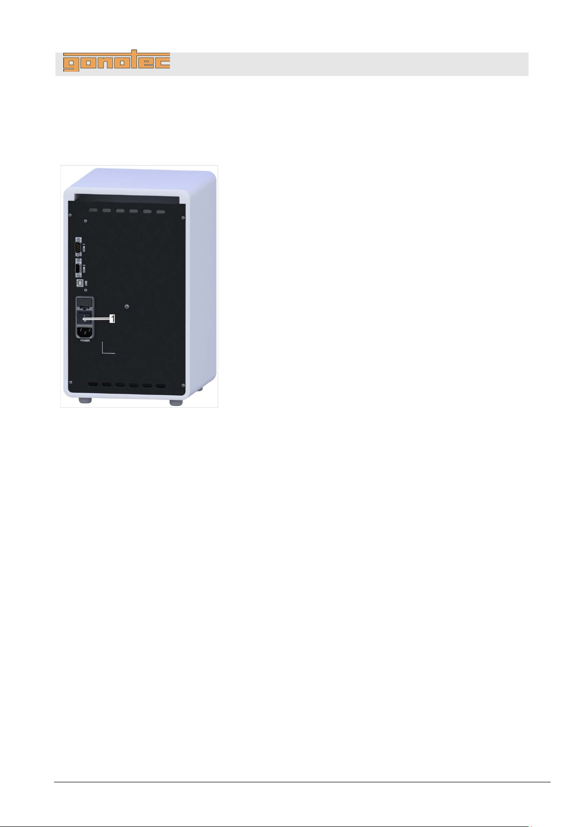
Fig.
1
Power up device on rear side using on/off switch (
7.1 Power up device
Operation
User
Disposable lab gloves
.
Fig. 38/1).
38: Power up device
Version 1.22 1/6/2016 53
Page 54
OSMOMAT 3000
basic
// OSMOMAT 3000
Configure language
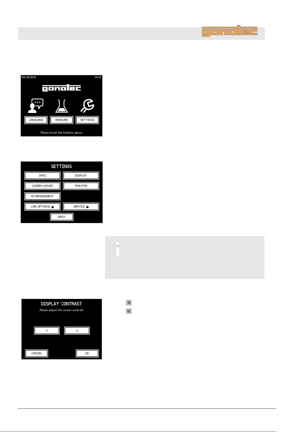
Fig.
Tap
Overview
Fig.
Tapping
The Settings menu lets the user configure the following settings:
Configure screen contrast
Fig.
1
Tap
Tap
Operation
7.2 Modify user preferences
39: Select language
40: Overview of user preferences
Language and select a language.
Settings on the Start menu opens the Settings menu.
Info: Shows the version of the device software
Display: Configure screen contrast
Screen saver: Configure screen saver
Printer: Activate paper feed (Option D only)
(does not apply to OSMOMAT 3000basic)
ID Management: Set ID for sample and series measurements
(does not apply to OSMOMAT 3000basic)
The Lab Options option is protected with the lab
supervisor password.
The Service option is protected with the service
password. Modifications have to be requested
by contacting the manufacturer.
.
to increase contrast.
to decrease contrast.
41: Configure screen contrast
54 Version 1.22 1/6/2016
Page 55
OSMOMAT 3000
basic
// OSMOMAT 3000
Configure screen saver
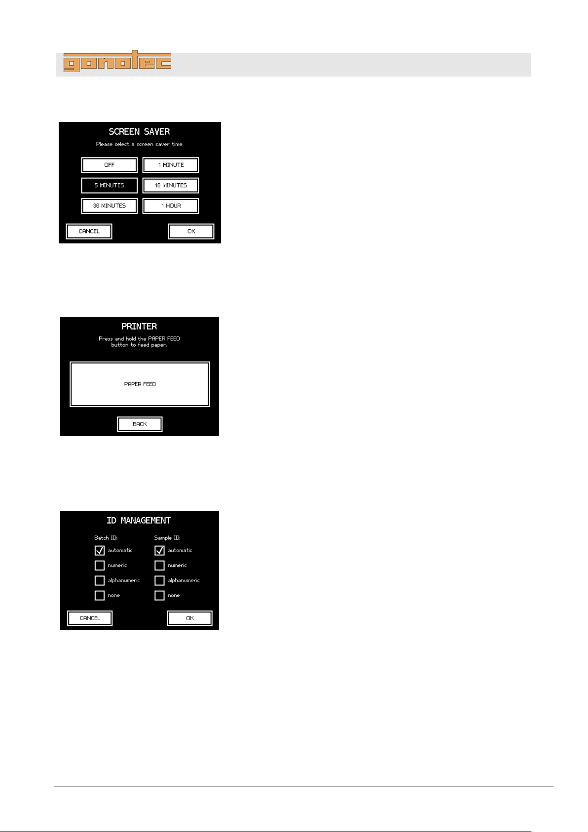
Fig.
1. Select the duration after which the system activates the screen
saver.
Tapping
Activate paper feed
(does not apply to
OSMOMAT
Fig.
1
Option D only:
Tap
The paper feed of the printer is activated briefly.
Tap
Set sample and batch ID
(does not apply to
OSMOMAT
Fig.
1. Select the settings for the IDs for series measurements
(
options are available:
42: Configure screen saver
3000basic)
Operation
OFF will never activate the screen saver.
.
Paper Feed.
43: Activate paper feed
3000basic)
44: Set sample and batch ID
Back to exit the menu.
Batch ID) and individual samples (Sample ID). The following
automatic: The samples and the charge IDs are assigned
running numbers automatically. The counter resets daily.
The counter for the individual samples in a series
measurement resets when starting a new series
measurement.
numeric: Numeric IDs are assigned manually. During
measurements, the system prompts the user to enter the
numeric ID of the sample or charge using the virtual keyboard.
alphanumeric: Alphanumeric IDs are assigned manually.
During measurements, the system prompts the user to enter
the alphanumeric ID of the sample or charge using the virtual
keyboard.
none: Do not use IDs for samples and batches.
Version 1.22 1/6/2016 55
Page 56
OSMOMAT 3000
basic
// OSMOMAT 3000
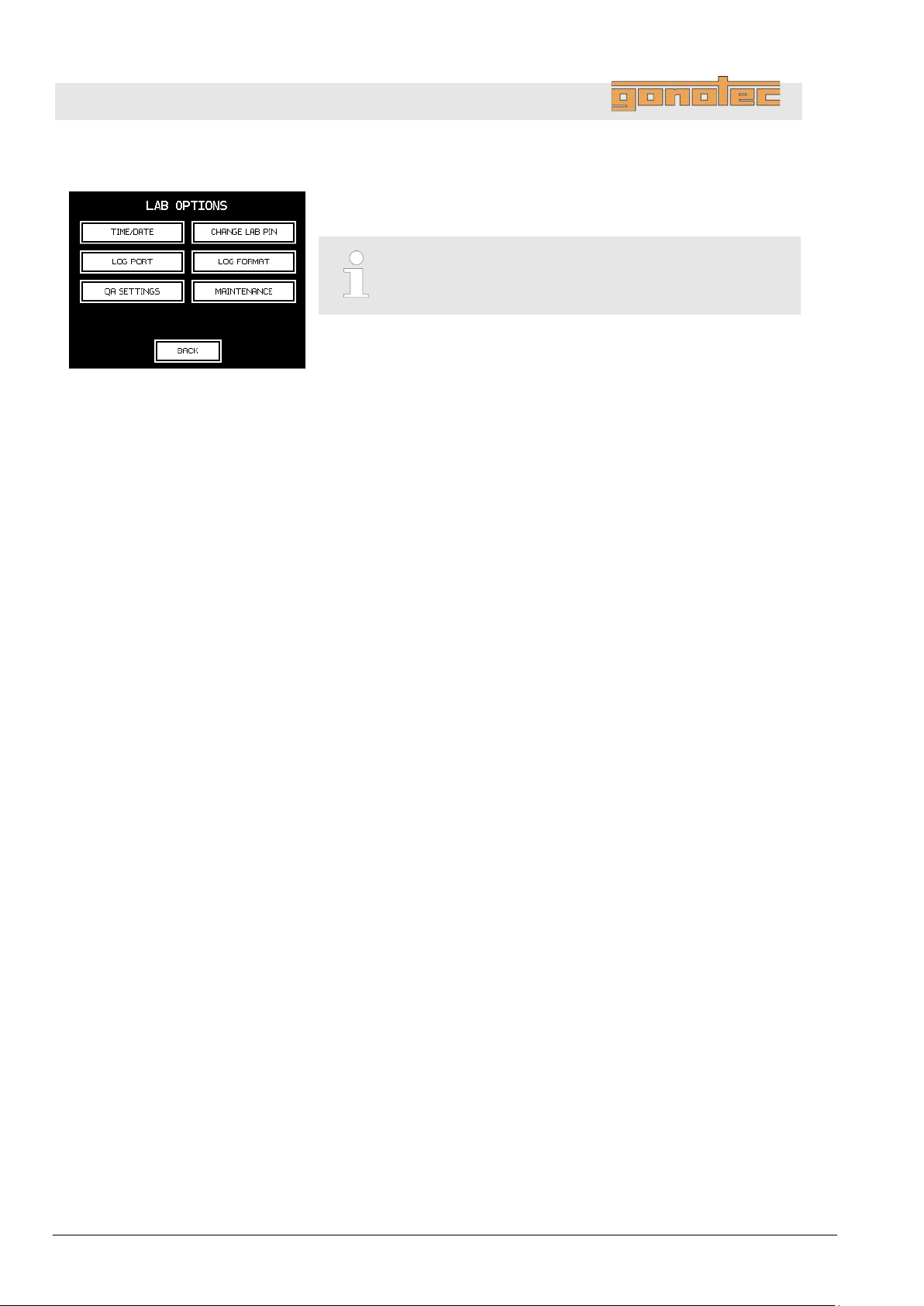
Laboratory options
Fig.
Tapping
menu.
The
Operation
45: Overview of lab settings
Lab Options in the Settings menu opens the Lab Options
The Lab Options option is protected with the lab
supervisor password.
Lab Options menu lets the user configure the following settings:
Time/Date: Set time and date
Change Lab PIN: Change PIN for access to lab options
Log Port: Set log port ( chapter 3.6.1)
(does not apply to OSMOMAT 3000basic)
Log Format: Set log format ( chapter 3.6.2)
(does not apply to OSMOMAT 3000basic)
QA Settings: Additional configuration settings ( page 49)
(does not apply to OSMOMAT 3000basic)
Maintenance: Options for maintenance and troubleshooting
(
chapter 8.4)
56 Version 1.22 1/6/2016
Page 57
OSMOMAT 3000
basic
// OSMOMAT 3000
Personnel:
Safety gear:
Materials:
Fig.
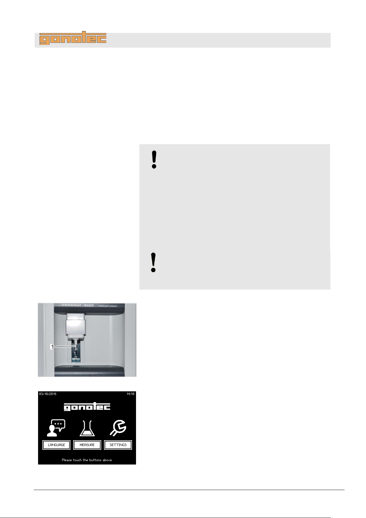
1. Clean temperature sensor (
paper towel.
Fig.
2. Tap
If the operating time of the device is less than 3
a
7.3 Measure individual samples
Operation
User
Disposable lab gloves
Soft, lint-free paper tissue
Pipette
Measurement vessel
Sample
NOTE!
Impaired reproducibility of measurement due to
incorrect measurement vessels!
Repeated use of the measurement vessels and use of
incorrect consumables cannot guarantee reproducible
measurement results.
- Always use a clean and un us ed m eas ur em ent
vessel for every measurement.
- Only use measurement vessels supplied by
Gonotec GmbH.
- Never use centrifuge tubes or reaction vessels.
NOTE!
Risk of incorrect measurement resulti n g from
the presence of air bubbles in the sample!
The sample must be pipetted without air bubbles.
Fig. 46/1) using a soft, dry, lint-free
46: Clean temperature sensor
Measure on the Start menu (Fig. 47).
wait screen for ice formation is displayed (Fig. 48).
minutes,
47: Start menu
Version 1.22 1/6/2016 57
Page 58
OSMOMAT 3000
basic
// OSMOMAT 3000
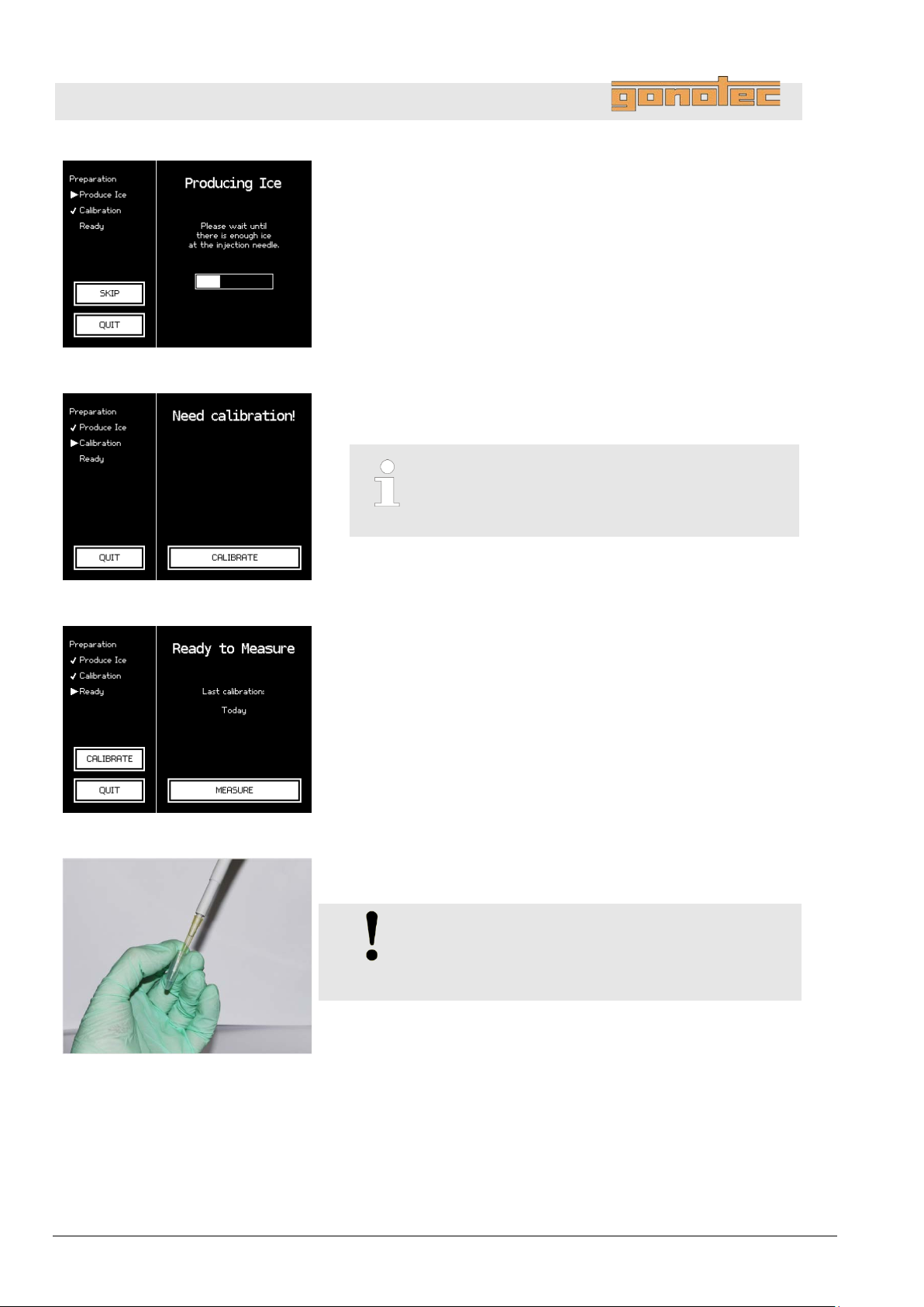
Fig.
3
Wait until ice forms on the cryst
After successful ice formation, a calibration prompt (
or
(depending on the configured calibration interval).
Fig.
4
If necessary, calibrate device (
The device is ready.
Fig.
5. Tap
The measurement menu (
Fig.
6. Pipette a sample volume of 50µl (15µl for Option
an
Operation
48: Ice formation
.
-needle (Fig. 48).
Fig. 49)
the Ready to Measure screen (Fig. 50) is displayed
.
Fig. 49).
Chapter 7.5 “Calibrate device” on page 65.
Calibration cannot be skipped.
The calibration interval is defined by the lab
supervisor (does not apply to OSMO MAT 300 0basic).
49: Calibrate device
50: Device is ready for measurement
Measure (Fig. 50).
Fig. 53) opens.
M) into
unused and clean measurement vessel (Fig. 51).
NOTE!
Risk of incorrect measurement resulti n g from
the presence of air bubbles in the sample!
The sample must be pipetted without air bubbles.
51: Pipette sample
58 Version 1.22 1/6/2016
Page 59
OSMOMAT 3000
basic
// OSMOMAT 3000
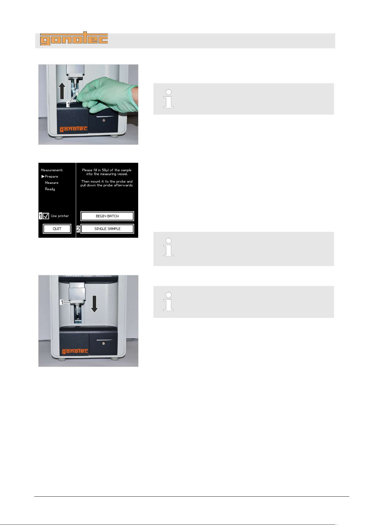
Fig.
7. Position measurement vessel on temperature sensor with cover
facing front (
Fig.
8. Option
(does not apply to OSMOMAT 3000
Tap
the measurement results to a printer. Make
is
9. To start the measurement, tap
If necessary, enter the sample ID using the virtual keyboard.
Fig.
10
Move elevator (
The sample measurement is performed automatically.
Pay
52: Position measurement vessel
Operation
Fig. 52/1).
The measurement vessel is securely attached to
the temperature sensor when it clicks into place.
D only:
basic)
Use printer on the measurement menu (Fig. 53/1) to output
sure that the printer
ready.
Single Sample (Fig. 53/2).
53: Measurement menu
54: Move elevator down
The sample ID can be pre-defined in the user
preferences. In this case, the system assigns
the sample ID automatically ( page 55)
.
Fig. 54/1) down.
Moving the elevator up during the measurement
will abort the measurement.
attention to the displays on the touchscreen.
Version 1.22 1/6/2016 59
Page 60
OSMOMAT 3000
basic
// OSMOMAT 3000
Fig.
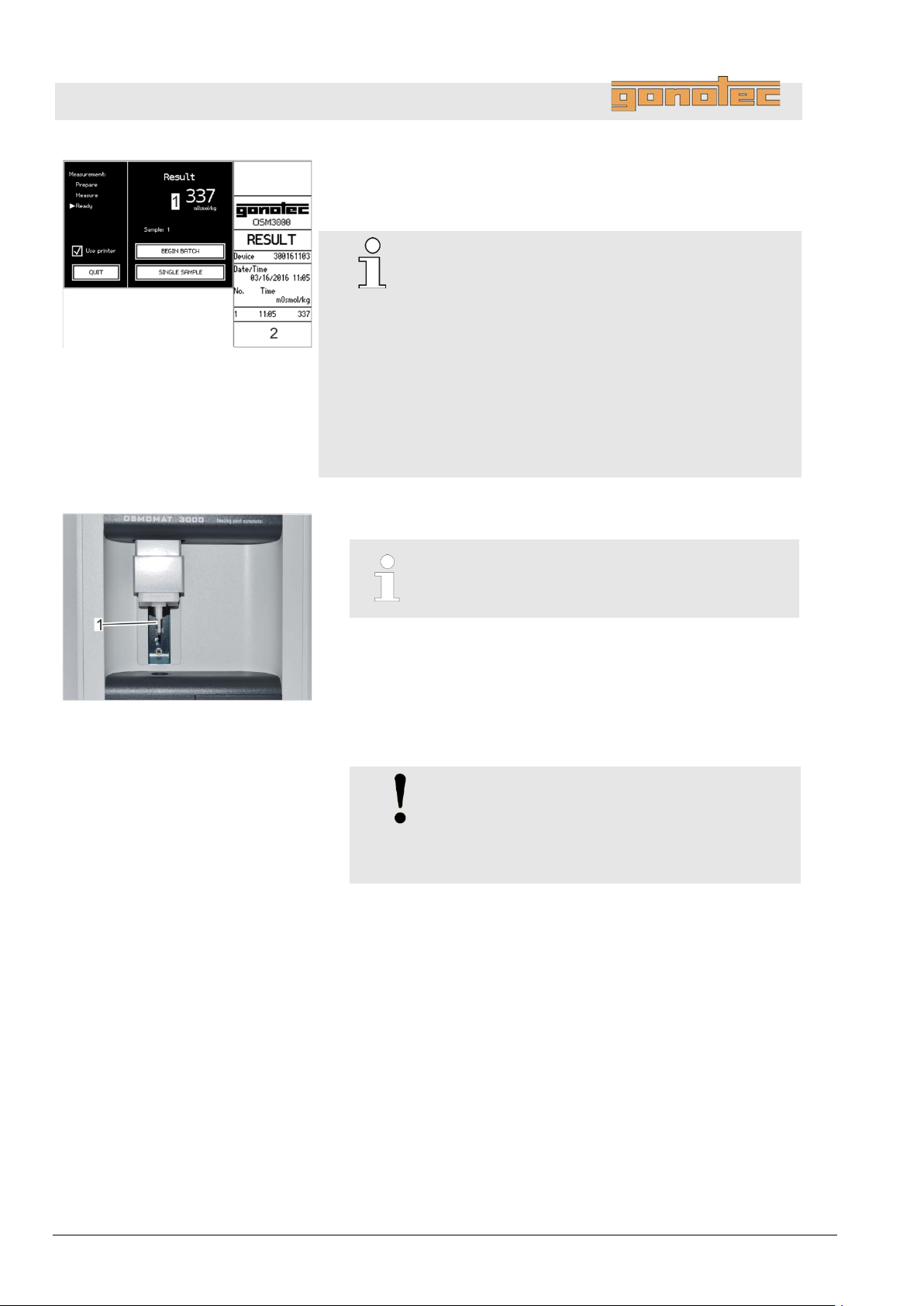
The measurement result displays on the touchscreen
(
Fig.
11
Move elevator up.
12
Remove measurement vessel from temperature sensor.
Dispose of measurement
regulations.
13. Clean temperature sensor (
paper
Operation
55: Measurement
Fig. 55/1) and, if applicable, prints (Fig. 55/2) (Option D).
Reproducibility:
#
±2 digits in the measurement range
[0..400] mOsmol/kg
#
±0.5% in the measurement range
.
[400..1500] mOsmol/kg
#
±1.0% starting with 1500 mOsmol/kg
Option M (15µl):
#
±6 digits [0..300] mOsmol/kg
#
±2.0% [300..3000] mOsmol/kg
56: Clean temperature sensor
Moving the elevator up during the measurement will
abort the measurement.
.
vessel and sample according to local
Fig. 56/1) using a soft, dry, lint-free
towel.
NOTE!
Risk of carryover!
Failure to clean the temperature s ens or
immediately following measurement can result
in carryover and incorrect measurement results.
60 Version 1.22 1/6/2016
Page 61
OSMOMAT 3000
basic
// OSMOMAT 3000
Personnel:
Safety gear:
Materials:
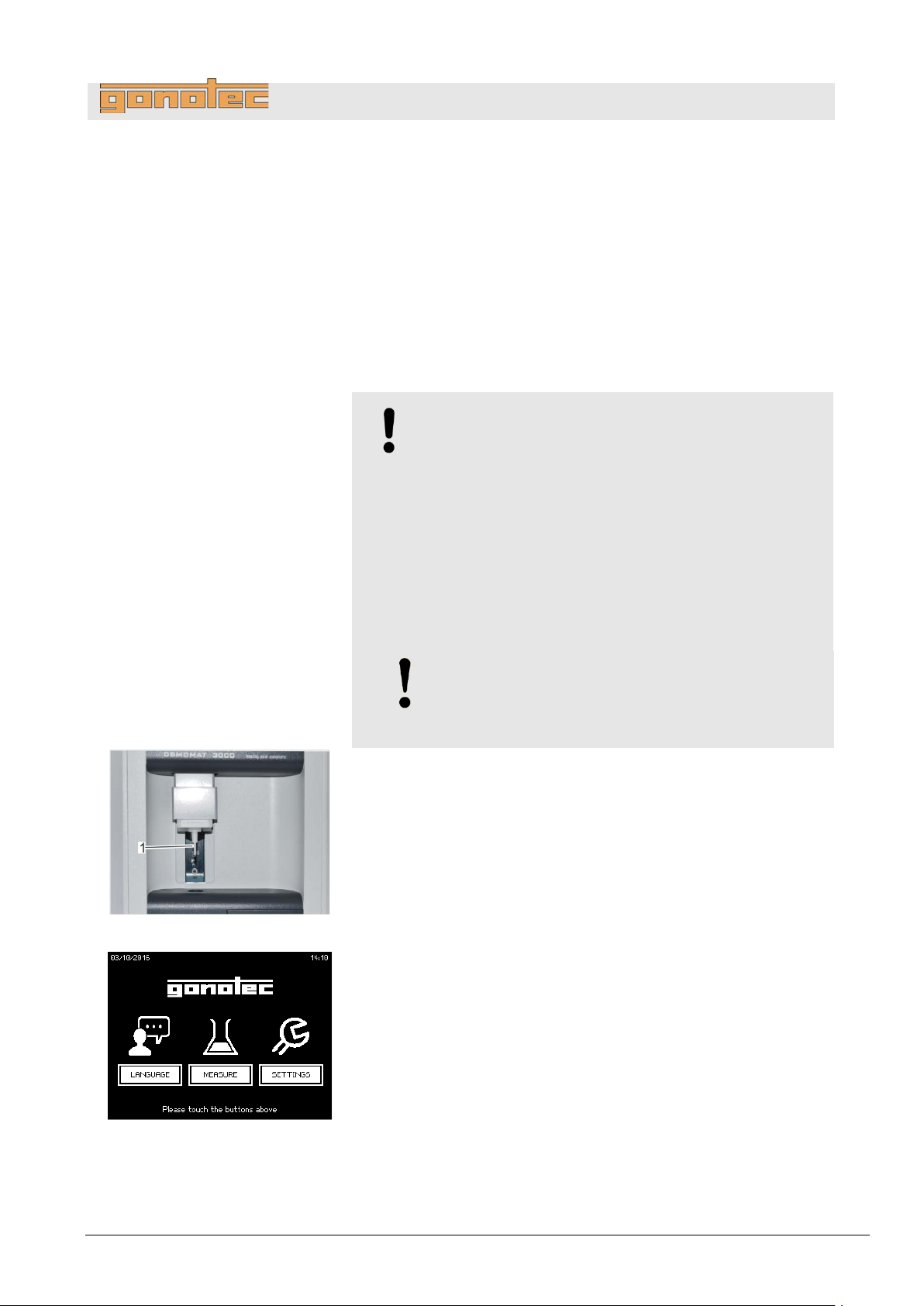
Fig.
1. Clean temperature sensor (
paper towel.
Fig.
2. Tap
If the operating time of the device is less than 3
a
7.4 Batch/series measurement
(does not apply to OSMOMAT 3000
Operation
basic)
User
Disposable lab gloves
Soft, lint-free paper tissue
Pipette
Measurement vessel
Samples
NOTE!
Impaired reproducibility of measurement due to
incorrect measurement vessels!
Repeated use of the measurement vessels and use of
incorrect consumables cannot guarantee reproducible
measurement results.
- A lways use a clean and unused measurement vessel
for every measurement.
- Only use measurement vessels supplied by
Gonotec GmbH.
- Never use centrifuge tubes or reaction vessels.
NOTE!
Risk of incorrect measurement resulti n g from
the presence of air bubbles in the sample!
The sample must be pipetted without air bubbles.
Fig. 57/1) using a soft, dry, lint-free
57: Clean temperature sensor
Measure on the Start menu (Fig. 58).
minutes,
wait screen for ice formation is displayed (Fig. 59).
58: Start menu
Version 1.22 1/6/2016 61
Page 62
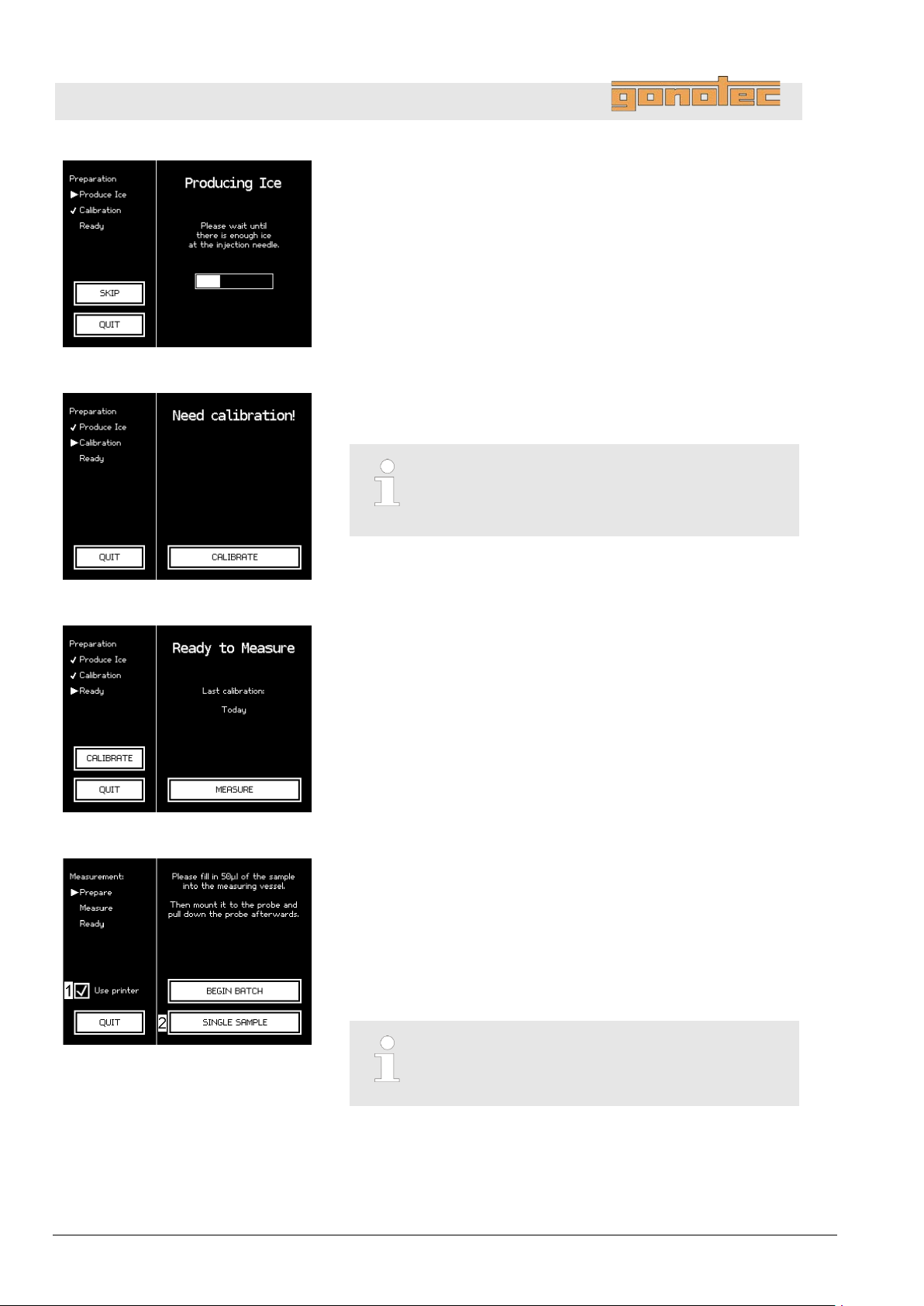
OSMOMAT 3000
basic
// OSMOMAT 3000
Fig.
3
Wait until ice forms on the cryst
After successful ice formation, a calibration prompt (
or
(depending on the configured calibration interval).
Fig.
4
If necessary, calibrate device (
The device is ready.
Fig.
5. Tap
The measurement menu (
Fig.
6
Option D only:
Tap
the measurement results to a printer.
Make sure that the printer is ready.
7. To start a series measurement, tap
8
Enter the batch ID.
Operation
59: Ice formation
.
-needle (Fig. 59).
Fig. 60)
the Ready to Measure screen (Fig. 61) is displayed
.
Fig. 60).
Chapter 7.5 “Calibrate device” on page 65.
Calibration cannot be skipped.
The calibration interval is defined by the lab
supervisor (does not apply to OSMO MAT 300 0basic).
60: Calibrate device
61: Device is ready for measurement
Measure (Fig. 61).
Fig. 62) opens.
.
Use printer on the measurement menu ( Fig. 62/1) to output
Begin Batch (Fig. 62/2).
.
62: Measurement menu
62 Version 1.22 1/6/2016
The batch ID can be pre-defined in the user
preferences. In this case, the system assigns
the batch ID automatically ( page 55)
Page 63
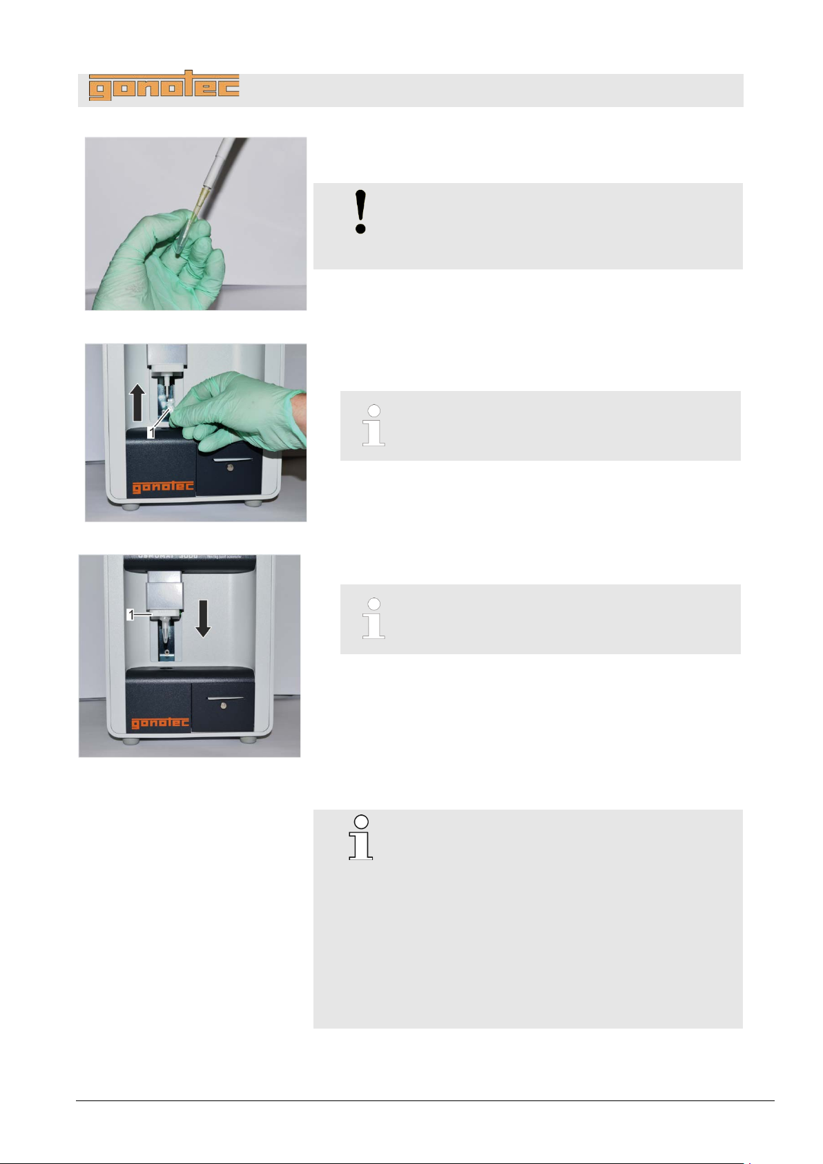
OSMOMAT 3000
basic
// OSMOMAT 3000
Fig.
9. Pipette a sample volume of 50µl (15µl for
an
Fig.
10. Position measurement vessel on temperature sensor with cover
facing front (
Fig.
11
Move elevator (
The sample measurement is performed automatically.
Pay
The touchscreen shows the measurement result for
the
Option D:
The measurement result prints.
63: Pipette sample
Operation
Option M) into
unused and clean measurement vessel (Fig. 63).
NOTE!
Risk of incorrect measurement resulti n g from
the presence of air bubbles in the sample!
The sample must be pipetted without air bubbles.
Fig. 64/1).
The measurement vessel is securely attached to
the temperature sensor when it clicks into place.
64: Position measurement vessel
65: Move elevator down
.
Fig. 65/1) down.
Moving the elevator up during the measurement
will abort the measurement.
attention to the displays on the touchscreen.
current sample.
Reproducibility:
#
±2 digits in the measurement range
[0..400] mOsmol/kg
#
±0.5% in the measurement range
[400..1500] mOsmol/kg
#
±1.0% starting with 1500 mOsmol/kg
Option M (15µl):
#
±6 digits [0..300] mOsmol/kg
#
±2.0% [300..3000] mOsmol/kg
Version 1.22 1/6/2016 63
Page 64
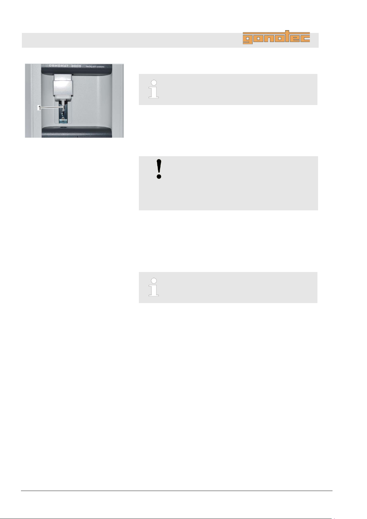
OSMOMAT 3000
basic
// OSMOMAT 3000
Fig.
12
Move elevator up.
13
Remove measurement vessel from temperature sensor.
Dispose of measurement vessel and sample according to local
regulations.
14. Clean temperature sensor (
paper towel.
15. Start the measurement of the new sample by repeating the work
steps starting with step
To complete the series measurement, tap
Option D:
Completing the
the
Operation
66: Clean temperature sensor
.
Moving the elevator up during the measurement
will abort the measurement.
.
Fig. 66/1) using a soft, dry, lint-free
NOTE!
Risk of carryover!
Failure t o c l ea n t h e temperature s e ns or
immediately following measurement can result
in carryover and incorrect measurement
results.
printing operation.
Exiting the measurement menu (by pressing Exit)
will also quit the series measurement.
9.
Complete batch.
series measurement also completes
64 Version 1.22 1/6/2016
Page 65
OSMOMAT 3000
basic
// OSMOMAT 3000
Calibration methods
Depending on the pre
measurement menu will automatically show a calibration prompt
(
The device is calibrated using one of the following calibration
methods:
2
water (zero point calibration) and one calibration standard.
3
water (zero point calibration) and two calibration standards.
The calibration method, the calibration standards used for ca
and the calibration interval are defined by the lab supervisor during
start
Calibrate device
Personnel:
Safety gear:
Materials:
7.5 Calibrate device
Operation
-defined calibration interval, opening the
Fig. 49). Calibration can also be started manually (Fig. 50).
2-point calibration: Calibration using distilled water and
a calibration standard or
3-point calibration: Calibration using distilled water and two
calibration standards
-point calibration means that the device is calibrated using distilled
-point calibration means that the device is calibrated using distilled
libration,
-up ( chapter 6.3 “Set calibration defaults” on page 49).
User
Soft, lint-free paper tissue
NOTE!
Impaired reproducibility of measurement due to
incorrect measurement vessels!
Repeated use of the measurement vessels and use of
incorrect consumables cannot guarantee reproducible
measurement results.
- Always use a clean and unused measurement vessel
- Only use measurement vessels supplied by
- Never use centrifuge tubes or reaction vessels.
Disposable lab gloves
Pipette
Distilled wate r
Calibration standard(s) (e.g. 300 mOsmol/kg)
Ampoule opener
Measurement vessels
for every measurement.
Gonotec GmbH.
Version 1.22 1/6/2016 65
Page 66
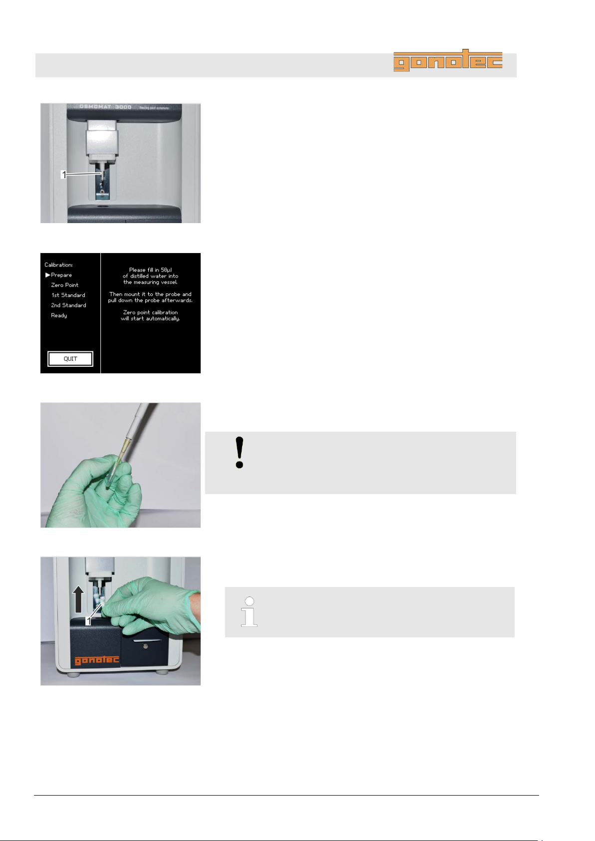
OSMOMAT 3000
basic
// OSMOMAT 3000
Fig.
1. Clean temperature sensor (
paper towel.
Fig.
2
Follow the instructions on the touchscreen.
Fig.
3. Pipette a distilled water volume of 50µl (15µl for Option
an
Fig.
4. Position measurement vessel on temperature sensor with cover
facing front (
Operation
67: Clean temperature sensor
Fig. 67/1) using a soft, dry, lint-free
.
68: Perform zero point calibration
69: Pipette distilled water
M) into
unused and clean measurement vessel (Fig. 69).
NOTE!
Risk of incorrect measurement resulti n g from
the presence of air bubbles in the sample!
The sample must be pipetted without air bubbles.
Fig. 70/1).
The measurement vessel is securely attached to
the temperature sensor when it clicks into place.
70: Position measurement vessel
66 Version 1.22 1/6/2016
Page 67
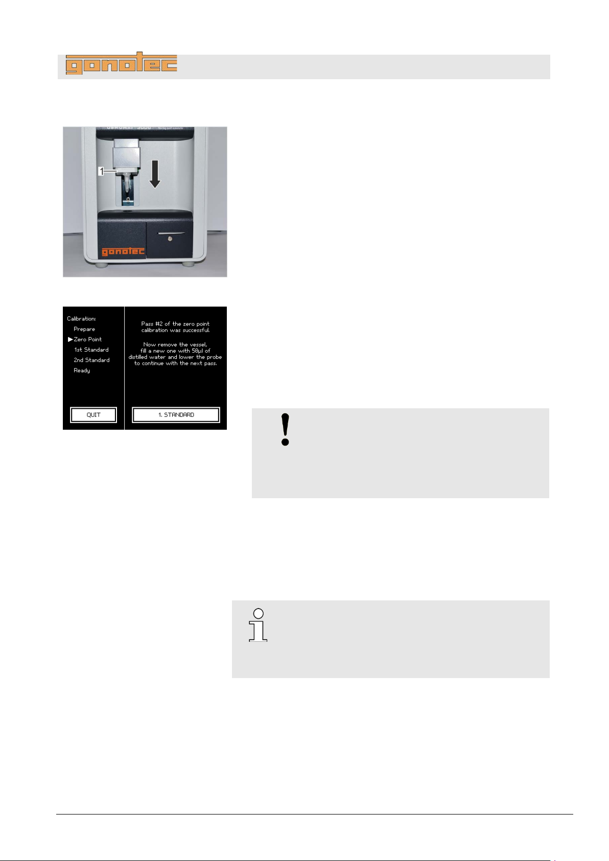
OSMOMAT 3000
basic
// OSMOMAT 3000
Fig.
5
Move elevator (
Zero point calibration starts automatically.
Zero point calibration is
Pay
Fig.
standard
6
Move elevator up.
7
Remove measurement vessel
Dispose of measurement vessel and sample according to local
regulations.
8. Clean temperature sensor (
paper towel.
9. Repeat
calibration point specified in the calibration defaults
(max.
10
Following successful zero point calibration, tap
(
Perform zero point calibration
71: Move elevator down
Operation
.
attention to the displays on the touchscreen.
.
.
Fig. 71/1) down.
performed automatically.
from temperature sensor.
72: Calibrate device using calibration
Fig. 67/1) using a soft, dry, lint-free
NOTE!
Risk of carryover!
Failure t o c l ea n t h e temperature s e ns or
immediately following measurement can result
in carryover and incorrect measurement
results.
steps 3 through 8 until the number of measurements per
3) is reached.
.
1st Standard
Fig. 72) to start calibration using the first calibration standard.
Successful calibration means that it was possible to
measure the sample without errors.
This is not a plausibility check, which is not perform ed
until the entire calibration sequence is completed in
measurement mode ( page 103).
( page 50)
Version 1.22 1/6/2016 67
Page 68
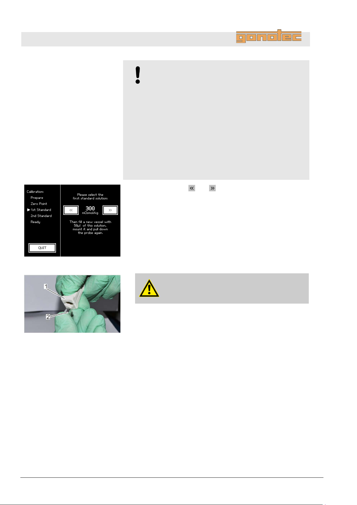
OSMOMAT 3000
basic
// OSMOMAT 3000
Calibrate device using calibration
standard
Fig.
11. Use the arrow keys
to be used.
Fig.
12
Use the ampoule opener (
containing the calibration standards (
Operation
NOTE!
Impaired reproducibility of measurement due to
improper handling of calibration standards!
Improper handling and storage of the calibration
standards included with the delivery negatively affects
the measurement accuracy of the device.
- Always observe the stability of the calibration
standards (max. 0.5h at 22°C ambient temperature).
- Never use opened ampoules twice or mix them
together.
- Never fr ee ze opened ampoules.
- Do not use the calibration standards past their
expiration date.
and to select the calibration standard
73: Select calibration standard
74: Open ampoule
.
WARNING!
Risk of injury at ampoule breaking points!
Fig. 74/2) to open the ampoules
Fig. 74/1).
68 Version 1.22 1/6/2016
Page 69
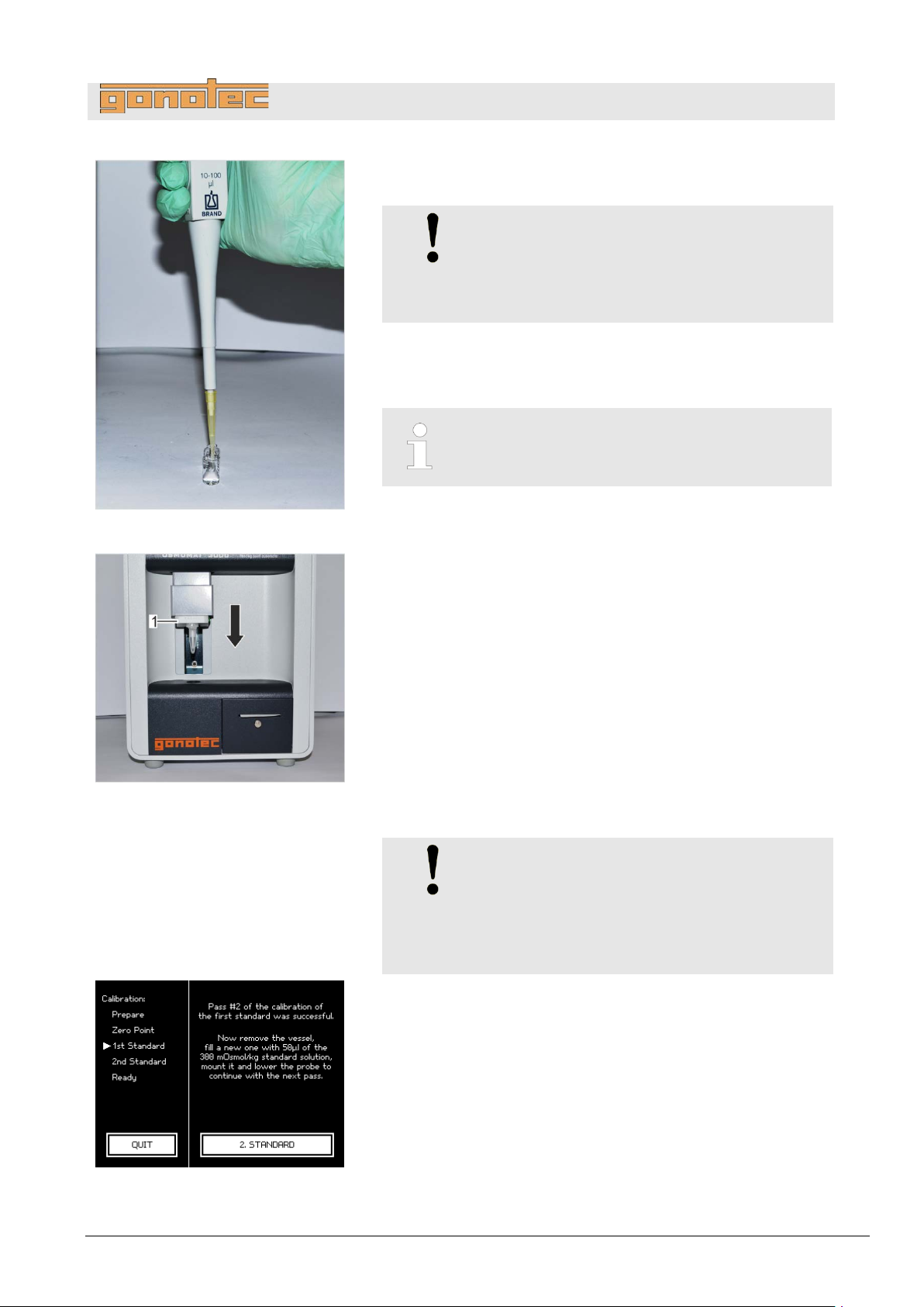
OSMOMAT 3000
basic
// OSMOMAT 3000
Fig.
13. Pipette a calibration standard volume of 50µl (15µl for Option
into a
14. Position
facing front.
Fig.
15
Move
Calibration starts automatically.
Calibration using the calibration standard is performed
automatically. Pay attention
touchscreen.
16
Move elevator up.
17
Remove measurement vessel from temperature sensor.
Dispose of measurement vessel and sample according to local
regulations.
18. Clean temperature sensor (
paper towel.
Fig.
19. Repeat
per calibration point specified in the calibration defaults
(
For a 3
another calibration standard.
75: Pipette calibration standard
Operation
M)
clean and unused measurement vessel (Fig. 75).
NOTE!
Risk of incorrect measurement resulti n g from
the presence of air bubbles in the sample!
The sample must be pipetted without air
bubbles.
measurement vessel on temperature sensor with cover
The measurement vessel is securely attached to
the temperature sensor when it clicks into place.
76: Move elevator down
.
elevator (Fig. 76/1) down.
to the displays on the
.
.
Fig. 76/1) using a soft, dry, lint-free
NOTE!
Risk of carryover!
Failure t o c l ea n t h e temperature s e ns or
immediately following measurement can result
in carryover and incorrect measurement
results.
steps 13 through 18 until the number of measurements
page 50) (max. 3) is reached.
77: Second calibration standard
-point calibration, repeat steps 10 through 19 using
Version 1.22 1/6/2016 69
Page 70
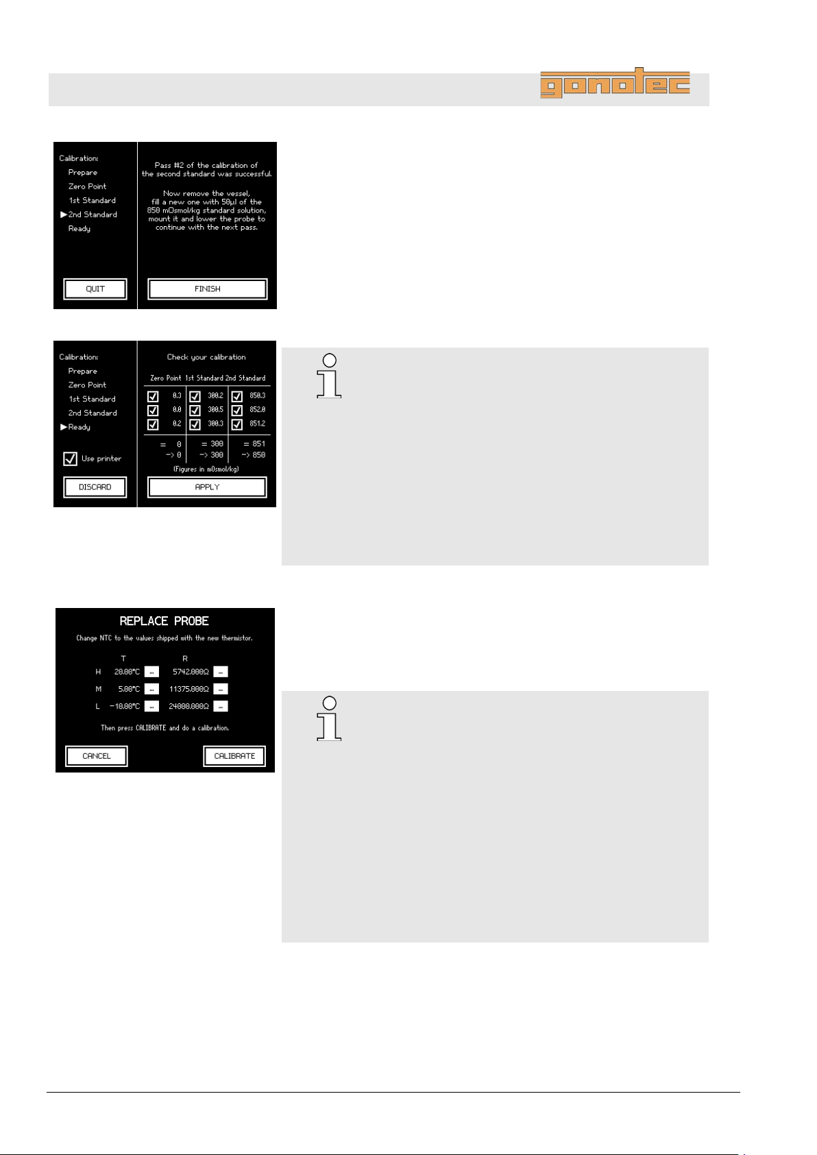
OSMOMAT 3000
basic
// OSMOMAT 3000
Fig.
Fig.
Calibration can be completed after performing the number
of
calibration point
The system now shows the calibration results (
The
the individual measurements.
This is the result of a 3
20
Verify the calibration
If necessary, tap the individual measurement values to ignore
them during mean value calculation.
21. Tap
The device is now calibrated.
22. Verify reproducibility (
or continue with your measurements (
on
Fig.
Operation
78: Complete calibration
79: Calibration results
runs specified in the calibration defaults for the very last
(Fig. 78).
Fig. 79).
resulting osmolalities are calculated as the mean across
-point calibration.
.
results.
Reproducibility:
#
±2 digits in the measurement range
[0..400] mOsmol/kg
#
±0.5% in the measurement range
[400..1500] mOsmol/kg
#
±1.0% starting with 1500 mOsmol/kg
Option M (15µl):
#
±6 digits [0..300] mOsmol/kg
#
±2.0% [300..3000] mOsmol/kg
80: Replace probe
Apply to complete the calibr ati on.
page 103)
sample measurement
page 54, series measurement on page 61).
Note regarding 2-point calibration:
For a 2-point calibration, the measurement accuracy
of the device depends on the correct internal
calibration of the thermistor.
If the calibration check reveals above-average
deviations from the linearity, the lab supervisor has
to recalibrate the inter n al th ermistor:
For this purpose, open the Replace Probe menu
(Fig. 80) (Start menu Lab Options Maintenance
Replace Probe).
Tap Calibrate and perform a 3-point calibration using
distilled water and the two calibration standards with
300 and 850 mOsm/kg.
70 Version 1.22 1/6/2016
Page 71
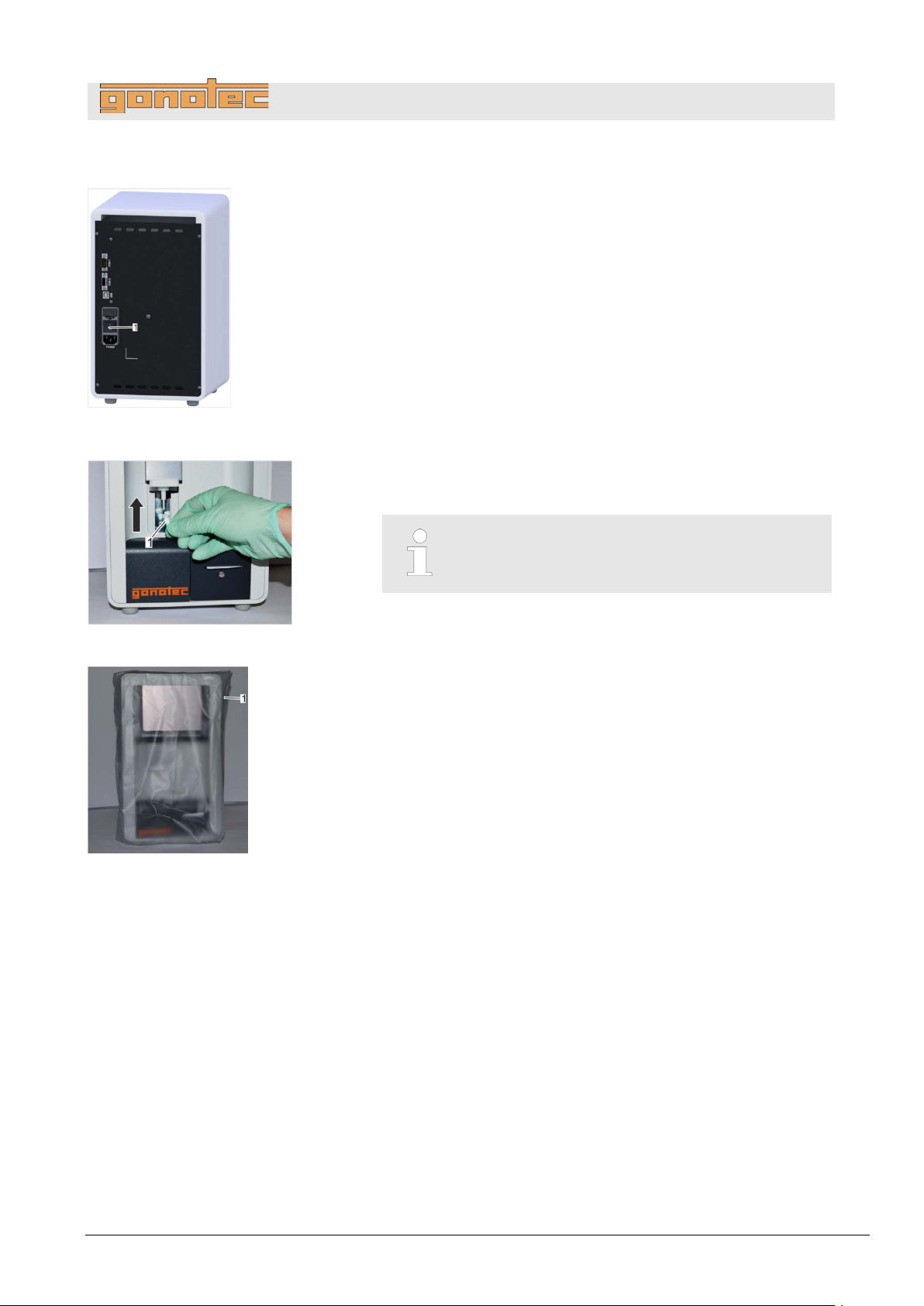
OSMOMAT 3000
basic
// OSMOMAT 3000
Personnel:
Safety gear:
Fig.
1. Power down device using on/off switch on rear side (
and disconnect power plug.
Fig.
2. Position a measurement vessel (
sensor.
Fig.
3. Disinfect device if powered down for an extended period of time.
Wipe device using a wipe moist ened with disinf ec tan t .
4. Pull protective sleeve (
device.
7.6 Power down device
81: Power down device
Operation
User
Disposable lab gloves
Fig. 81/1)
Fig. 82/1) on the temperature
The measurement vessel is securely attached to
the temperature sensor when it clicks into place.
82: Position measurement vessel
83: Device with protective sleeve
Fig. 83/1) included with the del i ver y over
Version 1.22 1/6/2016 71
Page 72
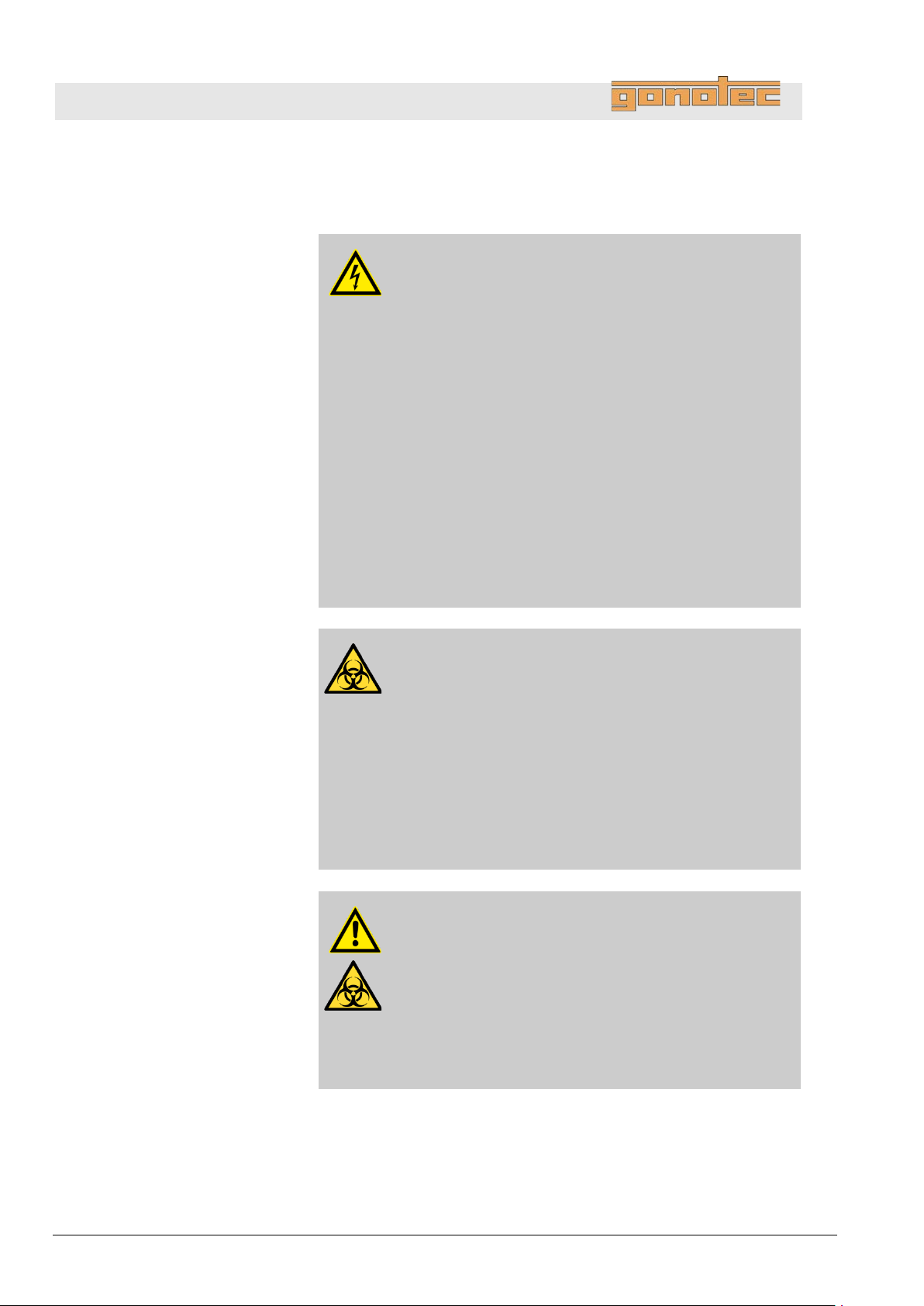
OSMOMAT 3000
basic
// OSMOMAT 3000
Electrical current
Risk of infection
Risk of injury
Troubleshooting
8 Troubleshooting
8.1 Safety notices
DANGER!
Risk of death due to electrical current on device!
Contact with energized parts of the device results in
immediate risk of death due to electric shock. Damage
to the insulation of individual components can cause
risk of death.
- Only have qua lifie d per sonnel perform repair and
maintenance work on the device.
- If the insulation is damaged, immediately switch off
the voltage supply and schedule a repair.
- Always route the power cable so it is not subject to
stress and cannot be bent, pinched, or rolled over
and is not exposed to liquids or heat.
- Ensure easy access to the power socket at all times.
- Keep energized parts away from liquids. Otherwise,
shorts may occur.
WARNING!
Risk of injury due to sample residue and in case of
inadequate hygiene, disinfection, a n d sterilization
procedures!
Exposure to sample residue in non-cleaned, nonsterilized, or non-disinfected components results
in an elevated risk of infection.
- Wear lab gloves during any kind of work.
- Observe all local regulations regarding hygiene,
disinfection, and sterilization.
CAUTION!
Risk of injury from cryst-needle!
When installing and removing the cryst-needle and
the temperature sensor, the tip of the cryst-needle is
exposed. Movement of the cryst-needle can cause
needle puncture injuries.
- Always keep your hands and fingers clear from
the area underneath the cryst-needle.
72 Version 1.22 1/6/2016
Page 73
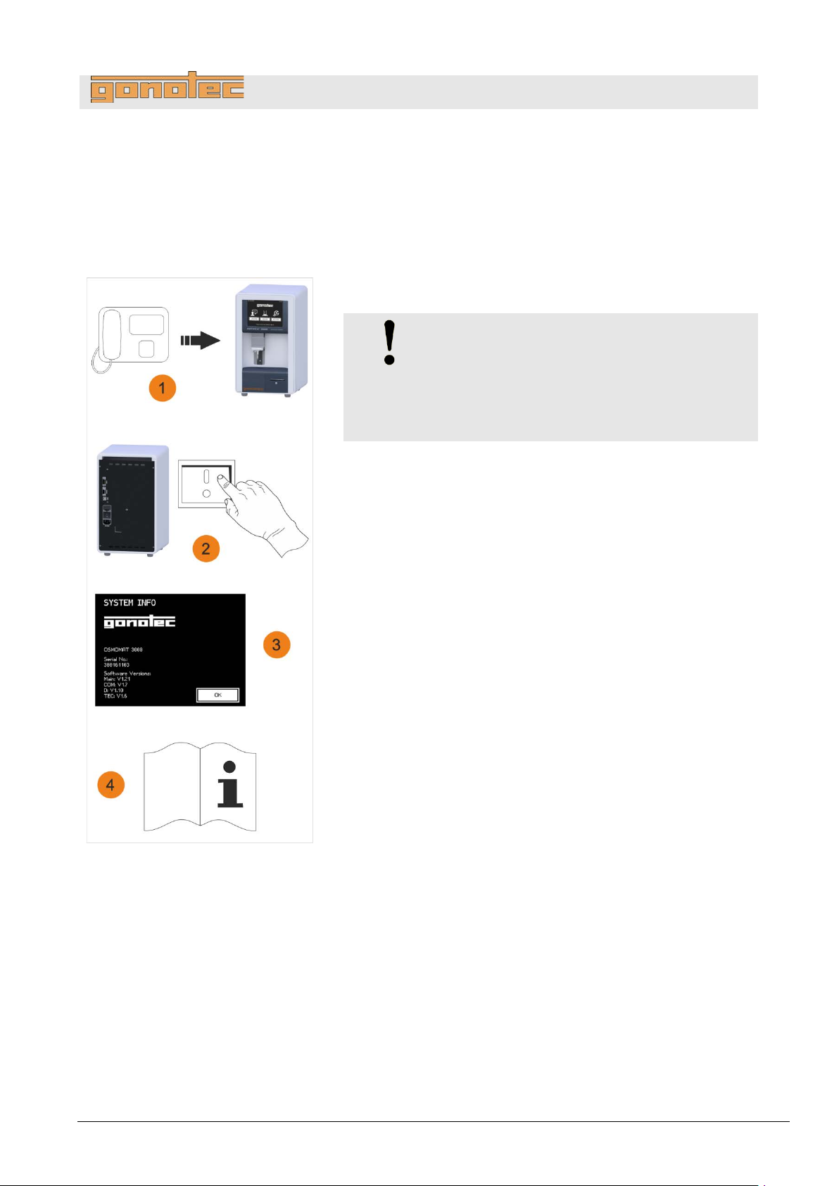
OSMOMAT 3000
basic
// OSMOMAT 3000
In case of errors that cannot be resolved using the error table on
Please be prepared when contacting the manufacturer as follows:
Fig.
1 Use a telephone located close to the device.
2 Power up device.
3 Note down the serial number of the device.
You can find the serial number on the rear of the device or under
Settings
4 Have the device documentation available.
8.2 Notes regarding errors
page 74, contact the manufacturer.
NOTE!
Danger in case of continuous acoustic alarm!
In case of continuous acoustic alarm, the
electronics components of the device can be
damaged.
Power down device again.
Info.
Troubleshooting
Contact info:
Gonotec GmbH
GSG-Hof Reuchlinstr. 10-11
10553 Berlin
Germany
Phone: (030) 7809 588-0
Fax: (030) 7809 588-88
E-mail: [email protected]
Web: http://www.gonotec.com
84: Contact Gonotec
Version 1.22 1/6/2016 73
Page 74

OSMOMAT 3000
basic
// OSMOMAT 3000
Error description
Possible Cause
Remedy
Personnel
Troubleshooting
8.3 Error table
Elevator gets stuck or
makes squeaking
noises when lowered
Lower cooling system
does not cool sample
Mechanical wear
Blockage from foreign
substances
Mechanical wear
Fan is defective or
obstructed
Peltier element is
defective
Errors marked * are shown as an error message on
the touchscreen.
Lubricate the elevator guide using
User
silicone spray ( page 100)
Check openings and remove foreign
User
objects
Clean cooling clamp ( page 90) Service
technician
Check if fan is operational
and replace if necessary
( service manual)
Replace lower cooling system
( service manual)
Motor of cryst-needle
turns without stopping
or
does not turn one full
revolution
No crystallization*
or
Poor ice crystal
formation in upper
cooling system
Light barrier on motor
disk is defective
Light barrier on motor
disk is misaligned
Motor disk misaligned
or loose
Ambient air too dry
Hole above temperature
sensor dirty or blocked
by water droplets
Replace light barrier
( service manual)
Adjust light barrier
Adjust/tighten motor disk
Clean cooling nipple using a fiberglass
pin ( page 88)
Wait at least 2 minutes after switching
on device before starting
measurement.
If the humidity is very low (for example,
in heated or air-conditioned rooms),
open the cover of the upper cooling
system until you can see ice crystals
forming.
Blow out hole using blow-out device
Service
technician
User
74 Version 1.22 1/6/2016
Cooling nipple dirty
Clean cooling nipple using a fiberglass
pin ( page 88).
Remove any droplets from opening
using blow-out device.
Page 75

OSMOMAT 3000
basic
// OSMOMAT 3000
Error description
Possible Cause
Remedy
Personnel
No crystallization *
or
Poor ice crystal
formation in upper
cooling system
Peltier element
defective
Cable connection
between cooling system
and PCB defective
Cryst-needle too long
or too short
Cryst-needle not
deburred
Cryst-needle bent
Cryst-needle does
not move
Cryst-needle disengaged from motor
or stuck
Troubleshooting
Replace upper cooling system
( service manual)
Adjust cryst-needle to correct length
( page 80)
Debur cryst-needle using fine
sandpaper
Manually bend cryst-needle so that
it is vertical, replace if necessary
( page 79)
Verify free movement of cryst-needle
( page 81)
Service
technician
Measurement
procedure takes
longer than usual
Spontaneous
crystallization*
Error in rotation of
motor disk (cryst-needle
drive)
Fan is defective or
obstructed
Peltier element is
defective
Sample not prepared
correctly
Temperature sensor not
aligned correctly
Align cryst-needle ( page 79) Service
technician
Correct length of cryst-needle
( page 80)
Check if light barrier is located
properly and replace if necessary
( service manual)
Tighten motor disk
Check if fan is operational and
remove any foreign objects
Replace fan ( service manual)
Replace lower cooling system
( service manual)
Use sample according to
performance data of device
( page 15)
Align temperature sensor
( page 86)
Service
technician
User
Service
technician
Elevator moved up by
user
Leave the elevator in the lowered
position during the measurement
procedure
Version 1.22 1/6/2016 75
User
Page 76

OSMOMAT 3000
basic
// OSMOMAT 3000
Error description
Possible Cause
Remedy
Personnel
Troubleshooting
Incorrect
measurement results
Lower cooling system
not aligned correctly
Incorrect measurement
vessel used
Measurement vessel
re-used
Measurement vessel
not positioned correctly
Temperature sensor
defective
Align lower cooling system
( service manual)
Only use measurement vessels
of the correct type supplied by
Gonotec GmbH
Use measurement vessels only
once.
Position measurement vessel with
cover pointing forward
When the measurement vessel
clicks into place, it is securely
positioned on the temperature
sensor.
Replace temperature sensor
( page 82)
Service
technician
User
Service
technician
Temperature sensor
not centered
Negative
measurement values
Measurement vessel
fits too loosely on
temperature sensor
Fan malfunction Fan is obstructed
Zero point calibration
performed using impure
water
Incorrect measurement
vessel used
Measurement vessel
re-used
Measurement vessel
not positioned correctly
Temperature sensor
damaged
Align temperature sensor
( page 86)
Repeat calibration ( page 65)
Only use measurement vessels
supplied by Gonotec GmbH
Position measurement vessel with
cover facing forward
When the measurement vessel
clicks into place, it is securely
positioned on the temperature
sensor.
Replace temperature sensor
( page 82)
Check if fan is operational and
remove any foreign objects
User
User
User
Service
technician
Service
technician
Fan makes loud
noise
76 Version 1.22 1/6/2016
Fan is defective
Fan is obstructed
Replace fan ( service manual)
Check if fan is operational and
remove any foreign objects
Page 77

OSMOMAT 3000
basic
// OSMOMAT 3000
Error description
Possible Cause
Remedy
Personnel
Error message:
Needle stuck*
Microfuses trip when
powering up device
Device cannot be
powered up
Needle bar disengaged
from motor or stuck
Motor slider misaligned
Device voltage does
not match power grid
voltage
Power supply not
correctly plugged into
power socket
Power socket is dead
Power cable is
damaged
Troubleshooting
Verify free movement of cryst-needle
( page 81)
see also: Motor of cryst-needle turns
without stopping or does not turn
one full revolution.
Check device voltage setting
Connect power supply to a power
socket
Connect device to a live power
socket
Replace power cable
Service
technician
Service
technician
Service
technician
Fuses are burned out
Printer does not print Paper roll is used up
Ribbon is empty
Measurement
procedure aborted
User moved elevator up
during measurement
Replace fuses ( page 89)
Replace paper roll ( page 90)
User
Replace ribbon ( page 92)
Repeat measurement User
by user*
Incorrect PIN entry* Incorrect PIN entry Re-enter PIN or cancel operation
Lab
supervisor
Attempt to change lab
supervisor password
failed*
Repeat password entry
does not match first
entry
Change password again
Lab
supervisor
Unexpected errors* Internal system errors Contact Gonotec GmbH User
Version 1.22 1/6/2016 77
Page 78
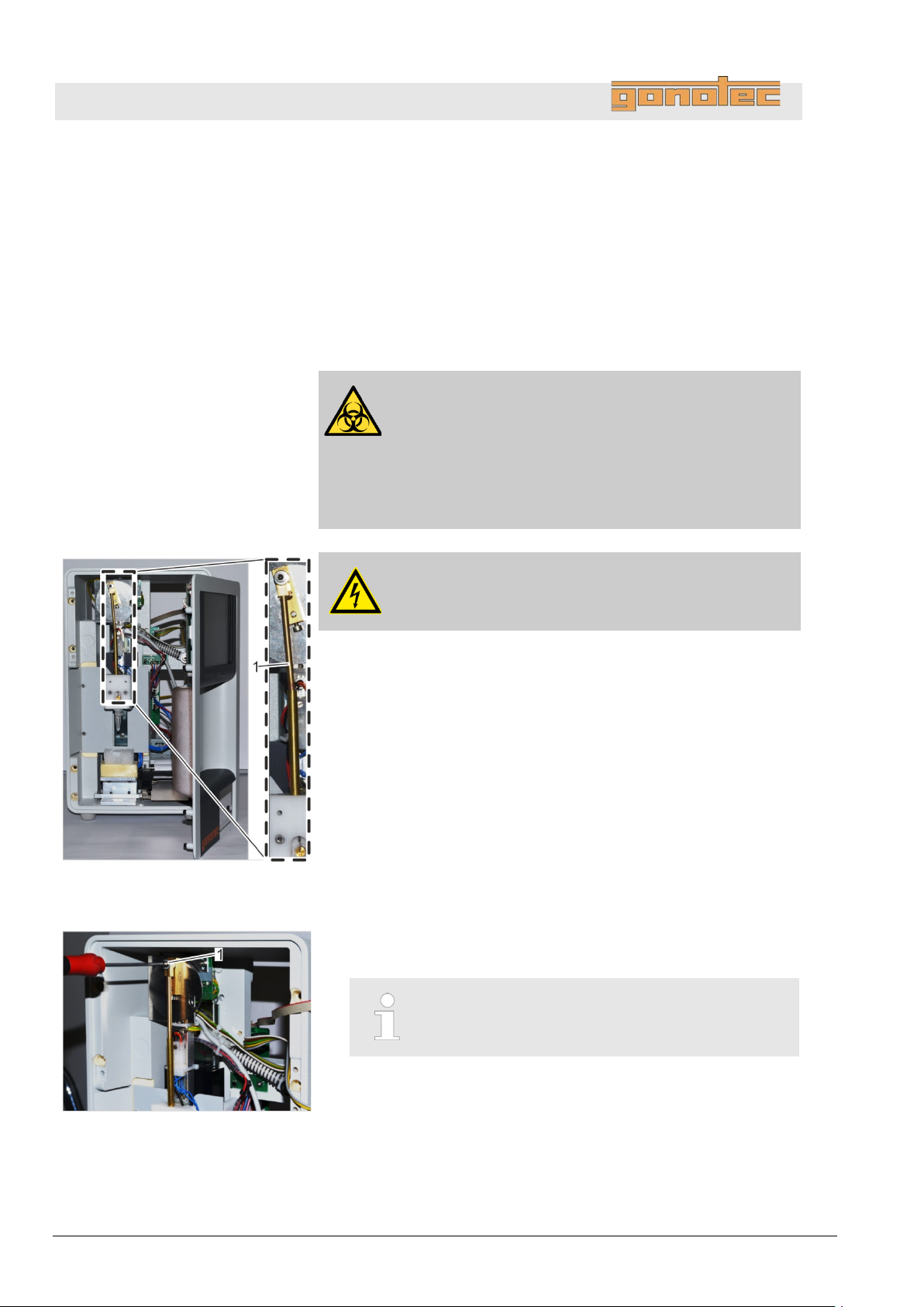
OSMOMAT 3000
basic
// OSMOMAT 3000
Personnel:
Safety gear:
Materials:
Fig.
1 Cryst-needle
1. Power down device using on/off switch on rear side and
disconnect power plug.
2. Remove device front panel (
Fig.
3. Remove mounting screw (
cryst
Troubleshooting
8.4 Resolve errors
8.4.1 Replace cryst-needle
Service technician
Disposable lab gloves
Allen key SW 2.5
Precision key file
Wire cutter
WARNING!
Risk of infection from sample residue!
The cryst-needle is immersed into the sample during
measurements. Contact with the cryst-needle increases
the risk of infection.
- Wear lab gloves during any kind of work.
DANGER!
Risk of death due to electrical current!
on page 95).
85: Position of cryst-needle and details
Fig. 86/1) of cryst-needle while holding
-needle in place.
The mounting screw has a coating of locking paint.
86: Remove mounting screw
78 Version 1.22 1/6/2016
Page 79
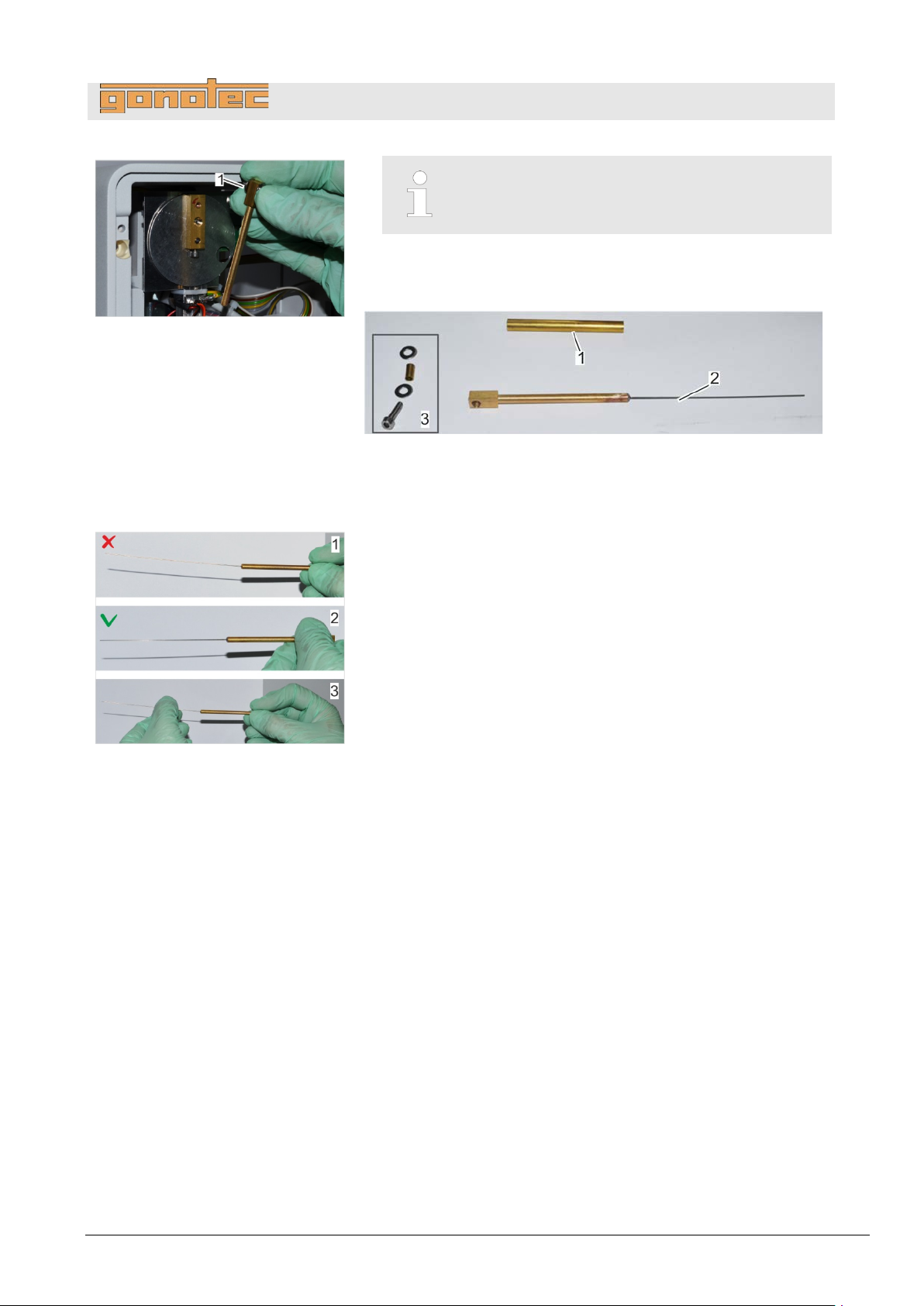
OSMOMAT 3000
basic
// OSMOMAT 3000
Fig.
4
Loose washer between cryst-needle and
Remove cryst
of
Fig.
5. Remove guide tube (
cryst
Fig.
6. Make sure that the new cryst
(
1 -
Incorrect orientation
2 -
Correct orientation
If necessary, bend cryst
7
Shorten cryst
Proceed as follows.
87: Remove cryst-needle
Troubleshooting
.
motor disk!
-needle from motor disk. Hold washer (Fig. 87/1)
mounting screw in place.
88: Cryst-needle components
Fig. 88/1) and fasteners (Fig. 88/3) of
-needle (Fig. 88/2).
-needle is as straight as possible
Fig. 89/1+2).
89: Straighten cryst-needle
-needle so it is straight (Fig. 89/3).
.
-needle to correct length.
Version 1.22 1/6/2016 79
Page 80
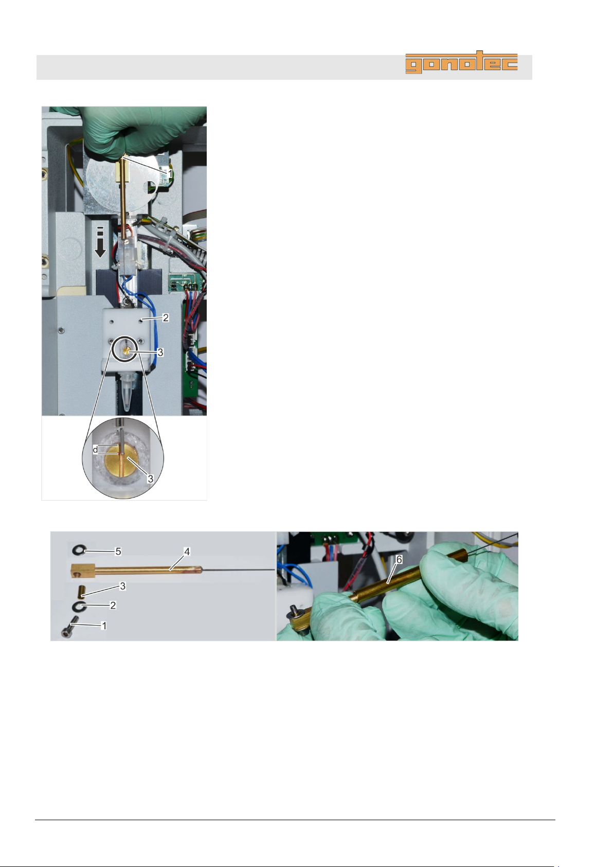
OSMOMAT 3000
basic
// OSMOMAT 3000
Fig.
8
Align
The set screw of the motor swipe points down.
9. Move cryst
(
10
Bolt new needle to motor disk.
11
Align cryst
The needle end should be located approx. 2mm below the
lower
12. If the needle is too long, use a permanent marker to mark the
correct length and remove the needle bar again.
13. Trim excess wire using side cutters and debur needle tip using
precision key file.
Fig.
1 Mounting screw
2 Washer
3 Fastening tube
4 Cryst-needle
5 Washer
6 Guide tube
Troubleshooting
.
motor swipe vertically with upper dead center (Fig. 90/1).
-needle through guide tube in upper cooling system
Fig. 90/2) onto cooling nipple (Fig. 90/3).
.
.
-needle with motor swipe and cooling nipple.
edge of the cooling nipple (d=2mm). (Fig. 90/3).
90: Adjust length of cryst-needle
91: Install cryst-needle
80 Version 1.22 1/6/2016
Page 81
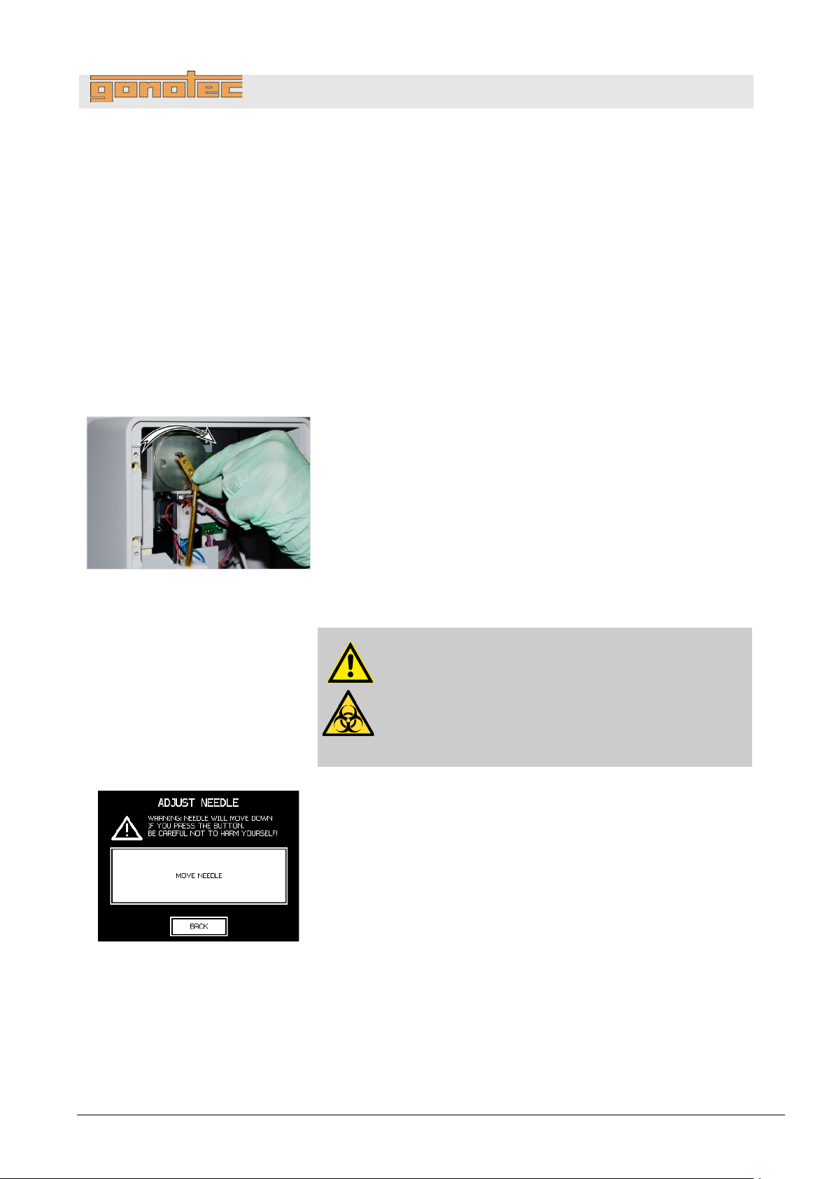
OSMOMAT 3000
basic
// OSMOMAT 3000
14
Fit cryst
1 -
Push washer (
mounting screw (
2 -
Push mounting screw with washer and fastening screw
through head of cryst
3 -
Secure washer (
4 -
Push guide tube (
15. Secure cryst
(
Check free movement
of cryst-needle
Fig.
of
16. Turn motor disk with attached cryst
cryst
If needle gets jammed,
(
17. Install device front panel (
18
Power up device on rear side using on/off switch.
19
Verify free movement of cryst
Open the menu for adjusting the
Lab
Fig.
20. Tap
The needle turns by one revolution.
Tap
Troubleshooting
.
-needle to motor disk. Assemble fasteners as follows:
Fig. 91/2) and fastening tube (Fig. 91/3) onto
Fig. 91/1).
-needle (Fig. 91/4).
Fig. 91/5) to mounting screw.
Fig. 91/6) onto cryst-needle.
-needle to motor disk (Fig. 86) using mounting screw
Fig. 91/1).
-needle clockwise to check
-needle for free movement.
detach needle and check if it is bent.
Fig. 89).
92: Check free movement
cryst-needle
on page 99).
.
.
-needle automatically.
cryst-needle (Start menu
Options Maintenance Adjust Needle).
CAUTION!
Risk of injury from cryst-needle!
The tip of the cryst-needle is exposed. Movement of
the cryst-needle can cause needle puncture injuries.
- A lways keep your hands and fingers clear from
the area underneath the cryst-needle.
Move Needle to test the free movement.
Back to exit the menu.
93: Move needle
Version 1.22 1/6/2016 81
Page 82
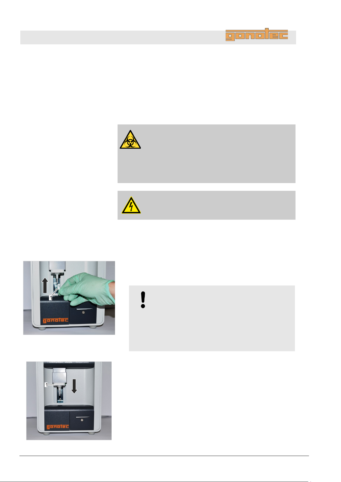
OSMOMAT 3000
basic
// OSMOMAT 3000
Personnel:
Safety gear:
Materials:
1. Power down device using on/off switch on rear side and
disconnect power plug.
Remove elevator cover
Fig.
2. To protect thermistor, cover
a
vessel
Fig.
3
Move elevator down using handle (
Troubleshooting
8.4.2 Replace the temperature sensor
Service technician
Disposable lab gloves
Allen key SW 2
Adjustment tool
Tweezers
WARNING!
Risk of injury in case of inadequate hygiene ,
disinfection, and sterilization procedures!
Contact with the temperature sensor and cryst-needle
increases the risk of infection due to sample residue.
- Wear lab gloves during any kind of work.
DANGER!
Risk of death due to electrical current!
94: Position measurement vessel
temperature sensor with
measurement vessel. The cover of the measurement
must point forward.
NOTE!
Risk of thermistor damage due to loose positi on
of measurement vessel!
Resistance is felt when sliding on measurement
vessel.
When the measurement vessel clicks into place, it
is securely positioned on the temperature sensor.
.
Fig. 95/1).
95: Move elevator down
82 Version 1.22 1/6/2016
Page 83
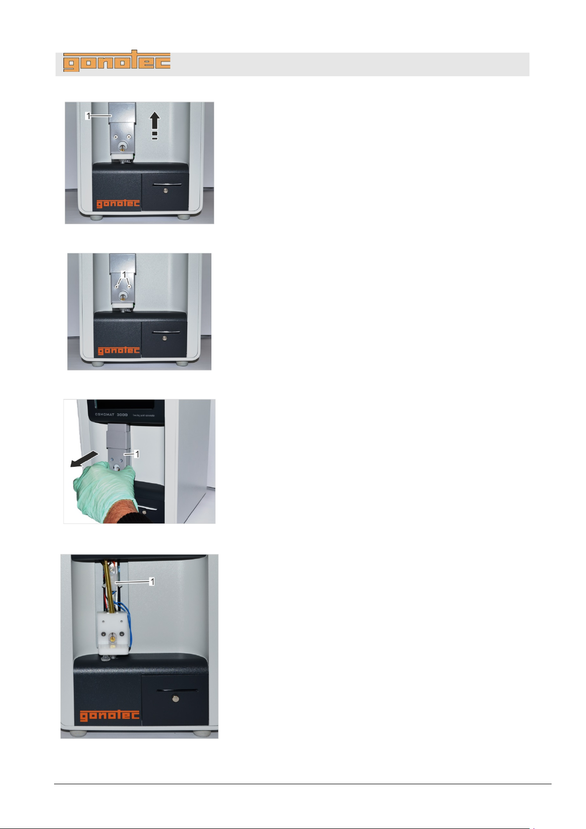
OSMOMAT 3000
basic
// OSMOMAT 3000
Fig.
4
Move elevator cover (
Fig.
5. Remove the 2 mounting screws (
(SW
Fig.
6
Remove the complete elevator cover (
Fig.
7
Pull connector of temperature sensor (
96: Move elevator cover up
.
Fig. 96/1) up.
Troubleshooting
Fig. 97/1) using Allen k e y
2).
97: Remove mounting screws
.
Fig. 98/1).
98: Remove elevator cover
.
Fig. 99/1).
99: Pull connector
Version 1.22 1/6/2016 83
Page 84
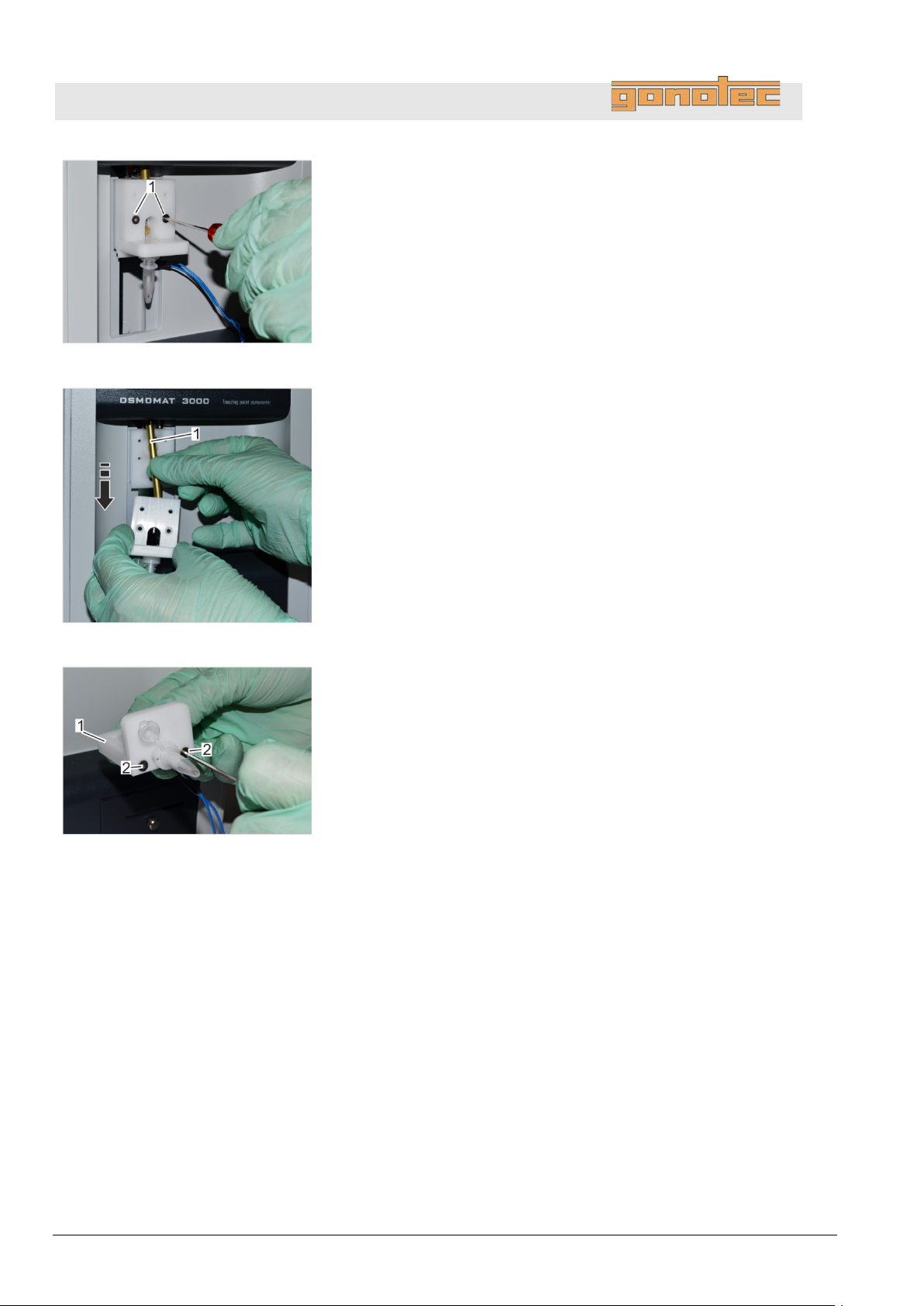
OSMOMAT 3000
basic
// OSMOMAT 3000
Fig.
8. Move elevator up and remove the 2
/1)
using Allen key (SW
Fig.
9. Remove temperature sensor with mounting plate toward the front
(
in
10
If necessary, clean cooling nipple.
Fig.
11. Use Allen key (SW 2) (
from mounting plate (
Troubleshooting
100: Remove mounting screws
mounting screws (Fig. 100
2).
Fig. 101) while holding guide tube of c r yst-needle (Fig. 101/1)
place.
.
101: Remove temperature sensor
102: Remove mounting plate
Fig. 102/2) to remove temperature sensor
Fig. 102/1).
84 Version 1.22 1/6/2016
Page 85
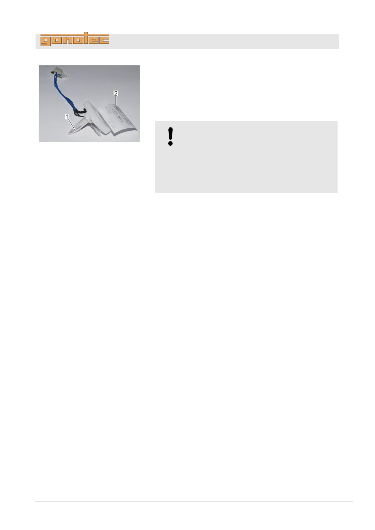
OSMOMAT 3000
basic
// OSMOMAT 3000
Fig.
data sheet
12
Fit new temperature sensor to mounting plate (
Keep the data sheet affixed to the temperature sensor
(
T
a
measurement vessel must point forward.
13. Push guide tube onto cryst
stainless steel tube of mounting plate (
103: New temperature sensor with
.
Fig. 103/2) in the vicinity of the device.
o protect thermistor, cover temperature s ensor with
measurement vessel (Fig. 103/1). The cover of the
NOTE!
Risk of thermistor damage due to loose positi on
of measurement vessel!
Resistance is felt when sliding on measurement
vessel.
When the measurement vessel clicks into place, it
is securely positioned on the temperature sensor.
-needle and pass needle through
Fig. 101).
Troubleshooting
Fig. 102).
Version 1.22 1/6/2016 85
Page 86
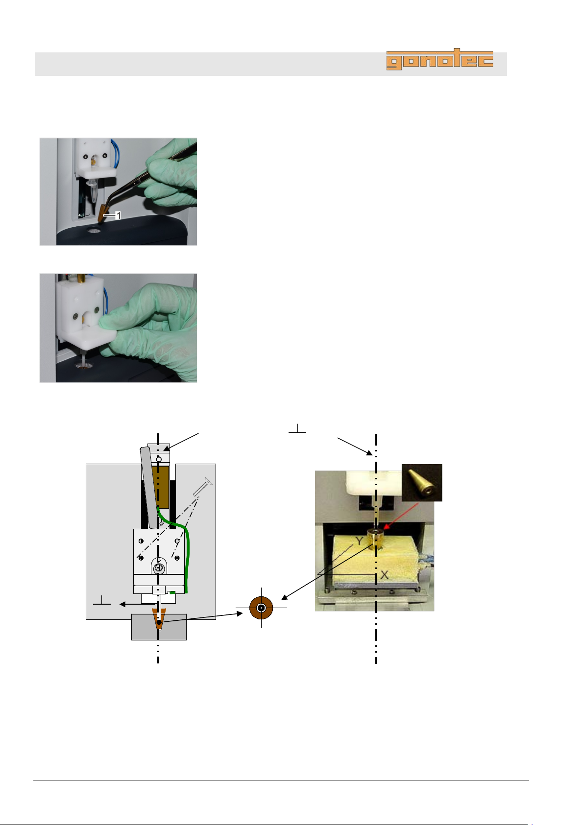
OSMOMAT 3000
basic
// OSMOMAT 3000
Align the temperature sensor
14
Tighten the 2 mounting screws only lightly.
The temperature sensor must be aligned using
Fig.
15. Install adjustment tool (
system using tweezers.
16
Remove measurement vessel from temperature sensor.
Fig.
17
Align temperature sensor (
Push temperature sensor
18. Position temperature sensor on XY plane so that thermistor is
perpendicular to center of
Fig.
19. Tighten the 2 mounting screws on the aligned temperature
sensor.
Adjustment
lower cooling system
Thermistor Z axis ( )
Mounting screws
Troubleshooting
104: Install adjustment tool
.
the adjustment tool.
Fig. 104/1) in opening of lower c ooling
.
.
Fig. 105). Proceed as follows:
just beyond adjustment tool.
hole of adjustment tool (Fig. 106 and
107).
105: Align the temperature sensor
Fig. 106: Temperature sensor Z axis
tool
Fig. 107: Temperature sensor XY plane
86 Version 1.22 1/6/2016
Page 87
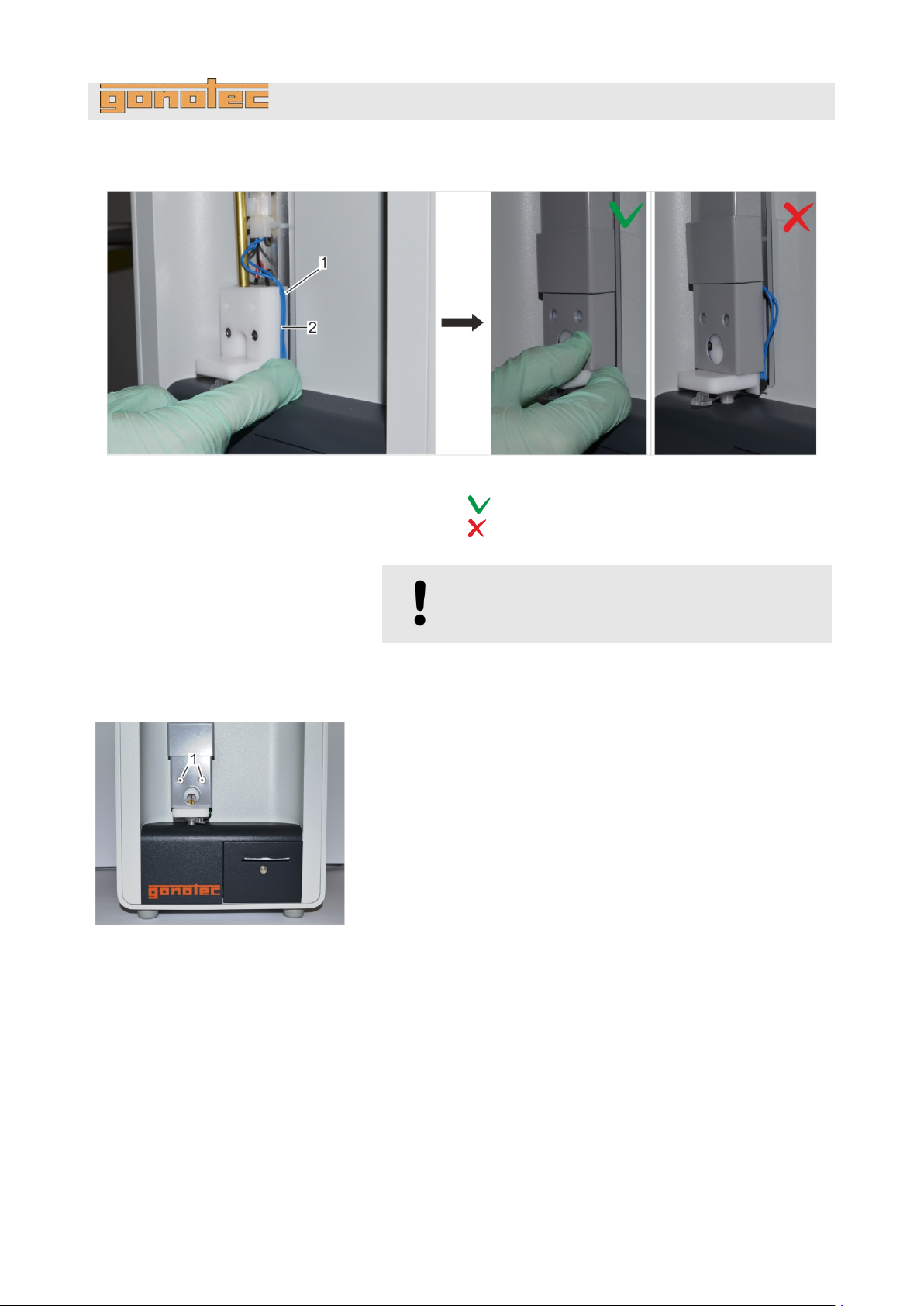
OSMOMAT 3000
basic
// OSMOMAT 3000
Install elevator cover
Fig.
1 Cable
2 Cable guide on temperature sensor
Correct cable routing
Incorrect cable routing
20
Place cable (
(
Fig.
21. Bolt elevator cover to elevator using the 2 mounting screws
(
The tem
108: Elevator cover with correct cable routing
Troubleshooting
109: Tighten mounting screws
.
NOTE!
Risk of cable break!
Fig. 108/1) on temperature sensor in cable guide
Fig. 108/2) and install elevator cover on device.
Fig. 109/1).
perature sensor is now installed.
Version 1.22 1/6/2016 87
Page 88
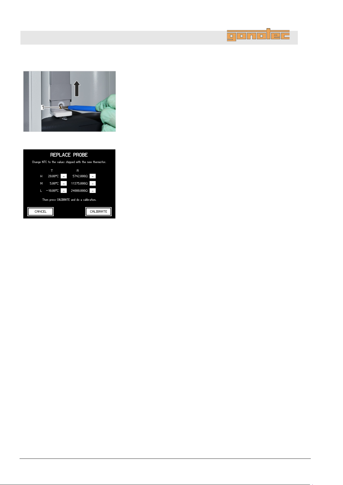
OSMOMAT 3000
basic
// OSMOMAT 3000
Clean cooling nipple
Fig.
22. Clean cooling nipple (
purpose, move elevator cover up.
23
Power up device on rear side using on/off switch.
24
Calibrate the
For this purpose, open the Replace Probe menu (
Lab Options
Fig.
25. Copy the values from the included
tap
The system starts the device calibration.
Perform a 3
Use
300
Troubleshooting
110: Clean cooling nipple
Fig. 110/1) using a fiberglass pin. For this
.
.
new temperature sensor.
Start menu
Maintenance Replace Probe).
data sheet to the fields and
Calibrate.
-point calibration on the device ( page 65).
distilled water and the two calibra tio n standar ds with
and 850 mOsm/kg.
111: Calibrate temperature sensor
88 Version 1.22 1/6/2016
Page 89
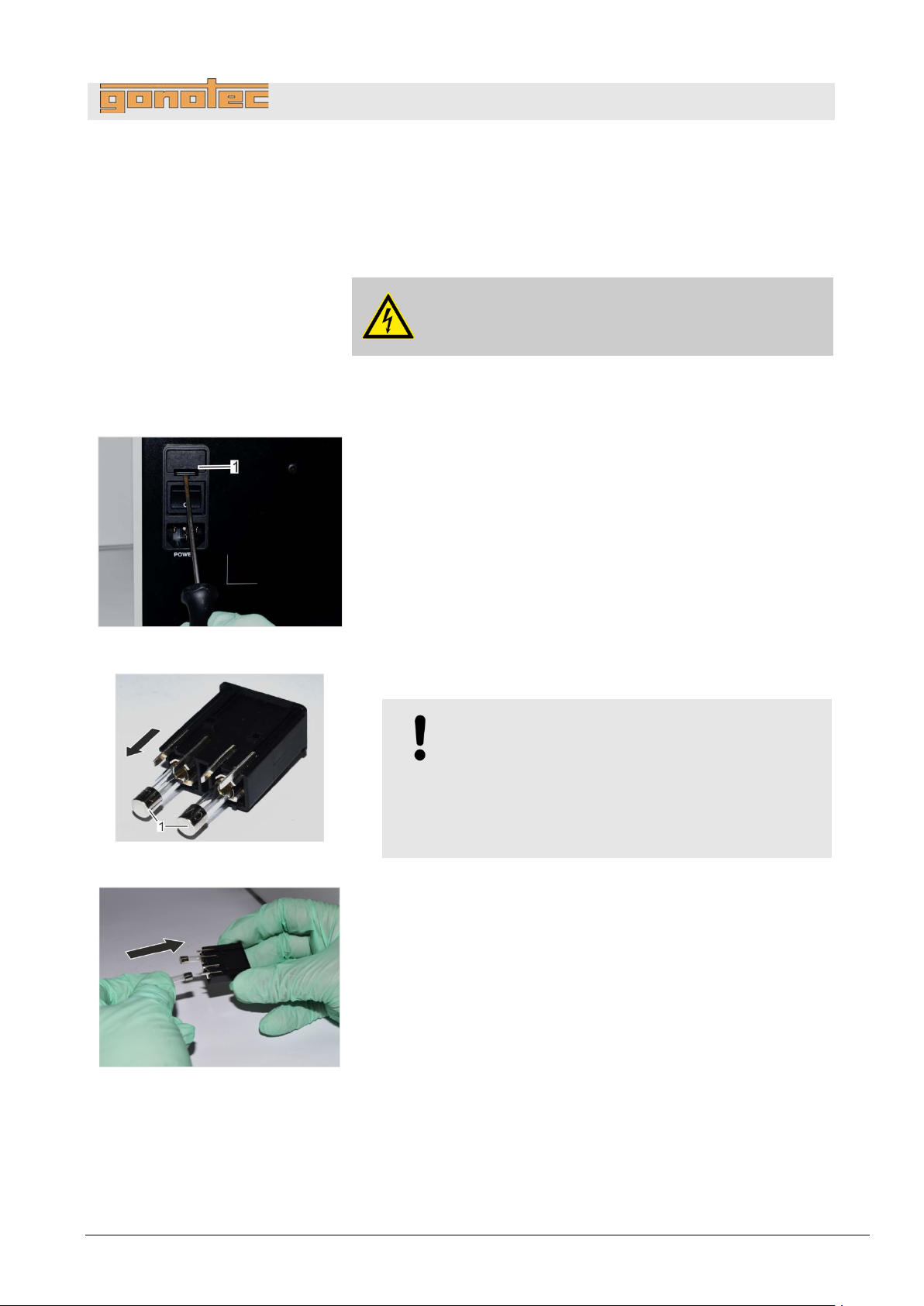
OSMOMAT 3000
basic
// OSMOMAT 3000
Safety gear:
Materials:
1. Power down device using on/off switch on rear side and
disconnect power plug.
Fig.
2
Open cover (
3
Remove microfuse attachment.
Fig.
4
Remove microfuses (
Fig.
5. Push the microfuses included with the delivery into
the
8.4.3 Replace microfuses
Troubleshooting
Disposable lab gloves
Flat blade screwdriver
Microfuses (slow-blow 1.6A)
DANGER!
Risk of death due to electrical current!
.
.
Fig. 112/1) using a flat blade screwdriver.
112: Open microfuse cover
113: Remove microfus es
114: Install microfuses
.
Fig. 113/1) from attachment.
NOTE!
Risk of property damage!
The unit has two-phase protection. Use onl y
the following fuses:
Slow-blow HBC fuses (1.6A) with a switching
capacity of 1500A
attachment (Fig. 114).
Version 1.22 1/6/2016 89
Page 90
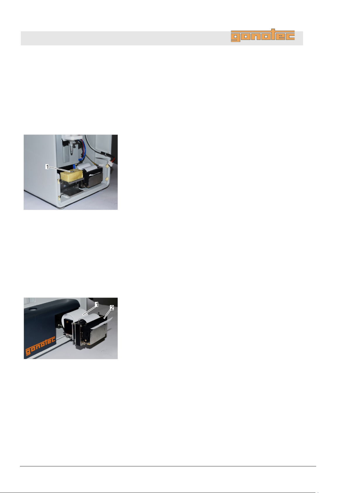
OSMOMAT 3000
basic
// OSMOMAT 3000
Personnel:
Safety gear:
Materials:
1
Power down device on rear side using on/off switch.
2. Remove device front panel (
Fig.
3. Clean cooling clamp (
using
4. Install device front panel (
Personnel:
Safety gear:
Materials:
Fig.
1 Paper roll
2 Ribbon
1
Power down device on rear side using on/off switch.
Troubleshooting
8.4.4 Clean cooling clamp
115: Clean cooling clamp
Service technician
Disposable lab gloves
Fine sandpaper
.
on page 95).
Fig. 115/1) on lower cooling system
sandpaper.
on page 99).
8.4.5 Replace printer paper (Option D only)
(does not apply to OSMOMAT 3000
116: Printer (pulled out)
basic)
.
User
Disposable lab gloves
1 Paper roll
90 Version 1.22 1/6/2016
Page 91
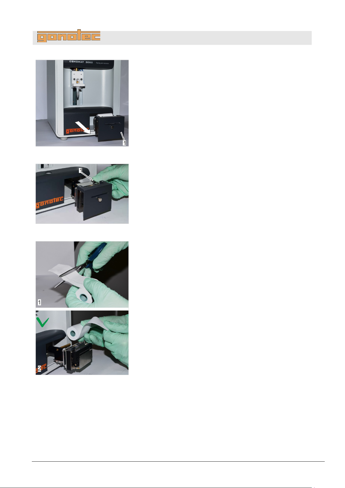
OSMOMAT 3000
basic
// OSMOMAT 3000
Fig.
2
Pull out
Fig.
3
Turn knurled screw (
4
Remove empty paper roll from holder and dispose.
Fig.
5. Cut off
onto
Pay attention to correct feed direction of paper (
6. Position knurled screw (
clockwise.
7
Power up device on rear side using on/off switch.
117: Pull out printer
.
printer (Fig. 117/1).
Troubleshooting
.
.
Fig. 118/1) counter-clockwise.
118: Turn knurled screw
beginning of new paper roll (Fig. 119/1) and push
holder.
Fig. 119/2).
Fig. 118/1) and tighten by turning
.
119: Install paper roll
Version 1.22 1/6/2016 91
Page 92
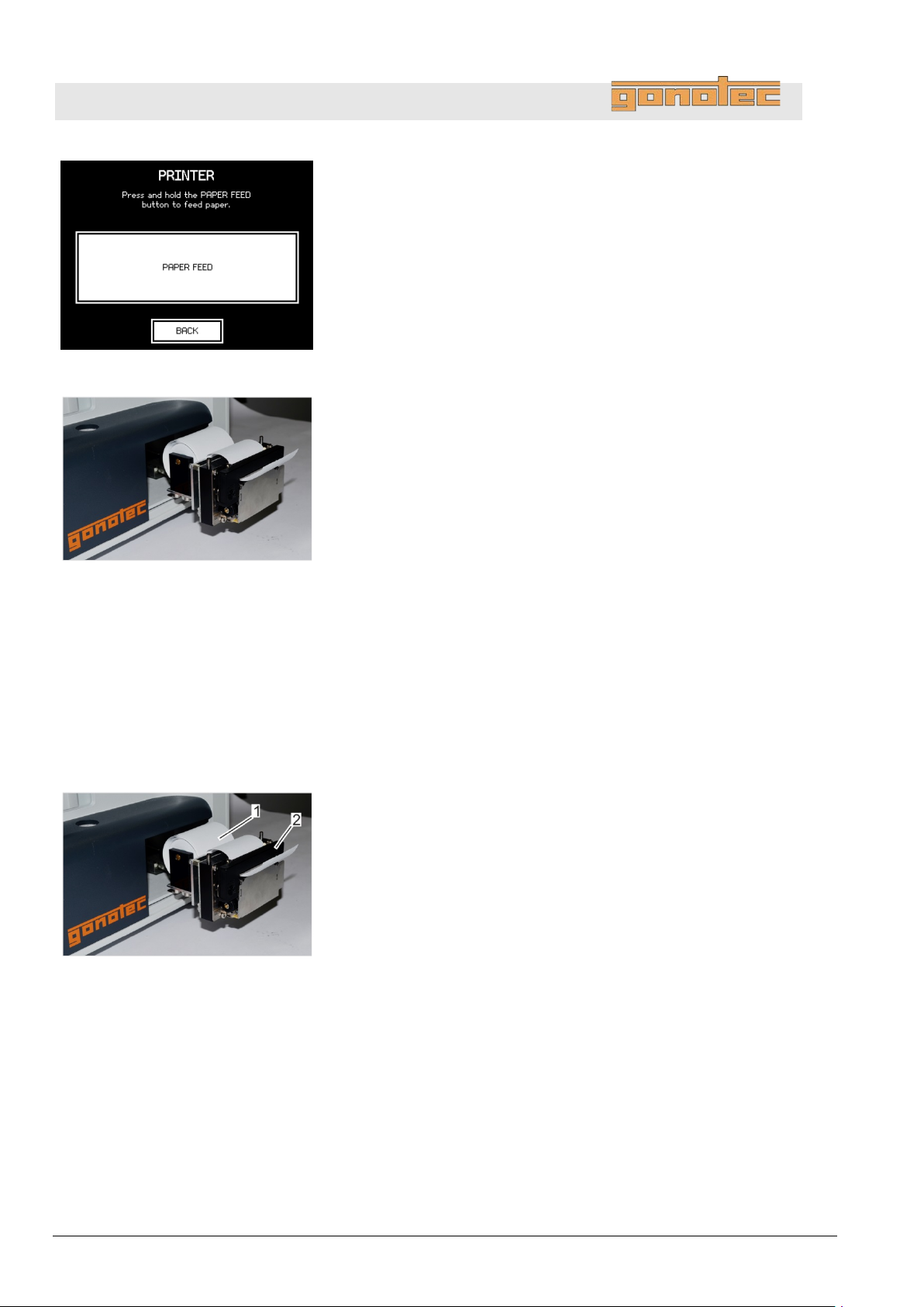
OSMOMAT 3000
basic
// OSMOMAT 3000
Fig.
8. On the Start menu, select
Tap
Fig.
The paper feed of the printer is activated briefly. (
Tap
9
Replace printer cover and push printer into casing.
Personnel:
Safety gear:
Materials:
Fig.
1 Paper roll
2 Ribbon
1
Power down device on rear side using on/off switch.
Troubleshooting
120: Activate paper feed
121: Paper feed
Settings Printer.
Paper Feed.
Fig. 121).
Back to exit the menu.
.
8.4.6 Replace printer ribbon (Option D only)
(does not apply to OSMOMAT 3000
122: Printer (pulled out)
basic)
.
User
Disposable lab gloves
1 Ribbon
92 Version 1.22 1/6/2016
Page 93
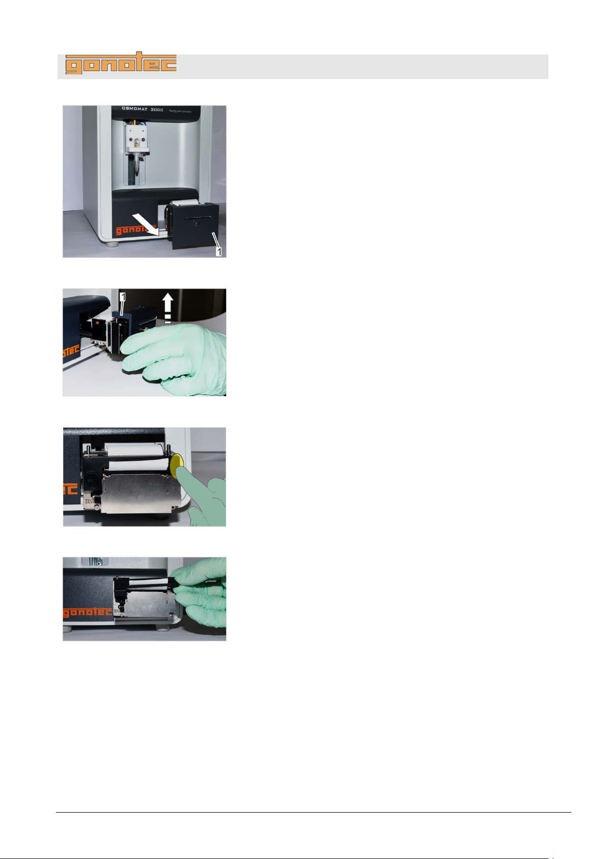
OSMOMAT 3000
basic
// OSMOMAT 3000
Fig.
2
Pull out printer (
Fig.
3
Remove printer cover (
Fig.
4
Push on Push marking on front side of ribbon (
The ribbon is released.
5
Remove the released ribbon.
Fig.
6
Feed printer paper
7
Press ribbon onto device.
The ribbon snaps into place.
8
Tighten ribbon by
9
Replace printer cover and push printer into casing.
123: Pull out printer
.
Fig. 123/1).
Troubleshooting
.
Fig. 124/1).
124: Remove printer cover
125: Push out ribbon
126: Feed printer paper
.
.
Fig. 125).
.
.
.
through ribbon (Fig. 126).
turning knob clockwise.
.
Version 1.22 1/6/2016 93
Page 94
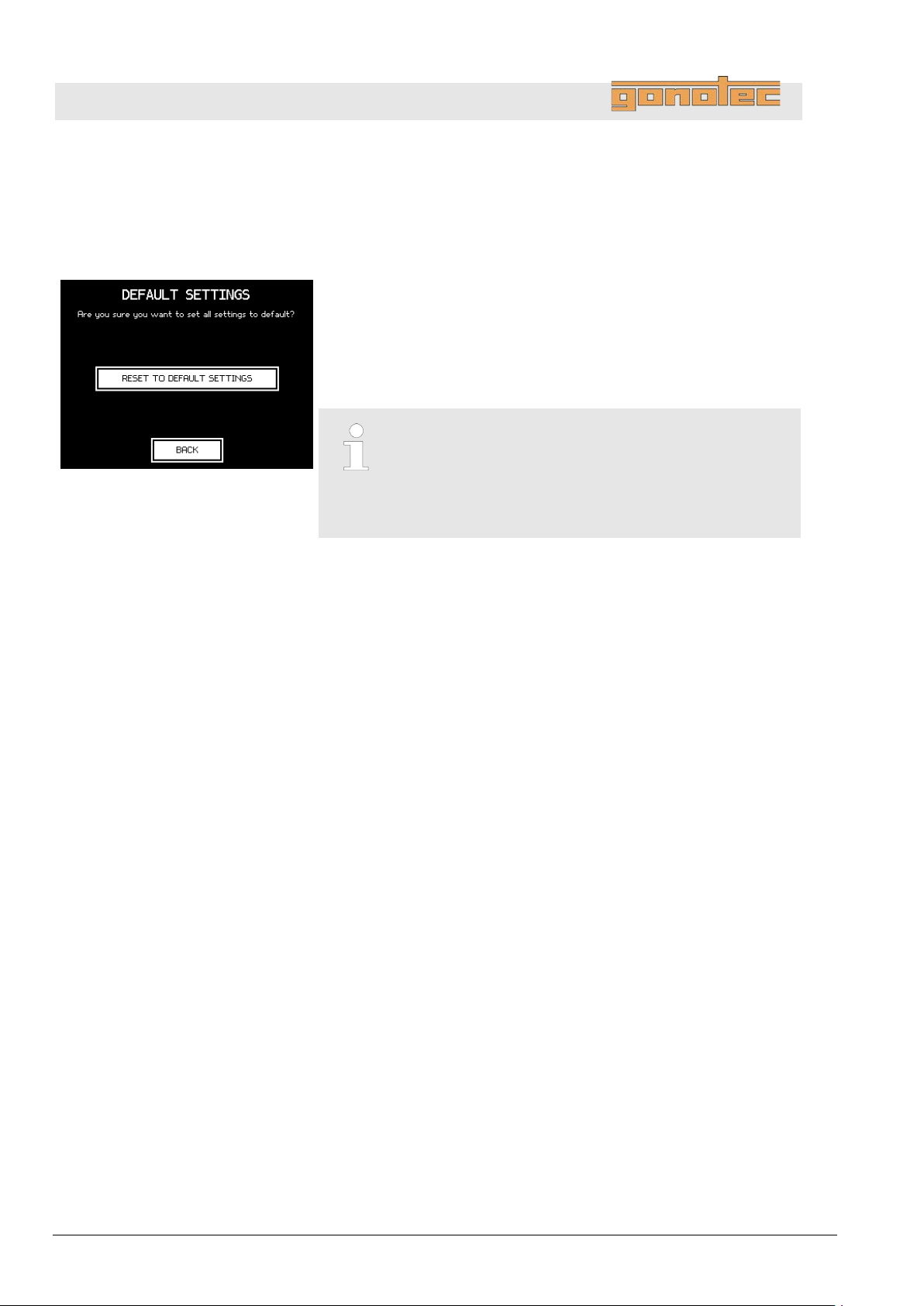
OSMOMAT 3000
basic
// OSMOMAT 3000
If the device no longer functions properly due to incorrect settings,
you
default settings.
To do this, proceed as follows:
Fig.
1
From the Start menu, select
Maintenance
2. Tap
3. Configure the user preferences
Troubleshooting
8.4.7 Reset device to default settings
can undo all the modified user settings and reset device to the
.
chapter 7.2 User Preferences
127: Reset to Default Settings
Settings Lab Options
Default Settings.
Reset to Default Settings (Fig. 127)
.
Resetting the device will also purge all ex istin g
calibration data.
Before performing any measurements on the device
following the reset, recalibration is m andator y.
Chapter 7.5 “Calibrate device” on page 65
94 Version 1.22 1/6/2016
Page 95
OSMOMAT 3000
basic
// OSMOMAT 3000
Electrical current
Risk of infection
9 Servicing
9.1 Safety notices
Servicing
DANGER!
Risk of death due to electrical current on device!
Contact with energized parts of the device results in
immediate risk of death due to electric shock. Damage
to the insulation of individual components can cause
risk of death.
- Only have qualified personnel perform repair and
maintenance work on the device.
- If the insulation is damaged, immediately switch off
the voltage supply and schedule a repair.
- Always route the power cable so it is not subject to
stress and cannot be bent, pinched, or rolled over
and is not exposed to liquids or heat.
- Ensure easy access to the power socket at all times.
- Keep energized parts away from liquids. Otherwise,
shorts may occur.
WARNING!
Risk of infection due to sample residue and in case
of inadequate hygiene, disinfection, and sterilization
procedures!
Exposure to sample residue in non-cleaned, nonsterilized, or non-disinfected components results
in an elevated risk of infection.
- Wear lab gloves during any kind of work.
- Observe all local regulations regarding hygiene,
disinfection, and sterilization.
We recommend using detergents such as Mikrozid®
AF Liquid, Bac il lo l® plus 3%, or Korsolex® plus 4%
commonly found in clinical-chemical labs to clean
and decontaminate the device.
Version 1.22 1/6/2016 95
Page 96
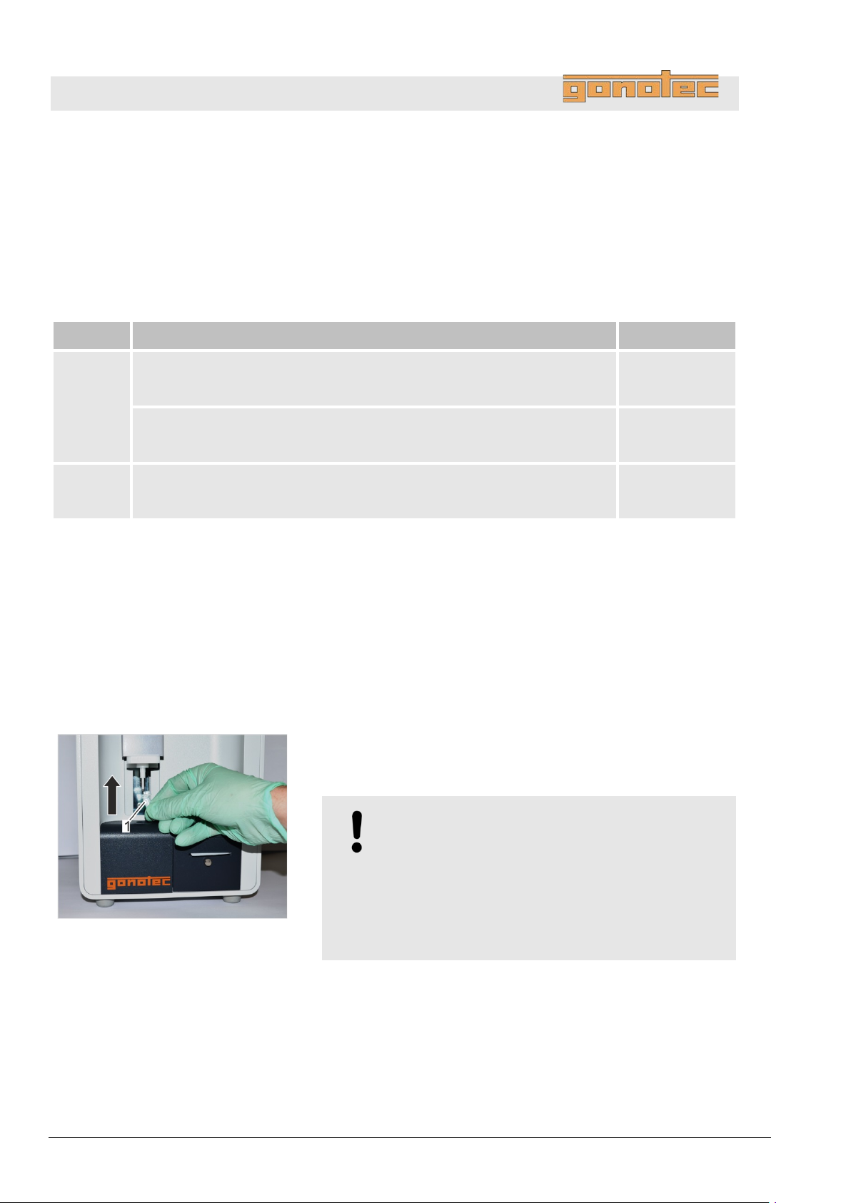
OSMOMAT 3000
basic
// OSMOMAT 3000
The following sections describe the service activities required to
ensure device operation under optimum, error
If regular checks show excess wear, shorten the required service
intervals based on
regarding service activities and intervals, contact the manufacturer
(for
Interval
Service activity
Personnel
Remove device front panel
Personnel:
Safety gear:
Materials:
1
Power down device on rear side using on/off switch.
Fig.
2. To protect thermistor, cover temperature sensor
a
measurement vessel must point forward.
Servicing
9.2 Service table
actual signs of wear. If you have questions
monthly Check elevator support for ease of movement and lubricate if necessary
chapter 9.4 "Preliminary steps" on page 96
Perform visual inspection of device
chapter 9.5 "Perform visual inspection of device" on page 102
Check reproducibility of measurements
chapter 9.6 "Check reproducibility of measurements" on page 103
contact information, see page 2).
-free conditions.
User
User
Lab supervisor
9.3 Preliminary steps
128: Position measurement vessel
Service technician
Disposable lab gloves
Allen key SW 2
.
measurement vessel (Fig. 128/1). The cover of the
NOTE!
Risk of thermistor damage due to loose position
of measurement vessel!
Resistance is felt when sliding on measurement
vessel.
When the measurement vessel clicks into place, it
is securely positioned on the temperature sensor.
with
96 Version 1.22 1/6/2016
Page 97
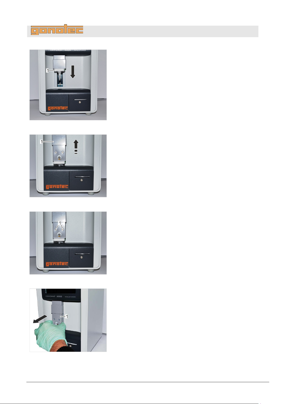
OSMOMAT 3000
basic
// OSMOMAT 3000
Fig.
3
Move elevator (
Fig.
4
Move elevator
Fig.
5. Remove the 2 mounting screws (
(SW
Fig.
6
Remove complete elevator cover (
129: Move elevator down
.
Fig. 129/1) down.
Servicing
.
cover (Fig. 130/1) up.
130: Move elevator cover up
Fig. 131/1) using Allen key
2).
131: Remove mounting screws
.
Fig. 132/1).
132: Remove elevator cover
Version 1.22 1/6/2016 97
Page 98
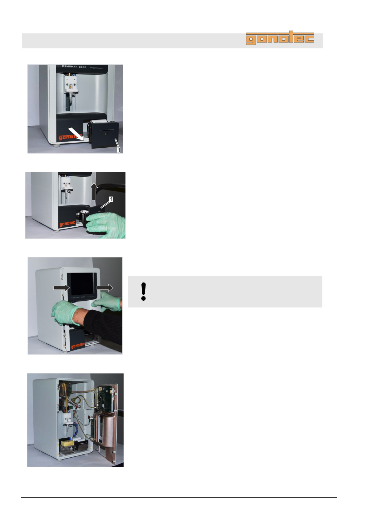
OSMOMAT 3000
basic
// OSMOMAT 3000
Fig.
7. Pull out printer (
(does not apply to OSMOMAT 3000
Fig.
8. Remove printer cover (
(does not apply to OSMOMAT 3000
9. Push printer back into device.
(does not apply to OSMOMAT
Fig.
10. Remove device front panel by pulling forward (
The
Fig.
11
Carefully place device front panel on its right side (
The device front panel is now removed.
Servicing
133: Pull out printer
Fig. 133/1) from device.
basic)
Fig. 134/1) by pulling up.
basic)
3000basic)
134: Remove printer cover
135: Remove device front panel
Fig. 135).
device front panel is secured to the housing by magnets.
NOTE!
Risk of damage to cables and connectors!
.
Fig. 136).
136: Device front panel open
98 Version 1.22 1/6/2016
Page 99
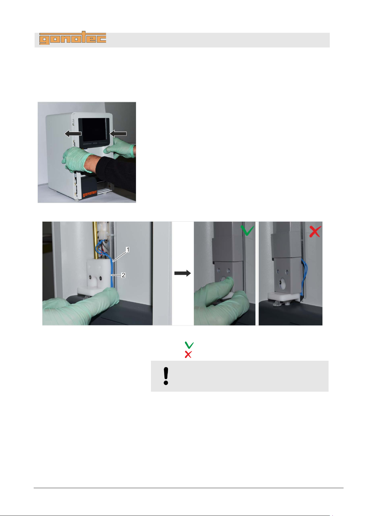
OSMOMAT 3000
basic
// OSMOMAT 3000
Install device front
Personnel:
Safety gear:
Materials:
Fig.
1. Install device front panel on device and push into
(
2. Pull out printer from device using handle.
(does not apply to OSMOMAT 3000
3. Install printer cover on printer and push down.
(does not apply to OSMOMAT 3000
The printer cover is now secured.
4. Push printer back into device.
(does not apply to OSMOMAT 3000
Fig.
1 Cable
2 Cable guide on temperature sensor
Correct cable routing
Incorrect cable routing
5
Route cables on temperature
(
Pay attention to correct cable routing.
panel
137: Install device front panel
Servicing
Service technician
Disposable lab gloves
Allen key SW 2
place
Fig. 137).
basic)
basic)
basic)
138: Elevator cover with correct cable routing
.
NOTE!
Risk of cable break!
sensor through cable guide
Fig. 138/2) and install elevator cover on device.
Version 1.22 1/6/2016 99
Page 100
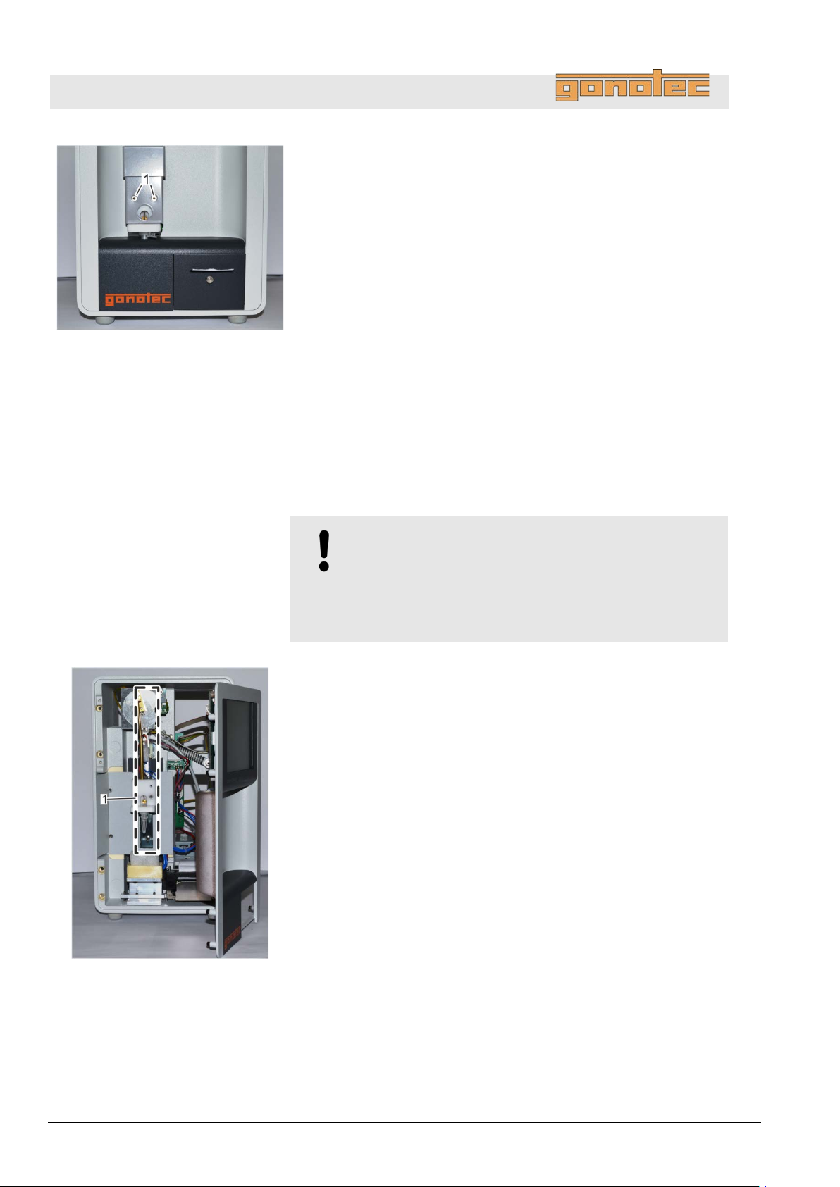
OSMOMAT 3000
basic
// OSMOMAT 3000
Fig.
6. Bolt elevator cover to
(
The device front panel is now installed.
Personnel:
Safety gear:
Materials:
Fig.
1
Power down device on rear side using on/off switch.
2. Remove device front panel (
Servicing
139: Tighten mounting screws
9.4 Lubricate elevator
Fig. 139/1).
User
Disposable lab gloves
Silicone spray
elevator using the 2 mounting screws
NOTE!
Risk of property damage due to wrong lubricant!
The use of lubricating grease can damage the elevator
guide.
- Only use silicone spray as lubricant.
.
on page 95).
140: Location of elevator guide
100 Version 1.22 1/6/2016
 Loading...