

Page 1

GO Metro Broadband Wireless
Getting Started
Technical Guide for WLP
Wireless LAN Pico Base Station
Version 2.2
Document #: WLP22070601-R1
Page 2

GO WLP Getting Started Guide
Trademarks and Licensing Agreement
© 2006 GO Networks, Inc. All rights reserved.
All information contained in this document is protected by international
copyright treaties. No information may be copied or reproduced without the
express written consent of GO Networks Inc.
GO Metro Broadband Wireless, Go MBW, WLAN Sector Base Station, WLS, GO
WLAN Pico Base Station, WLP, GO Wireless Network Controller, and WNC are all
trademarks of GO Networks Inc.
Any duplication, transmission by any method, or storage in an information
retrieval system of any part of this publication for other purposes other than
those stated above is strictly prohibited without the specific written permission
of GO Networks, Inc. This includes, but is not limited to, transcription into any
form of computer system for audio, text, print, or visual retrieval. All rights
under federal copyright laws and international laws will be strictly enforced.
All other trademarks and registered trademarks are the property of their
respective owners.
GO Networks Inc.
1943 Landings Drive • Mountain View, CA 94043 • USA
Tel +1.650.962.2000 • Fax +1.650.962.2010
Email [email protected]
Version 1.00
Page 3

FCC Compliance Status
The following information is for FCC compliance:
This device complies with Part 15 of the FCC Rules. Operation is subject to
the following conditions:
1. This device may not cause harmful interference, and
2. This device must accept any interference received, including
interference that may cause undesired operation.
This equipment has been tested and found to comply with the limits of a
Class B digital device, pursuant to Part 15 of the FCC Rules. These limits
are designed to provide reasonable protection against harmful interference
when the equipment is operated in a residential environment, this
equipment generates, uses, and radiates radio frequency energy, and if
not installed and used in accordance with the instructions, may cause
harmful interference. However, there is no guarantee that interference will
not occur.
To meet regulatory restrictions, the outdoor access point must be
professionally installed.
The Part 15 radio device operates on a non-interference basis with other
devices operating at this frequency when using its antennas. Any changes
or modifications not expressly approved by GO Networks could void the
user's authority to operate the equipment.
The antennas used for this transmitter must not be co-located or operating
in conjunction with any other antenna or transmitter.
All contents are Copyright © 2006 GO Networks, Inc. All rights reserved.
- Page 1 of 31-
Page 4

Table of Contents
Introduction ........................................................................................................................................3
Ke y P r o du c t Fe a t ur e s ............................................................................................................................3
Organization..............................................................................................................................................4
GO WLAN Pico Base Station (WLP)..................................................................................................5
WLP Package Components.........................................................................................................................5
WLP Safety Information...............................................................................................................................5
RF Exposure..............................................................................................Error! Bookmark not defined.
WLP Lightning Protector............................................................................................................................6
Installation..........................................................................................................................................7
Installation Process......................................................................................................................................7
Site Survey................................................................................................................................................7
Assembling and Mounting...........................................................................................................................8
Mounting the Antenna................................................................................................................................11
Cable Connections.....................................................................................................................................11
Grounding Cable......................................................................................................................................13
Ethernet Connection................................................................................................................................13
Power Connection ...................................................................................................................................13
Console Connection ................................................................................................................................13
Hardware and Connectors Installation Tools...........................................................................................13
Power Up and Software Configuration.....................................................................................................14
Post-installation Testing Procedure.........................................................................................................14
Configuring the WLP........................................................................................................................15
Connect and Access the WLP.................................................................................................................15
Configuring the Management Connectivity..............................................................................................17
Configuring the Radio Settings................................................................................................................17
Setting the Radio Data Rates..................................................................................................................17
Configuring Multiple SSIDs......................................................................................................................18
Enabling the Radio Interface....................................................................................................................19
Configuring the WDS...............................................................................................................................19
Configuring Authentication Types............................................................................................................22
Configuring the Radius Client in the WLP................................................................................................22
Configuring Privacy Methods...................................................................................................................23
Saving the Configuration..........................................................................................................................24
WLP Configuration Example....................................................................................................................24
Upgrading the WLP Software..........................................................................................................25
Appendix A: List of Acronyms........................................................................................................27
Appendix B: Wiring Specifications.................................................................................................29
All contents are Copyright © 2006 GO Networks, Inc. All rights reserved.
- Page 2 of 31-
Page 5

Introduction
GO Networks’ WLP device is the key enabler for the Metro Broadband
Wireless (MBW) Solution. Go Pico Cellu lar WiFi architecture offers a novel
topology for metro WiFi networks which relies on the strengths of
innovative XRF™ architectures. This architecture provides the coverage,
capacity, and scalability required to deliver next-generation services and
overcome the limitations of existing metro WiFi solutions.
The Go Networks’ Pico Cellular WiFi architecture is a highly scalable
Micro/Pico topology which provides unprecedented flexibility to service
providers deploying Metro WiFi networks.
Key Product Features
a. Robust Pico cellular WiFi solution
b. Separate accesses & backhaul radios delivering unmatched
bandwidth
c. xRF™ smart antenna engine for unmatched (360
capacity enhancements
o
) coverage and
d. Advanced automatic mesh
e. Designed for streetlight, wall, or pole deployment
All contents are Copyright © 2006 GO Networks, Inc. All rights reserved.
- Page 3 of 31-
Page 6

Organization
The GO Metro Broadband Getting Started Guide for the Wireless LAN Pico
Base Station (WLP) offers information and instructions for quickly installing
and configuring the WLP. The instructions and information are presented in
one volume as follows:
Introduction
GO WLAN Pico Base Station
Installation Process
WLP Component and Cable
Connections
Configuring the WLP
Upgrading the WLP Software
Appendix A
Appendix B
Contains introductory informat ion about the WLP.
Presents a general description and overview of
the WLP including content and safety procedures.
Describes the installation process for the WLP.
Describes the WLP component and cable
connections.
Describes how to configure the WLP.
Explains how to update the WLP software.
Lists the acronyms that appear in the manual.
Details the wiring specifications.
All contents are Copyright © 2006 GO Networks, Inc. All rights reserved.
- Page 4 of 31-
Page 7

GO WLAN Pico Base Station (WLP)
The GO WLAN Pico Base Station (WLP) complements the WLAN Sector
Base Station (WLS) by delivering street-level coverage and providing
capacity enhancements in dense metro areas over a single 802.11b/g
channel, while backhauling traffic over multiple 802.11a/b/g radios.
The WLP Base Station delivers omni-directional (360
retaining full xRF smart antenna engine functionality for enhanced capacity
and range.
WLP Package Components
The WLP package items are listed in Table 1:
o
) coverage while
DESCRIPTION REV QTY
Wall/Poll Mount Kit Assembly (new) 1.0 1
Connectors Kit for WLP Package 1.0 1
WLP unit 1.0 1
WLP Access Antenna 2.4GHz 7.4dBi Gain,
Omni 4
802.11a 10dBi Omni Antenna (Backhaul) 2
Streetlight Power Tap Adapter 1
Table 1: WLP package contents
Deployments of gateway devices connected by wire to an indoor
switch/router would include installation of a lightning protector. A lightning
protector is not supplied as part of the standard package. It can be
ordered from GO Networks as an accessory.
Specific installation may require different Power/Ethernet connections. See
WLP Component and Cable Connections
for more details.
All contents are Copyright © 2006 GO Networks, Inc. All rights reserved.
- Page 5 of 31-
Page 8

WLP Safety Information
RF Exposure
The WLP, an outdoor access point, is compliant with the requirements
set forth in CFR 47 section 1.1307, addressing RF Exposure from radio
frequency devices as defined in OET Bulletin 65. The outdoor access
point antennas should be installed to provide a separation distance of at
least 3 feet (1 meter) from humans
WLP Lightning Protector
A lightning protector is required when the WLP unit is installed in an
outdoor location and the Ethernet cable connects to an indoor network
device. The purpose of the lightning protection is to protect people and
equipment located indoors from lightning that might strike the WLP or its
outdoor cables. Therefore, the lightning protector device should be
installed indoors, as close as possible to the point where the cables enter
the building.
The lightning protector can also be installed outdoors, as long as the
cables that go from the lightning protector to the indoors are well
protected from lightning between the box and the building entrance.
Verify that you have shared grounding. GO Networks offers a lightning
protector that can be ordered separately.
All contents are Copyright © 2006 GO Networks, Inc. All rights reserved.
- Page 6 of 31-
Page 9

Installation Process
Installing the WLAN Pico Base Station involves the following steps:
1. Performing a Site Survey
2. Assemb ling and Mounting
3. Mounting the WLP unit
4. Connecting the Antennas
5. Connecting the c ables
6. Powering up the unit and configuring the software
7. Performing a Post-installation Testing Procedure to verify
connectivity and operation
Installation
Site Survey
Most wireless LANs include many access points installed in various
locations in an overlapping radio-cell pattern. It is important to carefully
position each access point’s positioning and the assignment of its radio
channels. Therefore, a site survey becomes an essential first step before
physically deploying the GO MBW WLP Pico Cellular Base Station solution.
Installation of the access points requires a backhaul to interface the
corporate network or Internet. This backhaul connection can be a mesh
configuration, an Ethernet-wired connection, or a third-party solution.
When using any method other then a wired connection, keep in mind the
WLP has to have a good reception on its BH side so it will not limit the
access-channel performance.
Conclude the site survey with a detailed plan of the MBW system
deployment. The system deployment plan should include WLP mounting
points and the routes for the power and backhaul cables.
Note: When mounting the WLP on a pole (or wall mount), the pole
should be able to support four times the weight of the WLP, as
well as the wind loading created by the WLP.
Since the mounting structure itself is a potential source of
interference, the cell should be mounted with at least 4 feet of
clearance between the antennas and the mounting structure.
All contents are Copyright © 2006 GO Networks, Inc. All rights reserved.
- Page 7 of 31-
Page 10
Assembling and Mounting
The universal mount is used to attach and secure the WLP to a wall, a
lamppost, or a variety of poles.
The WLP mounting consists of the following stages:
a. Securing the mounting brackets to a wall, lamp post, or pole.
b. Connecting the WLP unit to the brackets using the ‘L’ adaptor.
c. Aligning the WLP unit.
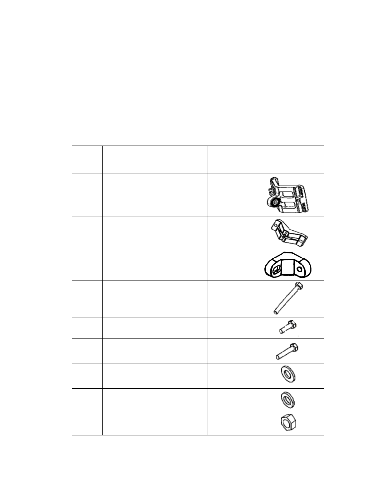
Table 2 lists the universal mount parts:
Item
No.
Description Qty Picture
A Wall/poll bracket 1
B Clamping bracket 1
C
WLP ‘L’ adapter wall/poll
mount
D Bolt M8x70 2
E Screw Hex Cap M8 x25 1
1
F Bolt M8x40 1
G Washer flat M8 3
H Washer spring M8 4
I Nut M8 1
All contents are Copyright © 2006 GO Networks, Inc. All rights reserved.
- Page 8 of 31-
Page 11
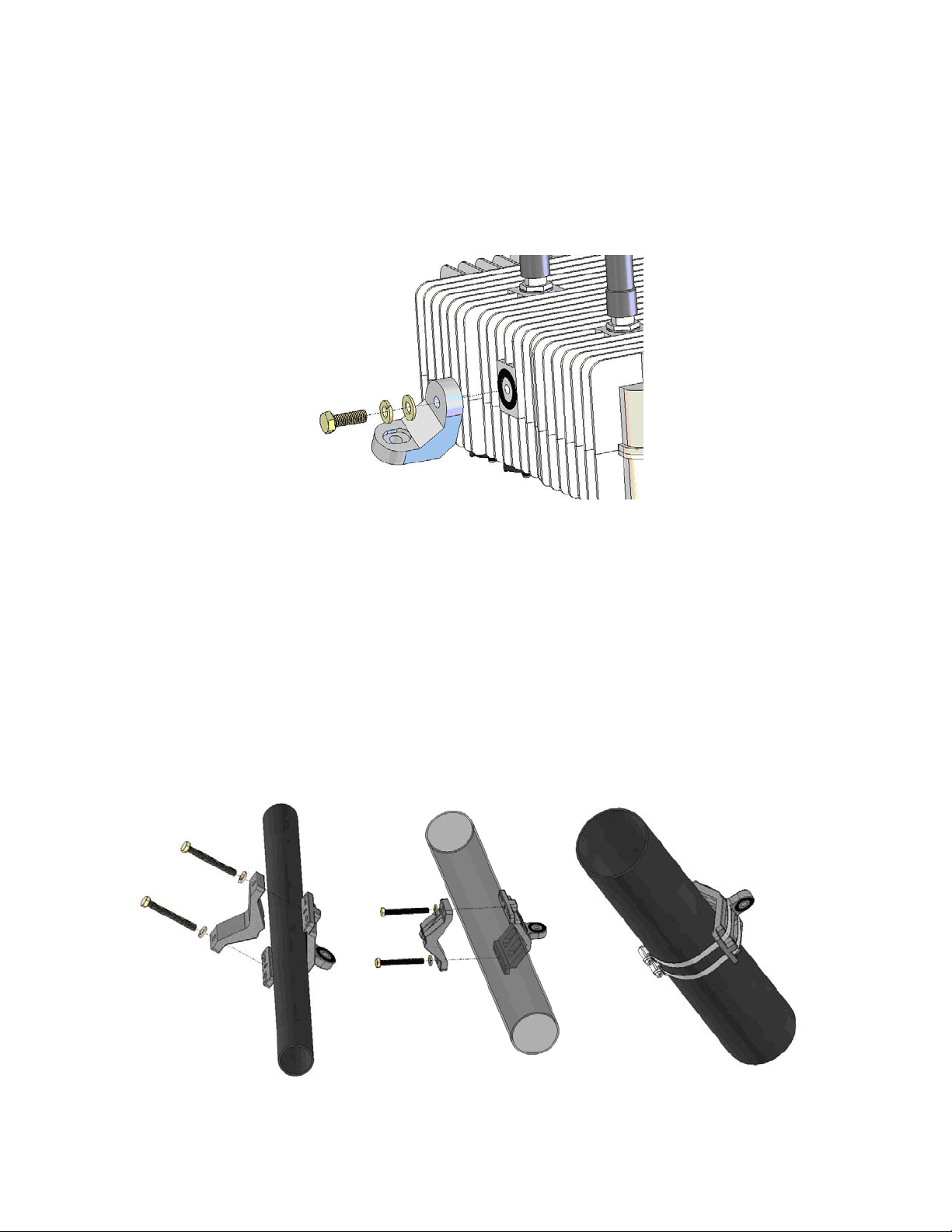
Table 2: Mounting Kit Part List
First connect the ‘L’ adaptor [C] to the WLP unit. As seen in Figure 1, the
‘L’ adapter is connected using an M8 [E] bolt, a washer spring [H], and a
flat washer [G]. You must connect the ‘L’ adaptor on its normal-hole side
and not on it grooved side.
Figure 1: Mount ‘L’ Assembly
After preparing the unit with the ‘L’ adaptor, install the brackets. Assembly
of the mounting brackets in a lamppost or a pole installation differs
according to the width of the pole. Use two M8 bolts [D] with spring
washers [H] to install the brackets onto narrow (1”–1.75”) and normal
(1.75”–3”) poles, as illustrated in Figure 2. For poles larger than 3” in
diameter, install the bracket using 13 mm width hose clamps (not supplied
with the unit).
Narrow pole
1"-1.75"
Normal pole
1.75"-3"
larg e p ole
Grat er then 3"
All contents are Copyright © 2006 GO Networks, Inc. All rights reserved.
- Page 9 of 31-
Page 12
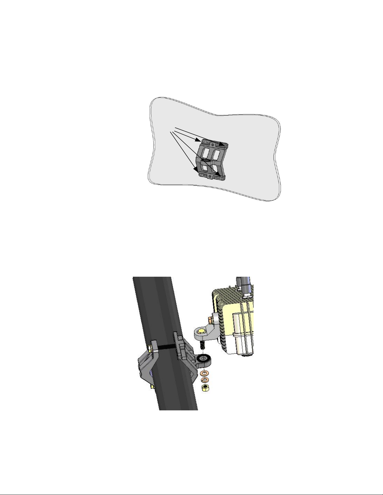
Figure 2: Pole Bracket Assembly
When mounting the WLP unit to a wall, use four 5 mm bolts to secure the
bracket [A], using the holes seen in Figure 3. Wall-mounting bolts are not
supplied with the unit.
Wall mounting holes
Figure 3: Bracket Wall Mounting
After assembling the brackets, mount the WLP unit on to the bracket as
seen in Figure 45. To accomplish this, use an M8 bolt [F] inserted to the
grooved side of the ‘L’ adaptor, a flat washer [G], a spring washer [H] and
a nut [I].
Figure 4: WLP Unit Mounting
All contents are Copyright © 2006 GO Networks, Inc. All rights reserved.
- Page 10 of 31-
Page 13
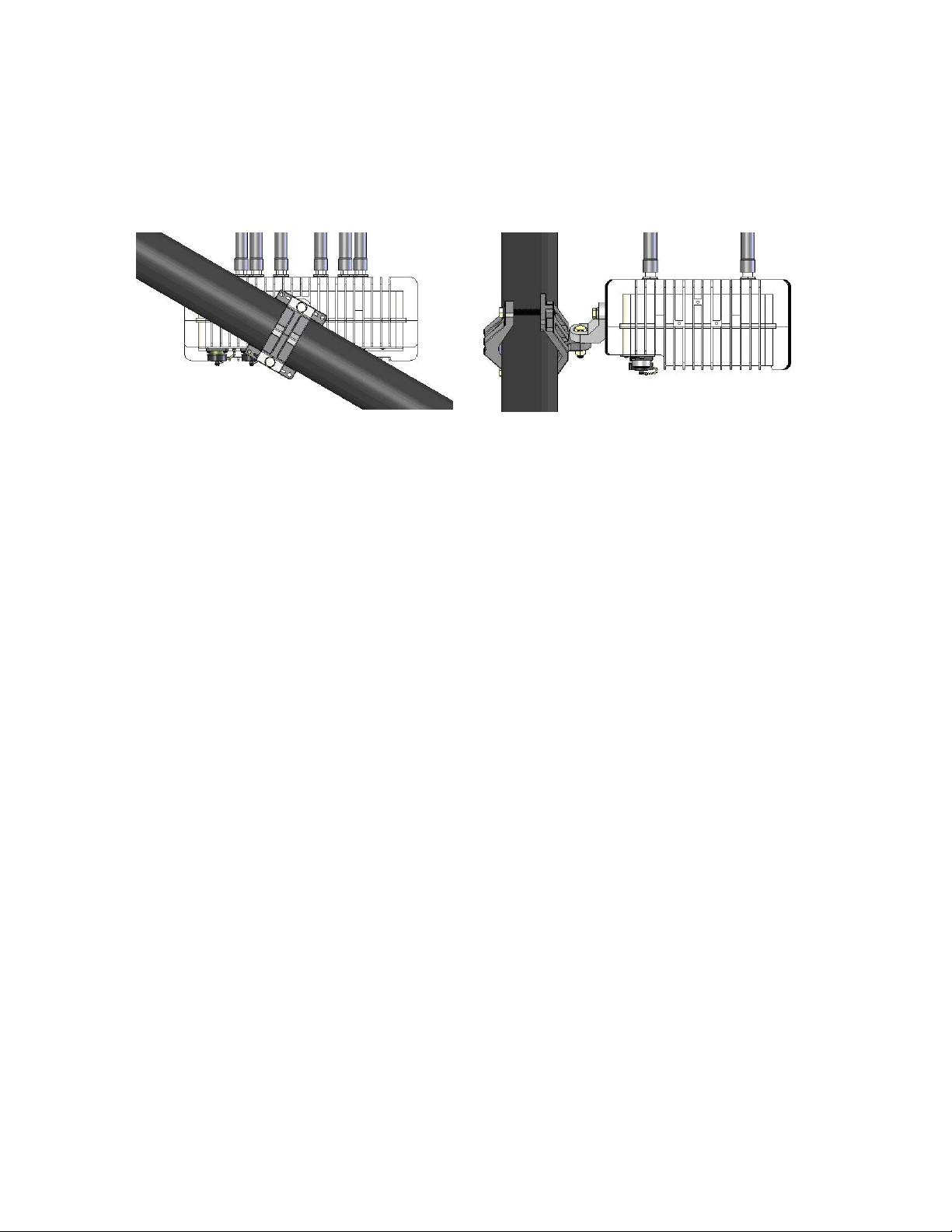
Once the WLP unit is mounted, release the bolts slightly and align the WLP
unit horizontally, as seen in Figure 56. When the unit is perfectly aligned,
firmly close all bolts, applying 120 lbs-inch of tilting torque.
Figure 5: Aligning the WLP
Mounting the Antenna
Integral N-male connectors are used to mount the antennas on top of the
WLP. The WLP holds four WiFi antennas for user access, operating on the
2.4 GHz band marked A1 to A4, and two antennas used for the mesh
networking connections, operating on the 5.8 GHz band marked B1 and
B2.
Screw all antennas into place by hand. Do not apply excessive force while
using any tools as this may damage the unit.
Cable Connections
The WLP unit connections are very simple and can be accomplished in only
a few minutes. When aligned, the WLP connecters are at the bottom of the
unit.
Cable requirements are often unique to the location and deployment
topology of each installation. As a result of this limitation, the Ethernet and
grounding cables are not included in the installation kit.
The following cables are required to install the WLP unit and should be
connected in the following order:
1. Grounding Cable:
Provides the necessary safety functions.
2. Ethernet Cable (required only in units connected to the wired
network):
CAT5 shielded; maximum length: up to 100 meters
All contents are Copyright © 2006 GO Networks, Inc. All rights reserved.
- Page 11 of 31-
Page 14

3.
Power Cable:
The supplied AC power cable is deigned to connect directly to a
lamppost power-tap feed.
4. RS-232 Console Cable: (The device might be pre-configured, so
console connection isn’t required in the installation site.)
To connect the WLP to a console (laptop computer) for
configuration.
All contents are Copyright © 2006 GO Networks, Inc. All rights reserved.
- Page 12 of 31-
Page 15
Grounding Cable
The grounding cable should be connected to the grounding screw at the
bottom of the unit. Use a 1 mm / 18 awg grounding cable.
Note: Connect the grounding cables before connecting any other cables.
Do not remove the grounding cable when other cables are
connected.
Ethernet Connection
Ethernet connection is used for wired backhaul connection or an
interface to a third party wireless BH solution.
Power Connection
Figure 6 illustrates how the WLP unit is connected to main outlet via the
Auxiliary Power Adapter.
Figure 6: Power Connection
Release the photo-cell (also called the photo-control) installed on the pole.
Insert the Auxiliary Power Adapter instead of the photo-cell. Connect the
Auxiliary Power Adapter cable to the power connector of the WLP.
Console Connection
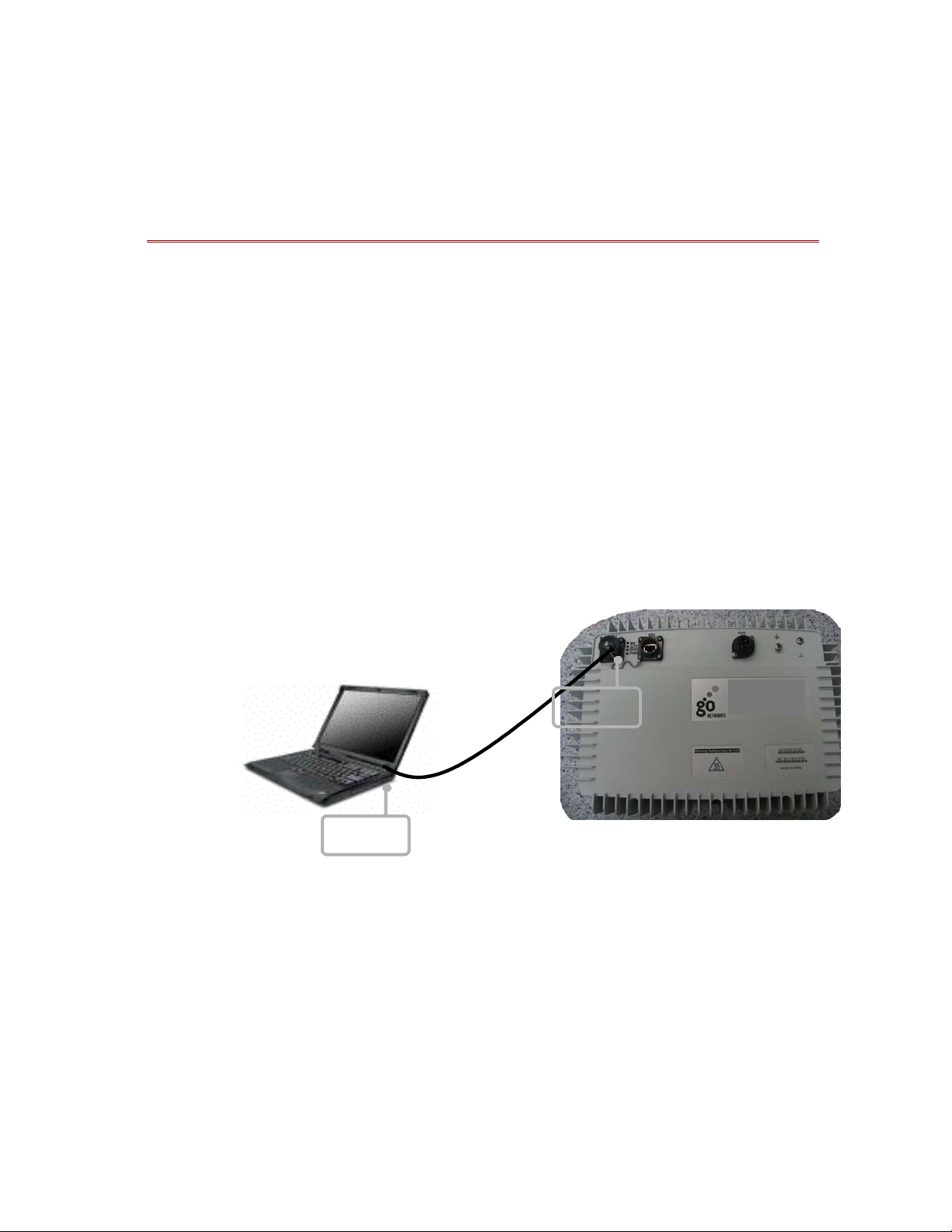
Figure 7 illustrates the RS-232 cable connections used to connect the WLP
to a console (notebook computer to configure the WLP).
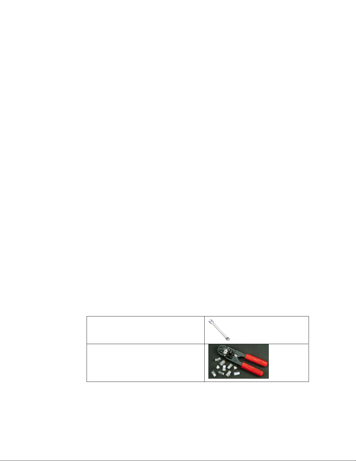
Hardware and Connectors Installation Tools
The following tools and equipment are required to mount the WLP on a pole.
Table 3: Mounting Tools and Equipment
Ratchet (13 mm.)
13 mm.
RJ45 crimp tool
HT-210A
All contents are Copyright © 2006 GO Networks, Inc. All rights reserved.
- Page 13 of 31-
Page 16

Power Up and Software Configuration
The WLP unit is normally mounted on a high pole (or wall) where it is
inconvenient to configure. However minimal connectivity must be verified
so the unit can later be configured and monitored from the ground. In
order to verify connectivity when installing the device, root devices must
be installed and powered up first.
The connectivity of the root device can be verified by the Ethernet ACT
LED. The root device MESH LED should also be on, indicating the device is
ready to connect wirelessly. When powering up a non-root device, the
MESH LED should be lit to indicate the device is connected wirelessly. WLP
boot time is about 2.5 minutes. The MESH LED indicator will light up after
the boot is completed.
Post-installation Testing Procedure
The purpose of the post-installation testing procedure is to verify
connectivity between the WLP and the network.
It is recommended that you perform the following tests:
1. Ping the device.
2. Establish telnet access and ping the access controller or the network
from the WLP unit CLI.
All contents are Copyright © 2006 GO Networks, Inc. All rights reserved.
- Page 14 of 31-
Page 17
Configuring the WLP
Following is a brief overview of the main CLI commands that are used to
configure the WLP. A configuration example follows the detailed list of
configuration commands. These and other CLI commands are detailed in
the GO MBW CLI Reference Guide.
Connect and Access the WLP
Initial configuration of the WLP is done using a serial cable. A standard
RS232-interface DB-9 cable is connected to the COM port of a laptop or a
PC to the WLP unit’s console port. For more information regarding the
serial cable, see Appendix B, Wiring Specifications.
Once the WLP IP address is configured, the rest of the configuration can be
done using Telnet via the network.
WLP
Notebook PC
Consol Port:
Consol Port:
RS232
RS232
Consol Port:
Consol Port:
RS232
RS232
Figure 7: Connect and Access the WLP
- Page 15 of 31-
All contents are Copyright © 2006 GO Networks, Inc. All rights reserved.
Page 18
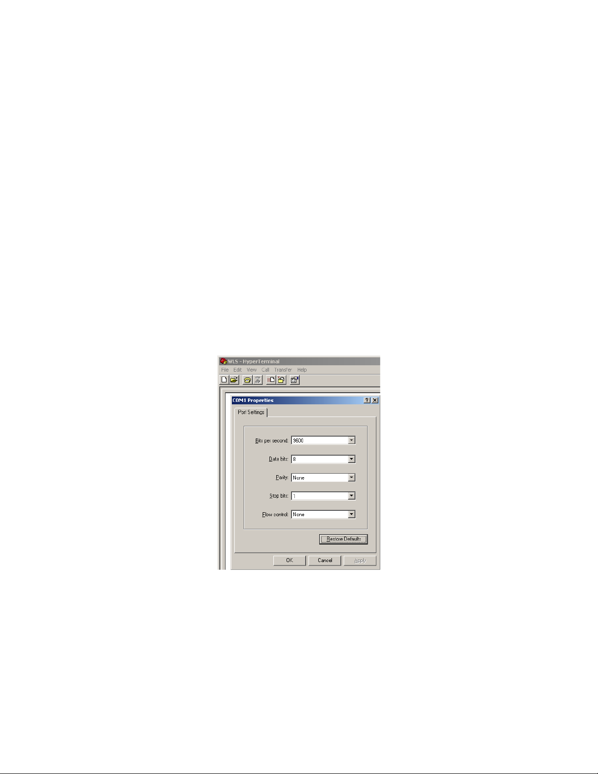
Once the cable is connected, you can then operate a terminal program,
such as HyperTerminal. The PC port should be configured as follows:
d. Baud rate = 9600
e. Data bits = 8
f. Parity = none
g. Stop bits = 1
h. Flow control = None
To use HyperTerminal:
From the Start menu:
1. Select All Programs > Accessories > Communications >
HyperTerminal.
2. Define a new connection.
3. Right-click and select Properties. Set or verify the above values.
4. Click OK.
Figure 8: HyperTerminal
5. Establish the connection between the WLP and the laptop (or PC).
6. Log in using the predefined “super” user (user: super; password:
super).
The user name determines what authorization level the operator has and,
All contents are Copyright © 2006 GO Networks, Inc. All rights reserved.
- Page 16 of 31-
Page 19

in turn, determines whether you can view configuration and operation
parameters, or implement changes. A new user and password name
should be added; however this default name and password can be used for
the initial configuration.
The default system name for the unit is set to WLS.
Configuring the Management Connectivity
Configuring the management connectivity involves setting the Fast
Ethernet connection as well as defining the default gateway. These
procedures are detailed in the following section.
Define the static IP address and the subnet mask on the same network
through which you connect to the WLP. You can use the CLI command:
configure ip address <ip address>, as shown below:
configure ip address 192.168.30.102 255.255.255.0
The default is IP is fixed on 192.168.0.10
Note: If you are using DHCP client on the first gateway, you do not
need to configure the default gateway.
Default Gateway
Define the default gateway by using the Configure mode (consult with your
network administrator). You can use the CLI command:
configure ip default-gateway <ip address> disable/enable, as
shown below:
configure ip default-gateway 192.168.30.254
Note: If you are using DHCP client on the first gateway, you do not
need to configure the default gateway.
Configuring the Radio Settings
By default, the channel is configured to channels 1 (2.412 GHz). You can
define different configurations for each channel by using the following CLI
command:
configure interface dot11Radio 0 channel 6
Setting the Radio Data Rates
All contents are Copyright © 2006 GO Networks, Inc. All rights reserved.
- Page 17 of 31-
Page 20

By default, the channels are defined for use in a mixed mode. You can
select a rate per channel for one of two states: g or mixed (a combination
of g and b). The following CLI command syntax is used:
configure interface dot11Radio 0 mode [g | mixed]
Configuring Multiple SSIDs
The SSID is a unique identifier that wireless networking devices use to
establish and maintain wireless connectivity. Multiple access points on a
network or sub-network can use the same SSID. Configuring the same
SSID across multiple APs will enable the users to roam between them
seamlessly. SSIDs are case sensitive and can contain up to 32
alphanumeric characters.
You can configure up to 16 SSIDs on your WLS. Each SSID has its
unique privacy configuration and unique VLAN ID. VLAN-ID 0 represents
no VLAN tag.
Each SSID can be defined as either a Broadcast SSID (BSSID) or a
hidden one. Passive scanning clients will not detect a hidden SSID,
since it doesn’t transmit any beacon frames. Configuring multiple
BSSIDs on the same interface is known as creating a Virtual Access
Point. A Virtual Access Point is a logical entity that exists within a
physical access point. When a single Physical AP supports multiple
Virtual APs, each Virtual AP appears to stations to be an independent
Physical AP, even though only a single Physical AP is present.
Note: SSIDs, VLANs, and encryption schemes are mapped together
on a one-to-one-to-one basis. One SSID can be mapped to one
VLAN, and one VLAN can be mapped to one encryption
scheme.
Define the SSID parameters. This configuration stage is common to SSID
to be used as primary (broadcast) or hidden. In the following example,
three SSID’s are defined as GO-WLS1, GO-WLS2, and GO-HIDDEN, each
with its own VLAN-ID, and no privacy.
WLS> configure ssid 1 name GO-WLS1 vlan 0 privacy-method none
type bssid
WLS> configure ssid 2 name GO-WLS2 vlan 0 privacy-method none
type bssid
WLS> configure ssid 3 name GO-HIDDEN vlan 1 privacy-method
none type hidden
The next step is to apply the defi ned SSIDs for the interface:
WLS> configure interface dot11Radio 0 ssid add 1
WLS> configure interface dot11Radio 0 ssid add 2
WLS> configure interface dot11Radio 0 ssid add 3
All contents are Copyright © 2006 GO Networks, Inc. All rights reserved.
- Page 18 of 31-
Page 21

Enabling the Radio Interface
By default, the WLP radio is disabled. You can, however, choose to enable
it using the following CLI command syntax:
configure interface Dot11Radio 0 [disable | enable ]
Note: You can’t enable the wireless inter face until at least one BSSID
is attached to it.
Configuring the WDS
WDS protocol is used to support wireless backhauling and meshing of WLP
and CPE units. WDS is supported over both the 2.4 GHz access radio and
the 5 GHz backhaul radio.
In the section below, the following terms will be used:
i. Peer — A WDS unit. An AP, which support the WDS feature.
j. Root — A peer that is connected to the Ethernet.
k. Hop1 — A “non-root” peer that is connected to a root.
l. Hop2/3 … — A “non-root” peer that is connected to a Hop1/2 …
m. Parent-Child — Two peers which are defined by the WDS
connection. The parent is the peer giving Ethernet access to the child
peer.
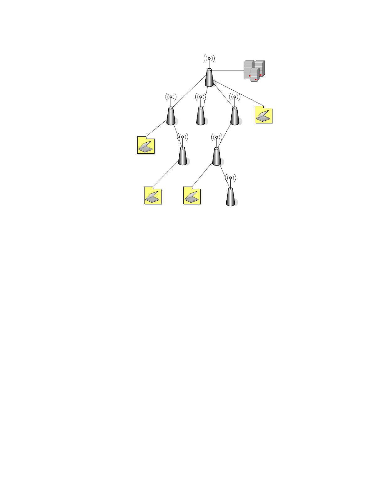
The WDS topology is based on a tree structure as illustrated in Figure 9,
meaning, in a given time each peer has one Parent. Root has no Parent
since it is the head of the tree. WMG and third party CPEs will normally
connect at the bottom of the tree. Clients may connect to any AP in the
tree.
All contents are Copyright © 2006 GO Networks, Inc. All rights reserved.
- Page 19 of 31-
Page 22
Domain
ROOT /FATHER
HOP1/SON HOP1/SON/FATHER
Hop2/son
Figure 9: WDS Tree
The WLP supports two modes of WDS operation: Manual and automatic
topology detection.
Manual Mode — Connection between two peers is done by manually
entering each peer MAC address. Once the MAC address has been entered,
the two peers are WDS-connected.
Automatic Mode (AWDS) — Connection between two peers is done by
automatically discovering the father and establishing the connection
between the two peers.
In automatic mesh topology detection (AWDS) mode, the WLP will route
the traffic using the best route when more then one route exists. In a
similar way, the AWDS will recover from a fault by selecting an
alternate route when needed.
A non-root WDS WLP is not connected to the wired LAN. A non-root device
relies on the WDS mesh network for connectivity. A non-root WDS WLP
routes to the root WDS WLP with which it has the best connectivity.
However, you can manually override the AWDS by specifying the path to
which the WDS routes.
It is important to note that the number and quality of hops will determine
the network performance. In most cases, the physical deployment of the
devices is the limiting factor in route selection.
All contents are Copyright © 2006 GO Networks, Inc. All rights reserved.
- Page 20 of 31-
Page 23

WDS root configuration is controlled by:
configure wds root [ true | false ]
To display the current WDS configuration use:
show wds params
WDS is always used on the BH radio while the access radio can be
configured to use as Access-only, pure backhauled, or mixed operation by
the following command:
configure interface dot11Radio 0 service [access | backhaul |
both]
To activate the automatic topology detection mode (meshing mode) the
user has to enable this mode at both devices he wishes to connect and
configure them to the same radio channel. Automatic WDS topology
detection is currently supported on the BH radio or the access radio. Trying
to configure both radios to automatic mode will result in an error message.
To enable automatic mode use:
configure interface [dot11radio | BHRadio ] 0 wds-autodiscovery enable
Once automatic mode has been enabled, the route candidates can be
viewed using:
show WDS candidates
The current parent, active children, and static-defined peers can be viewed
using:
show WDS nodes
All contents are Copyright © 2006 GO Networks, Inc. All rights reserved.
- Page 21 of 31-
Page 24

To configure the WDS connection manually, use:
configure wds add peer <MAC Address>
Note: This command is used only for non-root WLP.
Note: Manual configuration can result in network loops.
The WDS connection can be protected by configuring the WDS privacy. The
user must configure all the units he wishes to connect with identical
privacy settings. WDS privacy is configured by:
configure interface [BHRadio | Dot11radio] 0 wds-privacy {
none | { wep key { 40 | 104 } < key hex(10|26) > } | { wpa
passphrase < passphrase string(8-63) > } }
For example, configuring WEP privacy for the BHRadio will use:
configure interface BHRadio wds-privacy wep key 40
11:22:33:44:55
Configuring Authentication Types
In the most common 802.1X WLAN environments, the WLP units defer to
the Radius server to authenticate users and to support particular EAP
authentication types. The Radius server handles these functions, and
provides crucial authentication and data-protection capabilities according
to the requirements of the EAP authentication type in use. The Radius
client runs on the WLP device and sends authentication requests to a
central Radius server, which contains all user authentication and network
service access information. The Radius server is normally a multi-user
system running Radius server software (such as developed by Microsoft or
other software vendors).
The wireless client device and Radius server on the wired LAN use 802.1x
and EAP to perform mutual authentication through the WLP.
1. The Radius server sends an authentication challenge to the client.
2. The client uses a one-way encryption of the user-supplied password
to generate a response to the challenge and sends that response to
the Radius server.
3. Using information from its user database, the Radius server creates
its own response and compares that to the response from the client.
When the Radius server authenticates the client, the process repeats in
reverse, and the client authenticates the Radius server.
Configuring the Radius Client in the WLP
All contents are Copyright © 2006 GO Networks, Inc. All rights reserved.
- Page 22 of 31-
Page 25

Your WLP must be configured to support the Radius server communication.
At a minimum, you must identify the Radius server software and define
the method lists for Radius authentication. Alternatively, you can define
method lists for Radius authorization and accounting.
Identifying the Radius Server
WLP-to-Radius server communication involves several components:
a. IP address
b. Authentication destination port
c. Accounting destination port
d. Key string
You should identify the Radius security server’s IP address and specific
UDP port numbers. The combination of the IP address and the UDP port
number creates a unique identifier.
A Radius server and the access point use a shared secret text (key) string
to encrypt passwords and exchange responses.
You can configure the Radius client in the WLP by using the following
command:
configure radius-server [primary | secondary] [authentication |
accounting] <port 1 – 65535> host <IP address> key <secret 5 –
64 string> enable
Configuring Privacy Methods
The privacy (encryption) scheme is configured per ESSID.
Using WPA Key Management
WiFi Protected Access (WPA) is a standards-based, interoperable security
enhancement that strongly increases the level of data protection and
access control for existing and future wireless LAN systems. It is derived
from and will be forward-compatible with the upcoming IEEE 802.11i
standard. It includes two new data-co nf identiality protocols (TKIP and
AES-CCMP).
WPA leverages TKIP and AES-CCMP (Temporal Key Integrity Protocol and
Cipher Block Chaining Message Authentication Code Protocol) for data
protection and 802.1X for authenticated key management.
WPA1 and WPA2 offer a high level of assurance for end users and network
administrators that their data will remain private and that access to their
networks will be restricted to authorized users.
WPA key management supports two mutually exclusive management
types:
All contents are Copyright © 2006 GO Networks, Inc. All rights reserved.
- Page 23 of 31-
Page 26

e.
WPA-Extensible-Authentication-Protocol (WPA-EAP): Using
WPA-EAP key management, the client and the authentication server
authenticate each other using an EAP authentication method, and
the client and server generate a Pairwise Master Key (PMK).
f. WPA-Pre-shared key (WPA-PSK): Using WPA, the server
generates the PMK dynamically and passes it to the WLP. Using
WPA-PSK, however, you configure a pre-shared key on both the
client and the WLP, and that pre-shared key is used as the PMK.
You can configure the WPA key management in the WLP using the
following command.
configure privacy wpa { { < ssid integer(1-16) > [ passphrase <
passphrase string(8-63)> ] [ key-mngmnt { eap | psk } ] } | { [
gtk-interval < interval integer(30-42949672) > ] [ dataencryption { tkip | aes } ] [ protocol { wpa1 | wpa2 | wpa2only
} ] [ preauthentication { enable | disable } ] } }
Saving the Configuration
Once you have modified the existing con f iguration file, you s hould save it
for future use. To do this, issue the following CLI command:
copy running-configure startup-configure
WLP Configuration Example
WLP > configure ip address 192.168.30.102 255.255.255.0
WLP > configure ip default-gateway 192.168.30.254
WLP > configure interface dot11Radio 0 channel 1
WLP > configure ssid 1 name GO-WLP vlan 0 privacy-method none type
bssid
WLP > configure interface dot11Radio 0 ssid 1 add
WLP > configure interface dot11Radio 0 mode mixed
WLP > configure interface dot11Radio 0 enable
WLP > copy running-config startup-config
All contents are Copyright © 2006 GO Networks, Inc. All rights reserved.
- Page 24 of 31-
Page 27

Upgrading the WLP Software
Periodically, new software upgrades are released in order to provide
feature enhancements and maintenance. Following is one method you can
use to update the software:
g. Initiate the network download using a TFTP download server.
Note: The WLP unit has two banks in the Flash memory (sw0, sw1).
By default, the WLP will startup the software image from the
sw1 bank.
Initially, when you download the new software image, the older version is
automatically transferred to sw0 bank, and the new software image is
transferred to sw1 bank.
Upgrade Example
WLP>
WLP> import image from tftp [IP ADDRESS] [File Name]
WLP> show messages software-download
Software download started.
Verifying server and path.
TFTP path OK.
Flash erase started.
Flash erase finished.
Download started from 192.168.30.103 gapsw-1.3.5.11995-Beta-
[email protected].
Download finished.
Verification started.
Verification passed.
Writing to environment.
Software download finished.
Note: It is important to reload the system after upgrading the WLP
software for the changes to be applied and the new software to
become operational.
You may need to copy a new image to the Flash memory whenever a new
image or maintenance release becomes available.
All contents are Copyright © 2006 GO Networks, Inc. All rights reserved.
- Page 25 of 31-
Page 28

To copy a new image into Flash memory (write to Flash
memory):
a. Use the import image from tftp command.
b. The system is now ready to be reloaded. After reload, the system
will operate with the new image.
- Page 26 of 31-
All contents are Copyright © 2006 GO Networks, Inc. All rights reserved.
Page 29

W
Appendix A: List of Acronyms
Acronym Explanation
802.11 A family of specifications related to wireless networking,
including: 802.11a, 802.11b, and 802.11g.
AP Access Point. The hub of a wireless network. Wireless
clients connect to the access point, and traffic between
two clients must travel through the access point. Access
points are often abbreviated to AP
BSSID Broadcast Service Set Identifier
DHCP Dynamic Host Configuration Protocol. A protocol which
enables a server to automatically assign an IP address to
clients so that the clients do not have to configure the IP
addresses manually.
EAP Extensible Authentication Protocol. A standard form of
generic messaging used in 802.1X.
ESSID EGOed Service Set Identifier
PMK Pairwise Master Key
SSID Service Set Identifier, a set of characters that give a
unique name to a WLAN.
TKIP Temporal Key Integrity Protocol
VLAN Virtual Local Access Network
WDS Wireless Distribution System
WEP Wired Equivalent Privacy. An encryption system created to
prevent eavesdropping on wireless network traffic.
WLP Wireless Base Station. Access point of the GO Networks MB
solution.
WNC Wireless Network Controller of the GO Networks MBW
solution.
WPA WiFi Protected Access. A modern encryption system created
to prevent eavesdropping on wireless network traffic. It is
considered more secure than WEP.
All contents are Copyright © 2006 GO Networks, Inc. All rights reserved.
- Page 27 of 31-
Page 30

Acronym Explanation
WPA-EAP
WPA-Extensible Authentication Protocol
WPA-PSK WPA-Pre-shared key
- Page 28 of 31-
All contents are Copyright © 2006 GO Networks, Inc. All rights reserved.
Page 31

Appendix B: Wiring Specifications
Table 4: Console Port Signaling and Cabling with a
DB-9 Adapter for the WLP Unit
Console Port
(DTE)
RJ-45-to-RJ-45
Straight
Cable
RJ-45 to
DB-9
Terminal
Adapter
Console
Device
Signal DB-9 Pin RJ-45 Pin RJ-45 Pin Signal
CTS 8 1 1 No connection
DSR 6 2 2 No connection
GND 5 3 3 No connection
GND 5 4 4 GND
TxD 3 5 5 RxD
RxD 2 6 6 TxD
DTR 4 7 7 No connection
RTS 7 8 8 No connection
All contents are Copyright © 2006 GO Networks, Inc. All rights reserved.
- Page 29 of 31-
 Loading...