

Page 1
INSTRUCTION
MODEL: GL-1
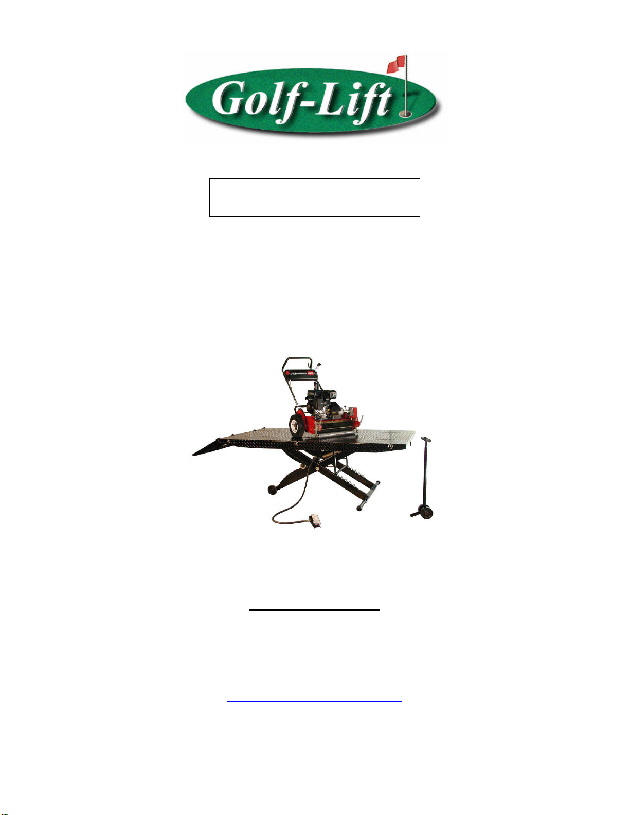
1,000-Lbs. Capacity Equipment Lift
GOLF-LIFT
2950 S.E. LOOP 820 FORT
WORTH, TX 76140
TOLL FREE: 800-788-9789
WWW.GOLF-LIFT.COM
Page 2
WARNING: READ THIS INSTRUCTION
BOOK COMPLETELY BEFORE OPERATING
THE LIFT
THIS IS A 1,000-LBS. CAPACITY EQUIPMENT LIFT. FAILURE TO
FOLLOW ALL SAFETY AND SERVICE PRECAUTIONS MAY
RESULT IN SERIOUS PERSONAL INJURY AND/OR PROPERTY
DAMAGE.
BASIC SPECIFICATIONS
GL-1
Length 93”
Width 48”
Full Raise 33”
Fully Lowered 7-1/4”
Weight Capacity 1,000 lbs
Inspection upon receipt of the lift
1. Always inspect the lift for freight damage and make note of any damage on the bill of
lading.
2. In case of freight damage, call the truck line immediately and report the damage as a
freight claim.
Final Set-Up for model GL-1
This lift is more than 90% factory pre-assembled. The following steps will guide you
through the final set-up.
1. Unpack the lift from the shipping skid. With the lift table up side down, connect the air
hose to the air cylinder (Part # 26).
2. After tightening the hose to the cylinder, flip the lift over with the table surface up.
Page 3

3. Connect the other end of the air hose to the foot-operated valve. Then connect the footoperated valve to 100 PSI air supply. DO NOT USE AIR SUPPLY WITH PRESSURE
MORE THAN 100 PSI.
4. Release the safety bar by pushing the handle down. Operate the foot valve by stepping
on the foot pad forward to raise the lift. The safety bar should engage the ladder
automatically while lift is rising. Step on the footpad again to set the pad in middle
position to stop the lift when it reaches the desired height. ALWAYS LOWER LIFT IN
THE NEAREST LOCKED POSITION BEFORE BEGINNING WORK. NEVER
USE THE LIFT UNLESS YOU ARE IN A LOCKED POSITION. The lift should
never be left unattended while attached to air pressure. Disconnect the air pressure when
lift is not attended by qualified persons.
5. Install the approach ramp by dropping it into the holes punched on the rear edge of the
table.
The final Set-Up for the GL-1 model is complete
Page 4

Final Set-Up for model GL-1
After you finished the steps for the GL-1
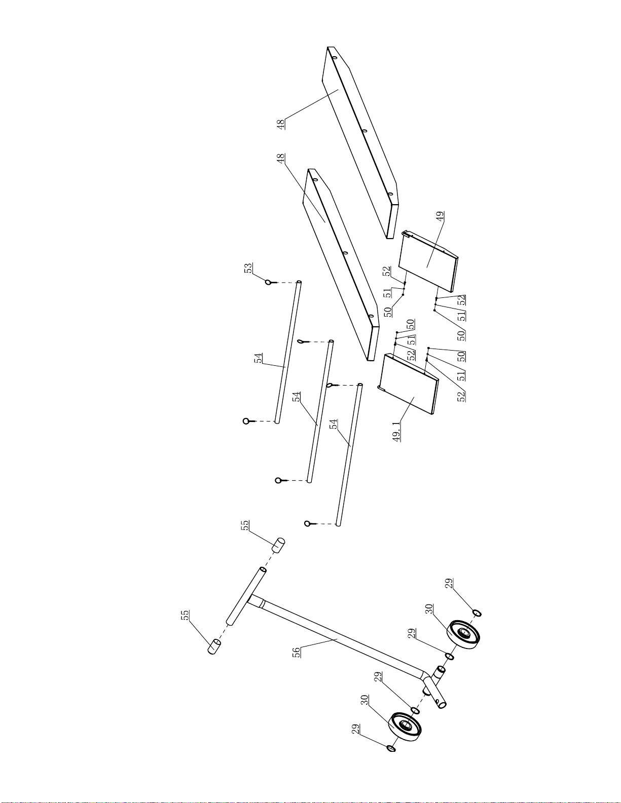
7. Run the Extension panel tubes (Total Three, Part # 58) through the holes on the side of
the table. Install the side extensions onto the protruding tubes. Using the clips supplied
(part # 59) to secure the tubes.
8. Drop the ramps for the side extensions in place as shown above.
9. Run the Stabilizing tube through the square tube in the bottom of the lift. Secure it with
screws supplied (parts # 64)
The final Set-Up for the GL-1 model is complete
Page 5
9
Page 6
41
42
43
40 41
39
5
19
4
3836
35
17 17 18
26
28
16
3 16 18
25
24
10
8
7
11 12
9
11
22
23
12
22
24
27
1
27
44
2
34
3029 29
46
46
444547
16
31323332
31
16
15
14
13
10
2011
21
106016
6
11
10
12
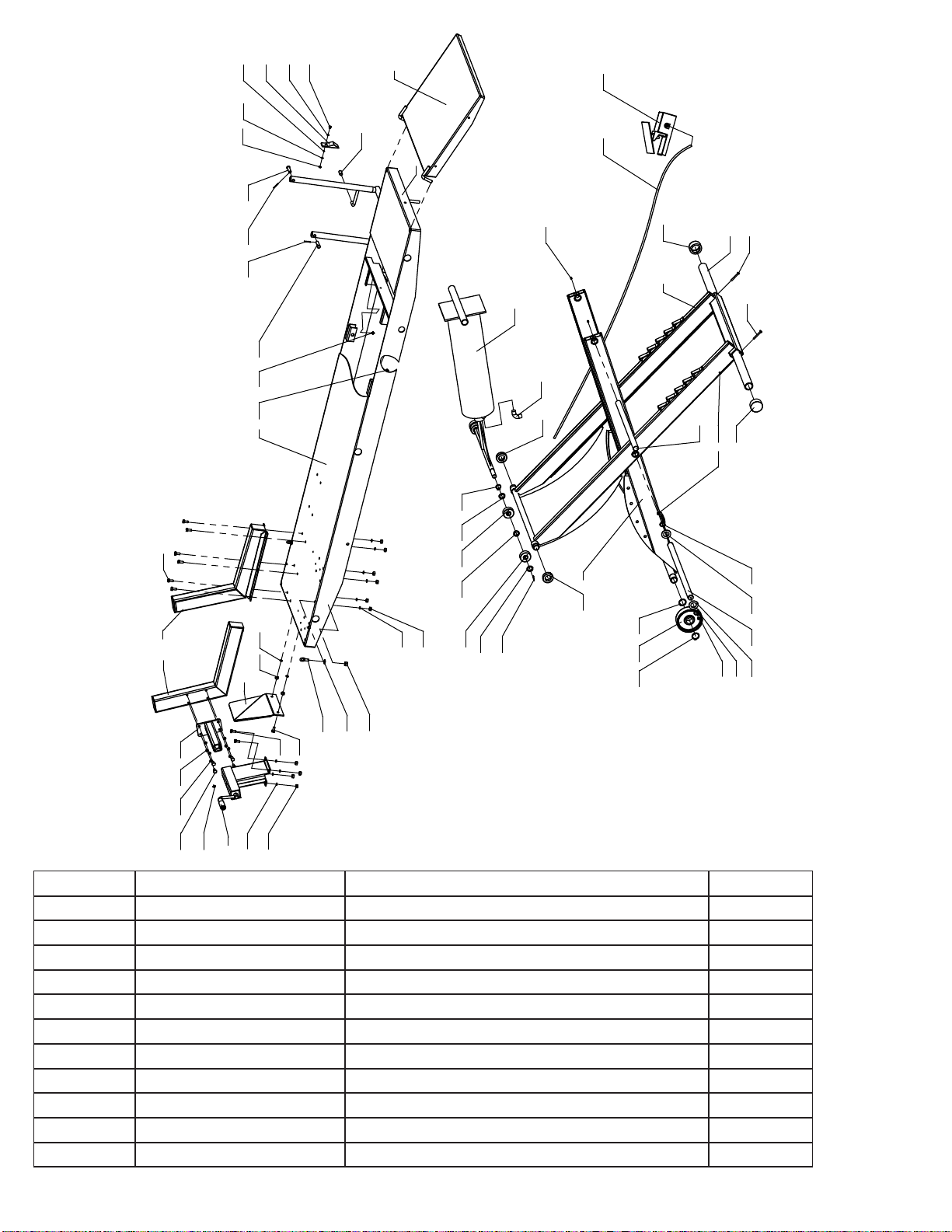
Item Part Number Description Qty
1 AL-1000G Scissor A-Outside 1
2 AL-2000G Scissor B-Inside 1
3 AL-3000 Lift Table-Motorcycle lift (only) 1
4 AL-4000 Lock Bar 1
5 AL-5202 Center,Approach Ramp B 1
6 AL-5400 Vise Clamp Handle-Assy 1
7 AL-5302 Vise,Moving Jaw-Assy 1
8 AL-5301 Vise,Stationary Jaw 1
9 AL-5604 Wheel Stop 1
10 B10-8×20 Bolt M8×20 16
11 B40-8 Lock Washer Ø8 16
10
Page 7
12 B30-8 Nut M8 12
13 B27-10×20 ‘Tie Down’’ Eye Bolt M10×20 2
14 B41-10 Flat Washer Ø10 2
15 B30-10 Nut M10 2
16 B85-6 Grease Zerk M6 5
17 B52-3×30 Cotter Pin Ø3×30 2
18 B53-12×45 Pin(B) Ø12×45 2
19 AL-4004 Plastic Grip/Safety Release 2
20 AL-5303 Moveable Vise Extension 1
21 B41-10 Flat Washer Ø10 4
22 AL-6006 Bearing/Cylinder 4
23 AL-6010 Spacer 2
24 B41-18 Flat Washer Ø18 4
25 B60-19 C-clip Ø19 2
26 YG09-9100 Air Cylinder 1
27 AL-6007 Bearing/Scissor 2
28 YG09-9106 Fitting 1
29 B60-32 C-Clip Ø32 4
30 AL-5501 Wheel 2
31 B60-25 C-Clip Ø25 2
32 AL-6005 Washer 2
33 AL-6003 Shaft/Scissor pivot 1
34 AL-6002 Shaft/Scissor pivot 1
35 B21-6×8 Set Screw M6×8 2
36 YG09-9301 Air Hose 1
38 YG09-9300 Foot-Operated Valve 1
39 B30-5 Nut M5 1
40 B40-5 Lock Washer Ø5 1
41 B41-5 Flat Washer Ø5 2
42 AL-6001 Lock Bar Holder 1
43 B10-5×16 Bolt M5×16 1
44 AL-5603 End Cap,Stabilizing Tube 2
45 AL-5602 Stabilizing Tube 1
46 B10-6×50 Bolt M6×50 2
47 B30-6 Nut M6 2
48 AL-5101 Side Extension 2
49 AL-5201 XLT Approach Ramp,Left Side EXT 1
49.1 AL-5201DC XLT Approach Ramp,Left Side EXT 1
50 B30-6 Nut M6 6
51 B40-6 Lock Washer Ø6 4
52 B10-6×16 Bolt M6×16 4
53 AL-5605 Lock Clip Pins 6
54 AL-5601 Extension Panel Tube 3
55 B81-26 Plastic Handle Grip Ø26.8/Dolly 2
56 AL-5510 Dolly 1
60 B51-3x25 Pin Ø3x25 2
11
 Loading...