

GOLDSTAR XBS444 INSTALLATION INSTRUCTIONS
QQ
QQ
uu
uuiiii
cc
cc
kk
kk
SS
SS
ee
eetttt
uu
uu
pp
pp
GG
GG
uu
uuiiii
dd
dd
ee
ee
MODEL: XBS444 Combo Home Theater System
DVD + VCR + Amp + 6 Speakers
Please read this manual first!
Congratulations on purchasing this ZENITH product.
We’ve included everything you need to get started.
If you have any problems, ZENITH Representatives are
your resource for answering your questions and helping you
get the most from your new product.
Please read this manual before attempting to return this
product to the store.
For fast help, call us first!
1-877-993-6484
Thank you for making ZENITH a part of your home!
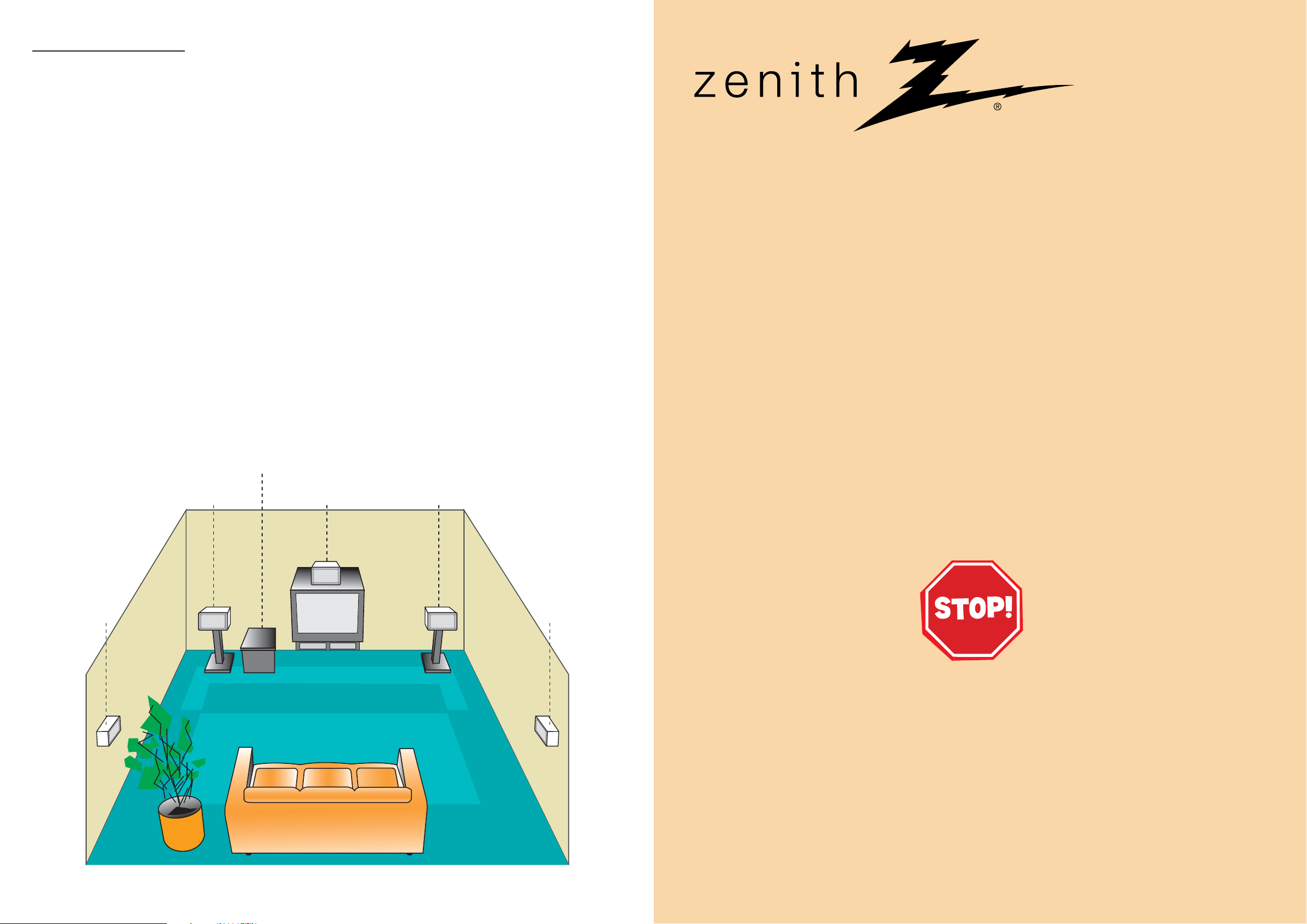
Speaker Positions
The normal setup uses 6 speakers (2 front speakers, center speaker, 2 rear speakers and subwoofer).
• Front Speakers
From your listening poition, place the speakers an equal distance away and with an interval of 45 degrees between
speakers.
• Center Speaker
It is ideal if the center speaker and front speakers at the same height. You would normally place the center speaker
above or below the television as shown below.
• Rear Speakers
Place the rear surround speakers to the left and right behind the primary listening area. These speakers recreate
sound motion and atmosphere required for surround playback. For best results, do not install the rear speakers too far
behind the listening position, install them at or above the level of the listener’s ears. It is also effective to direct the
rear speakers towards a wall or ceiling to further disperse the sound.
For smaller room sizes, if the audience is near to the rear wall, place the rear speakers opposite each other, and
24 - 36 inches above the listeners’ ears.
•Subwoofer
This can be placed in any front position.
P/N: 3840R-Q026H
Zenith Part No. 206-03920
Rear Speaker
(Left)
Front Speaker
(Left)
SUB-
WOOFER
Center
Speaker
Front Speaker
(Right)
Rear Speaker
(Right)
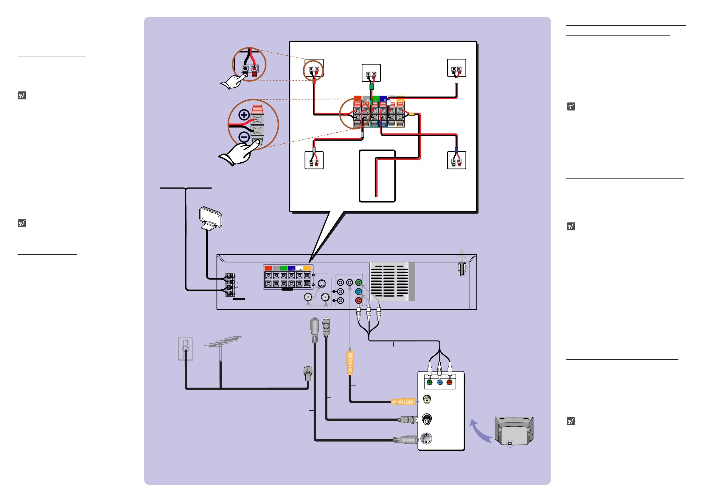
Connecting Antenna/Cable TV
to DVD+Hi-Fi VCR System
11
Disconnect the antenna leads from the rear
of the TV.
22
Identify the type of cable from your antenna. If it is a round cable as illustrated, it is
a 75 ohm coaxial antenna cable. This
cable will connect directly to the jack
marked ANTENNA/CABLE IN on your
DVD+Hi-Fi VCR System.
ip
If your antenna lead wire is a flat type antenna
cable, connect it to an Antenna Adapter (300ohm to 75-ohm) (not supplied) and slip the
Adapter onto the ANTENNA/CABLE IN jack.
The Adapter does not screw on to the
DVD+Hi-Fi VCR, it just slips over the jack.
Speaker System Connections
Connect the speakers using the supplied
speaker cords, match the colors on the cords
with the terminal colors. To obtain the best
possible surround sound, adjust the speaker
parameters (distance, level, etc.).
otes
Be sure to match the speaker cord to the
appropriate terminal on the components: 3
to 3 and # to #. If the cords are reversed,
the sound will be distorted and lack bass.
When making the sound louder, adjust the
sound level carefully to avoid excessive volume output to the speakers.
Do not disassemble the front covers of supplied
speakers.
Only 2-channel stereo (Front Left, Front Right &
Subwoofer) is available in VCR mode, thus sound
might not be heard from center or rear speakers
during VCR playback. (For further sound mode
details, please refer to page 15 of the Owner’s
manual.)
Radio Antenna Connections
Connect the supplied AM/FM antennas for
radio listening.
11
Connect the AM loop antenna to the AM
antenna connectors.
22
Connect the FM wire antenna to the FM
antenna connectors.
otes
To prevent noise pickup, keep the AM loop
antenna away from the DVD+Hi-Fi VCR
System and other components.
Be sure to fully extend the FM wire antenna.
After connecting the FM wire antenna, keep
it as horizontal as possible.
TV Connections
Make one of the following connections,
depending on the capabilities of your TV.
RF Coaxial Connection (R)
Connect the ANTENNA/CABLE OUT jack on
the DVD+Hi-Fi VCR to the antenna in jack
on the TV using the 75-ohm Coaxial Cable
provided (R).
ote
If you use this connection, tune the TV to the
DVD+Hi-Fi VCR System’s RF output channel
(CH 3 or 4).
How to set the DVD+Hi-Fi VCR’s RF output channel
While the
DVD+Hi-Fi VCR System
is turned
off,
press and hold TUNING (v/V) on the
front panel for about five seconds to change
the RF output channel (CH 03 or CH 04).
“RF 03” or “RF 04” appears in the display
window.
Video Connection (V)
Connect the MONITOR OUT jack on the
DVD+Hi-Fi VCR to the video in jack on the
TV using the supplied video cable (V).
ote
If you use this connection, set the TV’s
source selector to VIDEO.
S-Video Connection (S)
Connect the S-VIDEO OUT jack on the
DVD+Hi-Fi VCR System to the S-Video in
jack on the TV using the S-Video cable (S).
Component Video (Color Stream®)
connection
Connect the COMPONENT VIDEO OUT
jacks on the DVD+Hi-Fi VCR to the corresponding in jacks on the TV using an Y Pb
Pr cable (C).
Progressive Scan (ColorStream®pro)
Connection
If your television is high-definition or “digital ready”, you may take advantage of the
DVD+Hi-Fi VCR System’s progressive
scan output for the highest video resolution possible.
If your TV does not accept the
Progressive Scan format, the picture will
appear scrambled if you try Progressive
Scan on the DVD+Hi-Fi VCR.
Connect the COMPONENT VIDEO OUT
jacks on the DVD+Hi-Fi VCR to the corresponding in jacks on the TV using an optional Y Pb Pr cable (C).
FRONT
(R 4 )
(R 4 )
REAR
CENTER
( 4 )
REAR
(L 4 )
FRONT
(L 4 )
SUB
WOOFER
( 8 )
ANT IN
VIDEO IN
S-VIDEO IN
CATV or ANTENNA
To Wall Outlet
When you connect this system to your TV,
be sure to turn off the power and unplug
both units from the wall outlet before making
any connections.
AM Loop Antenna
FM Wire Antenna
Front Speaker
(Right)
Center
Speaker
Front Speaker
(Left)
Rear Speaker
(Right)
Rear Speaker
(Left)
Subwoofer
S
R
V
C
ANTENNA
FM
GND
AM
S-VIDEO OUT
IN
OUT
ANTENNA/CABLE
SPEAKERS
FRONT
(R 4 )
(R 4 )
REAR
CENTER
( 4 )
REAR
(L 4 )
FRONT
(L 4 )
SUB
WOOFER
( 8 )
VIDEO
MONITOR
COMPONENT
VIDEO OUT
OUT
VIDEO
Y
Pb
Pr
AUDIO
1
L
R
Y
Pb
Pr
COMPONENT VIDEO /
PROGRESSIVE SCAN INPUT
 Loading...