

Goldstar Wr-8020 Service Manual

Room Air Conditioner
SVC MANUAL(Exploded View)
MODEL : R-8000A, WR-8020, R-8000AY3
CAUTION
Before Servicing the unit, read the safety precautions in General SVC manual.
Only for authorized service personnel.
Internal Use Only
http://biz.lgservice.com

CONTENTS
1. PREFACE
1.1 SAFETY PRECAUTIONS................................2
1.2 INSULATION RESISTANCE TEST .................2
1.3 SPECIFICATIONS...........................................3
1.4 FEATURES......................................................4
1.5 CONTROL LOCATIONS .................................4
2.
DISASSEMBLY INSTRUCTIONS
2.1 MECHANICAL PARTS ....................................5
2.1.1 FRONT GRILLE .....................................5
2.1.2 CABINET ................................................5
2.1.3 CONTROL BOX .....................................5
2.2 AIR HANDLING PARTS ..................................6
2.2.1 AIR GUIDE AND BLOWER ....................6
2.2.2 FAN AND SHROUD ...............................6
2.3 ELECTRICAL PARTS......................................7
2.3.1 OVERLOAD PROTECTOR ....................7
2.3.2 COMPRESSOR......................................7
2.3.3 CAPACITOR...........................................7
2.3.4 POWER CORD ......................................8
2.3.5 THERMOSTAT.......................................8
2.3.6 ROTARY SWITCH .................................8
2.3.7 MOTOR ..................................................8
2.4 REFRIGERATION CYCLE ..............................9
2.4.1 CONDENSER.........................................9
2.4.2 EVAPORATOR.......................................9
2.4.3 CAPILLARY TUBE .................................9
3.
INSTALLATION
3.1 SELECT THE BEST LOCATION...................12
3.2 CHECK OF INSTALLATION..........................12
3.3 HOW TO DRAIN............................................12
3.4 HOW TO INSTALL ........................................13
3.5
HOW TO USE THE REVERSIBLE INLET GRILLE
4.
TROUBLESHOOTING GUIDE
4.1 OUTSIDE DIMENSIONS ...............................18
4.2 PIPING SYSTEM...........................................18
4.3 TROUBLESHOOTING GUIDE ......................19
...17
5. SCHEMATIC DIAGRAM
5.1 CIRCUIT DIAGRAM ......................................24
5.2 ELECTRONIC CONTROL DEVICE...............25
5.3 COMPONENTS LOCATION
(OF MAIN P.C.B ASM) ..................................26
5.4 COMPONENTS LOCATION
(OF DISPLAY P.C.B ASM) ............................26
6. EXPLODED VIEW ..................................27
1. PREFACE
This
SERVICE MANUAL provides various service information, including the mechanical and electrical
parts etc. This room air conditioner was manufactured and assembled under a strict quality control system.
The refrigerant is charged at the factory. Be sure to read the safety precautions prior to servicing the unit.
1.1 SAFETY PRECAUTIONS
1. When servicing the unit, set the ROTARY SWITCH
or POWER SWITCH to OFF and unplug the power
cord.
2. Observe the original lead dress.
If a short circuit is found, replace all parts which
have been overheated or damaged by the short
circuit.
3. After servicing the unit, make an insulation resistance test to protect the customer from being
exposed to shock hazards.
Copyright ©2008 LG Electronics. Inc. All right reserved.
Only for training and service purposes
1.2
INSULATION RESISTANCE TEST
1. Unplug the power cord and connect a jumper
between 2 pins (black and white).
2. The grounding conductor (green) is to be open.
3. Measure the resistance value with an ohm meter
between the jumpered lead and each exposed
metallic part on the equipment at all the positions
(except OFF) of the ROTARY SWITCH.
4. The value should be over 1MΩ.
- 2 -
LGE Internal Use Only

1.3 SPECIFICATIONS
1.3.1 FOR R-8000A
MODELS
ITEMS
POWER SUPPLY
COOLING CAPACITY (Btu/h)
INPUT (W)
RUNNING CURRENT (A)
E.E.R (BTU/W.h)
OPERATING
CONDITION
REFRIGERANT (R-22) CHARGE
EVAPORATOR
CONDENSER
FAN, INDOOR
FAN, OUTDOOR
FAN SPEEDS, FAN/COOLING
FAN MOTOR
OPERATION CONTROL
INDOOR (°C)
OUTDOOR (°C)
R-8000A WR-8020 R-8000AY3
1ø, 115, 60Hz
8,000
840 800 820
7.4 7.3 7.6
9.5 10.0 9.8
26.7(DB)*
35(DB)*
385g (13.6 Oz) 260g (9.2 Oz)
2 ROW 14 STACKS, SLIT-FIN TYPE
2 ROW 16 STACKS, LOUVERED-FIN TYPE
BLOWER TURBO
PROPELLER TYPE FAN WITH SLINGER-RING
ROTARY SWITCH
19.4(WB)**
23.9(WB)**
2/3
6 POLES
ROOM TEMP. CONTROL
AIR DIRECTION CONTROL
CONSTRUCTION
PROTECTOR
POWER CORD
DRAIN SYSTEM
NET WEIGHT (lbs/kg)
OUTSIDE DIMENSION (inch)
(W x H x D) (mm)
* DB:Dry Bulb
**
WB:Wet Bulb
COMPRESSOR
FAN MOTOR
THERMOSTAT
VERTICAL LOUVER (RIGHT & LEFT)
HORIZONTAL LOUVER (UP & DOWN)
SLIDE IN-OUT CHASSIS
OVERLOAD PROTECTOR
INTERNAL THERMAL PROTECTOR
(3 WIRE WITH GROUDING)
ATTACHMENT PLUG (CORD-CONNECTED TYPE)
DRAIN PIPE OR SPLASHED BY FAN SLINGER
64/29
181/2 x 137/8 x 2011/16
470 x 353 x 525
Copyright ©2008 LG Electronics. Inc. All right reserved.
Only for training and service purposes
- 3 -
LGE Internal Use Only

1.4 FEATURES
CLOSE VENT OPEN
• Designed for COOLING ONLY.
• Powerful and whispering cooling.
• Slide-in and slide-out chassis for the simple
installation and service.
• Side air-intake, side cooled-air discharge.
1.5 CONTROL LOCATIONS
1.5.1 COOLING ONLY MODEL
• VENTILATION
The ventilation lever must be in the CLOSE position
in order to maintain the best cooling conditions.
When a fresh air is necessary in the room, set the
ventilation lever OPEN position.
The damper is opened and room air is exhausted.
• THERMOSTAT
Thermostat will automatically control the
temperature of the room. Select a higher number for
a cooler temperature in the room. The temperature
is selected by positioning the knob to the desired
position.
The 5 or 6 position is a normal setting for average
conditions.
• Built-in adjustable THERMOSTAT
• Washable one-touch filter
• Compact size
• Reliable and efficient rotary compressor is equipped.
• OPERATION
OFF : Turns the air conditioner to off.
MED FAN : Permits the medium fan speed
operation without cooling.
LOW FAN : Permits the low fan speed operation
without cooling.
HIGH COOL : Permits cooling with the high fan speed
operation.
MED COOL : Permits cooling with the medium fan
speed operation.
LOW COOL : Permits cooling with the low fan speed
operation.
Copyright ©2008 LG Electronics. Inc. All right reserved.
Only for training and service purposes
- 4 -
LGE Internal Use Only
2. DISASSEMBLY INSTRUCTIONS
— Before the following disassembly, POWER SWITCH set to OFF and disconnect the power cord.
2.1 MECHANICAL PARTS
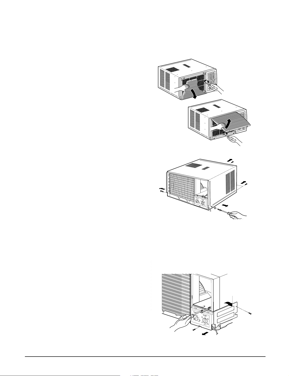
2.1.1 FRONT GRILLE
1. Open the lnlet grille upward or downward.
2. Remove the screw which fastens the front grille.
3. Pull the front grille from the right side.
4. Remove the front grille.
5. Re-install the component by referring to the
removal procedure, above.(See Figure 1)
Figure 1
2.1.2 CABINET
1. After disassembling the FRONT GRILLE, remove
the 2 screws which fasten the cabinet at both
sides.
2. Remove the 2 screws which fasten the cabinet at
back.
3. Pull the base pan forward. (See Figure 2)
4. Remove the cabinet.
5. Re-install the component by referring to the
removal procedure, above.
2.1.3 CONTROL BOX
1. Disconnect the unit from the power source.
2. Remove the front grille. (Refer to section 2.1.1)
3. Remove the cabinet. (Refer to section 2.1.2)
4. Remove the screw which fastens the control box
cover.
5. Remove the housing which connects motor wire
in the control box.
6. Remove the 3 leads from the compressor.
(Refer to section 2.3.1)
7.Discharge the capacitor by placing a 20,000
ohmresistor across the capacitor terminals.
8. Remove the 2 screws which fasten the control
box.(See Figure 3)
9. Pull the control box forward completely.
10. Re-install the components by referring to the
removal procedure, above. (See Figure 3)
(Refer to the circuit diagram found on page 24 in
this manual or on the control box.)
Figure 2
Figure 3
Copyright ©2008 LG Electronics. Inc. All right reserved.
Only for training and service purposes
- 5 -
LGE Internal Use Only
2.2 AIR HANDLING PARTS
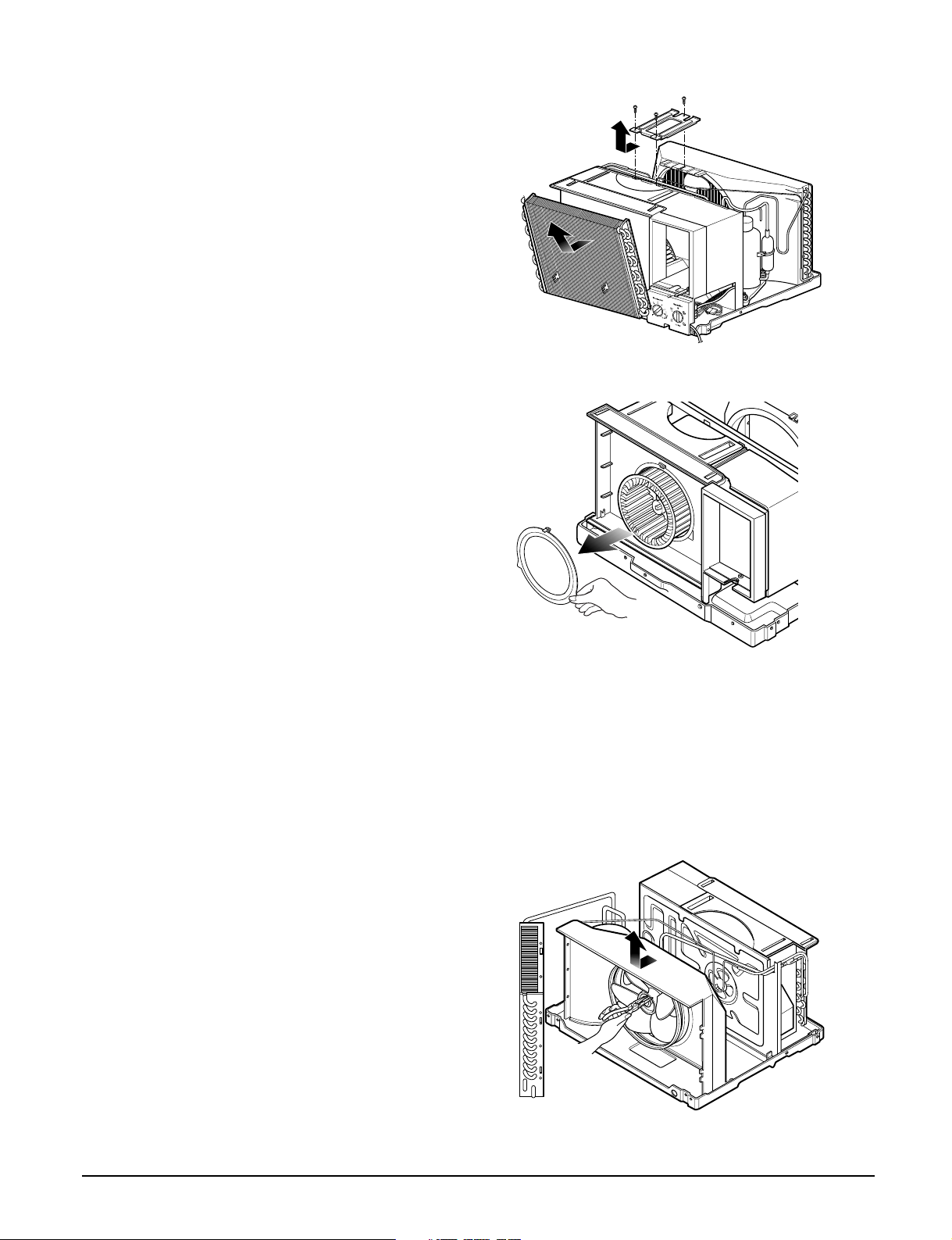
2.2.1 AIR GUIDE AND BLOWER
1. Remove the front grille. (Refer to section 2.1.1)
2. Remove the cabinet. (Refer to section 2.1.2)
3. Remove the control box. (Refer to section 2.1.3)
4. Remove the 3 screws which fasten the brace.
5. Remove the brace.
6. Remove the 2 screws which fasten the evaporator.
7. Move the evaporator forward and pulling it upward
slightly. (See Figure 4)
8. Move the evaporator to the left carefully.
9. Pull out the hook of orifice by pushing the tabs and
remove it. (See Figure 5)
10. Remove the clamp with a hand plier which
secures the blower.
11. Remove the blower.
12. Remove the 4 screws which fasten the air guide
from the barrier.
13. Move the air guide backward, pulling out from the
base pan.
14. Re-install the components by referring to the
removal procedure, above.
Figure 4
2.2.2 FAN AND SHROUD
1. Remove the cabinet. (Refer to section 2.1.2)
2. Remove the brace (Refer to section 2.2.1)
3. Remove the 3 screws which fasten the condenser.
4. Move the condenser to the left carefully.
5. Remove the clamp which secures the fan.
6. Remove the fan and then pull out the shroud.
(See Figure 6)
7. Re-install by referring to the removal procedure.
Figure 5
Copyright ©2008 LG Electronics. Inc. All right reserved.
Only for training and service purposes
- 6 -
Figure 6
LGE Internal Use Only
2.3 ELECTRICAL PARTS
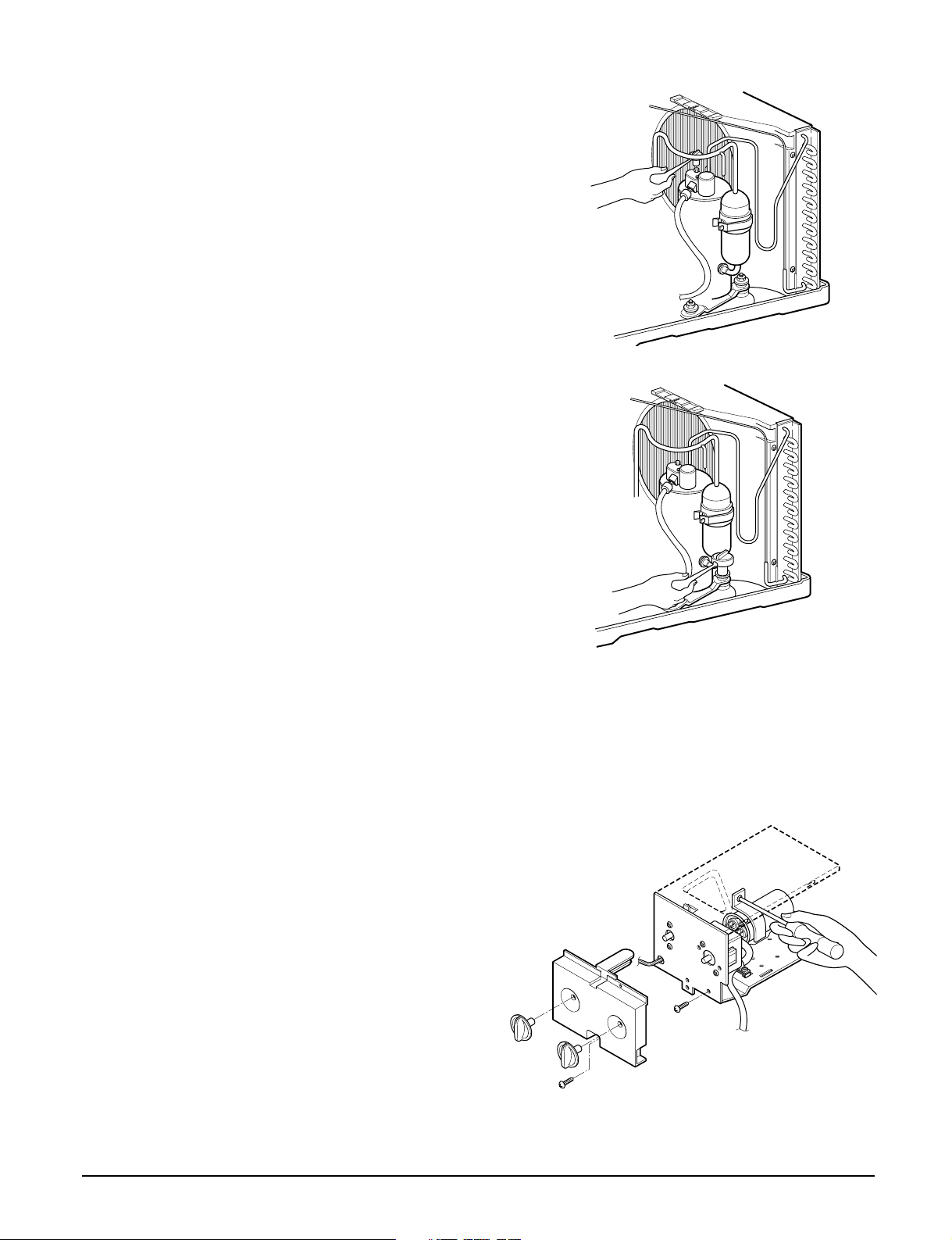
2.3.1 OVERLOAD PROTECTOR
1. Remove the cabinet. (Refer to section 2.1.2)
2. Remove the nut which fastens the terminal cover.
3. Remove the terminal cover. (See Figure 7)
4. Remove all the leads from the overload protector.
5. Remove the overload protector.
6. Re-install the component by referring to the
removal procedure, above.
2.3.2 COMPRESSOR
1. Remove the cabinet. (Refer to section 2.1.2)
2. Discharge the refrigerant system using a Freon
Recovery System.
If there is no valve to attach the recovery system,
install one (such as a WATCO A-1) before venting
the FreonTM. Leave the valve in place after
servicing the system.
3. Remove the overload protector. (Refer to section
2.3.1)
4. After purging the unit completely, unbraze the
suction and discharge tubes at the compressor
connections.
5. Remove the 3 nuts and the 3 washers which
fasten the compressor.
6. Remove the compressor. (See Figure 8)
7. Re-install the components by referring to the
removal procedure, above.
Figure 7
TM
Figure 8
2.3.3 CAPACITOR
1. Remove the control box. (Refer to section 2.1.3)
2. Remove the knobs and the screw which fasten
control panel from control box.
3. Remove the screw which located in the front.
4. Open the bottom side of control box.
5. Remove the screw and the clamp which fastens
the capacitor.
6. Disconnect all the leads of capacitor terminals.
7. Re-install the components by referring to the
removal procedure, above. (See Figure 9)
Copyright ©2008 LG Electronics. Inc. All right reserved.
Only for training and service purposes
- 7 -
Figure 9
LGE Internal Use Only
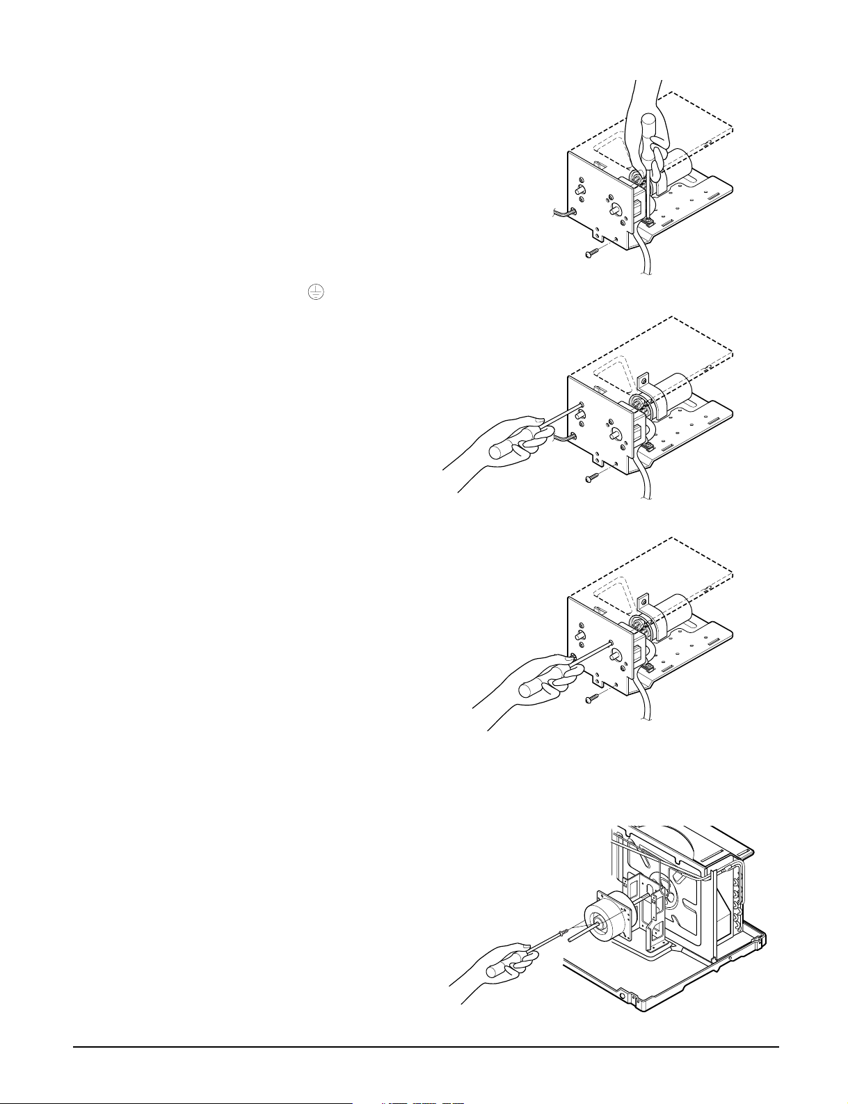
2.3.4 POWER CORD
1. Remove the control box. (Refer to section 2.1.3)
2. Open the control box. (Refer to section 2.3.3)
3. Disconnect the grounding screw from the control
box.
4. Disconnect the 2 receptacles.
5. Remove a screw which fastens the clip cord.
(See Figure 10)
6. Remove the power cord.
7. Re-install the component by referring to the above
removal procedure, above.
(Use only one ground-marked hole for ground
connection.)
8. If the supply cord of this appliance is damaged, it
must be replaced by the special cord. (The
special cord means the cord which has the same
specification marked on the supply cord attached at
the unit.)
2.3.5 THERMOSTAT
1. Remove the control box. (Refer to section 2.1.3)
2. Open the control box. (Refer to section 2.3.3)
3. Remove the 2 screws which fasten the thermostat.
4. Disconnect 2 leads of thermostat terminals.
5. Remove the thermostat.
6. Re-install the components by refereing to the above
removal procedure. (See Figure 11)
Figure 10
Figure 11
2.3.6 ROTARY SWITCH
1. Remove the control box. (Refer to section 2.1.3)
2. Open the control box. (Refer to section 2.3.3)
3. Remove the 2 screws which fasten the rotary switch.
4. Disconnect all the leads of the rotary switch terminals.
5. Remove the rotary switch.
6. Re-install the components by referring to the above
removal procedure. (See Figure 12)
2.3.7 MOTOR
1. Remove the cabinet. (Refer to section 2.1.2)
2. Remove the evaporator. (Refer to section 2.2.1)
3. Remove the orifice. (Refer to section 2.2.1)
4. Remove the blower. (Refer to section 2.2.1)
5. Remove the fan. (Refer to section 2.2.2)
6. Remove the control box cover and housing of the
motor in the control box. (Refer to section 2.1.3)
7. Remove the 2 screws which fasten the motor from
the mount motor. (See Figure 13)
8. Remove the motor.
9. Re-install the components by referring to the
removal procedure, above.(See Figure 13)
Figure 12
Figure 13
Copyright ©2008 LG Electronics. Inc. All right reserved.
Only for training and service purposes
- 8 -
LGE Internal Use Only

2.4 REFRIGERATING CYCLE
CAUTION
Discharge the refrigerant system using a
FreonTMRecovery System.
If there is no valve to attach the recovery
system, install one (such as a WATCO A-1)
before venting the FreonTM. Leave the valve in
place after servicing the system.
2.4.1 CONDENSER
1. Remove the cabinet. (Refer to section 2.1.2)
2. Remove the 3 screws which fasten the
brace.(Refer to section 2.2.1)
3. Remove the 3 screws which fasten the condenser
and shroud.
4. After discharging the refrigerant completely,
unbraze the interconnecting tube at the condenser
connections.
5. Remove the condenser carefully.
6. Re-install the component by referring to notes.
(See Figure 14)
Figure 14
2.4.2 EVAPORATOR
1. Remove the cabinet. (Refer to section 2.1.2)
2. Remove the 2 screws which fasten the evaporator.
3. Move the evaporator sideways carefully.
(Refer to section 2.2.1)
4. After discharging the refrigerant completely,
unbraze the interconnecting tube at the evaporator
connections.
5. Remove the evaporator carefully.
6. Re-install the component by referring to notes.
(See Figure 15)
2.4.3 CAPILLARY TUBE
1. Remove the cabinet. (Refer to section 2.1.2)
2. After discharging the refrigerant completely,
unbraze the interconnecting tube at the capillary
tube.(See caution above)
3. Remove the capillary tube.
4. Re-install the component by referring to notes.
Figure 15
Copyright ©2008 LG Electronics. Inc. All right reserved.
Only for training and service purposes
- 9 -
LGE Internal Use Only
 Loading...