

Goldstar Hblg2400r, Hblg2350e, Hblg1800r, Wg2400r, Wg1800r Service Manual

Room Air Conditioner
SVC MANUAL(Exploded View)
CAUTION
Before Servicing the unit, read the safety precautions in General SVC manual.
Only for authorized service personnel.
Internal Use Only
http://biz.lgservice.com
MODEL :
LWM1836TAS, LWM1836QCG, LWN2131QAG, Y5USC24-6R,
WG2400R, LWN2432QAS, LWN2433TCS, WG1800R, M1804R,
Y5USC18-6R, LWM1836QAS, HBLG1800R, HBLG2400R,
M2403R, LWC243NSMM0, LWC243NSMM2, HBLG2350E

CONTENTS
1. PREFACE
1.1 SAFETY PRECAUTIONS................................................................................................................................3
1.2 INSULATION RESISTANCE TEST.................................................................................................................3
1.3 SPECIFICATIONS...........................................................................................................................................3
1.4 FEATURES .....................................................................................................................................................4
1.5 CONTROL LOCATIONS .................................................................................................................................4
2.
DISASSEMBLY INSTRUCTIONS
2.1 MECHANICAL PARTS....................................................................................................................................5
2.1.1 FRONT GRILLE .....................................................................................................................................5
2.1.2 CABINET................................................................................................................................................5
2.1.3 CONTROL BOX .....................................................................................................................................5
2.2 AIR HANDLING PARTS..................................................................................................................................6
2.2.1 COVER (AT THE TOP) ..........................................................................................................................6
2.2.2 BLOWER................................................................................................................................................6
2.2.3 FAN ........................................................................................................................................................6
2.2.4 SHROUD................................................................................................................................................7
2.3 ELECTRICAL PARTS .....................................................................................................................................7
2.3.1 MOTOR ..................................................................................................................................................7
2.3.2 COMPRESSOR .....................................................................................................................................7
2.3.3 CAPACITOR ..........................................................................................................................................7
2.3.4 POWER CORD ......................................................................................................................................8
2.3.5 THERMISTOR........................................................................................................................................8
2.3.6 SYNCHRONOUS MOTOR.....................................................................................................................8
2.4 REFRIGERATION CYCLE..............................................................................................................................9
2.4.1 CONDENSER ........................................................................................................................................9
2.4.2 EVAPORATOR ......................................................................................................................................9
2.4.3 CAPILLARY TUBE .................................................................................................................................9
3.
INSTALLATION
3.1 HOW TO INSTALL THE UNIT.......................................................................................................................12
3.2
HOW TO USE THE REVERSIBLE INLET GRILLE
3.3 WINDOW REQUIREMENTS.........................................................................................................................13
3.4 INSTALLATION KITS CONTENTS ...............................................................................................................13
3.5 SUGGESTED TOOL REQUIREMENTS .......................................................................................................14
3.6 CABINET INSTALLATION ............................................................................................................................15
4.
TROUBLESHOOTING GUIDE
4.1 OUTSIDE DIMENSIONS...............................................................................................................................17
4.2 PIPING SYSTEM...........................................................................................................................................17
4.3 TROUBLESHOOTING GUIDE ......................................................................................................................18
..................................................................................................................
12
5. SCHEMATIC DIAGRAM
5.1 CIRCUIT DIAGRAM ......................................................................................................................................27
5.2 ELECTRONIC CONTROL DEVICE ..............................................................................................................28
5.3
COMPONENTS LOCATION(FOR MAIN P.C.B ASM
5.4
COMPONENTS LOCATION(FOR DISPLAY P.C.B ASM)
) .......................................................................................................29
.......................................................................................................29
6. EXPLODED VIEW..................................................................................................................................30
Copyright ©2007 LG Electronics. Inc. All right reserved.
Only for training and service purposes
- 2 -
LGE Internal Use Only

1. PREFACE
This service manual provides various service information, including the mechanical and electrical parts, etc.
This room air conditioner was manufactured and assembled under a strict quality control system.
The refrigerant is charged at the factory. Be sure to read the safety precautions prior to servicing the unit.
1.1 SAFETY PRECAUTIONS
1. When servicing, set the POWER of CONTROL
BOARD to Off and unplug the power cord.
2. Observe the original lead dress.
If a short circuit is found, replace all parts which
have been overheated or damaged by the short
circuit.
3. After servicing, make an insulation resistance test to
prevent the customer's exposure to shock
hazards.
1.3 SPECIFICATIONS
MODELS
ITEMS
POWER SUPPLY
COOLING CAPACITY (Btu/h)
INPUT (W)
RUNNING CURRENT (A)
REFRIGERANT CHARGE (g)
OPERATING INDOOR (°C)
TEMPERATURE OUTDOOR (°C)
FAN, INDOOR
FAN, OUTDOOR
FAN SPEEDS, FAN/COOLING
FAN MOTOR
OPERATION CONTROL
ROOM TEMP. CONTROL
AIR DIRECTION CONTROL
CONSTRUCTION
PROTECTOR COMPRESSOR
FAN MOTOR
POWER CORD
DRAIN SYSTEM
NET WEIGHT (lbs/kg)
OUTSIDE DIMENSION
(W x H x D) (mm)
(inch)
17,500/18,000 17,500 18,000 21,000 23,500/24,000 24,000 24,000 23,000 23,000/23.500
M1804R
WG1800R
HBLG1800R
1,800/1,850 1,840 1,050 2,470 2,760/2,820 2,820 2,420 2,540 2,450/2,500
9.0/8.3 8.5 8.3 10.3 13.7/12.7 12.7/12.9 11.2 11.5 12.2/11.3
LWM1836TASL
WN1836QCG
1Ø, 208/230V, 60Hz
710(25.1 OZ) 995(35.1 OZ)/980(34.6 OZ) 880(31 OZ) 985(34.7 OZ)
120/54 143/65
27
26 x 16
/32 x 269/16 26 x 1627/32 x 305/16
660 x 428 x 675 660 x 428 x 770
LWM1863QAS
Y5USC18-6R
1Ø, 220V, 60Hz 1Ø, 220V, 60Hz
1.2
INSULATION RESISTANCE TEST
1. Unplug the power cord and connect a jumper
between 2 pins (black and white).
2. The grounding conductor (green or green and
yellow) is to be open.
3. Measure the resistance value with an ohm meter
between the jumpered lead and each exposed
metallic part on the equipment at all Mode [except
POWER OFF].
4. The value should be over 1 MΩ.
WG2400R
LWN2131QAG
BLOWER TURBO
PROPELLER TYPE FAN WITH SLINGER-RING
VERTICAL LOUVER(RIGHT & LEFT)
HORIZONTAL LOUVER(UP & DOWN)
INTERNAL OVERLOAD PROTECTOR
INTERNAL THERMAL PROTECTOR
1.6m (3 WIRE WITH GROUNDING)
ATTACHMENT PLUG(CORD-CONNECTED TYPE)
DRAIN PIPE OR SPLASHED BY FAN SLINGER
HBLG2400R
M2403R
1Ø, 208/230V, 60Hz
26.7(DB) 19.4(WB)
35(DB) 23.9(WB)
6 POLES
TOUCH PANEL
THERMISTOR
SLIDE IN-OUT CHASSIS
LWN2432QAS
Y5USC24-6R
LWC243NSMM0
1Ø, 220V, 60Hz 1Ø, 208/230V, 60Hz
3/3
LWN2433TCS LWC243NSMM2 HBLG2350E
* DB:Dry Bulb
NOTE : Specifications are subject to minor change without notice for further improvement.
Copyright ©2007 LG Electronics. Inc. All right reserved.
Only for training and service purposes
**
WB:Wet Bulb
- 3 -
LGE Internal Use Only
1.4 FEATURES
Part A
Part B
VENTCLOSE OPEN
2
3
1
4
5 7
Powe r
Temp
Fan Speed
Timer Mode
Energy
Saver
Auto
Swing
1
4
3
6
2
7
5
6
6
• Designed for cooling only.
• Powerful and quiet cooling.
• Slide-in and slide-out chassis for the simple installation
and service.
• Reversible inlet grille.
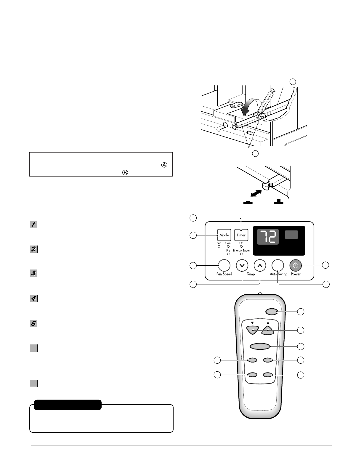
1.5 CONTROL LOCATIONS
• VENTILATION
The ventilation lever must be in the CLOSE position in
order to maintain the best cooling conditions.
When a fresh air is necessary in the room, set the
ventilation lever to the OPEN position.
The damper is opened and room air is exhausted.
NOTE: Before using the ventilation feature, make
the lever, as shown. First, pull down part
to horizontal line with part .
Precaution: The Remote Control unit will not function
properly if strong light strikes the sensor
window of the air conditioner or if there
are obstacles between the Remote
Control unit and the air conditioner.
• Side air-intake, side cooled-air discharge.
• Built in adjustable THERMISTOR.
• Washable one-touch filter.
• Compact size.
POWER BUTTON
Operation starts, when this button is pressed and stops
when you press the button again.
OPERATION MODE SELECTION BUTTON
Select Cooling, or Fan or Dehumidification(Dry) mode
with button. (Dry mode is not to all models.)
ON/OFF TIMER BUTTON
Set the time of starting and stopping operation. The
timer is set by 1 hour.
FAN SPEED SELECTOR
Select the fan speed in three steps.
- High [F3] ➔ Low[F1] ➔ Med[F2]➔ High[F3]... .
ROOM TEMPERATURE SETTING BUTTON
Control the room temperature within a range of 60°F to
86°F by 1°F.
ENERGY SAVER
The fan stops when the compressor stops cooling.
Approximately every 3 minutes the fan will turn on and
check the room air to determine if cooling is needed.
7
AUTO SWING
7
Control the horizontal air direction by air swing system.
AUTO RESTART
In case the power comes on again after a power failure,
the unit runs as previous setting operation.
in some models)
(Available In some models)
(Available
Copyright ©2007 LG Electronics. Inc. All right reserved.
Only for training and service purposes
- 4 -
LGE Internal Use Only
2. DISASSEMBLY INSTRUCTIONS
— Before the following disassembly, POWER SWITCH is set to OFF and disconnected the power cord.
2.1 MECHANICAL PARTS
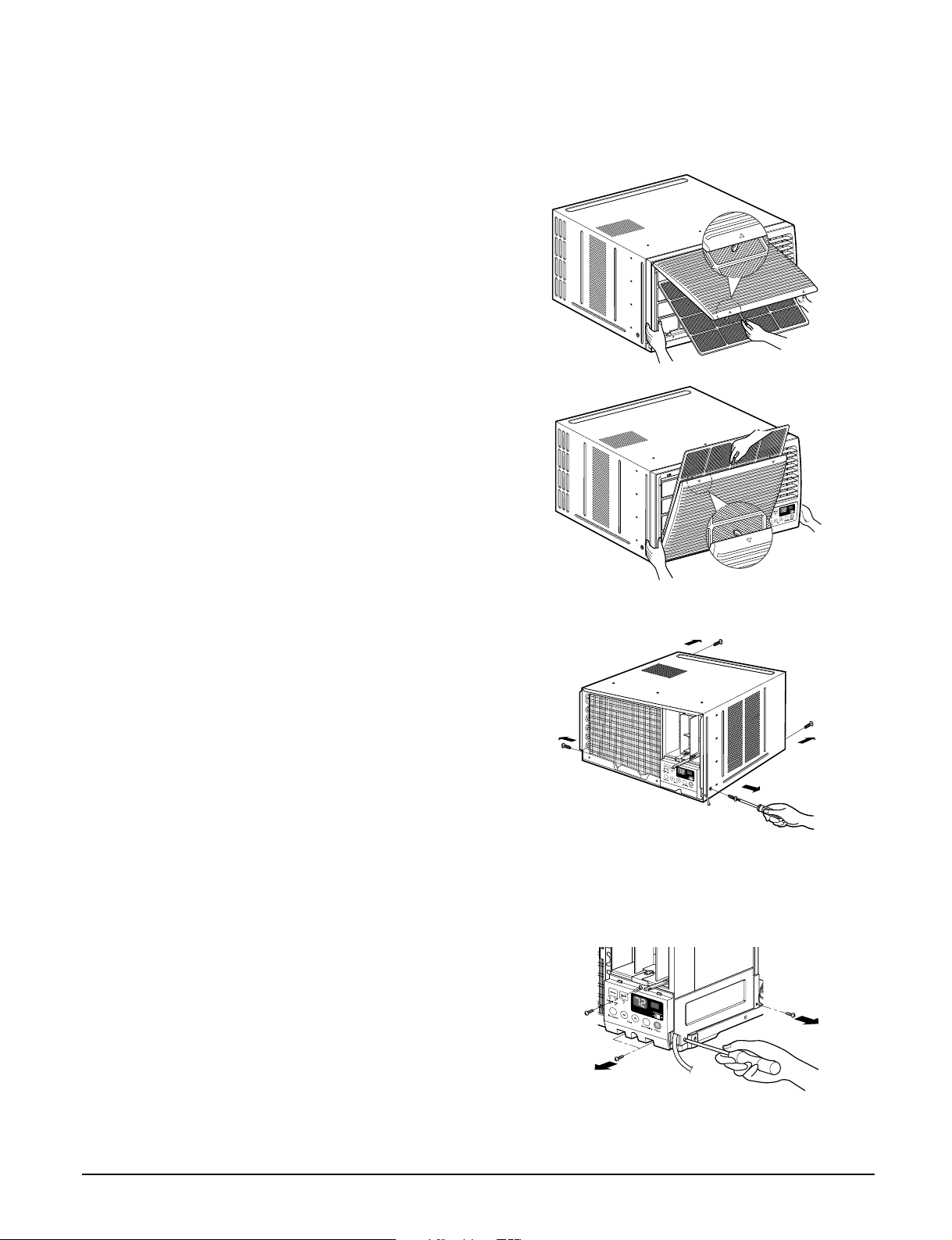
2.1.1 FRONT GRILLE
1. Open the inlet grille upward or downward.
2. Remove the screw which fastens the front grille.
3. Pull the front grille from the right side.
4. Remove the front grille. (See Fig. 1)
5. Re-install the component by referring to the
removal procedure.
NOTE: Mark ∆ of inlet grille means opening direction.
2.1.2 CABINET
1. After disassembling the FRONT GRILLE, remove
the screws which fasten the cabinet at both sides.
Keep these for later use.
2. Remove the two screws which fasten the cabinet
at back. (See Fig. 2)
3. Pull the base pan forward.
2.1.3 CONTROL BOX
1. Remove the front grille. (Refer to section 2.1.1)
2. Pull the base pan forward so that you can remove
the 2 screws which fasten the cover control at the
right side. (See Fig. 3)
3. Remove the 3 screws which fasten the control
box. (See Fig. 3)
4. Discharge the capacitor by placing a 20,000 ohm
resistor across the capacitor terminals.
5. Disconnect two wire housings in the control box.
6. Pull the control box forward completely.
7. Re-install the components by referring to the
removal procedure. (See Fig. 3)
(Refer to the circuit diagram found on page 24 in
this manual and on the control box.)
Figure 1
Figure 2
Figure 3
Copyright ©2007 LG Electronics. Inc. All right reserved.
Only for training and service purposes
- 5 -
LGE Internal Use Only

2.2 AIR HANDLING PARTS
2.2.1 COVER (AT THE TOP)
1. Remove the front grille. (Refer to section 2.1.1)
2. Remove the cabinet. (Refer to section 2.1.2)
3. Remove 11 screws which fasten the brace and
covers.
4. Remove the covers and the brace. (See Fig. 4)
5. Re-install the components by referring to the
removal procedure, above.
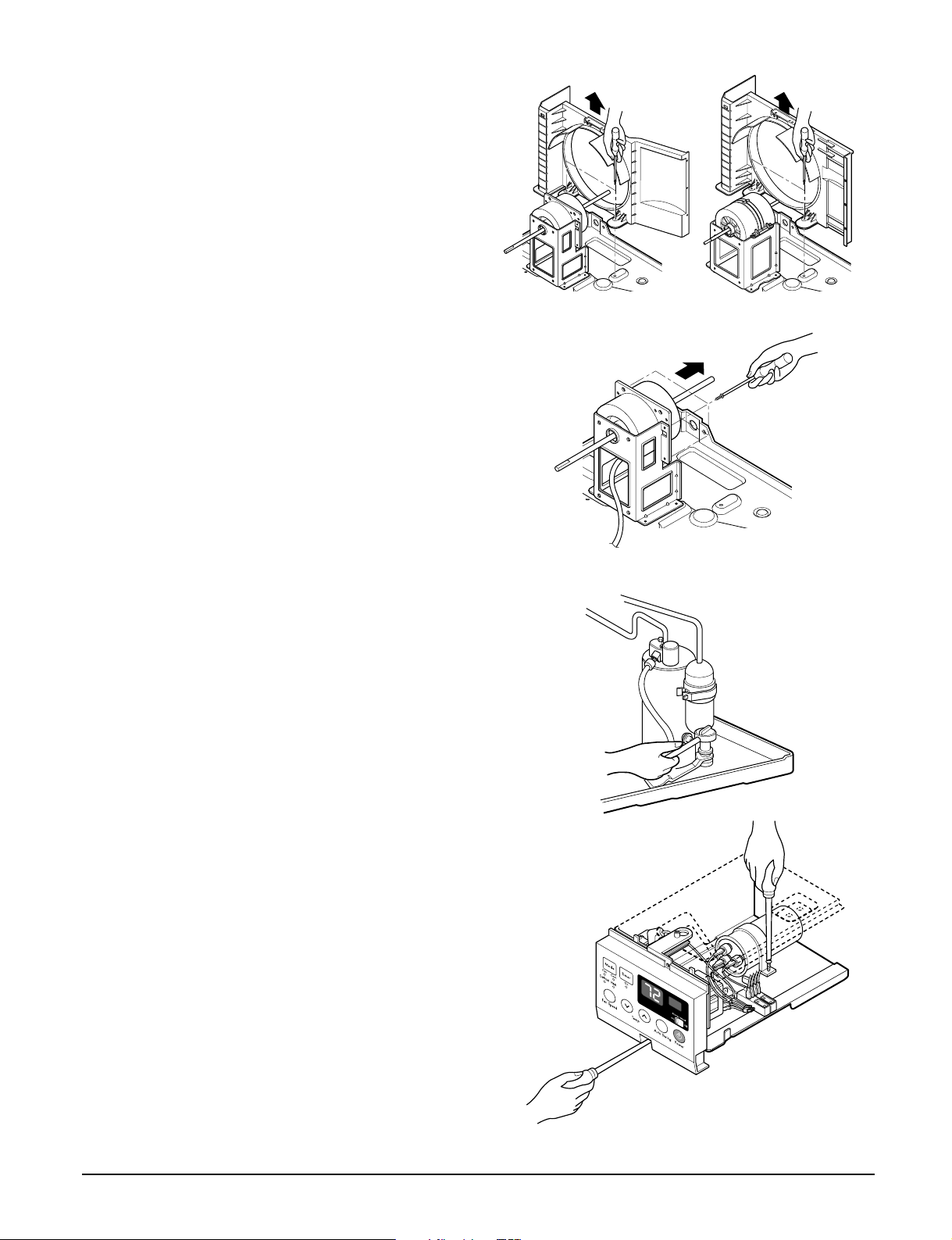
2.2.2 BLOWER
1. Remove the cover. (Refer to section 2.2.1)
2. Remove the 3 screws which fasten the
evaporator at the left side and the top side.
(See Fig. 4)
3. Move the evaporator sideward carefully.
4. Remove the orifice from the air guide carefully.
5. Remove the clamp spring which is clamped to the
boss of blower by hand plier. (See Fig. 5)
6. Pull the blower outward, without touching blades.
(See Fig. 6)
7. Re-install the components by referring to the
removal procedure, above.
Figure 4 (a) Figure 4 (b)
Figure 5
2.2.3 FAN
1. Remove the cabinet. (Refer to section 2.1.2)
2. Remove the brace and shroud cover.
(Refer to section 2.2.1)
3. Remove the 5 screws which fasten the condenser.
4. Move the condenser sideways carefully.
5. Remove the clamp which secures the fan.
6. Remove the fan. (See Fig. 7)
7. Re-install the components by referring to the
removal procedure, above.
Copyright ©2007 LG Electronics. Inc. All right reserved.
Only for training and service purposes
Figure 6
Figure 7 (a) Figure 7 (b)
- 6 -
LGE Internal Use Only
2.2.4 SHROUD
1. Remove the fan. (Refer to section 2.2.3)
2. Remove the 2 screws which fasten the shroud.
3. Remove the shroud. (See Fig. 8)
4. Re-install the component by referring to the
removal procedure, above.
2.3 ELECTRICAL PARTS
2.3.1 MOTOR
1. Remove the cabinet. (Refer to section 2.1.2)
2. Remove the cover control and disconnect a wire
housing in control box. (Refer to section 2.1.3)
3. Remove the blower. (Refer to section 2.2.2)
4. Remove the fan. (Refer to section 2.2.3)
5. Remove the 4 screws which fasten the motor.
(See Fig. 9)
6. Remove the motor.
7. Re-install the components by referring to the
removal procedure, above.
2.3.2 COMPRESSOR
1. Remove the cabinet. (Refer to section 2.1.2)
2. Discharge the refrigerant by using a Refrigerant
Recovery System.
3. Disconnect the 3 leads from the compressor.
4. After purging the unit completely, unbraze the
suction and discharge tubes at the compressor
connections.
5. Remove the 3 nuts and the 3 washers which
fasten the compressor. (See Fig. 10)
6. Remove the compressor.
7. Re-instill the components by referring to the
removal procedure, above.
Figure 8 (a) Figure 8 (b)
Figure 9
2.3.3 CAPACITOR
1. Remove the control box. (Refer to section 2.1.3)
2. Remove the screw which fasten the display panel.
3. Disconnect the 2 leads from the rocker switch and
remove the panel.
4. Remove a screw and unfold the control box.
(See Fig. 11)
5. Remove the screw and the clamp which fastens
the capacitor. (See Fig. 11)
6. Disconnect all the leads of capacitor terminals.
7. Re-install the components by referring to the
removal procedure, above.
Copyright ©2007 LG Electronics. Inc. All right reserved.
Only for training and service purposes
- 7 -
Figure 10
Figure 11
LGE Internal Use Only
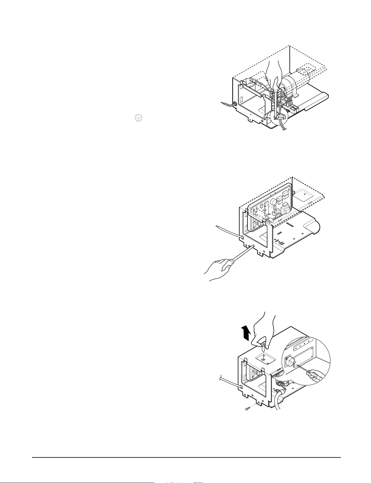
2.3.4 POWER CORD
1. Remove the control box. (Refer to section 2.1.3)
2. Unfold the control box. (Refer to section 2.3.3)
3. Disconnect the grounding screw from the control
box.
4. Disconnect 2 receptacles.
5. Remove a screw which fastens the clip cord.
6. Pull the power cord. (See Fig. 12)
7. Re-install the component by referring to the
removal procedure, above.
(Use only one ground-marked hole for ground
connection.)
8. If the supply cord of this appliance is damaged, it
must be replaced by the special cord.
(The special cord means the cord which has the
same specification marked on the supply cord
fitted to the unit.)
2.3.5 THERMISTOR
1. Remove the control box. (Refer to section 2.1.3)
2. Unfold the control box. (Refer to section 2.3.3)
3. Disconnect the thermistor terminals from main
P.W.B assembly.
4. Remove the thermistor.
5. Re-install the components by referring to the
removal procedure above. (See Figure 13)
Figure 12
2.3.6 SYNCHRONOUS MOTOR
1. Remove the control box. (Refer to section 2.1.3)
2. Unfold the control box. (Refer to section 2.3.3)
3. Remove the crankshaft.
4. Disconnect all the leads of the synchronous
motor.
5. Remove the 2 screws which fasten the
synchronous motor. (See Fig. 14)
6. Re-install the components by referring to the
removal procedure, above.
Copyright ©2007 LG Electronics. Inc. All right reserved.
Only for training and service purposes
- 8 -
Figure 13
Figure 14
LGE Internal Use Only

2.4 REFRIGERATION CYCLE
CAUTION
Discharge the refrigerant system using Freon
Recovery System.
If there is no valve to attach the recovery system,
install one (such as a WATCO A-1) before
TM
venting the Freon
after servicing the system.
. Leave the valve in place
TM
2.4.1 CONDENSER
1. Remove the cabinet. (Refer to section 2.1.2)
2. Remove the brace and the shroud cover.
(Refer to section 2.2.1)
3. Remove the 5 screws which fasten the condenser.
4. After discharging the refrigerant completely,
unbraze the interconnecting tube at the condenser
connections.
5. Remove the condenser.
6. Re-install the components by referring to notes.
(See Fig. 15)
2.4.2 EVAPORATOR
1. Remove the cabinet. (Refer to section 2.1.2)
2. Remove the top cover and the brace.
(Refer to section 2.2.1)
3. Discharge the refrigerant completely.
4. Remove the 3 screws which fasten the evaporator
at the left side and the top side.
5. Move the evaporator sideward carefully and then
unbraze the interconnecting tube at the evaporator
connectors.
6. Remove the evaporator.
7. Re-install the components by referring to notes.
(See Fig. 16)
Figure 15 (a)
Figure 15 (b)
2.4.3 CAPILLARY TUBE
1. Remove the cabinet. (Refer to section 2.1.2)
2. Remove the brace. (Refer to section 2.2.1)
3. After discharging the refrigerant completely,
unbraze the interconnecting tube at the capillary
tube.
4. Remove the capillary tube.
5. Re-install the components by referring to notes.
Copyright ©2007 LG Electronics. Inc. All right reserved.
Only for training and service purposes
- 9 -
Figure 16
LGE Internal Use Only
NOTES
— Replacement of the refrigeration cycle.
1. When replacing the refrigeration cycle, be sure to
discharge the refrigerant system using a Freon
TM
recovery System.
If there is no valve to attach the recovery system,
install one (such as a WATCO A-1) before venting
the FreonTM. Leave the valve in place after
servicing the system.
2. After discharging the unit completely, remove the
desired component, and unbrace the pinch-off
tubes.
3. Solder service valves into the pinch-off tube ports,
leaving the valves open.
4. Solder the pinch-off tubes with Service valves.
5. Evacuate as follows.
1) Connect the vacuum pump, as illustrated Fig.
17A.
2) Start the vacuum pump, slowly open manifold
valves A and B with two full turns
counterclockwise and leave the valves closed.
The vacuum pump is now pulling through valves
A and B up to valve C by means of the manifold
and entire system.
CAUTION
If high vacuum equipment is used, just crack
valves A and B for a few minutes, then open
slowly with the two full turns counterclockwise.
This will keep oil from foaming and being
drawn into the vacuum pump.
3) Operate the vacuum pump for 20 to 30 minutes,
until 600 microns of vacuum is obtained. Close
valves A and B, and observe vacuum gauge for
a few minutes. A rise in pressure would
indicate a possible leak or moisture remaining in
the system. With valves A and B closed, stop
the vacuum pump.
4) Remove the hose from the vacuum pump and
place it on the charging cylinder. See Fig. 17B.
Open valve C.
Discharge the line at the manifold connection.
5) The system is now ready for final charging.
6. Recharge as follows :
1) Refrigeration cycle systems are charged from the
High-side. If the total charge cannot be put
in the High-side, the balance will be put in the
suction line through the access valve which you
installed as the system was opened.
2)
Connect the charging cylinder as shown in Fig. 17B.
With valve C open, discharge the hose at the
manifold connection.
3) Open valve A and allow the proper charge to
enter the system. Valve B is still closed.
4) If more charge is required, the high-side will not
take it. Close valve A.
5) With the unit running, open valve B and add the
balance of the charge.
a. Do not add the liquid refrigerant to the Low-
side.
b. Watch the Low-side gauge; allow pressure to
rise to 30 lbs.
c. Turn off valve B and allow pressure to drop.
d. Repeat steps B and C until the balance of the
charge is in the system.
6) When satisfied the unit is operating correctly,
use the pinch-off tool with the unit still running
and clamp on to the pinch-off tube. Using a tube
cutter, cut the pinch-off tube about 2 inches from
the pinch-off tool. Use sil-fos solder and solder
pinch-off tube closed. Turn off the unit, allow it to
set for a while, and then test the leakage of the
pinch-off connection.
Copyright ©2007 LG Electronics. Inc. All right reserved.
Only for training and service purposes
- 10 -
LGE Internal Use Only
 Loading...