

Page 1
R OOM AIR CONDITIONER
SERVICE MANUAL
CAUTION
• BEFORE SERVICING THE UNIT, READ THE SAFETY PRECAUTIONS
IN THIS MANUAL.
• ONLY FOR AUTHORIZED SERVICE PERSONNEL.
MODEL: BG8000ER, WG8005R,
WG1005R, WG1205R
website http://www.lgservice.com
Page 2

2 Room Air Conditioner
Air Conditioner Service Manual
TABLE OF CONTENTS
Safety Precautions..........................................................................................................................................3
Dimensions .....................................................................................................................................................6
Outside Dimensions...................................................................................................................................6
Product Specifications ..................................................................................................................................7
Installation.......................................................................................................................................................8
Select the Best Location ............................................................................................................................8
Installation Check.......................................................................................................................................8
How to Secure the Drain Pipe....................................................................................................................8
How to Install..............................................................................................................................................9
Operation ......................................................................................................................................................13
Location and Function of Controls ...........................................................................................................13
Remote Control Operations ....................................................................................................................14
Disassembly ..................................................................................................................................................15
Mechanical Parts......................................................................................................................................15
Air Handling Parts ...................................................................................................................................16
Electrical Parts .........................................................................................................................................17
Refrigerating Cycle...................................................................................................................................19
Schematic Diagram.......................................................................................................................................22
Wiring Diagram.........................................................................................................................................22
Electronic Control Device.........................................................................................................................24
Components Location(For Main P.W.B ASM)...........................................................................................25
Troubleshooting Guide.................................................................................................................................26
Piping System ........................................................................................................................................26
Troubleshooting Guide .............................................................................................................................27
Exploded View ..............................................................................................................................................35
Replacement Parts List ................................................................................................................................36
Page 3
Safety Precautions
CAUTION
Safety Precautions
To prevent injury to the user or other people and property damage, the following instructions
must be followed.
Incorrect operation due to ignoring instructions will cause harm or damage. The seriousness
is classified by the following indications.
WARNING
Meanings of symbols used in this manual are as shown below.
This symbol indicates the possibility of death or serious injury.
This symbol indicates the possibility of injury or damage to property only.
Be sure not to do.
Be sure to follow the instruction.
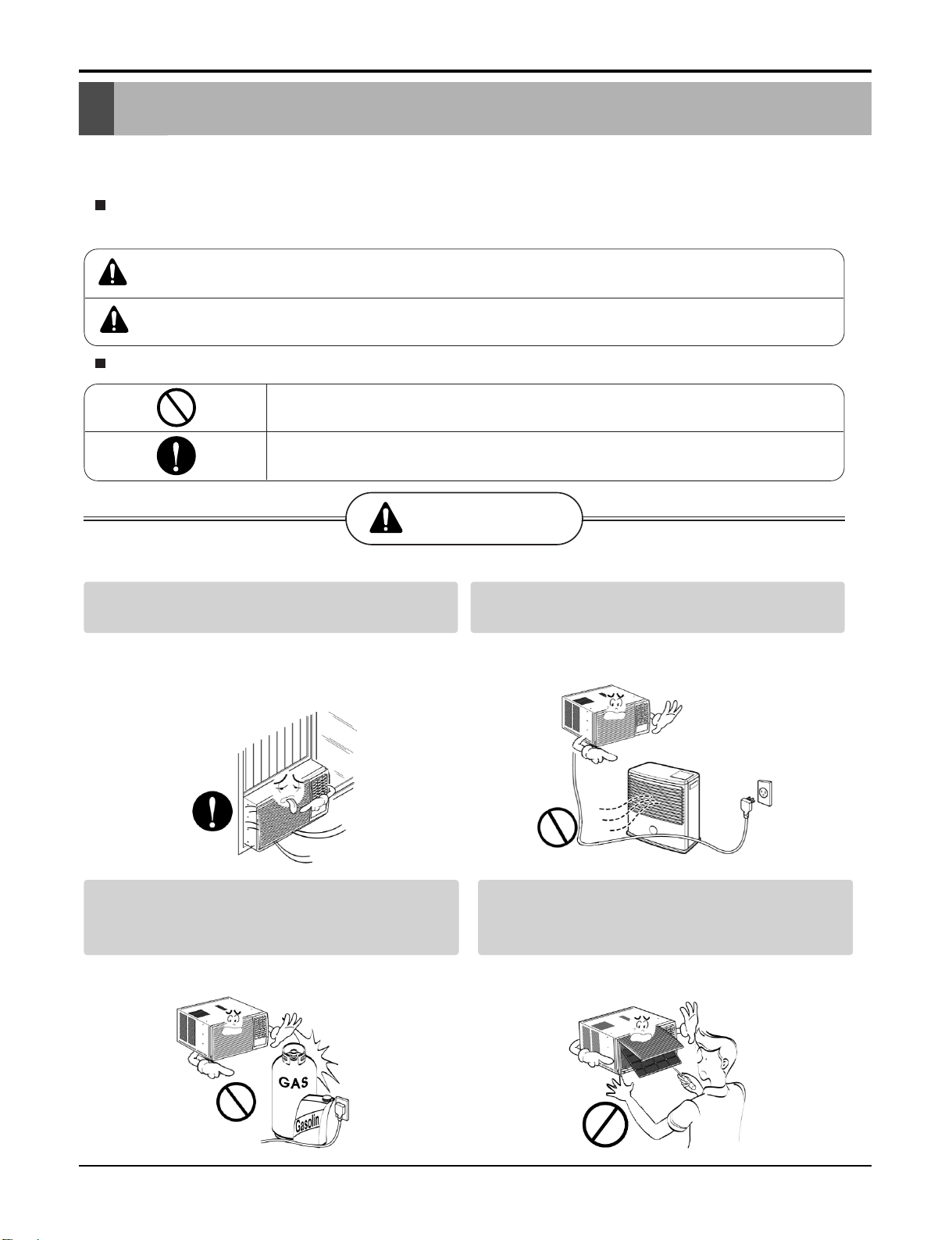
WARNING
Always install the expansion panel(s).
• Improper assembly or installation may cause
incorrect operation, including injury, fire, and
electric shock hazards.
Do not place the power cord near a heater.
• It may cause fire and electric shock.
Do not use the power cord near flammable
gas or combustibles such as gasoline,
benzene, thinner, etc.
• It may cause explosion or fire.
Do not disassemble or modify products.
• It may cause failure and electric shock.
Service Manual 3
Page 4
Safety Precautions
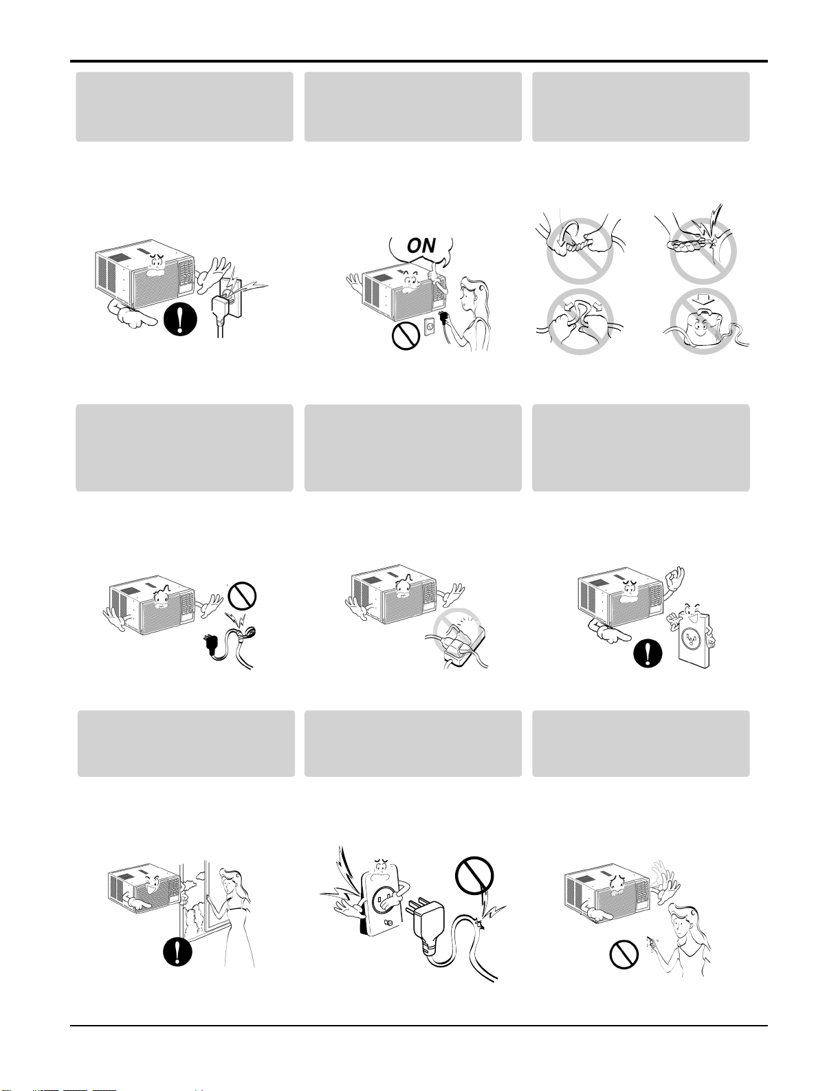
Plug in the power plug
properly.
• Otherwise, it will cause
electric shock or fire.
Do not modify power corDo not modify poDo not modify po dwer cor
Do not modify po
length.
Do not operate or stop the
unit by inserting or pulling
out the power plug.
• It will cause electric shock or
fire.
Use the air conditioner on a
single outlet circuit.(see page 7.)
Do not share the outlet with
other appliances.
Do not damage or use an
unspecified power cord.
• It will cause electric shock or
fire.
Always plug into a
grounded outlet.
• •• It will cause electr ic shoc• k or
fire.
Ventilate before operating air
conditionerwhen gas goes
out.
It may cause explosion, fire,
and burn.
•
It will cause electric shock or
fire.
Do not use the socket if it is
loose or damaged.
•• It may cause fire and electric
shock.
• No •• grounding • may cause
electric shock.
Do not operate with wet
hands or in damp
environment.
• It will cause electric shock.
4 Room Air Conditioner
Page 5
Service Manual 5
Safety Precautions
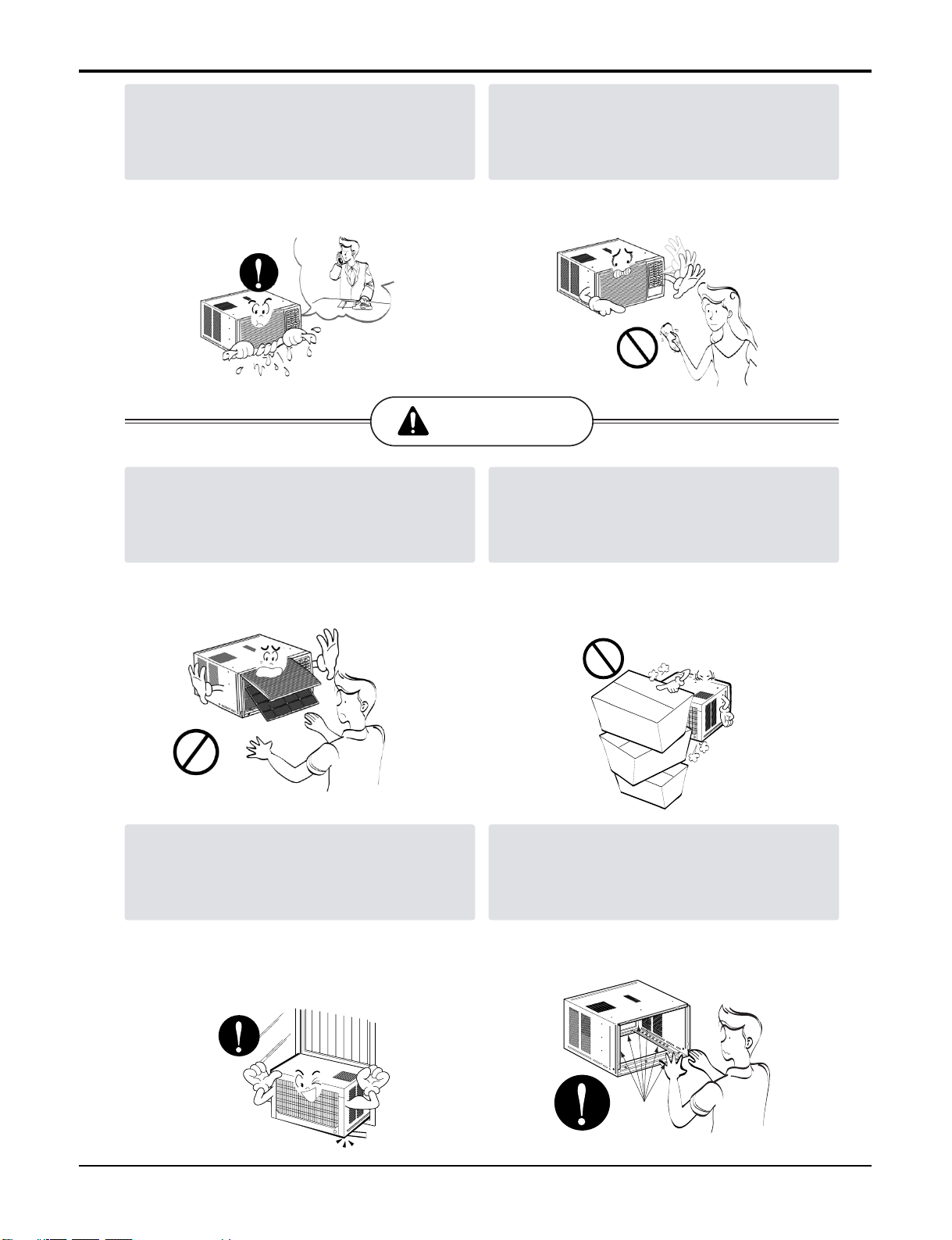
If water enters the product, turn off the the
power switch of the main body of appliance.
Contact service center after taking the powerplug out from the socket.
• It will cause electric shock or failure of
machine.
CAUTION
Never touch the metal parts of the unit
when removing the filter.
Do not clean the air conditioner with water.
• Water may enter the unit and degrade the
insulation. It may cause an electric shock.
Do not block the inlet or outlet.
They are sharp and may cause injury.
••
Ensure that the outer caseis not damaged
by age orwear.
Leaving it damaged couldresult in the air
conditioner falling out of the window, creating
a safety hazard.
It may cause failure of appliance or
•
performance deteriorate.
Be cautious not to touch the sharp edges
•
when installing.
It may cause injury.
•
Sharp
edges
Page 6
6 Room Air Conditioner
Dimensions
Dimensions
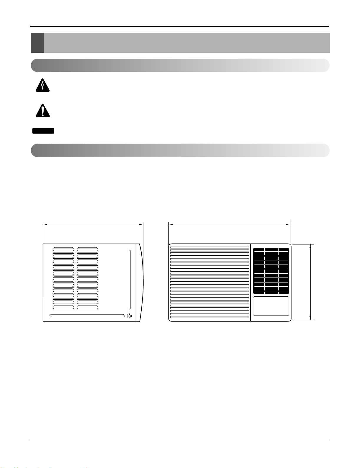
Outside Dimensions
This symbol alerts you to the risk of electric shock.
This symbol alerts you to hazards that could cause harm to the
air conditioner.
This symbol indicates special notes.
NOTICE
Symbols Used in this Manual
470(18 1/2")525(20 11/16")
/8")
7
353(13
Page 7
Product Specifications
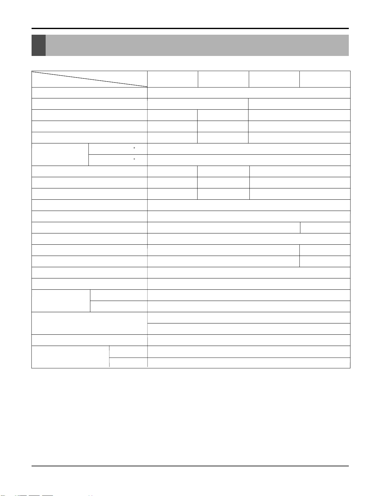
Product Specifications
Product Specifications
Product Specifications
Specfications
MODELS
ITEMS
POWER SUPPLY
COOLING CAPACITY (Btu/h)
INPUT (W)
RUNNING CURRENT (A)
.
.
E.E.R (BTU/W.h)
OPERATING
CONDITION
REFRIGERANT (R-22) CHARGE
EVAPORATOR
CONDENSER
FAN, INDOOR
FAN, OUTDOOR
FAN SPEEDS, FAN/COOLING
FAN MOTOR
OPERATION CONTROL
INDOOR ( C)
OUTDOOR ( C)
.
C)
BG8000ER WG8005R WG1005R WG1205R
1Ø, 115, 60Hz
8,000 10,000 12,000
740 1020 1220
6.8 9.2 11.0
7.6
10.8 9.8
9.8
385g(13.6oz) 260g(9.2oz) 440g(15.5oz) 380g(13.4oz)
Ø9.52, 2ROW 12STACKS
Ø7.0, 2ROW 16STACKS
.0
.0
.0
PROPELLER TYPE FAN WITH SLINGER RING
820
26.7(DB)* 19.4(WB)**
35(DB)* 23.9(WB)**
Ø7.0, 2ROW 14STACKS
Ø5.0, 2ROW 16STACKS
Ø
TURBO FAN
REMOTE CONTROLLER
Ø
7, 3R 14STACKS .7, 2R 14STACKS
Ø7, 2R 16STACKS 5, 2R 18STACKS
3/3
6 POLES
Ø
Ø
ROOM TEMP. CONTROL
AIR DIRECTION CONTROL
CONSTRUCTION
PROTECTOR
POWER CORD
DRAIN SYSTEM
OUTSIDE DIMENSION
(W x H x D)
H x
* DB:Dry Bulb
**
WB:Wet Bulb
COMPRESSOR
FAN MOTOR
(inch)
(mm)
THERMISTOR
HORIZONTAL LOUVER (UP & DOWN), VERTICAL LOUVER (RIGHT&LEFT)
SLIDE IN-OUT CHASSIS
OVERLOAD PROTECTOR
INTERNAL THERMAL PROTECTOR
3 WIRE WITH GROUNDING
ATTACHMENT PLUG (CORD-CONNECTED TYPE)
DRAIN PIPE OR SPLASHED BY FAN SLINGER
18 1/2 x 13 7/8 x 20 11/16 235/8x1431/32x225/16
469 x 353 x 526 380 x 600 x 555
Service Manual 7
Ser 7
Ser 7
7
Page 8
8 Room Air Conditioner
Installation
Installation
Select the Best Location
Installation Check
How to Secure the Drain Pipe
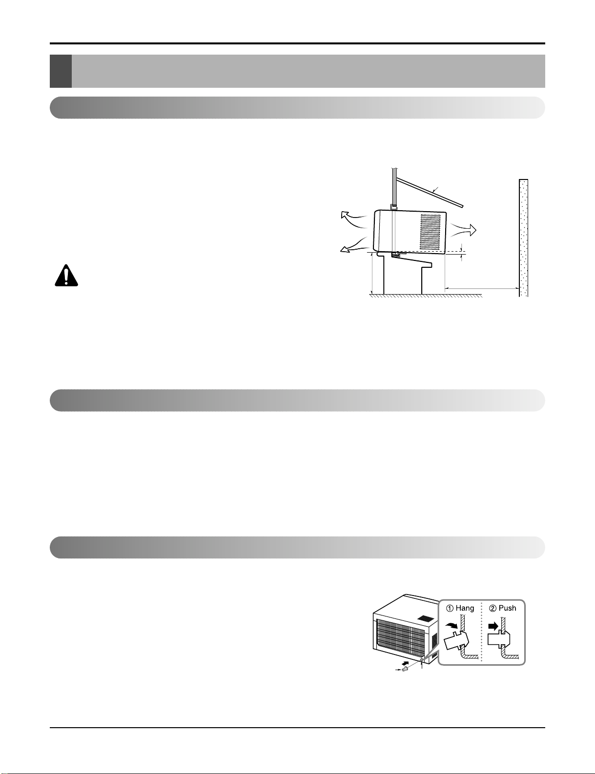
1. To prevent vibration and noise, make sure the unit is installed
securely and firmly.
2. Install the unit where the sun does not shine directly on the
unit.
3. The outside of the cabinet must extend outward for at least
11" and there should be no obstacles, such as a fence or
wall, within 20" from the back of the cabinet because it will
prevent heat radiation of the condenser.
Restriction of outside air will greatly reduce the cooling efficiency of the air conditioner.
CAUTION: All side louvers of the cabinet must
remain exposed on the outdside of the structure.
4. Install the unit slanted slightly so the back is slightly lower
than the front (about 1/
4"). This will force condensed water
to the outside.
5. Install the unit with the bottom about 30"~60" above the
floor level.
The setting conditions must be checked prior to initial starting.
The following items are especially important checking points when the installation is finished.
1. Grounding wire (Green or Green and Yellow) is provided in the power cord. The green wire must be grounded.
2. Connect to a single-outlet 15A circuit.
(or 20A circuit for Electric Heater Model)
3. To avoid vibration or noise, make sure the air conditioner is installed securely.
4 Avoid placing furniture or draperies in front of the air inlet and outlet.
In humid weather, excess water may cause the Base Pan to
overflow. To drain the water, remove the Drain Cap and secure
the Drain Pipe to the rear hole of the Base Pan. (Figure. 2)
ABOUT / "
Over 20"
HEAT
RADIATION
FENCE
AWNING
OUTSIDE
INSIDE
COOLED AIR
30"-60"
1
4
Drain Pipe
Drain Cap
Figure 1
Figure 2
Page 9
Service Manual 9
Installation
How to Install
Window Requirements
All supporting parts should be secured to
firm wood, masonry, or metal.
1. This unit is designed for installation in standard double
hung windows with actual opening widths of 22" to 36".
The upper and lower sash must open sufficiently to allow
a clear vertical opening of 15" from the bottom of the
sash to the window stool.
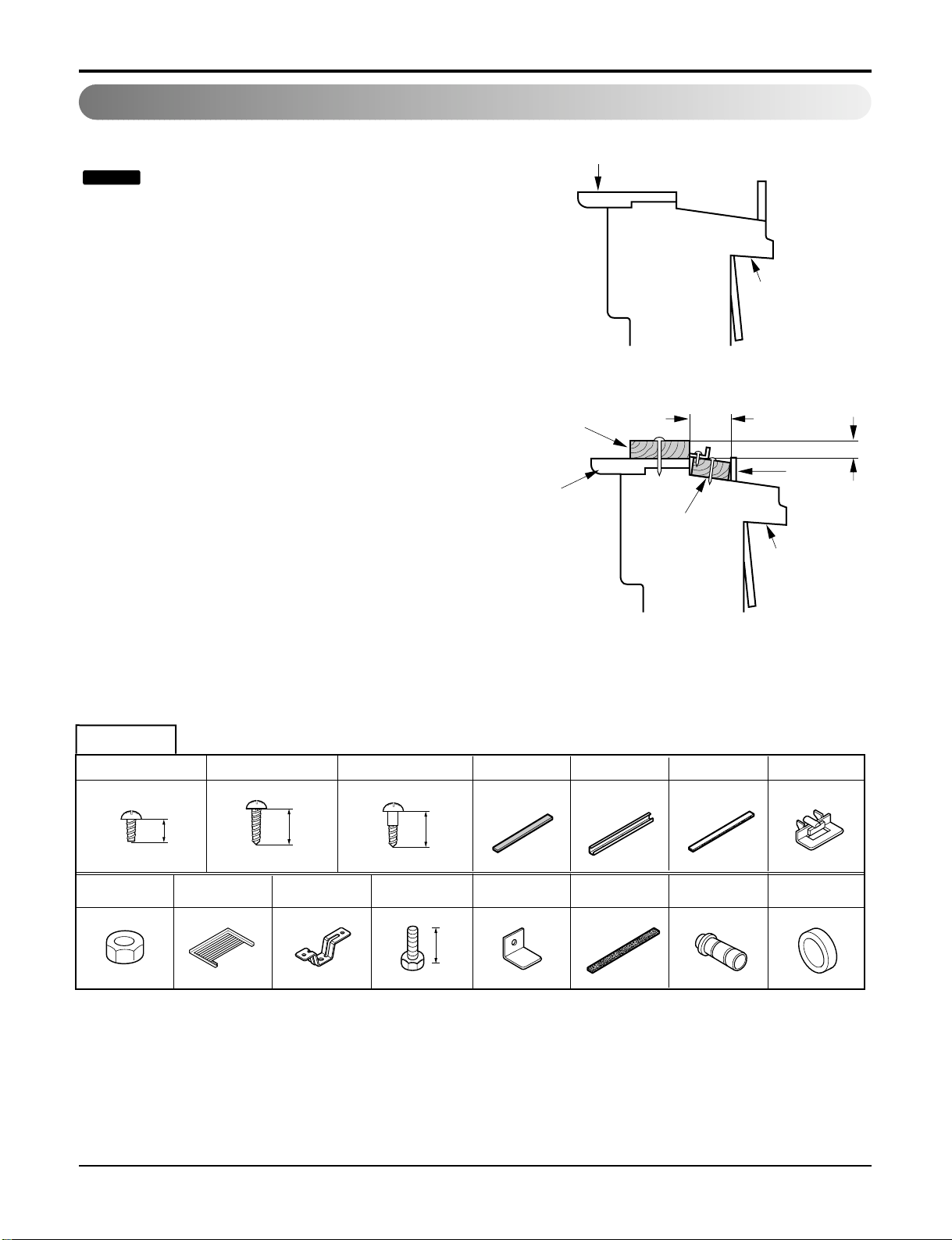
2. If storm window presents interference, fasten a 2" wide
wood strip to the inner window sill across the full width of
the sill. The wood strip should be thick enough to raise
the height of the window sill so that the unit can be
installed without interference by the storm window
frame. See Figure. 4. Top of wood strip should be
approximately 3/4" higher than the storm window frame
(STORM WINDOW FRAME) or wood strip (OUTDOORS) to help condensation to drain properly to the
outside.
3.
Install a second wood strip (approximately 6" long by 11/2"
wide and same thickness as first strip) in the center of the
outer sill flush against the back off the inner sill. This will
raise the L bracket as shown Figure. 4.
4. If the distance between STORM WINDOW FRAME and
WOOD STRIP MOUNTED ON TOP OF INNER SILL is
more than 1", two of wood strip are not necessary.
Installation
NOTICE
OUTDOORSINDOORS
INNER
SILL
OUTER
SILL
INNER
SILL
WOOD STRIP MOUNTED
ON TOP OF INNER SILL
WOOD STRIP
FOR
L
BRACKET
3/4"
CLEARANCE
1" MAX.
STORM
WINDOW
FRAME
OUTDOORSINDOORS
OUTER
SILL
Figure 3
Figure 4
HARDWARE
Type A:16EA
(SCREW)
10mm
Type D:2EA
(NUT)
Type E:2EA
(FRAME CURTAIN)
Type B:3EA
(SCREW)
16mm
Type F:2EA
(SILL SUPPORT)
Type C:5EA
(SCREW)
Type G:2EA
(BOLT)
16mm
10
Type H:1EA
(FOAM-STRIP)
Type L:1EA
(WINDOW LOCKING BRACKET)
Type I:1EA
(UPPER GUIDE)
Type M:1EA
(FOAM-PE)
Type J:1EA
(FOAM-PE)
Type N:1EA
(DRAIN JOINT PIPE)
Type K:2EA
(FRAME-GUIDE)
(DRAIN WASHER)
Type O:1EA
Page 10
10 Room Air Conditioner
Installation
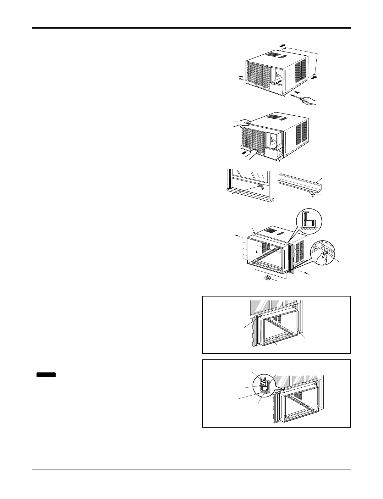
PREPARATION OF CHASSIS
1. Remove the screws which fasten the cabinet at both
sides and at the back.
2. Slide the unit from the cabinet by gripping the base
pan handle and pulling forward while bracing the
cabinet.
3. Cut the window sash seal to the proper length.
Peel off the backing and attach the Foam-Pe
to the
underside of the window sash.
4. Remove the backing from the top Upper Guide FoamPe and attach it to the bottom of the Upper Guide.
5. Attach the Upper Guide onto the top of the cabinet with
3 type A screws.
6. Insert the Frame Guides into the bottom of the cabinet.
7. Insert the Frame Curtain
into the Upper Guide
and Frame Guides .
8. Fasten the curtains to the unit with 4 Type A screws.
CABINET INSTALLATION
1.Open the window. Mark a line on center of the
window stool(or desired air conditioner location).
Carefully place the cabinet on the window stool and
align the center mark on the bottom front with the
center line marked in the window stool.
2. Pull the bottom window sash down behind the Upper
Guide until it meets.
Upper Guide
Upper Guide
Screw
Frame-Guide
(Type A)
Upper Guide
Window Sash
Window stool
Front Angle
Upper guide
Frame Curtain
Foam-pe
Foam-pe
Cabinet
Foam-Pe
Shipping
Screws
Figure 5
Figure 6
Foam-Pe
Frame-Guide
Screw
Screw
(Type A)
(Type A)
NOTICE
Do not pull the window sash down so tightly
that the movement of Frame Curtain is restricted.
Page 11
Service Manual 11
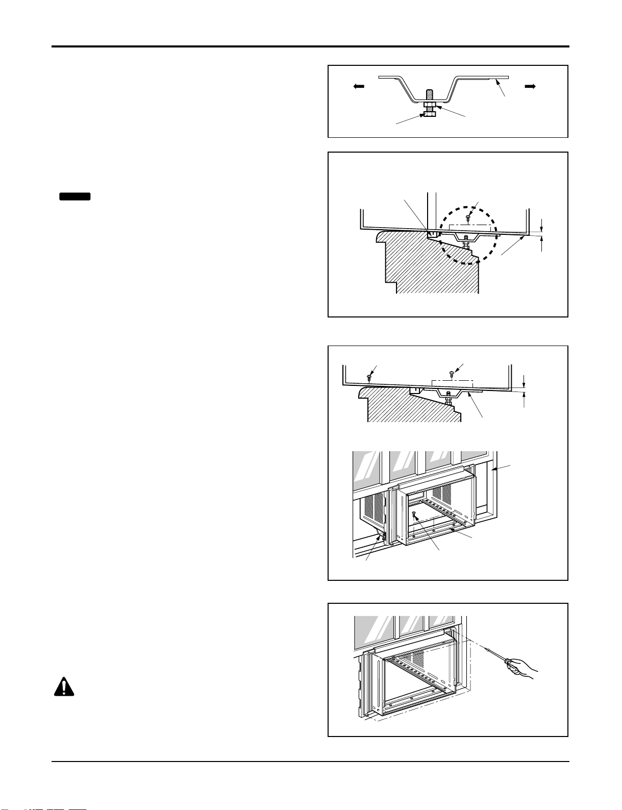
Installation
INDOOR OUTDOOR
Sill Support
Nut
Bolt
INDOOR OUTDOOR
Frame Guide
About 1/2"
Screw(Type A)
Cabinet
About 1/2"
Screw(Type B) Screw(Type A)
Sill support
Sash track
Front Angle
Type C
Screw(Type B)
Sill support
3. Loosely assemble the Sill Support using the parts in
Figure 7.
4. Select the position that will place the Sill Support
near the outer most point on sill (See Figure 8)
5. Attach the Sill Support to the cabinet track hole in
relation to the selected position using 2 Type A
screws in each support(See Figure 8).
6. The cabinet should be installed with a very slight
tilt(about1/2") downward toward the outside (See
Figure 9).
Adjust the bolt and the nut of Sill Support for
balancing the cabinet.
7. Attach the cabinet to the window stool by driving the
screws (Type B: Length sixteen millimeters and
below.) through the front angle into window stool.
8. Pull each Frame Curtain fully to each window sash
track, and repeat step 2.
9. Attach each Frame Curtain the window sash using
screws (Type C).(See Figure 10)
Figure 7
Figure 8
Figure 9
Figure 10
NOTICE
Be careful when you install the cabinet (Frame
Guides are broken so easily).
CAUTION: DO NOT DRILL A HOLE IN THE
BOTTOM PAN.
The unit is designed to operate with approximately
1/2" of water in bottom pan.
Page 12
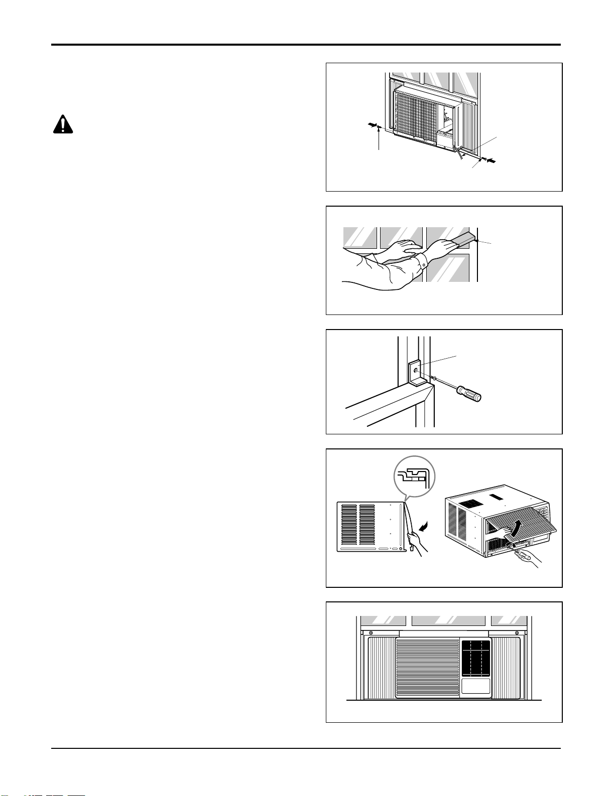
Screw(Type A)
Screw(Type A)
Power cord
Foam-Strip
Window Locking Bracket
10. Slide the unit into the cabinet.(See Figure 11)
11. Cut the Foam-Strip to the proper length and insert
between the upper window sash and the lower
window sash.
(See Figure 12)
12. Attach the Window Locking Bracket with a Type C
screw. (See Figure 13)
13. Attach the front grille to the cabinet by inserting the
tabs on the grille into the tabs on the front of the
cabinet. Push the grille in until it snaps into place.
(See Figure 14)
14. Lift the inlet grille and secure it with a Type A screw
through the front grille.
(See Figure 15)
15. Window installation of room air conditioner is now
completed. See ELECTRICAL DATA for attaching
power cord to electrical outlet.
Figure 11
Figure 12
Figure 13
Figure 16
Figure 15
Figure 14
12 Room Air Conditioner
Installation
CAUTION: For security purpose, reinstall screws
(Type A) at cabinet's sides.
Page 13

Operation
Location and Function of Controls
CAUTION: If you turn off the air conditioner or switch from cooling to the fan, wait
at least 3 minutes before setting to cooling again.
FOR NORMAL COOLING
1. Turn the operation switch to the High Cool or the Low Cool setting.
2. Set the thermostat control to the desired temperature mark (the mid-point is a good starting
position). If the room temperature is not satisfactory after a reasonable time, adjust the control to a cooler or warmer setting, as appropriate.
FOR MAXIMUM COOLING
1. Turn the operation switch to the High Cool setting.
2. Set the thermostat control to the largest temperature mark.
FOR QUIETER OPERATION
1. Turn the operation switch to the Low Cool setting.
2. Set the thermostat control as needed.
• DESIGNED FOR COOLING ONLY
• POWERFUL AND INCREDIBLE COOLING
• TOP-DOWN CHASSIS FOR THE SIMPLE INSTALLATION AND SERVICE
• BUILT-IN ADJUSTABLE THERMOSTAT
• WASHABLE ONE-TOUCH FILTER
• COMPACT SIZE
Service Manual 13
Operation
Operation
O ff - Turns air conditioner off.
Me d Fa n - Med speed fan operation without cooling.
Low Fa n - Low speed fan operation without cooling.
Hig h C oo l - Cooling with high speed fan operation.
Me d C oo l - Cooling with med speed fan operation.
Low C ool - Cooling with low speed fan operation.
Thermostat
5
4
3
6
7
This automatically controls the temperature of the indoor air.
Turn the knob so that arrow points to the larger marks for greater cooling.
Point the arrow to the smaller marks for more moderate cooling.
2
1
8
9
(i.e. the higher the number, the greater the cooling)
Page 14

The controls look like this:
Controls
Auto
Swing
Power
Temp
Fan Speed
Timer Mode
Energy
Saver
1
2
5
4
3
6
Remote Control Operations
1. Power
• To turn the Set ON, push the button. To turn the
Set OFF, push the button again.
• This button takes priority over any other buttons.
• When you first turn it on, the Set is on the High cool
mode and the temp. at 72°F
2. Temperature Setting
• This button controls the room temperature setting
in a range between 60°F and 86°F in 1° increments.
3. Fan Speed
• Pressing the Fan Speed button toggles between
Low and High speeds.
4. On/Off Timer
- Stopping Operation
Each press of the button cycles through the options
in this order:
1 Hour → 2 Hours → 3 Hours → 4 Hours → 5 Hours
→ 6 Hours → 7 Hours → 8 Hours → 9 Hours →
10 Hours → 11 Hours → 12 Hours → CANCLE.
The set temperature will be raised by 2°F after 30
minutes and again after another 30 minutes.
- Starting Operation
Each press of the button cycles through the options
in this order:
1 Hour → 2 Hours → 3 Hours → 4 Hours → 5 Hours
→ 6 Hours → 7 Hours → 8 Hours → 9 Hours →
10 Hours → 11 Hours → 12 Hours → CANCLE.
5. Energy Saver
The fan stops when the compressor stops cooling.
• Approximately every 3 minutes the fan will turn on
and check the room air to determine if cooling is
needed.
6. Cool/Fan/Dry
• Everytime you push this button, it will toggle
between COOL, FAN, and DRY.
How to Insert Batteries
1. Remove the cover from the back of the remote controller
2. Insert two batteries.
• Be sure of the polarity when installing the batteries.
• Be sure that both batteries are new.
3. Re-attach the cover.
• Do not use rechargeable batteries.
Such batteries
differ from standard dry cells in
shape, dimensions, and performance.
• Remove the batteries from the
remote controller if the air conditioner is not going to be used for
an extended length of time.
CAUTION: The Remote Controller will not function properly if strong light strikes
the sensor window of the air conditioner or if there are obstacles between the
Remote Controller and the air conditioner.
14 Room Air Conditioner
Operation
3
4 5
6 2 1
7
Page 15

Disassembly
Disassembly
Mechanical Parts
— Before the following disassembly, POWER SWITCH set to OFF and disconnect the power cord.
1. FRONT GRILLE
1. Open the lnlet grille upward or downward.
2. Remove the screw which fastens the front grille.
3. Pull the front grille from the right side.
4. Remove the front grille.
5. Re-install the component by referring to the
removal procedure, above.(See Figure 17)
2. CABINET
1. After disassembling the FRONT GRILLE, remove
the 2 screws which fasten the cabinet at both
sides.
2. Remove the 2 screws which fasten the cabinet at
back.
3. Pull the base pan forward. (See Figure 18)
4. Remove the cabinet.
5. Re-install the component by referring to the
removal procedure, above.
3. CONTROL BOX
1. Disconnect the unit from the power source.
2. Remove the front grille.
3. Remove the cabinet.
4. Remove the screw which fastens the control box
cover.
5. Remove the housing which connects motor wire
in the control box.
6. Remove the 3 leads from the compressor.
7.Discharge the capacitor by placing a 20,000
ohmresistor across the capacitor terminals.
8. Remove the 2 screws which fasten the control
box.(See Figure 19)
9. Pull the control box forward completely.
10. Re-install the components by referring to the
removal procedure, above. (See Figure 19)
Figure 17
Figure 19
Figure 18
Service Manual 15
Page 16

16 Room Air Conditioner
Disassembly
Air Handling Parts
—7—
1. AIR GUIDE AND BLOWER
1. Remove the front grille.
2. Remove the cabinet.
3. Remove the control box.
4. Remove the 3 screws which fasten the brace.
5. Remove the brace.
6. Remove the 2 screws which fasten the evaporator.
7. Move the evaporator forward and pulling it upward
slightly. (See Figure 20)
8. Move the evaporator to the left carefully.
9. Pull out the hook of orifice by pushing the tabs and
remove it. (See Figure 21)
10. Remove the clamp with a hand plier which
secures the blower.
11. Remove the blower.
12. Remove the 4 screws which fasten the air guide
from the barrier.
13. Move the air guide backward, pulling out from the
base pan.
14. Re-install the components by referring to the
removal procedure, above.
2. FAN AND SHROUD
1. Remove the cabinet.
2. Remove the brace.
3. Remove the 3 screws which fasten the condenser.
4. Move the condenser to the left carefully.
5. Remove the clamp which secures the fan.
6. Remove the fan and then pull out the shroud.
(See Figure 22)
7. Re-install by referring to the removal procedure.
Figure 20
Figure 21
Figure
22
Page 17

Service Manual 17
Electrical Parts
Disassembly
3. MOTOR
1. Remove the cabinet.
2. Remove the evaporator.
3. Remove the orifice.
4. Remove the blower.
5. Remove the fan.
6. Remove the control box cover and housing of the
motor in the control box.
7. Remove the 2 screws which fasten the motor from
the mount motor. (See Figure 23)
8. Remove the motor.
9. Re-install the components by referring to the
removal procedure, above.(See Figure 23)
1. OVERLOAD PROTECTOR
Figure 23
1. Remove the cabinet.
2. Remove the nut which fastens the terminal cover.
3. Remove the terminal cover. (See Figure 24)
4. Remove all the leads from the overload protector.
5. Remove the overload protector.
6. Re-install the component by referring to the
removal procedure, above.
2. COMPRESSOR
1. Remove the cabinet.
2. Discharge the refrigerant system using a Freon
Recovery System.
If there is no valve to attach the recovery system,
install one (such as a WATCO A-1) before venting
the FreonTM. Leave the valve in place after
servicing the system.
3. Remove the overload protector.
4. After purging the unit completely, unbraze the
suction and discharge tubes at the compressor
connections.
5. Remove the 3 nuts and the 3 washers which
fasten the compressor.
6. Remove the compressor. (See Figure 25)
7. Re-install the components by referring to the
removal procedure, above.
Figure 24
TM
Figure 25
Page 18

Disassembly
3. CAPACITOR
MODEL : ROTARY SWITCH TYPE MODEL
1. Remove the control box.
2. Remove the knobs and the screw which fasten
control panel from control box.
3. Remove the screw which is located in the front.
4. Open the bottom side of control box.
5. Remove the screw and the clamp which fasten the
capacitor.
6. Disconnect all the leads of capacitor terminals.
7. Re-install the components by referring to the
removal procedure, above. (See Figure 26)
Figure 26
MODEL : TOUCH & REMOTE CONTROL TYPE MODEL
1. Remove the control box.
2. Remove the screw which fasten control panel from
control box.
3. Remove the screw which located in the front.
4. Open the bottom side of control box.
5. Remove the screw and the clamp which fastens
the capacitor.
6. Disconnect all the leads of capacitor terminals.
7. Re-install the components by referring to the
removal procedure, above. (See Figure 27)
Figure 27
4. THERMOSTAT
MODEL : ROTARY SWITCH TYPE MODEL
1. Remove the control box.
2. Open the control box.
3. Remove the 2 screws which fasten the thermostat.
4. Disconnect 2 leads of thermostat terminals.
5. Remove the thermostat.
6. Re-install the components by refereing to the above
removal procedure. (See Figure 28)
Figure 28
18 Room Air Conditioner
Page 19

6. ROTARY SWITCH
MODEL : ROTARY SWITCH TYPE MODEL
1. Remove the control box.
2. Open the control box.
3. Remove the 2 screws which fasten the rotary switch.
4. Disconnect all the leads of the rotary switch terminals.
5. Remove the rotary switch.
6. Re-install the components by referring to the above
removal procedure. (See Figure 29)
Disassembly
7. POWER CORD
1. Remove the control box.
2. Open the control box.
3. Disconnect the grounding screw from the control
box.
4. Disconnect the 2 receptacles.
5. Remove a screw which fastens the clip cord.
(See Figure 30)
6. Remove the power cord.
7. Re-install the component by referring to the above
removal procedure, above.
(Use only one ground-marked hole for ground
connection.)
8. If the supply cord of this appliance is damaged, it
must be replaced by the special cord. (The
special cord means the cord which has the same
specification marked on the supply cord attached at
the unit.)
Refrigerating Cycle
Figure 29
Figure 30
CAUTION: Discharge the refrigerant system using a Freon
to attach the recovery system, install one (such as a WATCO A-1) before venting the FreonTM. Leave
the valve in place after servicing the system.
1.
CONDENSER
1. Remove the cabinet.
2. Remove the 3 screws which fasten the
brace.
3. Remove the 3 screws which fasten the condenser
and shroud.
4. After discharging the refrigerant completely,
unbraze the interconnecting tube at the condenser
connections.
5. Remove the condenser carefully.
6. Re-install the component by referring to notes.
(See Figure 31)
TM
Figure 31
Recovery System. If there is no valve
Service Manual 19
Page 20

20 Room Air Conditioner
Disassembly
— Replacement of the refrigeration cycle.
1. When replacing the refrigeration cycle, be sure to
Discharge the refrigerant system using a Freon
TM
recovery System.
If there is no valve to attach the recovery system,
install one (such as a WATCO A-1) before venting
the FreonTM. Leave the valve in place after
servicing the system.
2. After discharging the unit completely, remove the
desired component, and unbraze the pinch-off
tubes.
3. Solder service valves into the pinch-off tube ports,
leaving the valves open.
4. Solder the pinch-off tubes with Service valves.
5. Evacuate as follows.
1) Connect the vacuum pump, as illustrated figure
33A.
2) Start the vacuum pump, slowly open manifold
valves A and B with two full turns counterclockwise and leave the valves open.
The vacuum pump is now pulling through valves
A and B up to valve C by means of the manifold
and entire system.
CAUTION: If high vacuum equipment is used, just crack valves A
and B for a few minutes, then open
slowly with the two full turns counterclockwise. This will keep oil from foaming
and being drawn into the vacuum pump.
3) Operate the vacuum pump vaccum for 20 to 30
minutes, until 600 microns of vaccum is
obtained. Close valves A and B, and observe
vacuum gauge for a few minutes. A rise in pressure would indicate a possible leak or moisture
remaining in the system. With valves A and B
closed, stop the vacuum pump.
4) Remove the hose from the vacuum pump and
place it on the charging cylinder. See figure
37B. Open valve C.
Discharge the line at the manifold connection.
5) The system is now ready for final charging.
6. Recharge as follows :
1) Refrigeration cycle systems are charged from
the High-side. If the total charge cannot be put
in the High-side, the balance will be put in the
suction line through the access valve which you
installed as the system was opened.
2) Connect the charging cylinder as shown in figure
33B.
With valve C open, discharge the hose at the
manifold connection.
3) Open valve A and allow the proper charge to
enter the system. Valve B is still closed.
4) If more charge is required, the high-side will not
take it. Close valve A.
5) With the unit running, open valve B and add the
balance of the charge.
a.
Do not add the liquid refrigerant to the Low-side.
b. Watch the Low-side gauge; allow pressure to
rise to 30 lbs.
c. Turn off valve B and allow pressure to drop.
d. Repeat steps b. and c. until the balance of the
charge is in the system.
6) When satisfied the unit is operating correctly,
use the pinch-off tool with the unit still running
and clamp on to the pinch-off tube. Using a tube
cutter, cut the pinch-off tube about 2 inches from
the pinch-off tool. Use sil-fos braze and braze
pinch-off tube closed. Turn off the unit, allow it to
set for a while, and then test the leakage of the
pinch-off connection.
NOTICE
2. EVAPORATOR
1. Remove the cabinet.
2. Remove the 2 screws which fasten the evaporator.
3. Move the evaporator sideways carefully.
4. After discharging the refrigerant completely,
unbraze the interconnecting tube at the evaporator
connections.
5. Remove the evaporator carefully.
6. Re-install the component by referring to notes.
(See Figure 32)
3. CAPILLARY TUBE
1. Remove the cabinet.
2. After discharging the refrigerant completely,
unbraze the interconnecting tube at the capillary
tube.
3. Remove the capillary tube.
4. Re-install the component by referring to notes.
Figure 32
Page 21

Service Manual 21
Disassembly
Equipment needed: Vacuum pump, Charging cylinder, Manifold gauge, Brazing equipment. Pin-off tool capable
of making a vapor-proof seal, Leak detector, Tubing cutter, Hand Tools to remove components, Service valve.
A
COMPOUND GAUGE
EVAPORATOR
(LOW PRESSURE SIDE)
COMPRESSOR
CAPILLARY TUBE
CONDENSER
(HIGH PRESSURE SIDE)
SEE INSETS
BELOW
MANIFOLD
GAUGE
B
Figure 33A-Pulling Vacuum
Figure 33B-Charging
A
B
EXTERNAL
VACUUM PUMP
A
CHARGING
CYLINDER
LOW
HI
B
C
Page 22

Schematic Diagram
Schematic Diagram
Wiring Diagram
MODEL : ROTARY SWITCH TYPE MODEL
P OW E R IN PU T
B K( BR )
(P lain)
R OT AR Y S WIT C H
R D
R D
L7
8
6
4
3
5
3
1
C OMP .
H
M
4
2
B L
R
S
C
T HE R MOS T AT
B R (YL )
B K
B K
B L
B L
OR ( BR )
Y L
B K
R D
B L
OL P
MO T OR
Y L
OR ( BR )
B K
R D
B L
5
WH (B L)
(R ibbed)
G N(G N/YL )
G N(G N/YL )
C AP ACI TO R
F
C
H
B K
R D
P .T .C
1
2
6
8
WIR ING DIA G R AM 3854AR 3563A
7
LOCATION
NO.
POWER CORD ASSY
1
FAN MOTOR
2
COMPRESSOR
3
ROTARY SWITCH
4
THERMOSTAT
5
CAPACITOR
6
OVERLOAD PROTECTOR
7
8
P.T.C
22 Room Air Conditioner
DESCRIPTION
Q'TY
PER SET
1
1
1
1
1
1
1
1
S: Service Parts
N: Non Service Parts
REMARKS
S
S
S
S
S
S
S
S
Page 23

Service Manual 23
Schematic Diagram
Circuit Diagram
MODEL : TOUCH & REMOTE CONTROL TYPE MODEL
LOCATION
NO.
1
2
3
4
5
6
7
8
Q'TY
PER SET
1
1
1
1
1
1
1
1
DESCRIPTION
POWER CORD ASSEMBLY
FAN MOTOR
COMPRESSOR
DISPLAY P.W.B ASSEMBLY
MAIN P.W.B ASSEMBLY
THERMISTOR
CAPACITOR
OWERLOAD PROTECTOR
2
7
1
6
4
3
8
5
Page 24

24 Room Air Conditioner
Electronic Control Device
Schematic Diagram
Page 25

Components Location(For Main P.W.B ASM)
Schematic Diagram
Service Manual 25
Page 26

26 Room Air Conditioner
Troubleshooting Guide
Troubleshooting Guide
Piping System
Figure 38 is a brief description of the important components and their function in what is called the refrigeration
system. This will help you to understand the refrigeration cycle and the flow of the refrigerant in the cooling cycle.
MOTOR
COMPRESSOR
OIL
(LIQUID REFRIGERANT)
CAPILLARY TUBE
OUTSIDE COOLING
AIR FOR REFRIGERANT
PASS THROUGH
SUCTION LINE
COOL LOW PRESSURE VAPOR
COOLED
AIR
COMPLETE LIQUID
BOIL OFF POINT
LIQUID
PRESSURE
DROP
ROOM AIR HEAT LOAD
VAPOR INLET
HOT
DISCHARGED
AIR
LIQUID OUTLET
HIGH PRESSURE VAPOR
LIQUID REFRIGERANT
LOW PRESSURE VAPOR
ROOM AIR CONITIONER
EVAPORATOR COILS CONDENSER COILS
CYCLE OF REFRIGERATION
Figure 34
CONDENSER COIL
FAN
CAPILLARY TUBE
MOTOR
COMPRESSOR
BLOWER
EVAPORATOR COIL
Page 27

Service Manual 27
Troubleshooting Guide
Troubleshooting Guide
In general, possible trouble is classified in two kinds.
The one is called Starting Failure which is caused from an electrical defect, and the other is ineffective Air
Conditioning caused by a defect in the refrigeration circuit and improper application.
Unit runs but poor cooling.
Ineffective Cooling
Satisfactory operation
with temperature
difference of inlet & outlet
air; 44~50°F (7~10°C)
Replacement of unit if
the unit is beyond repair.
Check outdoor coil
(heat exchanger) and
fan operation.
Check heat load
increase.
Check cold air
circulation for smooth
flow.
Check gas leakage.
Clean condenser.
Not on separate circuit
Check inside gas
pressure.
Adjust refrigerant
charge.
Malfunction of
compressor.
Replacement of
compressor.
Check clogging in refrigeration circuit.
Repair clogging in
refrigeration circuit.
Dirty indoor coil
(heat exchanger)
Repair gas leak.
Malfunction of fan.
Clogging of air filter.
Obstruction at air outlet.
Remove obstruction.
Page 28

28 Room Air Conditioner
Troubleshooting Guide
Fails to Start
Improper thermistor
setting
Loose terminal
connection
Improper wiring
Check of power source.
Drop of power voltage.
Capacitor check.
Replacement.
Check of control panel
setting.
Compressor fails only to
start.
Defect of compressor
capacitor.
Replacement of compressor
(Motor damaged).
Irregular motor insulation (Ω)
Irregular motor resistance (Ω)
Check of circuit breaker
and fuse.
Check control panel.
Fan only fails to start.
Improper wiring.
Defect of fan motor
capacitor.
Replacement of fan motor.
Regular but fails to start.
Replacement of compressor.
(Locking of piston, metal.)
Irregular motor
resistance (Ω)
Irregular motor
insulation (Ω)
Page 29

Service Manual 29
Troubleshooting Guide
■ MODEL : BG8000ER, WG8000RY4, WG1000RY4
ELECTRIC PARTS TROUBLESHOOTING GUIDE:
Possible Trouble 1
• The unit does not operate.
Is the Trans input power
AC 115V?
Is the Trans output power
about AC 14V?
Is shorted the Trans. output?
Is output Voltage of IC01D
DC 12V?
Is output Voltage of IC02D
DC 5V?
Is the voltage No.18 of Micom
DC 5V?
Exchange Main P.W.B Ass'y.
Is the
connection between
Main and Display
all right?
Is the reset circuit all right?
(The No.14 of Micom
is 5V.)
•
Check the Fuse.
•
Check the wiring diagram.
•
Check the Main
P.W.B pattern.
• Exchange the Trans.
•
Exchange D02D~D05D.
• Exchange IC01D.
• Exchange IC02D.
• Exchange IC01A.
• Connect connector
exactly.
• Check the
P.W.B
pattern.
NO
NO
NO
NO
NO
NO
NO
YES
YES
YES
YES
YES
YES
YES
NO
YES
Page 30

30 Room Air Conditioner
Troubleshooting Guide
Is Temp.
setting set lower than Room
Temp.-0.5°C?
Is the voltage No.10
of IC01M 0V?
• Exchange IC01M.
• Set the Temp. setting to lower Temp.
• Wait 3 Minutes
Is the Unit for 3 minutes
delay?
• Exchange MAIN
P.W.B Ass'y.
Is the voltage N0.7 of
IC01M DC 5V?
• Check the RY-COMP.
• Check the wiring
Diagram.
NO
NO
NO NO
YES
YES
YES
YES
Possible Trouble 2
• The compressor does not operate.
Is the wire connection of
RY-COMP all right?
• Check the RY-COMP.
• Connect LEAD Wire to
RY-COMP again.
NO
YES
Possible Trouble 3
• The compressor always operate.
• Exchange IC01M.
• Exchange IC01M.
Is the voltage NO.1 or 4
of IC01M DC 5V?
Is the voltage NO.13 or 16
of IC01M 0V?
• Check the RY-Hi or
RY-Lo.
•
Check the wiring diagram.
NO
NO
YES
YES
Possible Trouble 4
• Fan does not operate.
Page 31

Service Manual 31
Troubleshooting Guide
Is the voltage of Battery
about over 2.3V?
•
Exchange Receiver Ass'y.
Is the connection of
CN-DISP1 all right?
Is the voltage No.16
of CN-DISP1 on Main P.W.B
Ass'y DC 5V?
• Exchange the battery.
•
Check the P.W.B pattern.
• Connect connector to
CN-DISP1 exactly.
NO
NO
NO
YES
YES
YES
Possible Trouble 5
• Romote controller does not operate.
NO
NO
NO
NO
YES
YES
YES
Is the IC01G all right?
Is the connection of
CN-DISP1 all right?
• Exchange the display
P.W.B Ass'y.
• Exchange IC01G.
• Exchange Q01G,
Q02G, Q03G, Q04G
• Connect connector
to CN-DISP1 exactly.
Does the Q01G,
Q02G, Q03G Q04G operate normally
on main P.W.B Ass'y?
Possible Trouble 6
• It displays abnormally on Display P.W.B Ass'y.
Page 32

32 Room Air Conditioner
Troubleshooting Guide
ROOM AIR CONDITIONER VOLTAGE LIMITS
NAME PLATE RATING MINIMUM MAXIMUM
115V ± 10% 103.5V 126.5V
COMPLAINT CAUSE REMEDY
Fan motor will not run. No power Check voltage at outlet. Correct if none.
Power supply cord Check voltage to rotary switch. If none, check
power supply cord. Replace cord if circuit is
open.
Rotary switch Check switch continuity. Refer to wiring diagram
for terminal identification. Replace switch if
defective.
Wire disconnected or Connect wire. Refer to wiring diagram for
connection loose terminal identification. Repair or replace loose
terminal.
Capacitor (Discharge Test capacitor.
capacitor before testing.) Replace if not within ±10% of manufacturer's
rating. Replace if shorted, open, or damaged.
Will not rotate Fan blade hitting shroud or blower wheel hitting
scroll. Re-align assembly.
Units using slinger ring condenser fans must
have 0.22~0.25 inch clearance to the base.
If necessary, shim up the bottom of the fan motor
with mounting screw(s).
Check fan motor bearings; if motor shaft will not
rotate, replace the motor.
Fan motor runs. Revolves on overload Check voltage. See limits on this page.
If not within limits, call an electrician.
Test capacitor.
Check bearings. Does the fan blade rotate
freely?
If not, replace fan motor.
Pay attention to any change from high speed to
low speed. If the speed does not change,
replace the motor.
Page 33

Service Manual 33
Troubleshooting Guide
COMPLAINT CAUSE REMEDY
Fan motor noise. Fan If cracked, out of balance, or partially missing,
replace it.
Blower If cracked, out of balance, or partially missing,
replace it.
Loose set screw Tighten it.
Worn bearings If knocking sounds continue when running or
loose, replace the motor. If the motor hums or
noise appears to be internal while running,
replace motor.
Compressor will not run, Voltage Check voltage. See the limits on the preceding
fan motor runs. page. If not within limits, call an electrician.
Wiring Check the wire connections; if loose, repair or
replace the terminal. If the wires are discon-
nected, refer to wiring diagram for identification,
and replace the wires. Check the wire connections;
If not according to the wiring diagram, correct
the connections.
Thermistor Check the TEMP control. If not at the lowest
number, set TEMP control to this setting and
restart the unit.
Check the continuity of the thermistor. Replace
the thermistor if the circuit is open.
Rotary Check for continuity, refer to the wiring diagram
for terminal identification. Replace the switch if
the circuit is open.
Thermostat Check the position of knob. If not at the coldest
setting, advance the knob to this setting and
restart the unit.
Check the continuity of the thermostat. Replace
the thermostat if the circuit is open.
Capacitor (discharge Check the capacitor.
capacitor before Replace if not within ±10% of manufacturer’s
servicing.) rating, replace if shorted, open, or damaged.
Compressor Check the compressor for open circuit or
ground. If open or grounded, replace the
compressor.
Overload
Check the compressor overload if externally mounted.
Replace if open. (If the compressor temperature is
high, remove the overload, cool, and retest.)
Page 34

34 Room Air Conditioner
COMPLAINT CAUSE REMEDY
Compressor cycles on Voltage Check the voltage. See the limits on the
overload. preceding page. If voltage is not within these limits,
call an electrician.
Overload Check overload, if externally mounted.
Replace if open. (If the compressor temperature
is high, remove the overload, cool, and retest.)
Compressor cycles on Fan motor If not running, determine the cause. Replace if
overload. required.
Condenser air flow Remove the cabinet, inspect the interior surface
restriction of the condenser. If restricted, clean carefully
with a vacuum cleaner (do not damage fins) or
brush. Clean the interior base before
re-assembling.
Condenser fins If the condenser fins are closed over a large
(damaged) area on the coil surface, head pressures will
increase, causing the compressor to cycle.
Straighten the fins or replace the coil.
Capacitor Test the capacitor.
Wiring Check the terminals. If loose, repair or replace.
Refrigeration system Check the system for a restriction.
Insufficient cooling Air filter If restricted, clean or replace.
Unit undersized Determine if the unit is properly sized for the
area to be cooled.
Excessive noise Blower or fan Check the set screw, or clamp. If loose or miss-
ing, correct. If the blower or fan is hitting scroll
or barrier, rearrange the air handling parts.
Copper tubing Remove the cabinet and carefully rearrange the
tubing not to contact the cabinet,
compressor, shroud, and barrier.
Troubleshooting Guide
Page 35

Exploded Vie w
554030
266003
W0CZZ
135500
249950
149410
359011
552113
552102
35211A
352113
731273
130910
749740
Exploded View
267110
135303
354210
152302
W48602
349480
359012
148000
349600
346811
352380
W48602
149980
349001
567502
269300
237200
147582
147581
264100
130410
135312
554160
550140
W5210E-2
W5210E-1
Service Manual 35
Page 36

Exploded Vie w
554030
359011
552113
552102
35211A
352113
731273
130910
749740
Exploded View
267110
135303
354210 W48602
152302
349480
359012
148000
349600
346811
352380
W48602
149980
349001
567502
147582
147581
130410
135312
249950
567480
W0CZZ
268711-1
238310
264100
237200 135500
268711-2
554160
550140
W5210E-2
W5210E-1
Service Manual 35
Page 37

WG1205R WG1005R BG8000ER WG8005R
130410
BASE ASSY,SINGLE
3041A20012R 3041A30011D R
130910
CABINET ASSY,SINGLE
3091AR2286X R
135312
GRILLE ASSY,FRONT(SINGLE)
3531A21008A R
135303
GRILLE ASSY,INLET
3530A10181A R
135500
COVER,CONTROL(INDOOR)
3550AR7032A R
147581
LOUVER,HORIZONTAL
4758A20051A R
147582
LOUVER,VERTICAL
4758AR7308A R
148000
SUPPORTER
4800A10001A R
149980
SHROUD
4998A10020A 4998A10019A R
152302
FILTER, A/C
5231AR1152A R
237200
PANEL ASSY,CONTROL
3720A10003A R
238310
ESCUTCHEON
MDD36626103 R
249950
CONTROL BOX ASSY(SINGLE)
4995A30014B 4995A20296E 4995A10102Q 4995A20296D R
264100
POWER CORD ASSY
6411A20056K 6411A20048R R
267110
REMOTE CONTROLLER
R
268711-1
PWB(PCB)ASSY,DISPLAY
6871A20611D R
268711-2
PWB(PCB)ASSY,MAIN
R
346811
MOTOR ASSY,SINGLE
4681A20073B 4681A20027J R
349001
DAMPER,VENTILATION
4900AR7024B R
349480
ORIFICE
4948A10005B R
349600
MOUNT,MOTOR
4960A20005A R
352380
AIR GUIDE ASSY
5239A20027B R
359011
FAN,AXIAL
5900A10009B R
359012
FAN,TURBO
5900A20030A R
354210
EVAPORATOR ASSY,FIRST
5421AR2910D 5421A20061H 5421A20132B 5421A20061G R
554030
CONDENSER ASSY,FIRST
5403A20083D 5403A20092D R
352113
TUBE ASSY,DISCHARGE
5211A20644A 5211AR2930Z 5211A21201A 5211A20208D R
35211A
TUBE ASSY,SUCTION
5211A20643A 5211A20130R 5211A20130S 5211A20130M R
552102
TUBE CAPILLARY BEND
5211A30260W 5211A20598B 5211A30260F 5211A30260B R
552113
TUBE ASSY CONDENSER OUT
5211A10067E 5211AR7059A 5211AR3399A 5211A10067G R
W5210E-1
TUBE EVAPORATOR
5210A20351E 5210A21847A R
W5210E-2
TUBE EVAPORATOR
5210A20351F 5210A21847B R
554160
COMPRESSOR
2520UCBK003 2520UCDK004 5416A90007A 2520UCBA002 R
567480
THERMISTOR ASSY
6323A20003D R
567502
O.L.P
6750UL029A 6750UL031A 6750A30001N 6750UL048A R
550140
ISOLATOR,COMP
5040AR4195A R
731373
INSTALL PARTS ASSY,SINGLE
3127A20074J R
749740
GUIDE
4974AR3262K R
W48602
CLAMP,SPRING
R
W0CZZ
CAPACITOR
R
3041A30005P
3091A30005R
3531A20034A
3530A10027A
3550A30036A
4758A20002A
4758A30008A
4800A30001A
4998A10010A
5231A20004A
3720A20053A
3831A20015R
6411A20048T
6711A20066A
6871A20443B
6871A10123F
4681A20073A
4901A30001A
4948A30007B
4960A20014A
5239A30002D
5900A20015A
5900A10008A
4830AR4335A
-
-
-
6323A20003S
3127A20074D
-
3H02932B
0CZZA20001N
0CZZA20005B
LOCATION
NO.
DESCRIPTION
PART NO.
REMARK
Page 38

P/No. : 3828A26005A
December, 2004
Printed in China
 Loading...