

Page 1
THE FOLLOWING PARTS ARE NOT SUPPLIED WITH THE OVEN EXCEPT DUCT CONNECTOR.
NOTE: Depending on your ventilation requirements, you may not use all of these parts.
NOTE: You need to install at least one lag screw into a 2" x 4" stud and four anchor bolts into the wall.
The mounting area must meet the 150 lbs. weight requirement.
- 5 -
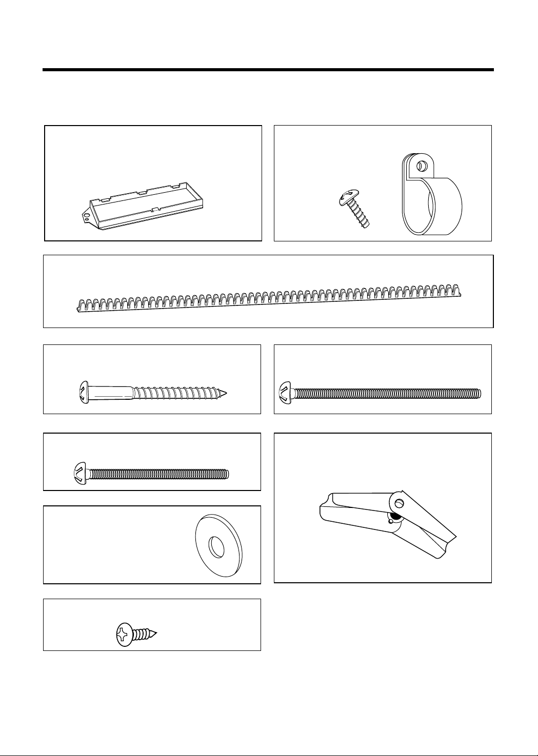
INSTALLATION HARDWARE
Duct connector
(for roof-venting or wall-venting installation)
Not Actual Size
One power cord clamp and
One dark-colored mounting screw
(to hold the power cord)
Actual Size
One power cord clamp bushing - Actual Size
(for the cord hole in a metal upper cabinet)
Four 1/4" x 2" lag screws - Actual Size
(for wall stud holes)
Two 1/4" x 2" bolts - Actual Size
(for securing to the upper cabinet)
Two washers - Actual Size
(for the two upper cabinet bolts)
Two self - tapping screws - Actual Size
(for attaching the damper duct connector)
Four 1/4" x 3" toggle bolts - Actual Size
(for drywall holes)
Four spring toggle heads - Actual Size
(for the toggle bolts)
Page 2
- 6 -
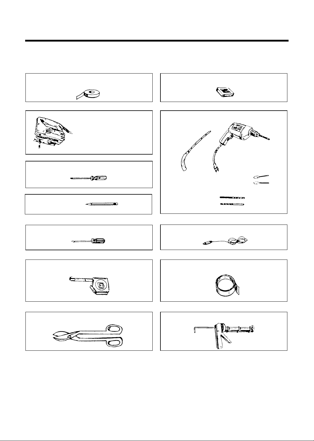
YOU WILL NEED THE FOLLOWING TOOLS AND MATERIALS FOR THE INSTALLATION:
Carton or other heavy material for covering the counter top.
• If you have brick or masonry walls, you will need special hardware and tools.
• The ductwork you need for the installation is not included. All wall and roof caps must have a back-draft
damper.(Shown on page 5.)
Clear tape
(for taping the templates to the wall)
Stud finder or thin nail.
Saber saw (for cutting vent
holes for roof or wall venting)
Keyhole saw (for the power cord hole)
Electric drill
3/8" and 3/4" wood drill bits
1/2" and 3/16"
drill bits
Phillips screwdriver (for the screws)
Pencil
Flat blade screwdriver (for the mounting rod)
Measuring tape (metal preferred)
Small side cutters or tin snips
Caulking gun
Plumb line
Duct Tape
Page 3
- 7 -
AVOID ELECTRICAL SHOCK! THIS APPLIANCE MUST BE GROUNDED!
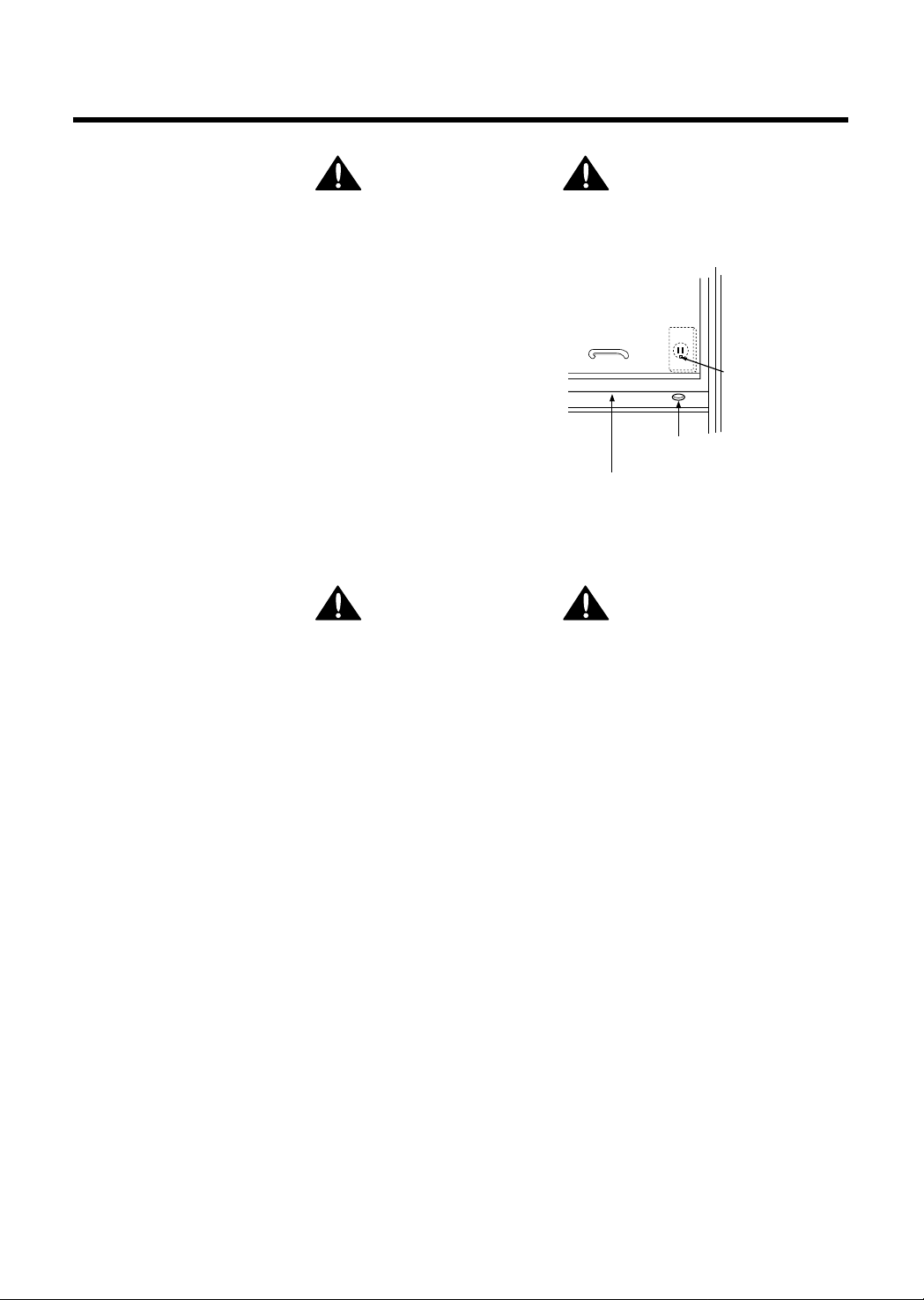
1. Locate the grounded electric outlet for this oven in the cabinet
above the oven, as shown in Figure 5.
NOTE: The outlet should be on a circuit dedicated to the
microwave oven (120V, 60Hz., AC only) with a
15 or 20A fused electrical supply.
IMPORTANT: If you do not have the proper wall outlet, you
MUST have one installed by a qualified
electrician.
2. Attach the upper cabinet template to the upper cabinet wall
with clear type and cut the power-supply-cord hole (shown in
Figure 5) later when you prepare the wall and upper cabinet in
Step 4.
NOTE: Do not use an extension cord.
Keep the power cord dry and do not pinch or crush it.
Improper grounding could result in
electric shock or other personal injury.
• DO NOT, UNDER ANY CIRCUMSTANCES, REMOVE THE POWER SUPPLY
CORD GROUNDING PRONG!
This appliance MUST be grounded!
STEP1: PREPARE THE
ELECTRICAL CONNECTIONS
Grounded Outlet
( Inside Cabinet )
Upper
Cabinet
Upper Cabinet
Template
Power Supply
Cord Hole
Figure 5
W A R N I N G
W A R N I N G
Page 4
- 8 -
NOTE: The ductwork you need for outside ventilation is not included with your oven. The standard
ductwork fittings and length are shown in Figure 10, page 9.
THIS OVEN MUST BE PROPERLY VENTED!
You may vent your oven in one of three ways. However, do NOT vent into a wall cavity, an attic,
or an unused area.
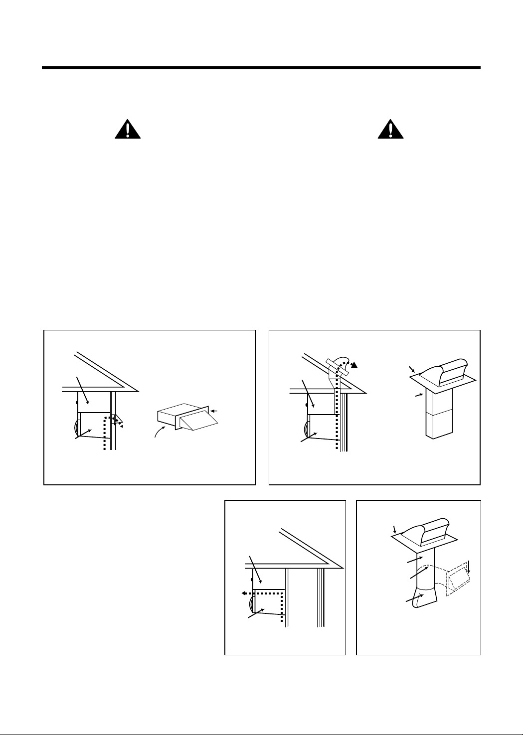
Roof-venting If your oven is located on an outside wall near the roof, as in Figures 7 (31/4" x
10" duct) and 9 (6" round duct.)
Wall-venting If your oven is located on an outside wall of your house, as in Figure 6 (31/4" x 10"
duct) and Figure 9 (6" round duct.)
Room-venting If your oven is located on an inside wall of your house, as in Figure 8.
NOTE: If you choose the rear exhaust method (roof-or wall-venting), be sure there is enough clearance
within the wall for the exhaust duct.
REMEMBER AS YOU INSTALL THE
VENTING:
• Keep the length of the ductwork and the
number of elbows to a minimum to
ventilate your oven efficiently.
See examples on page 9.
• Keep the size of the ductwork the same.
• Do not install two elbows together.
• Use duct tape to seal all joints in the duct
system.
• Use caulking to seal the exterior wall or
roof opening around the cap.
STEP 2:
PREPARE THE VENTING SYSTEM
Wall Venting
Wall venting
through-the-wall
wall cap
3 1/4"x10"
duct
Figure 6
cabinet
oven
W A R N I N G -F I R E H A Z A R D
cabinet
oven
cabinet
oven
Roof venting
Room Venting
Figure 8
Roof Venting
roof cap
3 1/4"x10"
duct
Figure 7
roof cap
6" min.
diameter
round duct
elbow
3 1/4" to round
duct transition
Figure 9
through-the-roof
wall cap
3 1/4" to round
ductwork transition
Page 5

- 9 -
STANDARD FITTINGS
NOTE: If the existing duct is round, you must use a rectangular-to-round adapter, with a rectangular 3"
extension duct installed between the damper assembly and the adapter to prevent the exhaust
damper’s sticking.
DUCT LENGTH
The total length of the duct system, including straight duct, elbows, transitions, and wall or roof caps must
not exceed the equivalent of 140 feet.
For best performance, do not use more than three 90 degree elbows.
Below are the standard fittings and their equivalent length in feet.
To calculate the equivalent length of each ductpiece used, see the examples below.
STEP 2:
PREPARE THE VENTING SYSYTEM
Figure 10
1
4567
23
3 1/4"x10"
to 6"=5ft.
90ß elbow
=10ft.
45ß elbow
=5ft.
3 1/4"x10"
wall cap
=40ft.
3 1/4"x10"
flat elbow
=10ft.
3 1/4"x10" roof
cap=24ft.
3 1/4"x10" 90ß
elbow=25ft.
Examples
For 3 1/4"x10" SYSTEMS
1-3 1/4" x 10" 90ß elbow
1-Wall Cap
8 feet straight duct
TOTAL LENGTH
1-transition
2-90ß elbows
1-Wall Cap
8 feet straight
TOTAL LENGTH
For 6" ROUND SYSTEMS
6ft.
2ft.
2ft.
3 1/4"x10"
90ß elbow
wall cap
6ft.
90ß elbows
transition
wall cap
= 25 ft.
= 40 ft.
= 8 ft.
= 73 ft.
= 5 ft.
= 20 ft.
= 40 ft.
= 8 ft.
= 73 ft.
Page 6

- 10 -
Your microwave oven is shipped with the vent motor assembled for wall venting. If you want roof-venting or
room-vented (recirculating) installation, you must change the fan, as detailed below.
ELECTRICAL SHOCK HAZARD!
UNPLUG UNIT BEFORE WORKING ON IT.
• DO NOT PULL OR STRETCH THE BLOWER WIRING! Pulling and stretching the blower wiring could
result in electrical shock.
WALL-VENTED INSTALLATION:
1. Remove ventgrille by removing two screws on the
ventgrille
2. Turn two mounting rods anti-clockwise with flat
blade screwdriver and take off the mounting plate
from the unit. See figure 11.
3. The vent motor in your microwave oven is installed
for wall vented installation at shipping.
ROOF-VENTED INSTALLATION:
1. Remove ventgrille by removing two screws on the
ventgrille
2. Turn two mounting rods anti-clockwise with flat
blade screwdriver and take off the mounting plate
from the unit. See figure 11.
3. Detach mount-all from out case by removing two
mount-all mounting screws and one motor
mounting screw. See figure 12.
4. Keep the motor wire being connected , lift up,
rotate and reattach the motor so that the exhaust
ports face the upper of the cabinet. See figure 13.
5. Use side cutters or tin snips to cut and remove
knockouts from mount-all. Be careful not to distort
the plate. See figure 14.
6. Reattach the mount-all on the cabinet with three
screws.
STEP 3:
PREPARE THE VENT MOTOR
mount-all
mounting screws
mount-all
motor
mounting screw
Vent motor
Figure 12
Figure 13
back plate
exhaust ports
motor wire
Remove
mounting
plate.
Figure 11
Vent Grille
Controller
Mounting
Plate
Mounting
Rod
Door
Out Case
Mount-all
Flat blade
screw driver
(2-screw positions
are optional.)
W A R N I N G
Page 7

- 11 -
ROOM-VENTED (Recirculating)
INSTALLATION:
1. Remove one motor mounting screw and two
mount-all mounting screws. Take off the mount-all
from the oven. See Figure 15.
2. Carefully lift the vent motor of the microwave oven.
3. Rotate the vent motor 180˚ so the exhaust ports
face the front of the cabinet. See Figure 16.
4. Place the motor back into microwave oven.
5. Reattach mount-all to microwave oven. Attach
motor mounting screw and then two mount-all
mount screws. See Figure 15.
6. Install a charcoal filter to the front of oven.
Figure 14
Figure 15
Figure 16
mount-all
Knockouts
motor
mounting screw
Vent motor
Use side cutters or tin snips.
exhaust
ports
motor wire
Page 8

- 12 -
BEFORE YOU START
1. Remove any shipping materials and parts from inside
the microwave oven.
2. Cover the counter top or cooktop with a thick, protective
covering to protect it from damage and dirt.
See Figure 17.
NOTE: If you have a free-standing range, disconnect it,
move it onto a piece of cardboard or hardboard
and pull it away from the wall, so that you can
get closer to the upper cabinet and back wall for
easier measuring and drilling. Be careful not to
pinch or damage the cord when you push the
range back.
MEASURE AND TACK / TAPE UP THE
TEMPLATES
1. Using a plumb line and (metal) measuring tape, find and
mark the vertical center line on the back wall, as
in Figure 18.
2. Find and mark one or two points where the studs are on
the wall. (Studs are normally 16 inches apart)
Then measure and mark the stud locations within the
mounting plate area on the wall.
If you cannot find any wall stud, consult a local building
contractor.
CAUTION
DO NOT ATTEMPT TO INSTALL THE MICROWAVE
OVEN IF YOU CANNOT FIND A WALL STUD.
NOTE: Be sure the minimum width is 22 inches and the
distance from the top of the microwave oven to
the cooking surface is at least 30 inches. See
Figure 4 on page 4.
3. Securely tape or tack the upper cabinet template to the
upper cabinet. See Figure 22.
NOTE: If the cabinets are not plumb, adjust the
mounting plate position to the cabinets.
Remember, the oven must hang level.
If the front edge of the cabinet is lower than the
back edge, adjust the mounting plate position to
be level with the cabinet front.
4. Using the mounting plate, mark the position for attaching
it on the wall with pencil. If you want wall vented
installation, mark the position of ventillation rectacgular
hole(10
3
/4”X4”) on the wall too. See Figure 19.
5. Measure the bottom of the upper cabinet frame. Trim the
edges power supply cord hole on the upper cabinet
template so that the template will fit on the bottom of the
upper cabinet. If upper cabinet has a recessed frame,
trim the template so it fits inside the recessed area.
Align the centerline of the upper cabinet template with
the centerline of the wall template, then securely tape or
tack the upper cabinet template in place. See Figure 19.
STEP 4: PREPARE THE WALL AND
UPPER CABINET FOR INSTALLATION
Figure 17
Figure 18
Figure 19
upper cabinet template
mounting plate
venting
area
A thick, protective
covering
4"
A
B
M
C
D
10
3
/4"
Page 9

- 13 -
DRILL THE HOLES IN THE WALL AND UPPER CABINET.
BE VERY CAREFUL WHEN DRILLING HOLES INTO THE WALL.
Electrical wires could be concealed behind the wall covering
and if the drill hits them you could get an electric shock.
1. Find the points on the mounting plate labeled A, B, C and D. Drill a 3/16" diameter hole at any points that
are over a wall stud. Drill a 3/4" diameter hole at any points over drywall.
2. Locate the wall stud closest to the center of hole on the mounting plate. Drill 3/16" holes into the wall stud
in each of the areas. If a wall stud is not located within these areas, drill 3/4" diameter holes nearest to the
center of the areas as possible.
If there is not a wall stud within the holed areas or behind points marked A, B, C, and D, DO NOT
install microwave oven. (Consult building inspector.) There must be at least one stud in those
areas.
3. Cut or drill a 2" diameter hole at the marked area, power supply cord hole(M) on the upper cabinet
template. If the upper cabinet is metal, you will need to cover the edge of the hole with the power supply
cord bushing (not included) to prevent damage to the cord from the rough metal edge.
YOU MUST COVER THE EDGE OF THE POWER SUPPLY CORD HOLE
IN A METAL CABINET WITH THE
POWER SUPPLY CORD BUSHING.
FAILURE TO DO SO COULD RESULT
IN DAMAGE TO THE CORD AND
ELECTRIC SHOCK.
4. Cut out the venting areas (with the saber saw):
• ROOF-VENTED: cut out the shaded area marked E on
the upper cabinet template.
• WALL-VENTED: cut out the marked area on the wall.
See Figure 19.
• ROOM-VENTED: Need not to make any rectacgular hole
(for ventilation) on the upper cabinet and wall, but prepare
charcoal filter (not included).
5. Complete whichever venting system you have chosen.
Use caulking compound to seal the exterior wall or roof
opening around the wall cap or roof cap.
STEP 4: PREPARE THE WALL AND
UPPER CABINET FOR INSTALLATION
Figure 20
W A R N I N G
W A R N I N G
Page 10

- 14 -
1. Remove the template from upper cabinet.
NOTE: If you are venting the oven through the
wall,
be sure you align the duct connector
(included) on the rear of the mounting
plate with the 3
1
/4"x10" duct.
See Figure 21, 22.
2. If you have drywall, Prepare the toggle bolts
(not included) by putting the bolts through
the corner holes and attaching a spring toggle
head to the end of each toggle bolt as shown in
Figure 23.
3. Place the mounting plate against the wall and
match the screw holes. See Figure 23.
NOTE: Be sure to leave at least one wall-
thickness of space between the head of
the toggle bolt
and the spring toggle head so that the
spring toggle can open on the inside of
the wall,
as shown in Figure 25.
You may have to pull out slightly on the
bracket to put tension on the toggles.
4. Locate the stud holes (3/16") and insert the lag
screws through the mounting plate and into the
holes.
See Figure 26.
5. Insert the toggle bolts through the drywall holes
(3/4"). Tighten the toggle bolts.
STEP 5:
INSTALL THE MOUNTING PLATE
Figure 22
Figure 23
Figure 24
Figure 21
mounting plate
toggle bolt
mounting plate
spring
toggle head
support tabs
Figure 25
Figure 26
lag screw
mounting pate
wall
mounting plate
toggle bolt
spring
toggle head
Page 11

- 15 -
You will need two people to lift this
microwave. Failure to use more
than one person could result in
personal injury.
1. Carefully lift microwave oven and hang it on
support tabs (See Figure 24, page 14) at the
bottom of the mounting plate. Reaching through
upper cabinet, thread power supply cord through
the power supply cord hole in the bottom of the
upper cabinet. See Figure 27.
2. Rotate the microwave upward so the top of oven is
against the bottom of the upper cabinet or cabinet
frame.
3. ROOF-VENTED INSTALLATION: Align the duct
connector with the vent on top of the microwave
oven. Damper should be on top of tab. Use two
tapping screws (bright-colored) to attach duct
connector to the microwave oven.
See Figure 28, 29.
NOTE: Duct connector must be attached to
microwave oven after microwave oven is
installed.
4. ROOF VENTED INSTALLATION: Install ductwork
through the vent opening in the upper cabinet.
Complete the venting system through the roof
according to the method needed. See Figure 30.
See PREPARE THE VENTING SYSTEM,
STEP 2 on the page 8. Use caulking to seal the
exterior roof opening around the exhaust cap.
See Figure 6 on page 8.
5. Use the power supply cord clamp to bundle the
power supply cord. Install the power supply cord
clamp, using a screw as shown in Figure 30, to
inside of the cabinet.
6. Grasp filter screen with one hand holding the ring
and the other hand holding the opposite end. Insert
the end of the filter screen without ring into the
opening and slide towards the side of the
microwave oven. Insert ring end of filter screen into
the opening and slide entire screen towards the
other side of the microwave until screen is securely
in position. Repeat for other filter screen.
See Figure 31.
7. Plug in the power supply cord.
8. Read your Owner’s Manual, then check the
operation of your microwave oven.
STEP 6:
ATTACH THE OVEN TO THE WALL
W A R N I N G
Figure 27
power cord
power cord
hole
Figure 28
Figure 29
Figure 30
Figure 31
damper
duct
power
supply
cord
clamp
 Loading...