

Page 1

Gas Built-in Hob
1 BURNER GAS HOB (GL301N)
2 BURNER GAS HOB (GL2N, GL302N)
3 BURNER GAS HOB (GL3N, GL603N, GL3SS)
4 BURNER GAS HOB (GL4N, GL4SS)
4 BURNER GAS HOB (GL704N)
INSTALLATION INSTRUCTIONS (FOR FITTERS ONLY)
&
USER AND OPERATOR INSTRUCTIONS
Installation must be in accordance with manufacturer’s instruction, relevant Gas
Fitting Regulations or AS5601 – “Gas Installation” regulations.
These instructions should be read carefully prior to initial use and retained in a safe
place in order that full advantage can be taken of the features of your HOB COOKER.
REMINDER:
ANY SERVICING AND INSTALLATION OF THE HOTPLATE
MUST BE CARRIED OUT BY AN AUTHORIZED PERSON.
ANY QUERIES SHOULD BE FORWARDED TO:
MANUFACTURER: A’VARD INDUSTRIES P/L.
ADDRESS: 58-60 Quantum Close, South Dandenong, Victoria 3175, Australia.
TEL: 61 3 9799 9660
FAX: 61 3 9799 9662
WEBSITE: www.goldlinecorp.com.au
Goldline N12- manual-ULPG Jan 2012
1
Page 2
Goldline N12- manual-ULPG Jan 2012
2
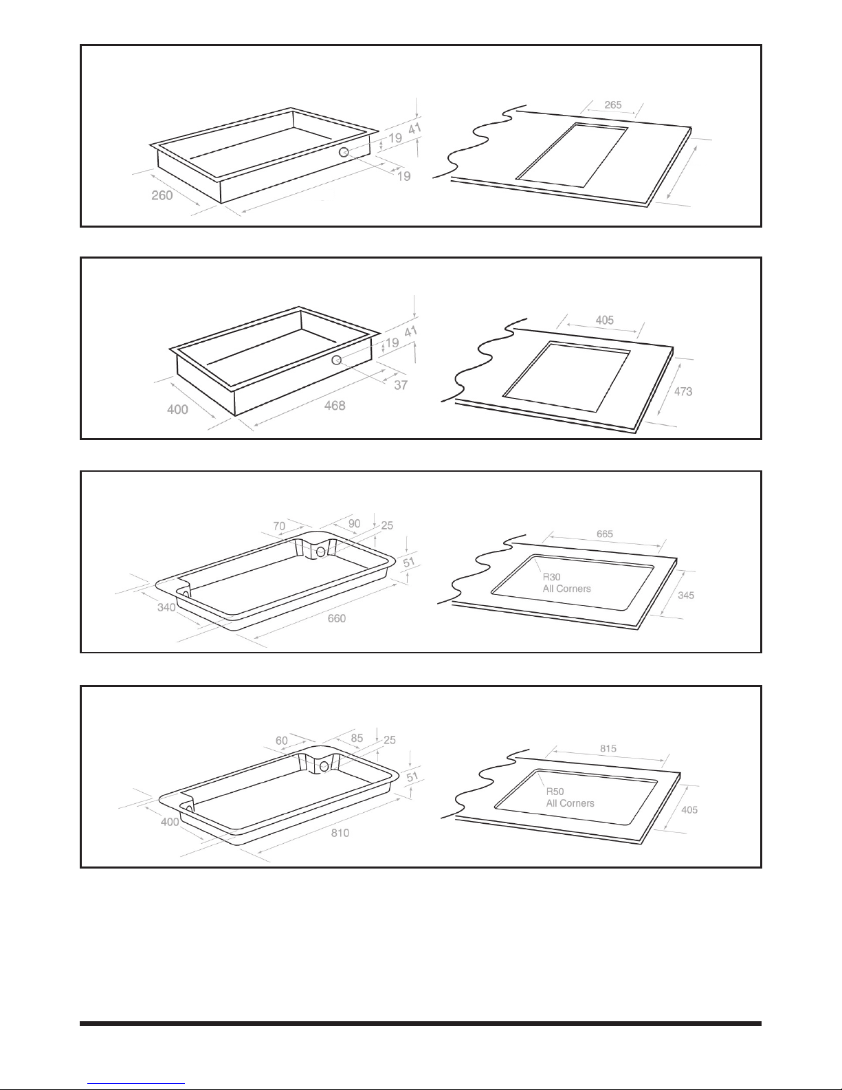
Model GL301N/GL301ND
Diagram A
Tray Dimensions (in mm)
Diagram B
Cut-Out (in mm)
Model GL302N/GL302ND
Diagram A
Tray Dimensions (in mm)
Diagram B
Cut-Out (in mm)
Model GL2N/GL2ND
Diagram A
Tray Dimensions (in mm)
Diagram B
Cut-Out (in mm)
Model GL3N/GL3SS
Diagram A
Tray Dimensions (in mm)
Diagram B
Cut-Out (in mm)
470
475
Page 3
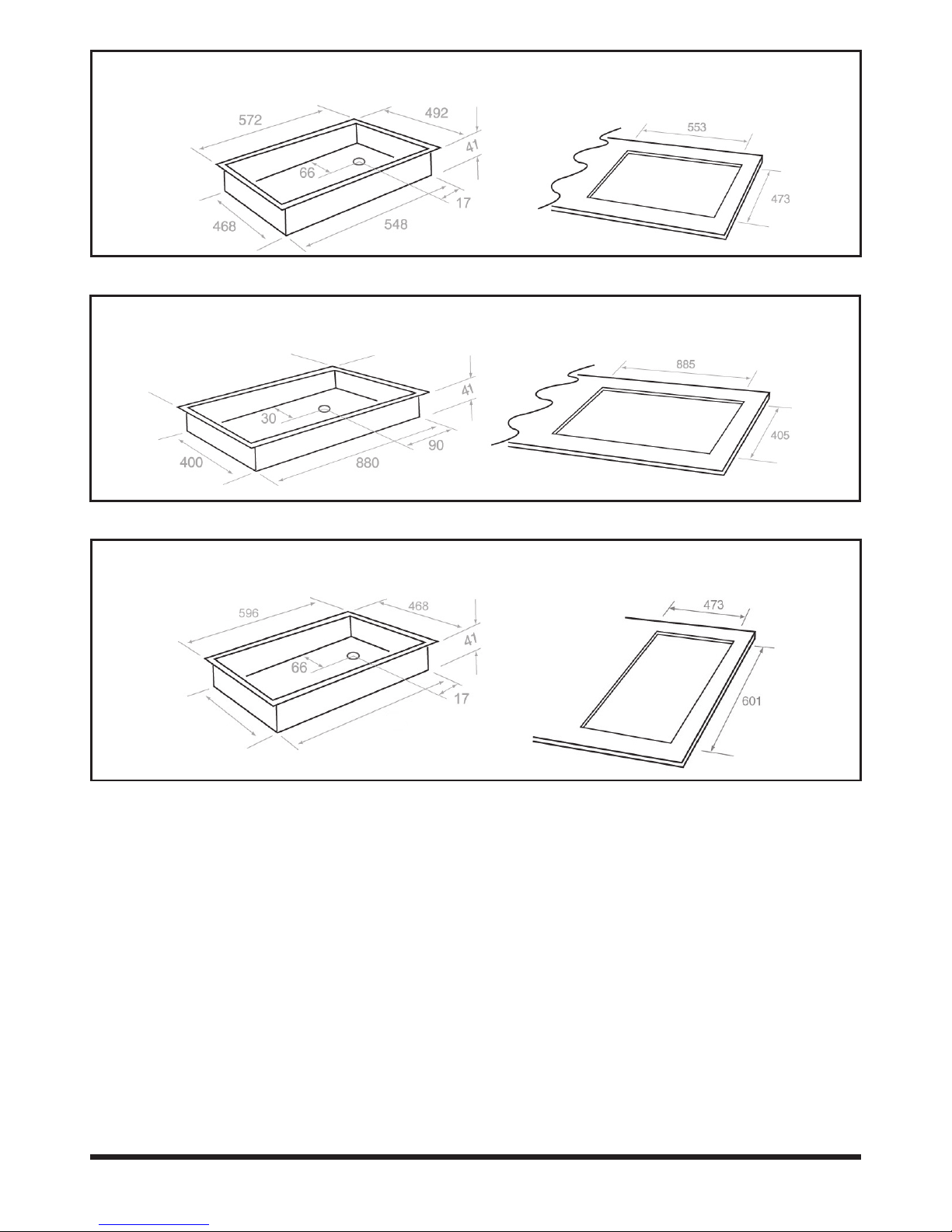
Model GL603N/GL603ND
Diagram A
Tray Dimensions (in mm)
Diagram B
Cut-Out (in mm)
Model GL4N/GL4SS
Diagram A
Tray Dimensions (in mm)
Diagram B
Cut-Out (in mm)
Model GL704N
Diagram A
Tray Dimensions (in mm)
Diagram B
Cut-Out (in mm)
Goldline N12- manual-ULPG Jan 2012
3
Page 4

Goldline N12- manual-ULPG Jan 2012
4
INSTALLATION INSTRUCTIONS
DATA PLATE DETAILS:
The data plate is located on the tray oor.
CHECK THAT THE DATA PLATE SHOWS THAT THE APPLIANCE IS SUITABLE FOR THE
AVAILABLE GAS SUPPLY. IMPORANT: VERIFY GAS TYPE WITH LOCAL GAS NETWORK
OPERATOR BEFORE CONNECTION OF THIS APPLIANCE.
1. Room Ventilation
This cooktop must be installed in a room that has permanent ventilation to effect
the correct operation of the appliances and also to provide adequate ventilation.
This airow must exceed 20m³ via permanent vented openings in the walls of the
room and these must have a section of 100cm² minimum. They must be constructed
in a manner so as to avoid any possible blockages. The airow can also be drawn
indirectly from an adjacent room provided it complies with any local regulations to
vent any fumes outdoors.
Not for use in Marine craft, caravans or Mobile homes unless
tted with safety device.
2. Before installing the appliance check that the location provides the required
clearances from combustible materials and if necessary provide protection to adjacent
surfaces as required by the regulations. Make provision for the gas supply to be
connected in the position shown in Diagram A.
3. Cut the opening in the bench top to the dimensions shown in diagram B.
4. Remove the hotplate from the carton.
Refer – Gas tting manual.
Position of gas inlet: See diagram on page 2. Depth from top of glass to bottom of tray:
70mm excluding regulator
5. Install the hotplate in the cut-out (see diagram B on page 2).
Note:
If clearance between side and rear walls and periphery of the burner is less than 250mm,
the walls must be protected with a non-combustible material. The protection must extend
a minimum distance of 450mm above the burner. Horizontal surfaces less than 750mm
vertically above the hotplate must also be protected.
6. Ensure that gas and electrical outlet are accessible with the appliance installed.
The gas connection to the regulator is 1/2” BSP. Please ensure gas supply line to
the appliance is of adequate length to allow sufcient withdrawal of appliance for
service or disconnection. The connection must be annealed copper pipe or exible
hose (if permissible by local authority).
7. In the event that exible hose is being used:
- The exible hose must be certied to AS/NZS1869 - class B or class D.
- The gas connection point must be between 800 to 850mm above the oor and in the
region outside the width of the appliance to a distance of 250mm.
Page 5

Goldline N12- manual-ULPG Jan 2012
5
- Please ensure that the exible hose shall not kink, in permanent deformation
position, exposed to exceeding heat (more than what is certied) or subject to
abrasion.
- Please ensure the hose assembly is restrained from accidental contact with the ue
outlet of an under bench oven.
- To inspect and replace the hose regularly.
- The length of the exible hose must be kept to a minimum.
8. Use a spanner at the at area provided to hold the regulator rmly, when making
the join. Refer diagram below.
Pressure test point:
- This is provided in the gas regulator.
- Remove the screw; connect the hose from the pressure gauge.
- Turn on the gas to the large burner and manually light the burner.
- The pressure is shown on the data plate.
- To increase the pressure, loosen locking nut and turn clockwise.
- Disconnect gauge and replace test point screw.
10. Test the appliance:
- Depress each control knob and turn to full ame setting.
- The burner will ignite. Adjust control knob to desired setting. Normally, no adjustment
should be necessary.
Note:
The cook top must be installed with provision to allow the gas to be turned off and
disconnected for servicing and removal of the appliance as required from gas supply.
WARNING!
HOSE ASSEMBLY MUST BE RESTRAINED TO PREVENT ACCIDENTAL
CONTACT WITH THE FLUE OF AN UNDERBENCH OVEN.
9. Once they are tightened
securely, turn the gas on and
check for leaks using a soap
solution and brush around all
joints and connections.
Pressure test point for LP and ULP gas only.
Use the regulator provided for town and natural gas.
Page 6

Goldline N12- manual-ULPG Jan 2012
6
- If any problem occurs, refer to the servicing instruction of the faultnding chart.
11. Please make sure that gas supply connection is easily accessible for servicing or
other purpose.
12. Stick the second data label (which is provided in the box) at a place, which is
noticeable, e.g.: inside the cabinet door or the sidewall.
13. Instruct the user to keep the user instruction manual.
If any of the above procedures do not produce satisfactory results, the agent’s service
department should be consulted for more specialize assistance.
14. Please note that the cooktop is tted with the ame failure device that cuts off the
gas supply when burner ame extinguishes suddenly or abnormally in order to avoid
gas leakage.
CONVERSION TO UNIVERSAL LPG FROM OTHER TYPE OF GAS
1. Install the correct injector size for the boiler and wok venturi system.
(refer the injector size table)
2. Adjust the bypass screw for each burner approximately by half a turn
from fully
3. Replace the boiler ring to the type that does not have any inner
portholes.
WARNING:
- DO NOT SPRAY AEROSOLS IN THE VICINITY OF THIS APPLIANCE WHILE IT IS IN OPERATION.
- SOME PROPELLANT GASES CAN BREAK DOWN WHEN HEATED AND PRODUCE CORROSIVE
VAPOURS, WHICH WILL ATTACK SOME MATERIALS.
- ARTICLES, WHICH ARE MADE OF FLAMMABLE MATER SHOULD NOT BE STORED IN DRAWERS
OR CUPBOARDS IMMEDIATELY BELOW THIS APPLIANCE.
- THE SILICONE RUBBER GASKET SHOULD NOT BE REMOVED UNDER ANY CIRCUMSTANCES. IN
THE EVENT THAT ANY PROTECTIVE RUBBER GASKET IS DROPPED OFF OR DAMAGED, THE
CONSUMER SHOULD CEASE FORTHWITH THE USE OF THE UNIT UNTIL IT IS DULY RECTIFIED.
- DO NOT STORE ARTICLES WITHIN 50MM OF THE BOTTOM OF THE HOTPLATE CASING.
- DO NOT TOUCH SPARK IGNITOR WHILE LIGHTING THE BURNER.
- WHEN THE APPLIANCE IS INSTALLED IN A MARINE CRAFT OR IN A CARAVAN, IT SHALL NOT BE
USED AS A SPACE HEATER.
- DO NOT MODIFY THIS APPLIANCE.
WARNING!
NOT FOR USE IN MARINE CRAFT, CARAVANS OR MOBILE HOMES
UNLESS FITTED WITH SAFETY DEVICE.
Page 7

Goldline N12- manual-ULPG Jan 2012
7
SERVICING INSTRUCTIONS
MINOR ADJUSTMENT
Access to By Pass Screw
- Light the burner and turn to
minimum setting (marked small
ame).
- The ame should be stable on
minimum setting and should not
extinguish when passing from
maximum setting to low setting.
- If adjustment is necessary, remove
the control knob by pulling upward.
The bypass screw is accessible
via the control knob spindle. Turn
the bypass screw anti-clockwise to
increase the turn-down rate
Access to manifold, gas taps and burner
assembly
- Remove glass hob and control knobs.
- To remove gas cocks. Unscrew the locking nut
(between cock and burner). Remove screws, the
cock can now be removed from the manifold.
If access to the barrel is required, remove two
screws, which retain spindle to body. If lubricating
the mechanism use Regosine Moly LM or other
approved grease.
To replace electrode
- Remove screw from the clamp holding the
electrode and thermocouple and note the
adjustment setting height of each. Replace electrode
and then t clamp and screw.
FAULT ISOLATION CHART
FAULT CAUSES REMEDY
Burner will not light
1. Air in gas line
2. Blockage in line
3. Ignition not sparking
4. Flame failure device faulty
5. Check the battery
(applicable to DC version)
1. Purge gas line
2. Trace back and clear
3. Check lead and electrode
4. Replace thermocouple and test
5. Replace the battery
Burner lights back to
injector
1. Excessive lint up burner
mixing tube
2. Excessive gas pressure
1. Remove and clean burner
2. Check gas regulator pressure.
Adjust if necessary.
Burner has explosive
ignition
1. Excessive gas pressure 1. Check gas regulator pressure.
Adjust if necessary.
Ignitor not sparking
1. Electrode gap
2. Ignition connection
1. Check gap, adjust if not
between 4-5mm
2. Check connection to ignitor,
replace if faulty.
If any problem cannot be rectied please contact the agent in your state or the gas supply authority service department
or contact the product manufacturer.
WARNING!
DANGER 220 VOLTS 50Hz.
DISCONNET POWER BEFORE SERVICING UNIT
DO NOT MODIFY THIS APPLIANCE
Page 8

Goldline N12- manual-ULPG Jan 2012
8
OPERATING INSTRUCTIONS
The hob cooker is unique in its burner design and layout. It is tted with the ultra hi-speed
burners and one boiling burner. Whilst all three burners perform as general utility burner the
two outside burners are specically designed for wok cooking. They deliver up to one and
a half times the ame heat and spread compared to normal hi-speed burners. All burners
retain normal simmer cooking facilities. The widely spaced positioning of the burners allows
for the use of large woks.
IGNITION
This hotplate is equipped with electronic ignition to each of the three burners and is
operated by depressing the individual control knob and turning it a quarter turn anticlockwise.
MANUAL IGNITION
If there is no power to the appliance or your are is experiencing a power black-out, simple
strike a match or spark igniter next to the required burner and follow the instruction above.
Note: the ame safety system is independent of power and will still operate without a power source.
Should your cooktop fail to ignite after manual procedure has been followed then check to
see that the gas supply to appliance has not been shut off.
CONTROLS
The Hobcooker has the control knobs, which are situated, at the front of the glass plate. An
indicator motif advises which knob controls each burner. The ‘full-on’ and pre-set ‘simmer’
positions are indicated by a large and small ame graphic on the glass plate next to each
individual control knob.
BURNER OPERATION
1. Depress the required control knob anti-clockwise to the FULL-ON position.
2. When the burner has ignited, adjust the control knob to the required setting. Flame
adjustment is achieved by rotating the control knob further in an anti-clockwise fashion
BATTERY REPLACEMENT (applicable to battery ignition model)
1. Open the battery holder cover ap
2. Remove old battery
3. Replace with new 1.5 Volt “D” size battery noting correct polarity
4. Close cover ap
Page 9

Goldline N12- manual-ULPG Jan 2012
9
CLEANING
- Allow the hob cooker to cool before attempting to dismantle or clean it. The glass
plate is best cleaned with a cloth, using warm soapy water. Use of abrasive powders
and pastes should be avoided as far as possible, but when necessary use only a mild
abrasive. For removal of hardened grease, very ne steel wool, wetted and liberally
soaped, can be used.
- Caustic solutions, washing soda, aerosol spray cleaners, bleach and some biological
cleaners are detrimental to some surface nishes and care must be taken not to
apply them to the burner bodies and caps.
- Do not wash burner caps in a dishwasher.
- For ease of cleaning, remove spillage from the bowls as soon as possible. Control
knobs may be pulled off for cleaning beneath them, but take care not to allow water to
enter the holes in the glass plate.
- When re-assembling the spillage bowl always ensure that it is correctly located over
the spark electrode. Care should be taken to keep the electrode clean and avoid
damage to the porcelain insulator when removing the spillage bowl during cleaning.
- It is recommended that the appliance should be clean as describe above daily for
optimal performance and longer life expectancy.
- Wash spill bowl regularly and clean dirt and grease in a weekly basis.
- Inspect exible hose connection regularly for sign of frying or damage once at
least a year.
- Check the burner port regularly for blockage especially if there is occurrence of
spillage and clean them if necessary.
MAINTENANCE SCHEDULE
- It is recommended that to have the units serviced by an authorized person at least
once a year.
Page 10

Goldline N12- manual-ULPG Jan 2012
10
HINTS ON THE USE OF THE HOTPLATE
Utensils should always be placed centrally on the pan supports and over the burners.
Flames which extend beyond the bottom of utensils are wasteful and can damage or
overheat handles. Large diameter utensils (greater than 200mm in diameter) must not be
allowed to protrude beyond the perimeter of the hotplate, as this could cause overheating or
damage to the adjacent bench.
SAFETY HINTS.
Always turn panhandles to the side or back of the hotplate – not out into the kitchen where
they can easily be knocked. Do not wear loose tting garments while the burners are in
operation, due to the possibility of fabric ignition, which may result in personal injury.
MINOR TROUBLE SHOOTING.
Symptoms Please check the following:
NO IGNITION
1. Check if anything is obstructing the electrode metal tip.
2. If 240 AC: check if appliance is connected to electrical supply.
3. If 1.5V battery: check and replace battery if required.
NO GAS Check that the gas is turned on at the main meter.
BURNER FLAME NOT
BURNING EVENLY
Check the burner head is sitting evenly and that the slots in the
burner head are not obstructed. In the event that you are not
satised with the hotplate, the distributor in your State should be
consulted.
Note:
Should you still experience difculties with your Goldline cook top please contact the manufacturer at the address and
phone number provided in this manual.
Do not place anything, e.g. ame tamer, asbestos mat, between pan
and pan support as serious damage to the appliances may result.
Do not remove the pan support and enclose the burner with a wok
stand as this will concentrate the ame and deect the heat onto the
hotplate.
Do not use large pots or heavy weights which can bend the pan support
or deect the ame onto the hotplate.
Locate pan centrally over burner so that it is stable and does not
overhang the appliance.
Use only wok support supplied or recommended by the manufacturer of
the appliance.
Page 11

Goldline N12- manual-ULPG Jan 2012
11
RECOGNISING ABNORMAL OPERATION
Should you notice any of these symptoms,
- ame light back
- ame lift off from the burner ports
- popping or minor explosions sound
- appreciable yellow tipping ame
- objectionable odour
Turn off the unit immediately. Stop using the unit.
Call authorized person or contact the manufacturer.
WARNING
This Gas Hob can be supplied in either of two Models
220 VOLTS 50 HZ or 1.5v D.C. Battery pack.
Check the data label afxed to your unit to ensure the correct model has been supplied.
IMPORTANT:
ANY SERVICING TO THIS APPLIANCE MUST BE CARRIED
OUT BY AN AUTHORIZED PERSON.
SAFETY WARNING WHEN OPERATING WITH LP GAS:
WHERE THIS APPLIANCE IS INSTALLED IN MARINE CRAFT OR IN CARAVANS, IT SHALL
NOT BE USED AS A SPACE HEATER.
SPARE PARTS SERVICE CONTACT NUMBERS:
For spare part and technical support enquires please call
MANUFACTURER: A’VARD INDUSTRIES P/L.
ADDRESS: 58-60 Quantum Close, South Dandenong, Victoria 3175, Australia.
TEL: 61 3 9799 9660
FAX: 61 3 9799 9662
WEBSITE: www.goldlinecorp.com.au
e-mail: info@goldlinecorp.com.au
Page 12

Items Unit
Ignition - -
Type Reference D/A
Top plate material -
Glass Colour -
Glass Shape -
Nos. of hob -
Gas Type -
Heat input for burner kW
Left
(Mj/hr) Centre
Right
Flame failure device -
Gas pressure kPa
Gas inlet connection -
Tray depth mm
Side clearance from the periphery of
mm
each burner to any combustable surfa
ce
Clearance from base tray of cooker to
mm
its non-combustable material underneath
Dimension
Base tray WxD mm
Glass top WxDxH mm
Cut-out WxD mm
Net weight kg
Model number
GL2N
DC 1.5V 220V/240V
Battery 50Hz
D
8mm toughened
Australian Glass
Black/White
Curved
2
HKTown Gas
5.2 (18.72)
-
5.2 (18.72)
Yes
1
Screw-1/2 inch BSP
51
150
50
660 x 340
750 x 450 x 8
665 x 345
13
GL301N
DC 1.5V 220V/240V
Battery 50Hz
D
8mm toughened
Australian Glass
Black/White
Rectangular
1
NG LPG
-
4.2 (15.0)
Yes
1
Screw-1/2 inch BSP
43
150
50
260 x 470
300 x 500 x 8
265 x 475
9.5
GL302N
DC 1.5V 220V/240V
Battery 50Hz
D
8mm toughened
Australian Glass
Black/White
Rectangular
2
NG LPG
2.3 (8.0)
-
4.2 (15.0)
Yes
1
Screw-1/2 inch BSP
43
150
50
400 x 468
465 x 500 x 8
405 x 473
11.5
GL3N
DC 1.5V 220V/240V
Battery 50Hz
D
8mm toughened
Australian Glass
Black/White
Curved
3
HKTown Gas
5.2 (18.72)
2.7 (9.72)
5.2 (18.72)
Yes
1
Screw-1/2 inch BSP
51
150
50
810 x 400
860 x 460 x 8
815 x 405
16.5
GL603N
DC 1.5V 220V/240V
Battery 50Hz
D
8mm toughened
Australian Glass
Black/White
Rectagular
3
HKTown Gas
2.5 (9.0) x 2
-
5.2 (18.72)
Yes
1
Screw-1/2 inch BSP
40
150
50
550 x 470
640 x 500 x 8
555 x 475
13.8
GL4N / GL4SS
DC 1.5V 220V/240V
Battery 50Hz
D
8mm toughened glass
or Stainless steel .
Black , White or Stainless steel
Rectagular
4
NG LPG
2.5 (9.0) x 2
-
5.2 (18.72) x 2
Yes
1
Screw-1/2 inch BSP
40
150
50
880 x 400
930 x 450 x 8
885 x 405
18
SPECIFICATION TABLE
Design and specification may change due to product improvement. No prior notice will be given. If there are any
queries, please feel free to contact our service center.
Please refer to the English version of this manual as the standards.
GL704N
DC 1.5V 220V/240V
Battery 50Hz
D
8mm toughened
Australian Glass
Black/White
Rectagular
4
NG LPG
2.5 (9.0) x 2
1.7 x1
5.2 (18.72) x 1
Yes
1
Screw-1/2 inch BSP
40
150
50
596 x 468
640 x 520 x 8
601 x 473
18
 Loading...