

Goldline GL-235-LV, GL-235-LV-HV Installation & Operation Manual
G
GLL--
2
2
3
3
5
5
Solar Pool Heating Control
M
Automatically Maximizes Solar System
Heat Collection
M
Precise Calibrated Temperature Setting Dial
M
Single Model Handles all Systems-Old or New
Pools, Spas, 12 or 24VAC Actuators.
M
Automatic Switch Over from Solar Heating to
Nocturnal Cooling if Desired
M
Standard 120/240 VAC 50/60 Hz. Input
& 12 and 24 VAC Output
M
Goldline’s Proven Reliability and Performance
M
Industry’s Only 5-year Limited Warranty*
M
Goldline Combo (GLC)
is GL-235 LV or GL-235 LV-HV
Control, Diverter Valve, Actuator & Sensors
Unique 5 Year Warranty*
*Refer to Limited Warranty Statement for Details.
Corporate Office:
42 Ladd Street
East Greenwich, RI 02818
(401) 884-6990
(401) 885-1500 Fax
Western Regional Office:
7171 Alvarado Road, Suite 104
La Mesa, CA 91942
(619) 462-4298
(619) 462-4498 Fax
Description
The GL-235 is designed to meet the need for easy installation,
dependable operation, and serviceability. The GL-235 incorporates unique, microprocesser based construction to ensure reliability and accurate performance. The GL-235 offers advanced
operating features to provide differential temperature control,
selectable high limit, programmable recirculation freeze protection, nocturnal cooling and optional booster pump control.
AUTOMATIC HEATING: If the collectors are warmer than the
pool water by 4Nor more, and the pool is below the selected
desired temperature, the valve will rotate allowing heat collection.
This heat collection will stop when the solar sensor falls to within
1.5NF of the pool temperature or the pool temperature exeeds the
“desired temperature” set on dial.
AUTOMATIC COOLING: (Field selectable option) If the collectors are cooler than the pool water by 6NF or more, and the
pool is above the selected desired temperature, the valve will
rotate allowing cooling via the solar collectors. The heat dissipation will stop when the collectors rise within 3NF of the pool temperature or the pool temperature is lowered below the set desired
temperature.
SINGLE SETTING FOR DESIRED TEMPERATURE: The
GL-235 logic is set by a single dial adjustment with the desired
pool/spa temperatures clearly indicated. The dial is calibrated
with the temperatures from 70NF to a high of 104NF for quick and
easy, user-friendly operation. The temperature set indicates set
pool/spa temperature, and the GL-235 will automatically dete
r-
mine if the water should be solar heated or cooled, thus maxi-
mizing the system capabilities.
TERMINAL STRIP CONNECTIONS: For input power, and
sensor inputs. Controls also have industry standard 3 pin connectors for both forward and reverse valve actuator operation and
screw terminal connectors.
LED INDICATORS: Show the status of the system operation,
Four highly visible LED’s show 1) power to the control, 2) power
output directing valves and/or pump to collect heat (heating), 3)
power output directing valves and/or pump to dissipate heat
(cooling), 4) sensor fault indicator shows sensor(s) not operating
properly.
GL-235 VALVE OUPUT: Rating is the industry standard 24
VAC. A jumper switches the output to 12VAC for compatibility
with older valve actuators. Output is fuse protected.
RECIRCULATION FREEZE PROTECTION: (field selectable
operation) turns the GL-235 output ON, directing warmer
pool/spa water through the collectors when near freezing temperatures are reached at the collector sensor. The GL-235 will allow
recirculation when the collector temperature rises to 42NF. Two
10K Ohm sensors are required for operation. One or more freeze
snap switches are recommended if freeze recirculation protection
is utilized. Important--see installation instructions before using
Recirculation Freeze.
SYSTEM TEST SWITCH: Allows the user to manually override the automatic function of the GL-235 and verify operation.
AAmmeerriiccaass
##11 BBeesstt SSeelllliinngg SSoollaarr CCoonnttrroolllleerr
AAmmeerriiccaass ##11 BBeesstt SSeelllliinngg SSoollaarr CCoonnttrroolllleerr
‘
‘
G
GLL--
2
2
3
3
5
5
Solar Pool Heating Control
Corporate Office:
42 Ladd Street
East Greenwich, RI 02818
(401) 884-6990
(401) 884-1500 Fax
Western Regional Office:
7171 Alvarado Road, Suite 104
La Mesa, CA 91942
(619) 462-4298
(619) 462-4498 Fax
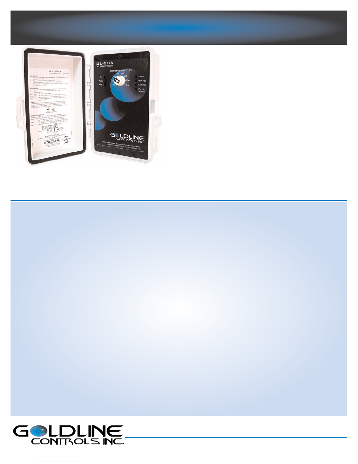
Model GL-235-LV-HV
The model GL-235-LV-HV has two outputs: 1) Selectable low voltage output for 12/24 VAC valve actuator. Wire via 3 pin connectors
or terminal block (compatible with older actuators). 2) Isolated contact, high voltage output for 120/240 VAC booster pump or time
clock override. Order sensors and freeze snap switches separately.
Model GL-235-LV
The GL-235-LV is similar to the GL-235-LV-HV, but has a low voltage output only.
Temperature Sensors
All Goldline temperature sensors are 10K Thermistors which are
accirate to +/- 2NF. The sensors are double-dip potted in silicone for
maximum protection from moisture.
PC: Multi-purpose sensor that can be used for both Solar (surface
mount) or Pool/Water (drill-in plastic piping).
SC-1/4: Brass screw-in sensor with 3” NPT pipe thread. Screws
directly into drain plug on the pump strainer basket.
Freeze Snap Switches
Goldline recommends the use of one or more freeze snap switches to
be wired in series with the solar sensor if the recirculate freeze protection feature is being used. Both snap switch models operate identically, however, the GC-1 is designed to meet the highest aerospace &
military specifications.
GC-1: Opens at 44N+/- 4NF, closes at 54N+/- 5NF (premium)
GC-2: Opens at 44N +/- 4NF, closes at 54N+/- 5NF (standard)
5 Year Limited Warranty*
Goldline Controls offers a 5 year limited warranty on all soalr controls and accesories. This warranty covers the repair or replacement
of the control at no cost for the first 36 months. For years 4 and 5,
Goldline will charge a fee of up to 60% of the current list plus shipping charges for repair or replacement.
*SEE WARRANTY STATEMENT FOR COMPLETE DETAILS.
Service You Can Count On
Visit www.goldlinecontrols.com, or call (800) 343-0826 to speak
with a qualified technical support representative. Our technichians
can assist you in selecting the correct controls and sensors for your
system and help troubleshoot any problems after installation.
Goldline Combo (GLC)
The “GLC” package contains everything required to automatically
control most solar pool heating systems. The “GLC” provides the
industry’s #1 best selling control, valve, actuator, and sensors together in one box. The “GLC” makes inventory control easier, ensures all
parts arrive at the job site, and components remain protected in factory-fresh condition. The Goldline “GLC” consists of the GL-235-LV
or GL-235-LV-HV control, a 24 VAC actuator, a valve (see chart)
and 2 sensors (see chart). For GLC with the GL-235-LV-HV control
add HV after GLC in Model number.
MODEL
GLC-1P-A
GLC-1P-B
GLC-2P-A
GLC-2P-B
GLC-2NP-A
GLC-2NP-B
VA LV E
1.5”/2” positive seal valve
1.5”/2” positive seal valve
2”/2.5” positive seal valve
2”/2.5” positive seal valve
2”/2.5” non-positive seal valve
2”/2.5” non-positive seal valve
SENSORS
2 PC sensors
1 PC sensor, 1 SC-3 sensor
2 PC sensors
1 PC sensor, 1 SC-3 sensor
2 PC sensors
1 PC sensor, 1 SC-3 sensor
(HV-add HV after the GLC to make combo with GL-235-LV-HV)
Specifications
Power: 105-130VAC, .5A 50/60Hz.
or
192-250VAC, .3A 50/60Hz.
Output: Low Voltage
12/24VAC,20VA,1.7/.85A
3 pin connectors for both
forward and reverse operation
Model GL-235-LV-HV also has
terminal block connections
GL-235-LV-HV only:
SPST-NO isolated contact
115VAC, 1 HP
240VAC, 2 HP
Sensors: 2 required-thermistor, 10K @
25NC/77NF. (snap switches
recommended if recirculate
freeze protection is used)
On differential: 4NF
Off differential: 1.5NF
High Limit: 70-104NF selectable via
calibrated scale
Recirculate freeze: on at 40NF, off at 42NF
Nocturnal cooling: On when collector 6NF less than
pool and pool hotter than high
limit, off when collector 3NF
less than pool or pool cooler
than high limit
GL-235
Solar Pool Controller
Installation & Operation Manual
for models
GL-235-LV
GL-235-LV-HV
www.goldlinecontrols.com
888-921-7665
North Kingstown, RI USA
LDLINE
CONTROLS INC.
G

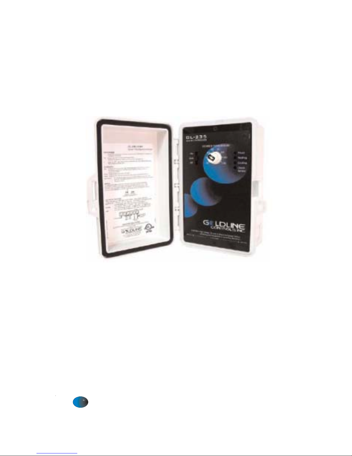
Installation
Mounting
The GL-235 is designed for outdoor use. Mount the box vertically with the knockouts facing
downward. For safety, the GL-235 must be a minimum of 5 feet (horizontally) from the pool or
spa.
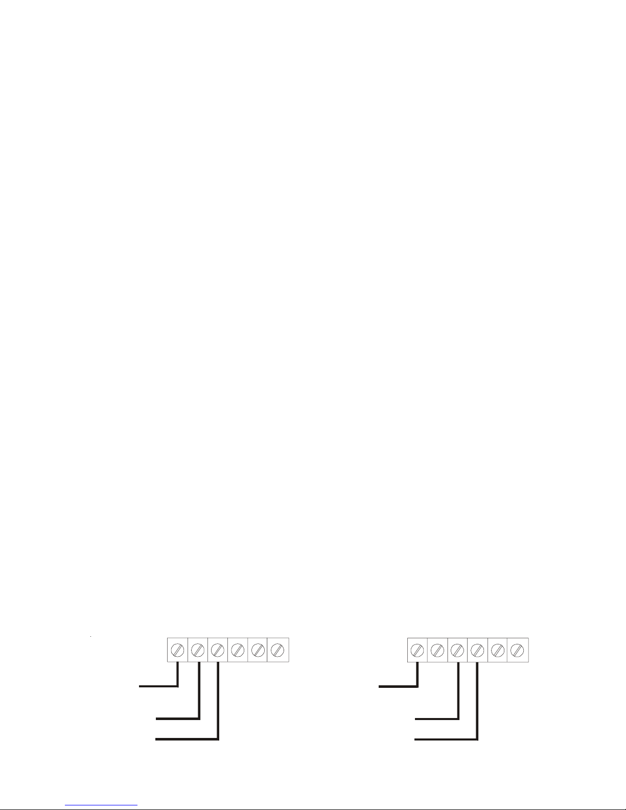
Power input
Turn off power at circuit breaker before wiring. Remove the internal panel to expose the wiring
connections. Either 115VAC or 240VAC can be used. Refer to the input wiring diagram (Figure 1)
on next page. WARNING: Applying 240VAC to the 120VAC input terminals will cause
permanent damage to the control.
Grounding
Refer to NEC and local codes for specific grounding requirements. In general, a separate ground
conductor must be run to the ground terminal on the pool service panel.
Low Voltage (LV) output: Solar Valve
The GL-235-LV and GL-235-LV-HV control a single valve. In most applications this is the solar
valve, which diverts water through the collector panels or through the normal pool loop depending
on conditions.
Description
The GL-235-LV and GL-235-LV-HV are differential temperature controls for solar heating of pools,
spas, and hot tubs. These models provide differential temperature control with an adjustable,
calibrated water temperature high limit. Automatic nocturnal cooling (for pools that overheat in
hot climates) and recirculate freeze protection functions can be enabled/disabled via internal jumpers.
Input power can be either 115 or 240 VAC. The output controls a 24VAC automatic valve actuator.
For older systems with 12VAC valves, an internal jumper can be moved to select 12 VAC output
operation. The GL-235-LV-HV has one low voltage output for controlling a single valve and a second
high voltage output for controlling a filter pump or booster pump.
Specifications
Power: 105-130VAC, .5A 50/60Hz.
Or
195-250VAC, .3A 50/60Hz
Output: Selectable low voltage 24VAC,
20VA, .85A or 12VAC, 20VA,
1.7A
GL-235-LV-HV only:
SPST-NO isolated contact
115VAC 1HP
240VAC 2HP
Sensors: 2 required (thermistor,
10Kohm @ 25C/77ºF).
Differential: on at 4ºF, off at 1.5ºF
Desired
Pool
Temp.: 70-104ºF calibrated scale or
Solar Off, 75-104ºF on
some models
Recirculate
freeze: On at <40ºF, off at > 42ºF
Enabled via jumper
Nocturnal
cooling: On when collector 8ºF less than
pool and pool hotter than limit,
off when collector 3ºF less than
pool or pool cooler than high
limit. Enabled via jumper
2
All controls are shipped with the output voltage set to the industry standard 24VAC. To use the GL235 with older 12VAC valves, move jumper J4, located on the right side of the circuit board.
The GL-235 provides two different types of connections to the pool/spa actuators. For older
actuators with no wire end connector, a 3 position terminal block is used. Connect the wires to the
proper terminal block according to the color code shown in Figure 4. If the valve operates opposite
to the way it is supposed to, reverse the red and white wires. Be careful not to short the valve output
wiring. The GL-235 is fused and shorting the output will require replacing the fuse.
For newer Goldline, Compool, Hayward, and Jandy actuators (with wire end connectors), two 3-pin
connectors are supplied. Plug the actuator into one of the two 3 pin connectors as shown in figures
2 or 3. If the valve operates opposite to the way it is supposed to, disconnect and plug into the other
connector.
High Voltage (HV) output: Booster Pump (model GL-235-LV-HV only)
The GL-235 can control a high voltage booster pump in addition to the normal low voltage solar
valve. Note the high voltage relay contacts are isolated so that the booster pump can be run on a
separate circuit, as required by many local codes. The GL-235 turns on, the valve output will operate
first, and then the HV relay will operate 30 seconds later.
High Voltage (HV) output: Timeclock Override (model GL-235-LV-HV only)
The GL-235 can also be used to override the filter pump timer. This is very important if recirculate
freeze protection or nocturnal cooling functions are being used. Also, this function can be used on
systems where the system should operate whenever solar heat is available, regardless of the timer
settings. The HV relay will operate approximately 30 seconds after the LV relay.
Sensor Mounting and Wiring
Most installations use a PC sensor to measure the pool temperature and another PC sensor to measure
the solar temperature. Alternatively, an SC-¼ sensor can be screwed into the pump strainer basket
to measure the pool temperature.
Pool Sensor: Drill a 3/8” (or 5/16”) hole in the PVC pipe. Remove burrs around the hole. Check
that the O-ring is seated on the PC sensor and then insert sensor into pipe. Tighten hose clamp over
the sensor to make a seal—DO NOT OVERTIGHTEN.
Solar Sensor: Use a screw or silicon adhesive to attach the sensor near the solar collector array.
The sensor does not have to be attached to the collectors. It is only important that the sensor be
exposed to the same sunlight as the collectors. Additionally, the underside of the sensing element
may be covered with silicon to minimize wind cooling.
Other 10K ohm Goldline sensors may be substituted. Wire should be twisted pair 20AWG. Sensor
wiring run outdoors must be rated for outdoor use and ensure that the wire connections are
protected from the weather. Do NOT run sensor wires in the same conduit or multiconduc-
tor cable as the valve actuator wires or any 120/240V circuit. For long runs or runs near
other electrical wiring use shielded cable (Belden 8428 for outdoor use). Ground the shields to the
GL-35/LV ground screw.
240 VA C
input power
115 VAC
input power
EARTH
GROUND
EARTH
GROUND
{
{
LV-HV
ONLY
LV-HV
ONLY
Figure 1
3
 Loading...