

Page 1

rok założenia
1992
OPERATING AND ASSEMBLY MANUAL
ELECTRIC TANKLESS WATER HEATER
FOR CENTRAL HEATING SYSTEMS
(Electric water boiler)
TYPE EKW -
AsDC-W
- AsDC-W
-
AsZN-W
-
AsB II
- AsD-W
AsZN-W
AsB II
GoldLine
AsD-W
Intelligent AntiStop system
ZŁOTY CERTYFIKAT
PRZEDSIĘBIORSTWO
ZŁOTY CERTYFIKAT
GRAND PRIX
EKO-BUD '97
FAIR PLAY
2001-2009
2001
2010
GoldLine
Page 2
2
Bolier EKW AsD
-
W
10
15
8
7 9 2
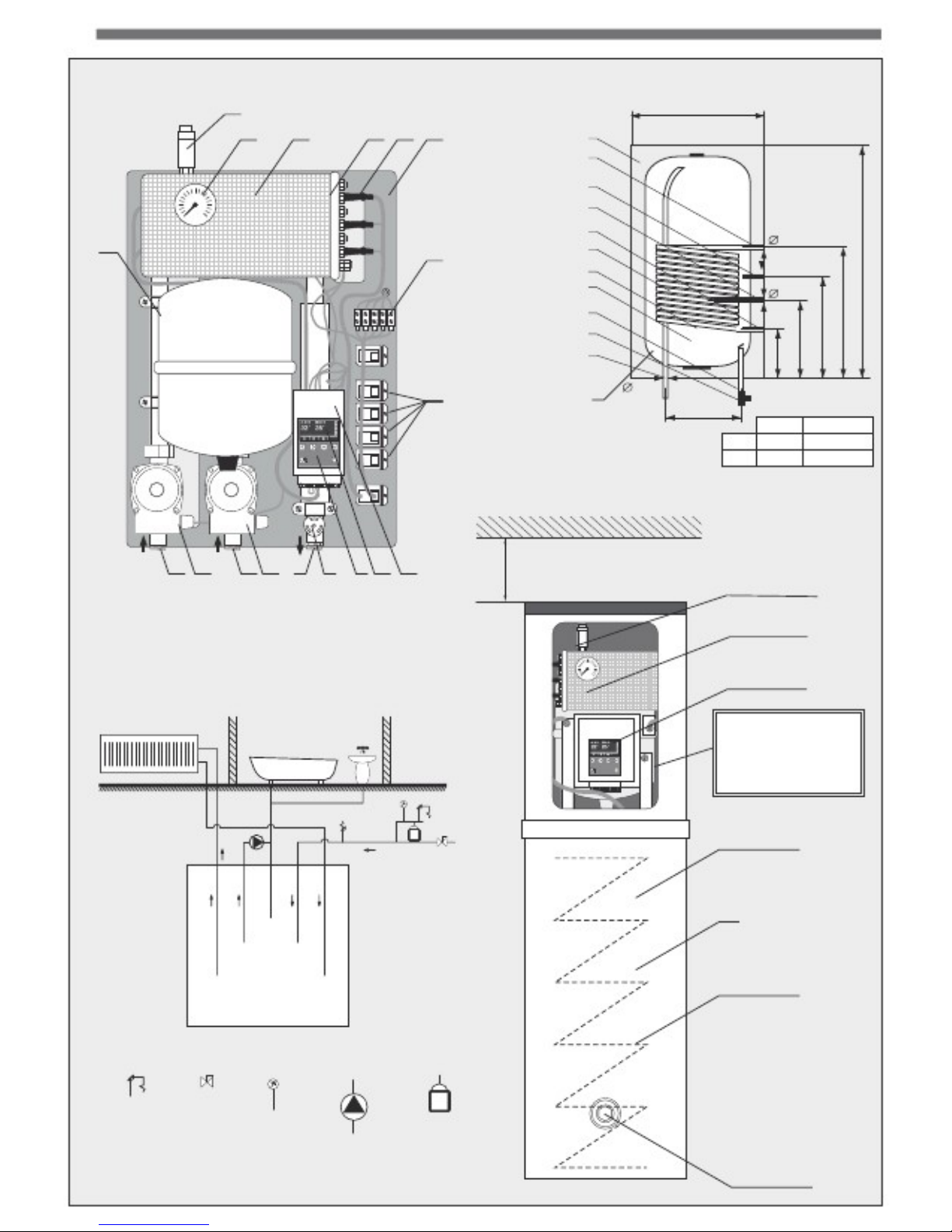
Insulation (polistyren)
CH hot water inflow
Circulation
Sensor cover
CH water outflow
Tank diagram
460 mm
18
11
Spiral coil
Thermostat sensor cover
Magnesium anode.
Cold water inflow
3/4"
L
400 mm
1/2"
325 mm
12
20
c
11:53:3312 05 2011 czw
c
123456
1/2"
100 mm
L
80 l 830 mm
100 l
975 mm
Net weight
50 kg 53 kg
ESC ON OFF
Boiler
EKW AsDC
-
W
RETURN RETURN SUPPLY
54 cm
14 17
21 19 13 16 5 4 3
Min
. Premises height
2,1m
(required while installation)
VENT
MANOMETER 4 BAR
Boiler
EKW AsDC
-
W
With build-in HUW tank
- exemplary application
c 11:5
3:3312 05 2011 czw c 123456
CONTROL PANEL
ESC ON OFF
INSIDE BOILER
:
- CH PUMP
- HUW PUMP
- 8l CH MEMBRANE VESSEL
- 2X ONE-WAY VALVE
100l HUW TANK
20
circulation
HUW
outflow
CH.
Cold water
outflow
CH
COIL 29 kW
Safety
valve
Ball
valve
manomet
e
r
circulation
pump
membrane
vessel
MAGNESIUM ANODE
200 mm
Safety valve)
HUW outflow
600 mm
Page 3
3
RELAYS
ESC
ON OFF
10
15
8
7 9 2
18
11
SENSORS
SENSORS
ELTERM
BODY. BAL. CH. HUW. ROOM. WEA..
EXTERNAL
REGULATORS
ATTENTION
THERMOREGULATOR
0 V!
6
5
4
3
2
1
Boiler
EKW AsZN
-
W
6
c
11:53:3312 05 2011 czw
c
123456
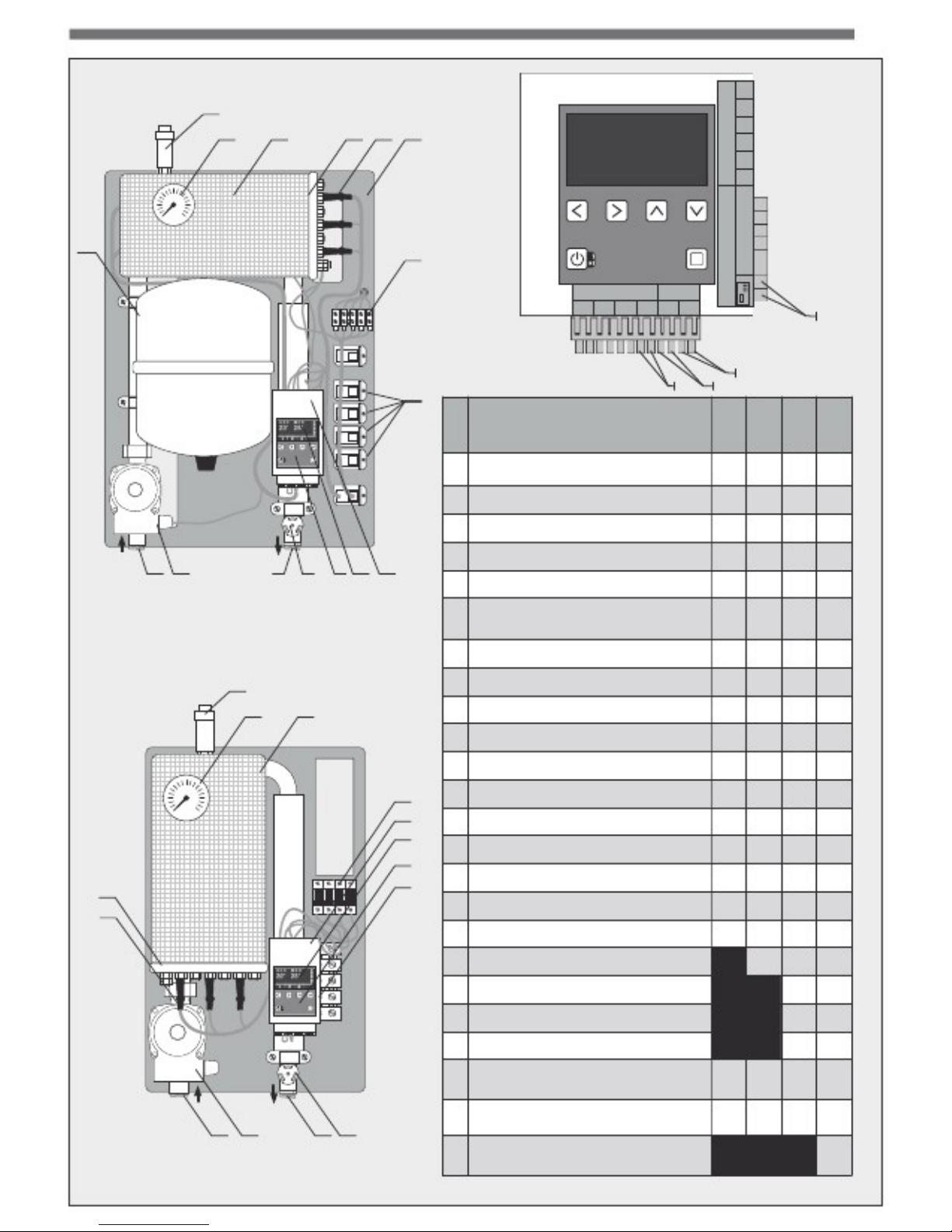
BOILER
EQUIPMENT
1
2 3 External casing
Mounting plate
Automatics mounting brackets
LCD display
Control panel
Room thermostat connection strip
Boiler body (tank)
Boiler insulation
Heating unit
ESC ON OFF
y
y y y y y y y y y y y y y y y y n
n
n
n
y
y
n
RETURN SUPPLY
4
16 5 4 3
14 17
13
5 6
Boiler
EKW AsB II
10
15
8
7 8 9 10
3/8”
automatic vent
11 Terminal strip
11
3
4
5
7
9
12
12
Relays
13
Feed stub pipe
3/4",
AsB II 1" 14
Return stub pipe
3/4",
AsB II 1" 15 Manomet
e
r 4 bar
16
Safety valve
3 bar 17 CH pump
(up to 48kW)
c
11:53:3312 05 2011 czw
c
123456
18 8 l membrane vessel
19 HUW pump
20 100l tank 21
Return stub pipe
¾’’
HUW 22 “Room” sensor terminal strip
23 „Floor” sensor terminal strip
24 HUW sensor terminal strip
ESC ON OFF
RETURN
SUPPLY
14 17
13 16 6
EKW
EKW EKW
AsZN . AsDC AsD
-W -W -W
12
24 22 23
EKW
AsBII
y y y y y y y y y y y y y y y y y y
n
n
n
y
y
n y y y y y y y y y y y y y y y y y y
y
y
y
y
y
n y y y y y y y y y y y y y y y y y y
y
y
y
y
y
y
Page 4
4
Thank you for placing trust in our company and for purchasing our product
. OPERATING AND ASSEMBLY MANUAL
- ELECTRIC TANKLESS WATER HEATER
FOR CENTRAL HEATING SYSTEMS
TYPE EKW AsZN-W, AsD-W AsDC-W, ASB II (Electric water boiler)
APPLICATION
All of the GoldLine (EKW AsZN-W, EKW AsD-W, EKW AsDC-W, EKW AsBII
) boilers are
designed to provide heating to small and medium sized locations equipped with
either open or closed low temperature (T<100°C) central heating water systems.
Boilers
EKW:
AsZN
-
W, AsD
-
W, AsDC
-
W in closed central heating system:
Boilers are designed for autonomous operation in both open and closed central
heating systems. Those boiler types come with a safety unit, 8l membrane vessel
and CH pump (*HUW pump in AsD-W and AsDC-W as well).
AsB
II 27 ÷ 48 kW
in closed central heating system
:
In closed heating system CH installation needs to be equipped in membrane vessel.
The membrane vessel is not supplied with the boiler.
AsB II
54 ÷ 144 kW
in closed central heating system
:
In closed heating system CH installation needs to be equipped in membrane vessel
and CH pump. The membrane vessel and CH pump are not supplied with the boiler.
TABLE OF CONTENTS
BOILER DESIGN
. . . .
. . . . .
.
. . .
. . . . .
2 HYDRAULIC AND
ELECTRICAL ASSEMBLY . .. . . . . . . . . 5
BOILER START
-UP
. . . . .
.
. . . . . ..
. . 7 SETTINGS
. . . . . . . .
. . . . . . . . . . .
. . . 8 REFERENCE DIAGRAMS
. . . . . . .
. . 17 DECLARATIONS OF CONFORMITY.
18
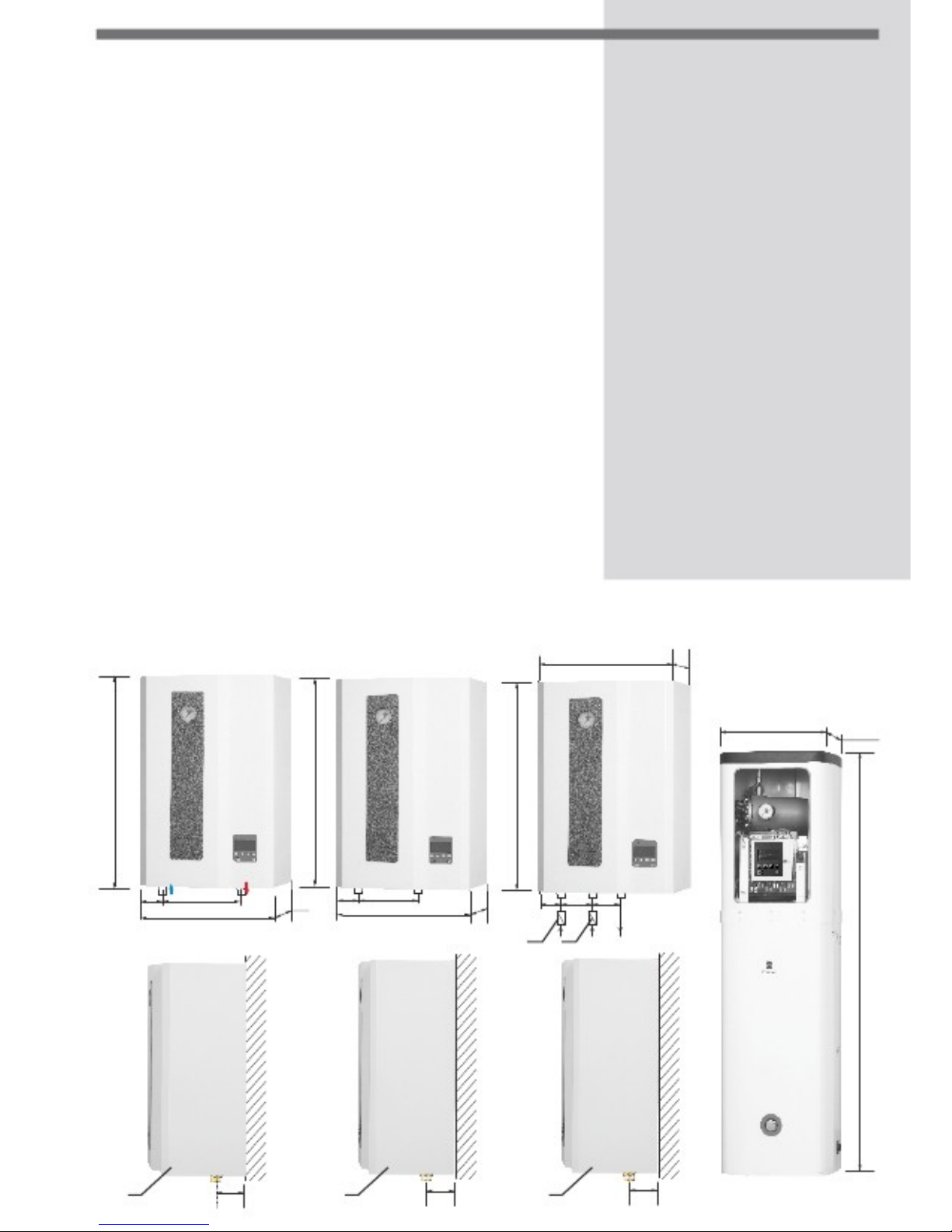
DIMENSIONS
: EKW AsB II
EKW AsZN
-
W EKW AsD
-
W
410
270
EKW AsDC
-
W
455mm 455mm
680
680
680
POWRÓT ZASILANIE
50
235
410
270
50
225
55
410
270
120 105
21 21
1
55
1
50
1
50
1560mm
Page 5
H
YDRAULIC
AND
ELE
CTRIC ASSEMBLY
HYDRAULIC ASSEMBLY
Please familiarize yourself with
the electrical and hydraulic diagram
, as
well as technical data prior to assembly. Details on www.elterm.pl
Boilers
EKW
AsZN
-W,
AsD-W, AsB II
are hanging vertical devices and should be
hung on bolts. First, remove the cuboidal casing (unscrew the sheet metal screw
at the bottom of the boiler).
HUW tank (supplied with AsD
-
W boiler) should as well be hung on bolts
. Boiler
EKW
AsDC
-W
is a standalone device
.
HUW tank is build
-
in into boiler.
I –
HYDRAULIC ASSEMBLY
A –AsZN
-W (¾” male thread half union for CH pump
– supplied with boiler
)
1. Feed stub pipe ¾” male thread – on the boiler’s right side (no. 13)
2. Return stub pipe ¾” female thread – on the boiler’s left side (no. 14)
B –
AsB II 27 ÷ 48
(
1”
male thread half union for CH pump
– supplied with boiler
)
1. Feed stub pipe 1” male thread – on the boiler’s right side (no. 13)
2. Return stub pipe 1” male thread – on the boiler’s left side (no. 14)
C – AsB II 54 ÷ 144
1.
Feed stub pipe
1” male thread
– on the boiler’s right side (n
o. 13)
2. Return stub pipe 1” male thread – on the boiler’s left side (no. 14)
D –AsD-W (¾” male thread half union
s for CH
and HUW
pump
s – supplied with boiler)
1. Feed stub pipe ¾” male thread – on the boiler’s right side (no. 13)
2. Return stub pipe ¾” male thread – on the boiler’s left side (no. 14)
3. Return stub pipe for HUW ¾” male thread – in the middle (no. 21)
5
EKW AsD
-W
BOILER
c
11:53:3312 05 2011 czw
c
123456
ESC ON OFF
ONE-WAY
VALVES
CH HUW SUPPLY
RETURN
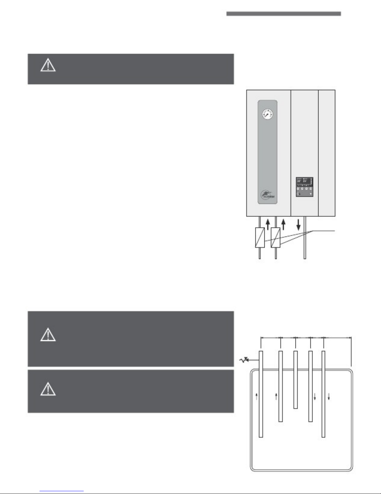
E –EKW AsDC
-
W All male threads
¾”
(top view
)
80 60 60 50 120
ATTENTION
!
Concerns AsD
-W
only One-way valves are mandatory while assembly
AsD-W boiler
.
Lack of
such valves on CH and HUW return causes inappropriate boiler and
pump operation as well as loss of guarantee.
One-way valves are not supplied with
boiler.
ATTENTION!
Concerns AsDC
-
W only
One-way valves for CH and HUW are factory assembled.
Safety valve is not included.
circulation
The boiler has to be connected to the central heating system
using the
¾” or
1”
pipe
unions according to the direction of water flow (arrows on boiler).
Connection to be
made in accordance with PN-91/B-02413 (open central heating systems) or
PN-91/B-02414 (closed central heating systems.). T
he central heating system has to be
flushed prior to start-up. If installed outside Poland, the boiler ought to be co
nnected in
accordance
with the applicable regulations valid in the country where the boiler is
installed
.
CH
HUW water
inflow
cold water
inflow
CH
Page 6

6
ELECTRIC ASSEMBLY
BOILER START
-
UP
Connection to the electrical system needs to be done in accordance with the regulations applicable
in
the
country where the given boiler is installed, and therefore must be done by qualified electrician (electrical
company installing the boiler puts a relevant stamp on the guarantee card). Heaters with powers from 4
to
24 kW are designed by an alternating current, 3-phase (400V3N~50Hz). 4, 6 and 9 kW
versions are also
available in 1-phase (230V1N~50Hz). In case 400V work is essential one should protrude bridge out of L1 L2 L3
clamp bar. Boilers AsZN-W, AsD-W and AsDC-W are equipped in TLZ terminal strip.
AsB II boiler is equipped
in switch disconnector. For this terminal strip one should connect power supply in accordance to L1 L2 L3
N PE
description. The technical data table (page 7) provides information on the cross-
section of the power cord to
be used for boiler connection and the applicable power (A) of the main fuses protecting the boiler.
Boiler
EKW
should be connected to the electric installation by a device enabling full power disconnection
. It is also
required to use residual current device (in case house installation lacks such).
A –
Connection strip
1 –
HUW measuring sensor
– concerns AsD-W boiler (no. 24)
0
VOLT !!!
ESC
ON
OFF
RELAYS
Sensors
ELTERM
Body. BALL. CH. HUW. ROOM WEATH
EKW
BOILER START
-
UP
2 –
room sensor
ELTERM (
optional
)
– clamps (no. 22)
3 –
„weather” sensor
(no. 23) 4 –
external room temperature controller
,
recommended
ELTERM’s „ThermLine RT” (no. 6)
Sensors
EXTERNAL
REGULATORS
6
5
4
3
2
1
THERMOSTATE
6
B –
„weather
” sensor connection
Weather sensor
no. 25
we do connect to boiler using 2
-
strand wire.
We connect it to the boiler by no. 23 strip, on weather sensor by no.
25A strip – connection order is irrelevant (2-strand wire is not
included to the boiler).
23 22 24
25 A
- weather
sensor
26 A
- room
sensor
C –
room sensor connection
(op
tional
)
Weather sensor no. 2
6 we do connect to boiler using 2
-
strand wire.
We connect it to the boiler by no.
22 strip, on weather sensor by no.
26A strip – connection order is irrelevant (2-strand wire is not
included to the boiler).
ATTENTION
:
Room and weather sensors are universal and exchangeable. One should remember about proper connection according
to points B and C above.
Page 7

BOILER START
-
UP
Elements
1 –LCD screen
2 – HUW signal icon
3 – HUW pump active icon
4 – HUW program active icon
5 – CH signal icon
6 – CH pump active icon
7 – CH program active icon
8 – current HUW temperature
9 – current CH temperature
10 – time
11 – data
12 – CH and HUW temperature setting icon
13 – floor heating icon
14 – room temperature icon (optional)
15 – weekday
16 – relays status
17 – function buttons
18 –ON/OFF + back button
19 – green diode – boiler turned on
20 – red diode – boiler turned off
21 – CHOOSE button
7
2 8 10
11
3 4 1 5 6 7 9 15
c
11:53:33
12 05 2011 THU
c
1
2
3
4
5
6
16 12
ESC
ON
14
OFF
18 13
20 19 17 21
TECHNICAL DATA
Power
4 kW 4 kW 6 kW 6 kW 9 kW 9 kW 12 kW
15 kW
18 kW
21 kW
24 kW
Manual power
distribution
100%
- 67% -
33% 100%
- 67% -
33% 100%
- 67% -
33% 100%
- 67% -
33% 100%
- 67% -
33% 100%
- 67% -
33% 100%
- 67% -
33% 100%
- 67% -
33% 100%
- 67% -
33% 100%
- 67% -
33% 100%
- 67% -
33% Modulation of Power Safety fuses (A)
Power cord Heated area Alternative
power supply (mm²) (m²) heating (m²)
by 1/3 by 1/3 by 1/3 by 1/3 by 1/6 by 1/6 by 1/6 by 1/6 by 1/6 by 1/6 by 1/6 1
phase
3
phase
s 1
phase
3
phase
s 1
phase
3
phase
s 3
phase
3
phase
s 3
phase
3
phase
s 3
phase
1 x 20
3 x 6 1 x 32
3 x 10
1 x 40
3 x 16
3 x 20
3 x 25
3 x 32
3 x 40
3 x 40
3 x 2,5
5 x 1,5
3 x 4 5 x 2,5
3 x 10
5 x 2,5
5 x 4 5 x 4 5 x 6 5 x 6 5 x 10
~ 50 ~ 50 ~ 70 ~ 70 ~ 110 ~ 110 ~ 150 ~ 180 ~ 220 ~ 260 ~ 300 ~ 70 ~ 70 ~ 100 ~ 100 ~ 150 ~ 150 ~ 210 ~ 250 ~ 310 ~ 360 ~ 400 5x35 5x50
5x50
5x50
5x70
5x95
5x120
AsB II boiler Manual power Power
Safety Power cord Heated area
(kW) distribution (V) fuses (A) (mm²) (m²)
EKW 27 9 ÷ 18 ÷ 27 400 3 x 50 5 x 16 220 - 380
EKW 30 10 ÷20 ÷30 400 3 x 50 5 x 16 240 – 400
EKW 33 11 ÷22 ÷33 400 3 x 50 5 x 16 260 – 450
EKW 36 12 ÷ 24 ÷36 400 3 x 63 5 x 16 280 – 480
EKW 39 13 ÷ 26 ÷39 400 3 x 63 5 x 16 290 – 500
EKW 42 14 ÷ 28 ÷42 400 3 x 80 5 x 25 300 – 520
EKW 45 15 ÷ 30 ÷45 400 3 x 80 5 x 25 320 – 570
EKW 48 16 ÷ 32 ÷48 400 3 x 80 5 x 25 340 – 600
AsB II boiler
Power
Safety Power cord
(V) fuses (A) (mm²)
EKW 54
EKW 60
EKW 66
EKW 72
EKW 96
EKW 120
EKW 144
400 400
400
400
400
400
400
3x100A
3x100 A
3x125 A
3x125 A
3x160 A
3x200 A
3x240 A
* Exact section should be matched by qualified electrician
**
Exact heated area depends on multiple factors
Page 8

8
3
SETTINGS
SETTINGS
ATTENTION
!!!! Boiler connected to the installation according to
point II ELECTRICAL
ASSEMBLY. CH (HUW) pump should be turned on for III speed. Valves on
radiators should be completely open while start-up.
1.
Red diode on
– no. 20,
boiler stand
-by –
boiler turned on
. 2.
For 5 s.
Press button:
Green diode no.
19
turns on.
JEZYK
POLSKI
ENGLISH
OK
JEZYK
POLSKI
ENGLISH
OK
LANGUAGE
LANGUAGE
3.
Choose language
POLSKI / ANGIELSKI (ENGLISH).
– choose
ENGLISH
– back to POLISH
– OK.
Confirm language selection.
4. On
LCD –
sign „
venting
+
progress bar”. One cannot skip this part. CH
(optionally HUW) pump turns on –
there is no possibility to disconnect
heaters. Those 5 minutes should be sufficient to vent
whole system
including boiler and pump. In case however another venting
is essential
please repeat previous step.
5. On
LCD –
information according to
description on page 7.
4
Venting
5
c
11:53:33
12 05 2011 THU
c
1
2
3
4
5
6
1
I –
INITIAL SETTINGS
:
1
CH and HUW
(concerns AsD-W and AsDC-W boilers only)
temp. setting
– press
1 time
,
enter function
: HUW
CH – go to CH setting
– get back to HUW setting
50 50
HUW
.
CH
50
50
CONTROL PANEL
ESC
ON
CH and HUW temperatures are set in the same way.
OFF
Page 9

SETTING
- press another time, below sign appears
: HUW
CH - decrease CH or HUW temp.
- in
crease CH or HUW temp.
- „
BACK
” (
given
parameters are
set
)
Multiple press enables getting back to main menu
9
HUW
50°C
50°C
DEFAULT: 50
CH
2
„Weather curve” setting
- press
1 time
,
enter the „weather curve” setting
- choose curve from
0 to 10
DEFAULT: 50
2
Weather curves operate for outside temperatures lower than
15°C.
To
make them work properly one should set CH temperature, e.g. 30°C and
choose curve number (1 – 10). Zero – no weather correction.
Meaning of values
:
Boiler keeps fixed CH temperature – the one we have previously chosen.
This temperature is then increased by weather correction value, i.e.
boiler’s temperature = set temperature + weather correction; where
correction factor depends on our choice.
For each grade below
15°C,
weather correction equals:
for 1 for 2 for 3 for 4 for 5 for 6 for 7 for 8 for 9 for 10
Examples
Weather curve set at
5,
boiler CH temperature:
30°C.
For outside temperature
higher than 15°C boiler will keep 30°C. For external temperature equal 5°C,
correction will estimate 10 x 0,5 = 5°C, thus boiler will maintain 35°C. For external
temperature equal - 5°C numbers will be: 20 x 0,5 = 10°C, boiler temp.: 40°C.
c
11:53:33
12 05 2011 THU
c
1
2
3
4
5
6
c
k:0
50 (+0 ) c
1
2
3
4
5
6
0,1°C
0,2°C
0,3°C
0,4°C
0,5°C
0,6°C
0,7°C
0,8°C
0,9°C
1,0°C
Boiler temp
80 70 60 50
40 30 K-=1 External temp.
20 10 0
-
10 -20 -30 K=5 K=10 Curves
1, 5, 10
for CH temp.
30°C
Page 10

10
3.
Room temperature setting on boiler (optional)
- press
1 time
,
enter the function
:
Room temperature
setting on boiler
- decrease CH or HUW temp.
(from
5° to
29°C)
- in
crease CH or HUW temp.
(from 6° to 30°C)
- „
BACK
” (
given temperatures are
set
)
Multiple press enables getting back to main menu
SETTINGS
ad. 3
c
11:53:33
12 05 2011 THU
c
1
2
3
4
5
6
c
k:19 c
25 c
1
2
3
4
5
6
I –
SETTINGS F
RO
M MENU
:
A.
SETTINGS
: 1. 2. 3. 4. 5. 6. 7. 8. 9. POWER
. . . . . . . . . . . . . . . . . . . 100 / 67 / 33%
SECTIONS
. . . . . . . . . . . . . . . . . . . .
CH and HUW
DATE
& TIME
. . . . . . . . . . . . . . . .
current
PID-P . . . . . . . . . . . . . . . . . . . 1
– 2 – 3 – 4 –
5 CH HISTERESE
. . . . . . . . . . . . 1
– 2 – 3 – 4 – 5 – 6
°C
HUW HISTERESE
. . . . . . . . . . . 1
– 2 – 3 – 4- 5 – 6
°C
DEF. SETTINGS
CONTROL
S ROOM
(OP
TIONAL
) . . . . . .
.
9 program
s CONTROL
s HUW
(OPTIONAL
) . . . . . . . . 9 program
s
ad. A1
SETTINGS
ENERGY CONSUM.
VENTING
POWER
SECTIONS
DATE & TIME
PID-P
CH HISTERESE
66
1
2
B.
ENERGY
CONSUMPTION
C.
VENTING
(CH and HUW
) Ad. A1. „
SETTINGS
–
POWER
”
EKW boiler
- press
1 time
,
SETTINGS sign appears
- press
2 times
,
POWER sign appears
- press another time
,
below sign appears
POWER
- decrease boiler power to
67%
or 33% - increase boiler power to
67%
or 100%
- „
BACK
” (
given
parameters are
set
)
Multiple press enables getting back to main menu
POWER
DEFAULT: 100
100%
POWER
DEFAULT: 100
Page 11

SETTING
ad. A2
11
SETTINGS
ENERGY CONSUM.
VENTING
Ad. A2.
„SETTING
S – SECTIONS ”
active
CH and HUW
. - press 1 time, SETTING sign appears
- press 2 times, SECTIONS sign appears
- (
to enter SECTION area press one time
button:
Another press shows below screen:
HUW
CH ON ON )
HUW
CH ON ON
- press
1 time
,
enter CH function
If we would like to turn off HUW, do not
press this function
- press another time
,
below
screen
appears
HUW
CH
(when we turn off CH function)
(when we turn off HUW function.)
ON ON
HUW
CH
ON
ON
- OFF –
section inactive
- ON –
section active
- „
BACK
” (
given
parameters are
set
)
Multiple press enables getting back to main menu
CH CH
ad. A3
Ad. A3.
„
SETTINGS
–
DATE & TIME
” - press
1 time
,
SETTING sign appears
- press
2 times
,
DATE
& TIME sign appears
(to enter press twice button on the right )
- press another time
,
below screen appears
Date, time and weekday
- change parameter
- change parameter’s value
- „BACK” (
given
parameters
are set
)
Multiple press enables getting back to main menu
SETTINGS
ENERGY CONSUM.
VENTING
POWER
SECTIONS
DATE & TIME
PID-P
CH HISTERESE
66
1
2
FRI
Page 12

12
Ad. A4.
„
SETTINGS
–
PID-P” –
proportional integral derivative controller
- press
1 time
,
SETTINGS sign appears
- press
2 times
, PID
-P
sign appears
(to enter press three times button on the right
- change parameter
- change parameter’s value
ATTENTION
:
In case boiler needs long time to achieve set temperature - set 4 or 5
In case boiler reaches set temperature to quickly – set 1 or 2
)
SETTINGS
ad. A4
SETTINGS
ENERGY CONSUM.
VENTING
- press another time
, PID
-P
function is visible
POWER
SECTIONS
DATE & TIME
PID-P
CH HISTERESE
66
1
2
- „
BACK
” (
given
parameters are
set
)
Multiple press enables getting back to main menu
PID-P
DEFAULT: 2
ad. A5
Ad. A5.
„
SETTINGS
–
CH H
I
STERES
E
” - p
ress 1
time
,
SETTING sign appears
- press
2 times
,
CH H
I
STERES
E sign appears
(to enter press four times button on the right)
- press another time
,
below screen is visible
CH H
I
STERES
E - decrease h
i
steres
e 1 – 2 – 3 – 4 - 5 - in
crease h
i
steres
e 2 – 3 – 4 – 5 – 6 - „BACK” (
given
parameters are
set
)
Multiple press enables getting back to main menu
SETTINGS
ENERGY CONSUM.
VENTING
6
POWER
SECTIONS
DATE & TIME
PID-P
CH HISTERESE
66
1
2
CH
HISTERESE
DEFAULT: 4
Page 13

SETTINGS
ad. A6
13
SETTINGS
ENERGY CONSUM.
VENTING
Ad. A6. „
SETTINGS
–
HUW
H
ISTERESE
” - press
1 time
,
SETTINGS sign appears
- press
2 times
,
HUW H
I
STERES
E sign appears
(to enter press five times button on the right)
- press another time
,
below screen is visible
HUW H
I
STERES
E - decrease h
i
steres
e 1 – 2 – 3 – 4 - 5 - in
crease h
i
steres
e 1 - 2 – 3 – 4 – 5 –
6 (
recommended
6) - „
BACK
” (
given
parameters are
set
)
Multiple press enables getting back to main menu
.
6
SECTIONS
DATE & TIME
PID-P
CH HISTERESE
HUW HISTERESE
1
2
4
HUW
HISTERESE
DEFAULT: 4
Ad. A7. „
SETTINGS
–
DEF. SETTINGS
” - press
1 time
,
SETTINGS sign appears
- press
2 time
,
DEF. SETTINGS sign appears
(to enter press six times button on the right
- press another time, below screen is visible
DEF. SETTINGS
- NO
- resigning from
default
settings
- YES - OK - approving
default
settings
- activating
default
settings
- HUW temperature
. . . . . . . . . 50°C
- CH temperature
. . . . . . . . . . . 50°C
- Bioler power
. . . . . . . . . .. . . . . 100%
- HUW sections
. . . . . . . . . . . . . . ON
- CH sections
. . . . . . . . . . . . . . . .
ON - PID-5 . . . . . . . . . . . . . . . . . . . . . . 3
- CH h
i
steres
e
. . . . . .. . . . . . . . . . 6
- HUW h
i
steres
e . . . . . . . . . . . . . 7
- „
BACK
” (
given
parameters are
set
)
Multiple press e
nables getting back to main menu
)
ad. A5
SETTINGS
ENERGY CONSUM.
VENTING
DATE & TIME
PID-P
CH HISTERESE
HUW HISTERESE
DEF. SETTINGS
1
2
4
DEF. SETTINGS
NO
YES
OK
DEF. SETTINGS
NO
YES
OK
Page 14

14 SETTINGS
WEEKLY PROGRAMMING ON BOILER
+ HUW TIME PROGRAMMING (OPTIO
NAL)
- are not a standard boiler equipment
Weekly programming on boiler, as well as HUW time programming
enables setting and maintaining
given temperature
at any defined time periods with minute accuracy. Limpid menu and illuminated
display makes the whole setting process easy. All previously selected parameters are memorized in
non-volatile boiler memory. Electronic processor can steer up to 9 programs, eac
h enables setting
requested temperature in any given time period.
1.
In case of two temperature ranges overlapping, the one with higher, more comfort temperature is
chosen.
2.
In case of a program overlapping with INITIAL SETTINGS (p
t.
I ad.1),
boiler wi
ll heat according to
chosen program variant.
Variant
I
II III IV V VI VII M
O TU WE TH FR MO MO M
O M
O M
O TU TU WE WE TU WE WE TH TH TH FR FR S
A S
A SU S
A TH FR FR WEEKDAY PROGRAMING
SA SU
SU SU SU
All days active
4
days active
3
days active
1 day active
(free choice
) Workdays active
Weekend
active
6
days active
1.
2.
3.
4.
5.
6.
7.
MO TU WE TH FR SA SU
–
weekdays
START – turn the program on
STOP – turn the program off
TEMP – settings from 20°C to 70°C
AKTYWNY – YES/NO
PROGRAM NO. – 1 to 9
FUNCTION BUTTONS
1
2
3
4
5
TU WE
START:
STOP:
TEMP:
ACTIVE:
TH FR SA SU
08:03
16:00 NR.
25 c
YES
6
ESC
ON
OFF
7
Page 15

SETTINGS
ad. A8
15
SETTINGS
ENERGY CONSUM.
VENTING
Ad. A8. „
SETTINGS
–PROGRAMS
ROOM
” (
OPTIONAL
) - press
1 time
,
SETTINGS sign appe
ars - press
2 time
,
PROGRAMS
ROOM
sign appears
(to enter press seven times button on the right)
- press another time
,
settings menu is visible
- change parameter
- change parameter’
s value
- „
BACK
” (
given
parameters are
set
)
Multiple press enables getting back to main menu
PID-P
CH HISTERESE
HUW HISTERESE
DEF. SETTINGS
PROGRAMS ROOM
1
2
4
TU WE
START:
STOP:
TEMP:
ACTIVE:
TU WE
START:
STOP:
TEMP:
ACTIVE:
ad. A8
TH FR SA SU
08:03
16:00 NR
25 C
YES
TH FR SA SU
08:03
16:00 NR
25 C
YES
Ad. A9.
„
SETTINGS
–PROGRAMS
HUW
” (
OPTIONAL
) - press
1 time
,
SETTINGS sign appears
- p
ress 2
time
,
PROGRAMS
HUW
sign appears
(to enter press seven times button on the right
)
SETTINGS
ENERGY CONSUM.
VENTING
- press another time, settings menu is visible
- change parameter
- change parameter’s value
- „BACK” (
given
parameters are
set
)
Multiple press enables getting back to main menu
CH HISTERESE
HUW HISTERESE
DEF. SETTINGS
PROGRAMS ROOM
PROGRAMS HUW
2
4
TU WE
START:
STOP:
TEMP:
ACTIVE:
TU WE
START:
STOP:
TEMP:
ACTIVE:
TH FR SA SU
08:03
16:00 NR
25 C
YES
tak
TH FR SA SU
08:03
16:00 NR
25 C
YES
tak
Page 16

16
ACTIVE
/ NONACTIVE PROGRAM
Each program can be temporarily deactivated
.
One should then turn in PROGRAMS ROOM or PROGRAMS HUW:
A
CTIVE
: N
O In case
we want to turn the program on
: ACTIVE: YES
SETTINGS
TU WE
START:
STOP:
TEMP:
ACTIVE:
TU WE
START:
STOP:
TEMP:
ACTIVE
:
TH FR SA SU
08:03
1 6 :00 NR
25 C
NO
TH FR SA SU
08:03
1 6 :00 NR
25 C
YES
Ad. A9.
„
ENERGY
CONSUMPTION
” - press
1 time
,
SETTINGS sign appears
- press
1 time
,
go to ENERGY
CONSUM.
- press 1 time, counters appear
- RST –
reset erasable counter
RESETABLE COUNTER
:
consumed energy in
kWh (
since
measurement start for max 24h). After 24h counter stops
autamatically.
LAST
24H:
counter shows actual energ
y consumption for the
last 24h – update every 20 min.
- „
BACK
” (
given
parameters are
set
)
Multiple press enables getting back to main menu
ad. A9
SETTINGS
ENERGY CONSUM.
VENTING
RES. COUNTER:
LAST 24h:
RST
Ad. A10. „
VENTING
”
1.
Function enables additional system
venti
ng without turning boiler off.
Proper system
vent
ing guarantees its proper operation, as well as preven
ts whole
installation from too quick wear.
2.
Additional possibility to check whether CH and HUW pumps operate properly.
ad. A10
SETTINGS
ENERGY USAGE
VENTING
- press
1 time
,
SETTINGS appear
- press
2 times
,
go to
VENT
ING function
Page 17

SETTINGS
- press
1 time
,
below screen appears
: HUW
CH
(
turn on HUW bleeding)
17
ON ON
HUW
CH
OFF
OFF
- press
1 time
–
go to HUW function:
OFF - press
1 time
–
turn on HUW bleeding:
ON Same method applies to CH installation
- After proper
vent
ing process, one should turn function off
: HUW
CH OFF OFF
HUW
HUW
- „
BACK” (
given
parameters are
set
)
Multiple press enables getting back to main menu
REFERENCE DIAGRAMS
Exemplary application of
AsZN
-W
boiler
(Max. Operation temperature 40°C)
AsZN-W boiler in floor heating instalation
AsZN-W as an independent heat source
AsDC-W boiler
With build-in HUW tank – exemplary diagram
AsZN-W boiler with HUW tank
- heating large quantities of water in short time
circulation
HUW
outflow
CH
Cold water
inflow.
CH
safety
valve
ball
valve
manomet
e
r
circulation
pump
membrane
vessel
Page 18

D
ECLARATION
OF CONFORMIT
Y
DECLARATION OF CONFORMITY
EC No. 1/2011
ELTERM M.M. KASZUBA SP.J. 86
-
200 CHEŁMNO UL.
PRZEMYSŁOWA 5
We herewith declare, under our sole responsibility, that the following products:
Tankless water
heater for central heating systems (electric central heating water boiler)
TYPE:
• EKW4As, EKW6As, EKW9As (~230V,50Hz, max power 4kW, 6kW, 9kW),
18
•
EKW4As, EKW6As, EKW9As, EKW12As, EKW15As, EKW18As, EKW21As, EKW24As, EKW27As, EKW30As, EKW33As,
EKW36As, EKW39As, EKW42As, EKW45As, EKW48As (3N~400V,50Hz, max power 4kW, 6kW, 9kW, 12kW, 15kW,
18kW, 21kW, 24kW, 27kW, 30kW, 33kW, 36kW, 39kW, 42kW, 45kW, 48kW)
• EKW-AsBII (3N~400V,50Hz, combined max power 54- 960kW, boilers’ cascade, each up to 48kW)
Models: AsPC, AsP, AsBN, AsZN, AsD, AsBI, AsZN-W, AsD-W, AsDC-W, AsBII
manufactured at the Elterm production plant,
are in conformity with the applicable provisions of the following EC Directives:
Directive no.
73/23/EWG
as amended
Title:
: Low Voltage Directive
(LVD) Electromagnetic Compatibility Directive
(EMC)
Directive on the restriction of the use of
certain hazardous substances in electrical and
electronic equipment (RoHS)
Directive on waste electrical and electronic equipment
(WEEE)
; GIOŚ reg. no.
: E0001767
89/336/EWG
as amended
Nr 2002/95/WE
as amended
Nr 2002/96/WE
as amended
and that the standards hereinafter referred to have been duly applied and observed. The last two digits of the year of the CE
marking application: 08. The harmonized standards applicable to the product to which this declaration of conformity pertains:
Number: PN-EN 60335
-
1 Issue
: Title
: :94+A11:95+A1:96+A12:96+A13:98+A14:98+A2:2000
Safety of household and similar elec
tr
ical appliances
+A15:2000+A16:2001:2004/A1:2005/A12:2006(U)
Particular requirements for tankless water heaters
Int
erference emission for household appliances
Interference immunity
Harmonic current emissions
Limitations of voltage fluctuations
Electromagnetic fields
- methods for evaluation
And measurement
:2002+A1
:1999+A1:2004
:2004 PN-EN 60335
-2-
35
:1998+A1:2000:2005/A1:2007(U)
PN-EN 55014
-
1 PN-EN 55014
-
2 PN-EN 61000
-3-
2 PN-EN 61000
-3-
11
:2000 PN-EN 50366
:2004+A1:2006(U)
Other documents or information required by the EC Directives:
Report n
o.
:
B-47/03
CLBT/ZR/67/2003
456/BS/EMC/04
BE/39/2006
BEM-66/07
B-71/07
Date:
24.06.2003
09.07.2003
27.04.2004
27.01.2006
17.10.2007
17.10.2007
Laborator
y
:
KEWA - ECO, Bydgoszcz
GP -
CLBT, Warszawa
PREDOM
- OBR, Warszawa
Laboratorium Elektrotechniczne PCBC S.A.
Laboratorium Badawcze Maszyn i Urządzeń J.N.B. EUROVITA Sp. z o.o.
Laboratorium Badawcze Maszyn i Urządzeń J.N.B. EUROVITA Sp. z o.o.
Maciej Kaszuba
Chełmno, 2011.05.07
Page 19

WE ALSO RECOMMEND
:
HYDRAULIC BALANCERS
SHE, SHE
-
SP, SHE
-
OC
from 25 to 420 kW
LEATHERETTE
COAT
PUR FOAM
0,025W/mK
HYDRAULIC BALANCERS
SHE-ELTERM
HYDRAULIC BALANCERS
SHE-SP ELTERM
WITH AIR SEPARATOR
HYDRAULIC BALANCERS
SHE-OC ELTERM INSULATED
PUMP MODULES WITH MIX SYSTEM
Boiler's pump module with mix system
ADVANTAGES
: - Boiler's return protection (against dew
effect)
- Required along with new solid fuel CH
boilers installation (guarantee terms)
- Pump work regulation according to
temperature differences (supply vs.
return) - (turns pump off when low
supply temp. occurs)
- In case there is no separate safety
pipe in CH, boiler will not be cut
off from open system vessel (as it
happens in case of 3- and 4-way
valves)
Floor heating's pump module with mix system
-
Floor area
- up to 120m²
,
- Possibility to link up two separate funnels
- Regulation from 2° to 50°C
Details on
www.elterm.pl
Page 20

Reccomended room temperature controllers:
ThermLine RT
Room temperature controllers
ThermLine RT
Pump temperature controllers
ThermLine PT
ThermLine RT
–
R (
air temp.
)
ThermLine RT–F (floor temp.)
ThermLine RT–RF (air-floor temp.)
ThermLine RT–RW (wireless air temp.)
ThermLine PT
-
P2
ThermLine PT-P3
ThermLine PT-P4
controlls CH or HUW pump
controlls HUW pump
controlls CH and HUW pump
Advantages of RT controller:
• Programming with accuracy of 1 min.
• 9 independent programs
• Actual temperature setting
• Accurate hysteresis - from +/- 0,1°C to +/- 1°C
• Removable steering panel (safe installation)
• Build-in installator mode
• 16A relay
• Non-volatile memory
Advantages of PT controller:
• LED display
• Intelligent Anti Stop system
• Anti-freeze
• Simple handling
Electric towel rails and bathroom hea
ters
ECO 70 ÷ 110 W
and ECOTERM 320 ÷ 800 W with stepless power regulation
Full offer on www.elterm.pl
rok założenia
1992
ELTERM M.M. Kaszuba SP.J.:86-200 Chełmno, ul. Przemysłowa 5, POLSKA,
tel. (0048) 56/686 93 05, 692 06 06, biuro@elterm.pl • www.elterm.pl
 Loading...