

Above-Ground Pool Automation
by
888-921-POOL
www.goldlinecontrols.com
LD
C
G
LINE
ONTROLS
Aqua TrolAqua Trol
Aqua TrolAqua Trol
Aqua Trol
®

IMPORTANT SAFETY INSTRUCTIONS
When using this electrical equipment, basic safety precautions should always be followed, including the following:
• READ AND FOLLOW ALL
INSTRUCTIONS
• Disconnect all AC power during installation.
• Warning - To reduce the risk of injury, do not permit
children to use this product unless they are closely
supervised at all times.
• A green colored terminal marked "Earth Ground" is
located inside the wiring compartment. To reduce
the risk of electric shock, this terminal must be connected to the grounding means provided in the electric supply service panel with a continuous copper
wire equivalent in size to the circuit conductors supplying the equipment.
• One bonding lug for US models (two for Canadian
models) is provided on the external surface. To
reduce the risk of electric shock, connect the local
common bonding grid in the area of the swimming
pool, spa, or hot tub to these terminals with an insulated or bare copper conductor not smaller than
8 AWG US / 6 AWG Canada.
• All field installed metal components such as rails,
ladders, drains, or other similar hardware within 3
meters of the pool, spa or hot tub shall be bonded
to the equipment grounding bus with copper conductors not smaller than 8 AWG US / 6 AWG
Canada.
• SAVE THESE INSTRUCTIONS

Table of Contents
OPERATIONOPERATION
OPERATIONOPERATION
OPERATION
The Aqua TrolThe Aqua Trol
The Aqua TrolThe Aqua Trol
The Aqua Trol
®®
®®
®
..........
..........
.......................................................................1
Water Chemistry....Water Chemistry....
Water Chemistry....Water Chemistry....
Water Chemistry.....................................................................1
Controls....................................................................Controls....................................................................
Controls....................................................................Controls....................................................................
Controls....................................................................6
Maintenance........................................................Maintenance........................................................
Maintenance........................................................Maintenance........................................................
Maintenance.................................................................8
.
INSTALLATIONINSTALLATION
INSTALLATIONINSTALLATION
INSTALLATION
Mounting....................................................................Mounting....................................................................
Mounting....................................................................Mounting....................................................................
Mounting....................................................................9
Plumbing..............................................................Plumbing..............................................................
Plumbing..............................................................Plumbing..............................................................
Plumbing.....................................................................10
Wiring..............................................................Wiring..............................................................
Wiring..............................................................Wiring..............................................................
Wiring.........................................................................11
TROUBLESHOOTINGTROUBLESHOOTING
TROUBLESHOOTINGTROUBLESHOOTING
TROUBLESHOOTING
Troubleshooting....................................Troubleshooting....................................
Troubleshooting....................................Troubleshooting....................................
Troubleshooting.............................................................13
WARRANTYWARRANTY
WARRANTYWARRANTY
WARRANTY
Warranty...........................................Warranty...........................................
Warranty...........................................Warranty...........................................
Warranty........................................................................15

1
OPERATION
The Aqua Trol® is an automatic chlorine generation system with a built-in filter
pump timer designed specifically for above ground pools. The operation requires a low concentration of salt (sodium chloride) in the pool water at levels
low enough that it normally will not be tasted. The Aqua Trol automatically
sanitizes your pool by converting the salt into free chlorine which kills bacteria
and algae in the pool through a process called electrolysis. Because chlorine will
revert back to sodium chloride after killing the bacteria, these reactions will continuously recycle virtually eliminating the need to add sanitizing chemicals to
your pool. The only time you may need to add more salt to the pool is when
water is replenished due to backwashing, draining, or splashing (not evaporation).
The Aqua Trol incorporates a built in timer to control the pool filter. This timer
insures that the proper daily filtration and sanitization occurs. The Aqua Trol is
designed to handle the purification needs of the average residential above ground
swimming pool of up to 18,000 gallons (67,500 liters). The actual amount of
chlorination required to properly sanitize a pool varies depending upon bather
load, rainfall, temperature, and the pool's cleanliness.
The Aqua Trol is available with several different options to allow for easy installation on a wide variety of above ground pools. The cell may be connected with
1½" - 1¼" flexible hose or to 2" rigid PVC pipe when the -HP option is ordered,
or the cell may be mounted directly to the pool return jet when the -RJ version is
ordered. Similarly, the electrical connections may be made via 120V/15A "straight
blade" linecord and receptacle (standard Aqua Trol version, no option designation) or may be made via a 120V/20A "twist lock" linecord and receptacle when
the -TL version is ordered.
AQ-Trol-HP "Straight blade" 120V/15A linecord/receptacle; 2" (51mm)
rigid PVC piping or 1½ - 1¼" (38-32mm) flexible hose
AQ-Trol-HP-TL "Twist lock" 120/20A linecord/receptacle; 2" (51mm) rigid
PVC piping or 1½ - 1¼" (38-32mm)flexible hose
AQ-Trol-RJ "Straight blade" 120V/15A linecord/receptacle; adapters for
return jet mounting
AQ-Trol-RJ-TL "Twist lock" 120V/20A linecord/receptacle; adapters for re-
turn jet mounting
Before installing this product as part of a saline water purification system in an
above-ground pool with an immediately adjacent natural stone patio/decking, a
qualified stone installation specialist should be consulted regarding the appropriate type, installation, sealant (if any) and maintenance of stone used around a
saline pool with electronic chlorine generator in your particular location and circumstances.
Water Chemistry
As with any pool, it is important that you maintain chemical makeup of the pool
water. The table on page 2 summarizes the levels that are recommended by the
5. "No Flow" LED illuminated
The Aqua Trol
chlorine. Check that the flow switch is plugged into the connector on the bottom
of the control unit and that the wire is not cut or damaged. Make sure you have at
least 12" of straight pipe before the flow switch. If there is adequate flow and the
LED is still on, check that the arrows on the flow switch (on top of hex) are
pointing in the direction of flow.
6. "Test Salt Level" LED illuminated or flashing
Take a sample of your pool water to your local Authorized Aqua Rite Dealer and
have the salt level tested. No salt test is completely accurate and the test results
may vary from the salt level on the Aqua Trol display. If salt level is low, add salt
according to chart on page 4.
7. "High Salt" LED illuminated
Check salt level in pool/spa. If salt level is too high, lower salt level by draining
some of the pool water out of the pool and replace with fresh water. Continue
until the salt concentration is at recommended levels.
8. "Inspect Cell" LED flashing
Inspect and clean cell according to directions on page 8. When done, press the
"diagnostic" button for 3 seconds to stop the "Inspect Cell" LED flashing.
9. "Inspect Cell" LED illuminated
Remove and inspect the cell for scale. If the cell is scaled, follow the directions
on page 8 for cell cleaning. If the pool has the proper amount of salt and the
"Inspect Cell" LED is still illuminated, the cell may be worn and need replace-
ment.
10. Possible causes of little or no free chlorine residual
- Aqua Trol switch in OFF position.
- Desired Level % adjustment setting is too low.
- Low stabilizer (Cyanuric Acid).
- Filter pump switched off or filter pump time too short (8 hours for average size
pools, more for large pools)
- Salt level too low (below 2500 ppm, Low Salt LED on).
- Salt level too high (High Salt LED on).
- Very warm pools increase chlorine demand--increase Desired Level % or filter
run time.
- Cold water (below 50F) causes Aqua Trol to stop generating (Generating LED
flashing).
- Excessive scaling on cell.
- High level of Nitrogen in pool water.
- "Yellow Out" or similar treatment recently used. Some yellow algae treat-
ments will use chlorine at a very high rate and deplete the residual free chlorine.
Manually shock the pool if indicated in the directions on the algae treatment. It
still may be a matter of days before the pool returns to "normal" and chlorine
tests will show the desired 1-3ppm free chlorine reading.
11. "-Pcb-" displayed and all 4 red/yellow LEDs are illuminated.
A possible Printed Circuit Board fault has been detected. Call for service.
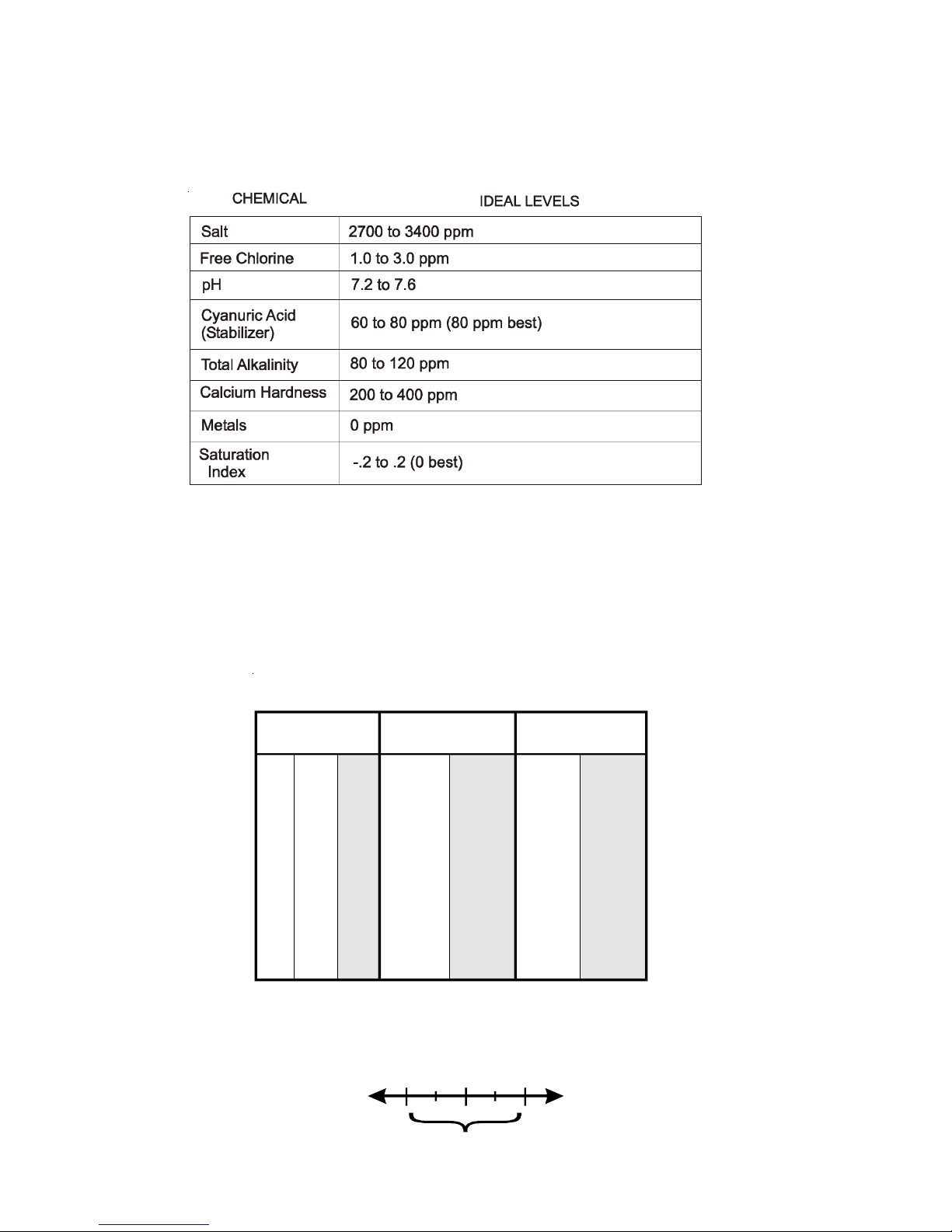
National Spa and Pool Institute (NSPI). The only special requirement for the Aqua
Trol is the salt level and stabilizer. It is important to maintain these levels in order
to prevent corrosion or scaling and to ensure maximum enjoyment of the pool.
Test your water periodically. Your local pool store can provide you with the
chemicals and procedures to adjust the water chemistry. Be sure to tell the pool
store that you are using an Aqua Trol
chlorine generator.
Saturation index
The saturation index (Si) relates to the calcium and alkalinity in the water and is
an indicator of the pool water "balance". Your water is properly balanced if the
Si is 0 ±.2. If the Si is below -0.2, the water is corrosive and plaster pool walls
will be dissolved into the water. If the Si is above +0.2, scaling and staining will
occur. Use the equation and chart below to determine the saturation index.
2
ºC ºF Ti
Calcuim
Hardness
Ci
To ta l
Alkalinity
Ai
53
60
66
76
84
94
103
12
16
19
24
29
34
39
.3
.4
.5
.6
.7
.8
.9
How to use: Measure pool pH, temperature, calcium hardness,
and total alkalinity. Use the chart above to determine Ti, Ci,and
Ai from your measurements. Insert values of pH, Ti, Ci and Ai
into the above equation. If Si equals .2 or more, scaling and
staining may occur. If Si equals -.2 or less corrosion or irritation
may occur.
Si = pH + Ti + Ci + Ai - 12.1
-.2
0.2
CORROSIVE SCALING
75 75
100 100
125 125
150 150
200 200
250 250
300 300
400 400
600 600
800 800
1.5 1.9
1.6 2.0
1.7 2.1
1.8 2.2
1.9 2.3
2.0 2.4
2.1 2.5
2.2 2.6
2.4 2.8
2.5 2.9
OK
3
Salt Level
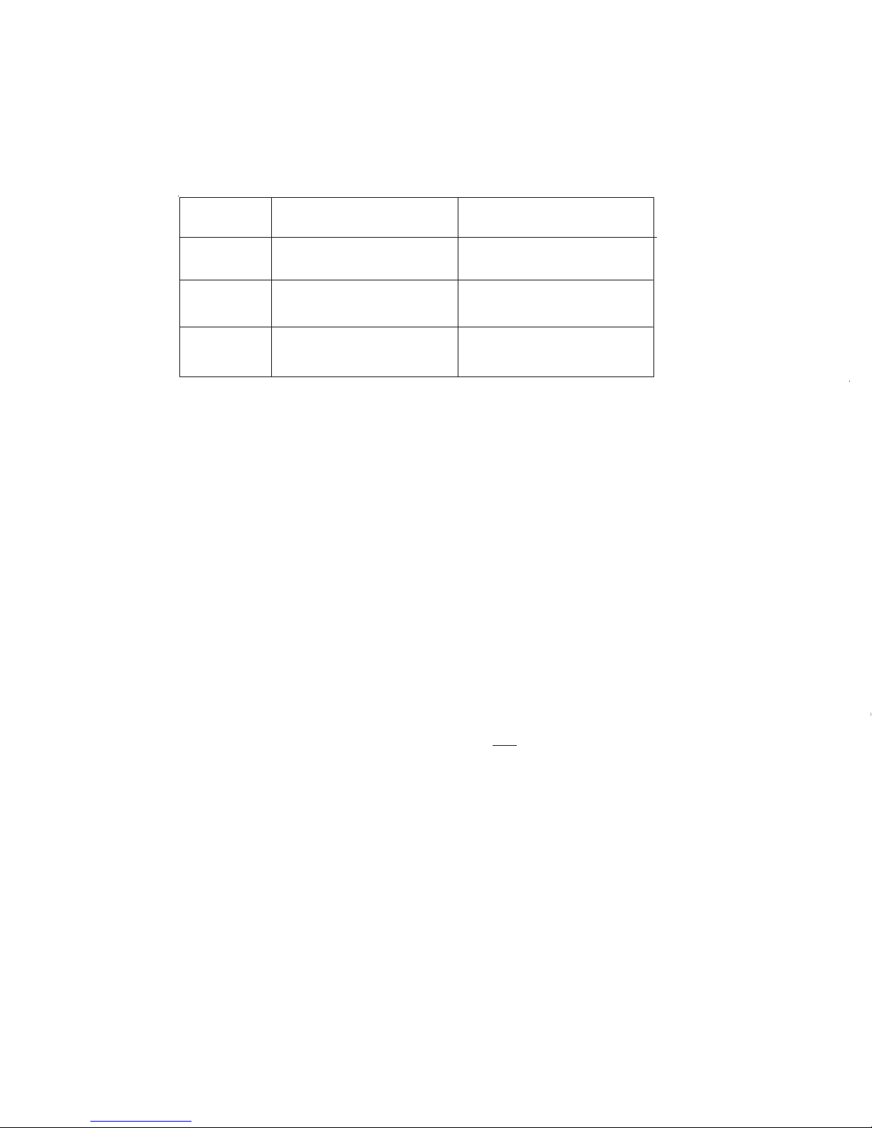
Use the chart on page 4 to determine how much salt in pounds (or Kgs) needs to
be added to reach the recommended levels. Use the equations below (measurements are in feet/gallons and meters/liters) if pool size is unknown.
The ideal salt level is between 2700-3400 ppm (parts per million) with 3200 ppm
being optimal. If the level is low, determine the number of gallons in the pool
and add salt according to the chart on page 4. A low salt level will reduce the
efficiency of the Aqua Trol® and result in low chlorine production. A high salt
level can cause the Aqua Trol to shutdown and may begin to give a salty taste to
your pool (generally, the salt will begin to be tasted at a level of about 3500-4000
ppm). The salt in your pool is constantly recycled and the loss of salt throughout
the swimming season should be small. This loss is due primarily to the addition
of water because of splashing, backwashing or draining (because of rain). Salt is
not lost due to evaporation.
Type of Salt to Use
It is important to use only sodium chloride (NaCl) that is 99% pure. This is
common food quality or water softener salt available in 40-80 lb. bags at your local
Goldline dealer. It is also acceptable to use water conditioning salt pellets, however, it will take longer for them to dissolve. Do not use rock salt, salt with more
than 1% yellow prussiate of soda, salt with more than 1% of anti-caking additives,
or iodized salt.
How to Add or Remove Salt
Turn the filter pump on and add the salt directly into the pool. Brush the salt to
speed up the dissolving process--to not allow the salt to sit in a pile on the bottom
of the pool. Run the filter pump for 24 hours with the suction coming from the
main drain (use the pool vacuum if there is not main drain) to allow the salt to
evenly disperse throughout the pool. The salt display may take 24 hours to respond to the change in salt concentration.
The only way to lower the salt concentration is to partially drain the pool and refill
with fresh water.
Gallons
Liters
(pool size in feet)
(pool size in meters)
Rectangular
Round
Oval
Diameter x Diameter x
Average Depth x 5.9
Length x Width x
Average Depth x 6.7
Length x Width x
Average Depth x 7.5
Diameter x Diameter x
Average Depth x 785
Length x Width x
Average Depth x 893
Length x Width x
Average Depth x 1000
Bonding
A lug used for bonding is attached to the bottom of the Aqua Trol enclosure.
Connect to the pool bonding system using minimum 8AWG copper wire if re-
quired by code.
Pump Output
The Aqua Trol's filter pump output is rated at 120 VAC, 15 A max. Check the
electrical rating marked on the pump motor. Connecting a pump with a higher
amperage rating may result in permanent damage to the Aqua Trol. The 120
VAC standard or twist lock pump receptacle is located outside, on the bottom of
the enclosure.
Electrolytic Cell and Flow Switch
The cell and flow switch plug into connectors on the Aqua Trol electronics unit.
Note that return jet units (-RJ option) will NOT have a flow switch. See diagram
below.
j
g
y
INPUT POWER
120 VAC linecord
to GFCI receptacle/breaker
 Loading...