

Goldline AQL-REMOTE-RF-PS-4, AQL-REMOTE-RF-PS-16, AQL-REMOTE-RF-PS-8 Installation & Operation Manual
Wireless Remote Display
for
Aqua LogicAqua Logic
Aqua LogicAqua Logic
Aqua Logic
Automation and Chlorination
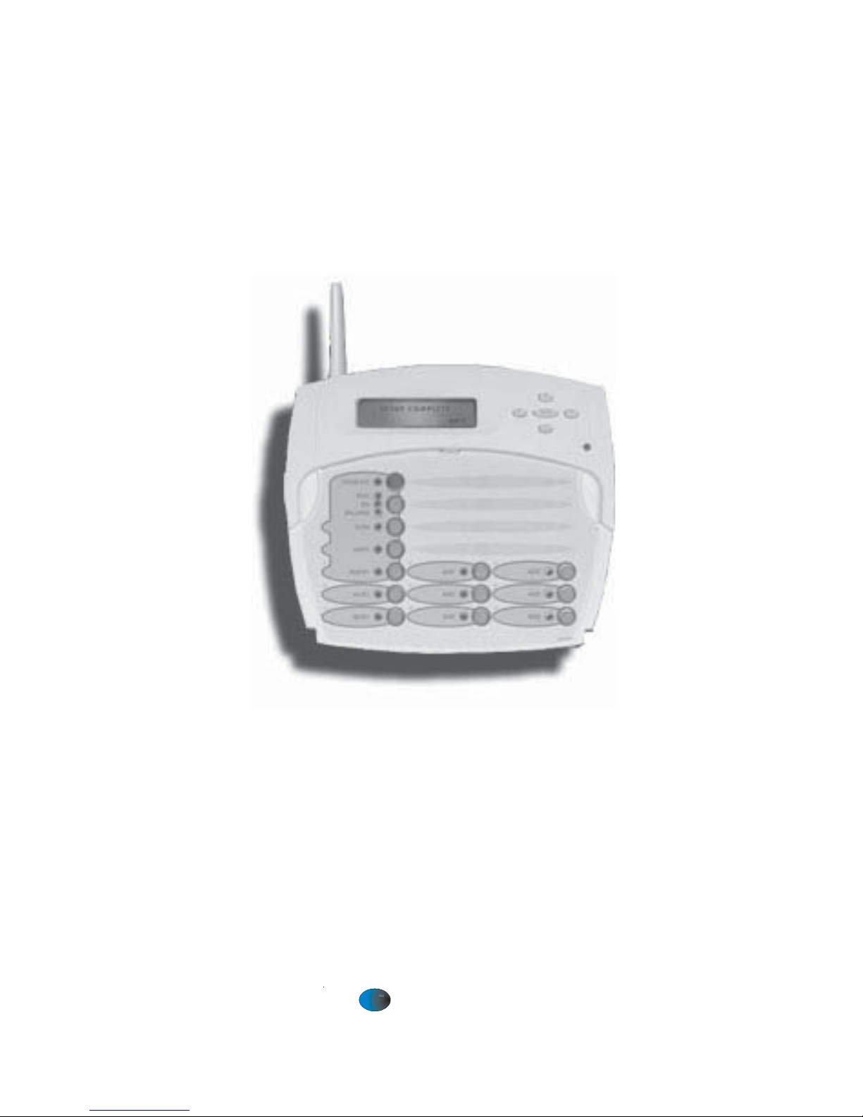
(model AQL-REMOTE-RF-PS-8 shown above)
Installation/Operation Manual
for model
AQL-REMOTE-RF-PS-4
AQL-REMOTE-RF-PS-8
AQL-REMOTE-RF-PS-16
LDLINE
CONTROLS INC.
G
www.goldlinecontrols.com

Compatibility
This product is compatible with all Aqua Logic controls operating with software
revision r2.00 or higher and Base Receivers with software revision r1.20 or higher . T o
verify the software level of your Aqua Logic control, press the Menu button (possibly multiple times) until “Diagnostic Menu” is displayed. Press the “>” or “<“ keys
(possibly multiple times) until the main software revision level is displayed (the revision should be 2.00 or higher). Next, press the ">" key (possibly multiple times) until
the "RF Base" revision level is shown (the revision should be 1.20 or higher).
If the software revision level is less than those specified above, contact the Goldline
T echnical Service Dept. from Monday through Friday, 8AM to 8PM Eastern at 888921-7665 for information on upgrades.
Installation
1. Base Receiver required: For operation of the wireless remote display/keypad,
the Aqua Logic control unit must have a base receiver (AQL-BASE-RF) installed. The receiver allows the Aqua Logic control until to communicate with
the spa-side remote.
2. Select Location: There are several considerations in choosing the location for
the wireless remote display/keypad:
Protected from the weather: The wireless remote display/keypad must be
mounted indoors or in a weather protected area (rain should never hit the
wireless remote display/keypad). The wireless remote display/keypad is
designed to mount onto a standard electrical utility box (same size as used
for a triple light switch) or can be mounted directly onto any wall surface.
Within range of Base Receiver: The wireless remote display/keypad must
be installed within 200 ft. (assuming the signal will have to travel through
walls) or 400 ft. (line of sight) from the Base Receiver which is typically
mounted on the Aqua Logic main control unit at the pool equipment pad.
The Base Receiver can also be mounted up to 500 ft. away from the main
control unit to shorten the distance between it and any wireless remote. See
the "Remote Mounting of the Base Receiver" section of the Base Receiver
manual for more details.
Near 120V wall outlet: The wireless remote display/keypad uses a plug-in
power supply with a 6 ft. cable.
3. Mount on wall: The wireless remote display/keypad must be mounted indoors
or in a weather protected area (rain should never hit the display/keypad). Refer
to the diagram on the following page.
a. Remove the wireless remote display/keypad baseplate from the cover by
lifting up on the cover at the lower end of the keypad.
b. Thread the wall mount power supply’s output connector from behind and
through the opening in the left side of the baseplate.
c. Screw the baseplate in the desired position (screws supplied by installer).
d. Plug the power supply’ s output connector into the mating connector on the
back of the wireless remote display/keypad.
1
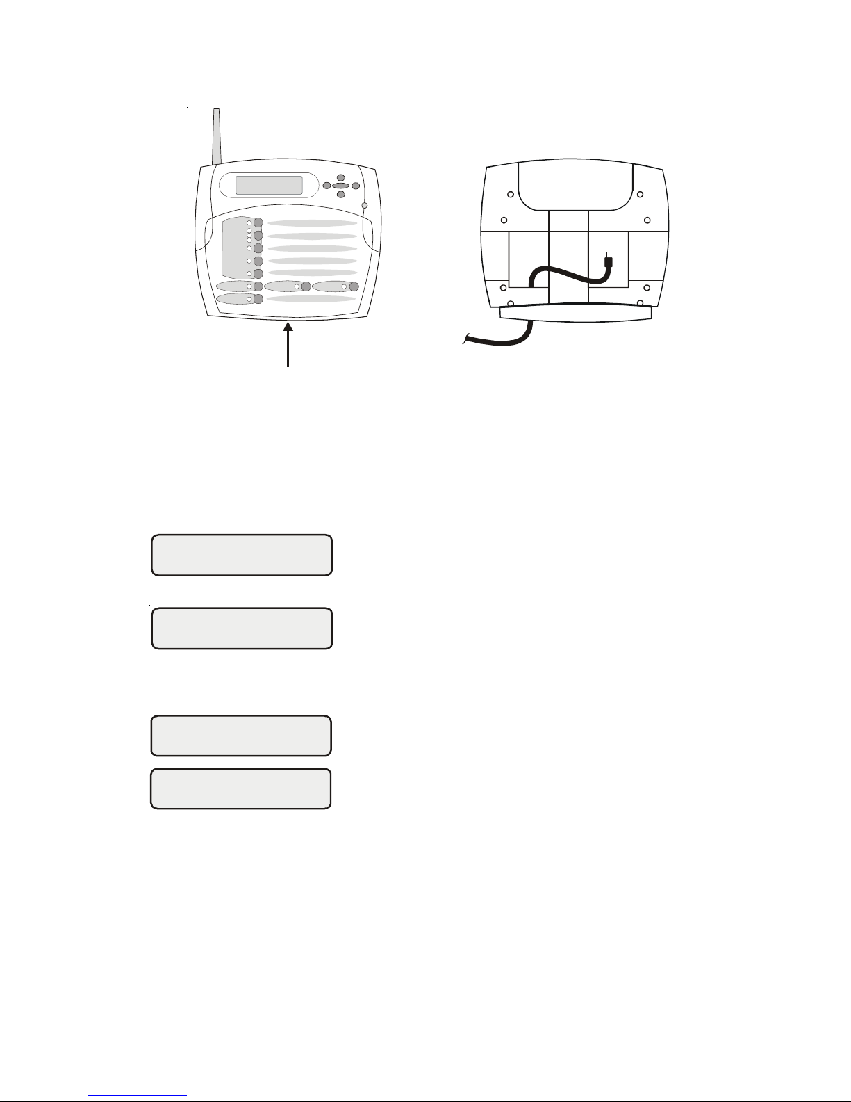
e. Reattach the wireless remote display/keypad to the baseplate.
f . Plug the power supply into a 120VAC outlet.
4. T each the unique Aqua Logic ID code: The base receiver attached to the Aqua
Logic control unit has a unique ID code that ensures that your unit will not affect
other systems in the neighborhood, and likewise, their remote will not affect
your system. To teach the ID code to the wireless remote unit:
a. On any other Aqua Logic display/keypad unit,
press the “Menu” button (possibly multiple
times) until “Settings Menu” is displayed.
b. Press “<“ or “>” (again, possibly multiple times)
until “Teach Wireless” is displayed.
c. Press the “+” button to start the teaching pro-
cess.
d. Press and hold any button on the wireless re-
mote display/keypad for 4 seconds. At this
point the LCD on the wireless remote display/
keypad will indicate "T each W ireless Successful" and the local display/keypad on the Aqua
Logic control unit will also confirm “Teach
Wireless Successful”. If this process is not
successful, then refer to the Troubleshooting
section of this manual for additional information.
5. Apply labels: The Aqua Logic PS series of controls allow each output (e.g.
AUX1) to be renamed to what is actually being controlled. The wireless remote
display/keypad comes with a sheet of name labels—simply peel the appropriate
label off the sheet and apply to the appropriate set of buttons on the wireless
remote display/keypad.
6. Installation is complete: Y ou can now use the wireless remote display/keypad.
2
Settings
Menu
Teach Wireless:
+ to start
Teach Wireless:
Successful
Press and hold
wireless button
Pull up on bottom edge
to remove cover
Wireless Remote
Display unit
 Loading...