

Page 1
Remote Display
for
Aqua LogicAqua Logic
Aqua Logic
Aqua LogicAqua Logic
Automation and Chlorination
®
G
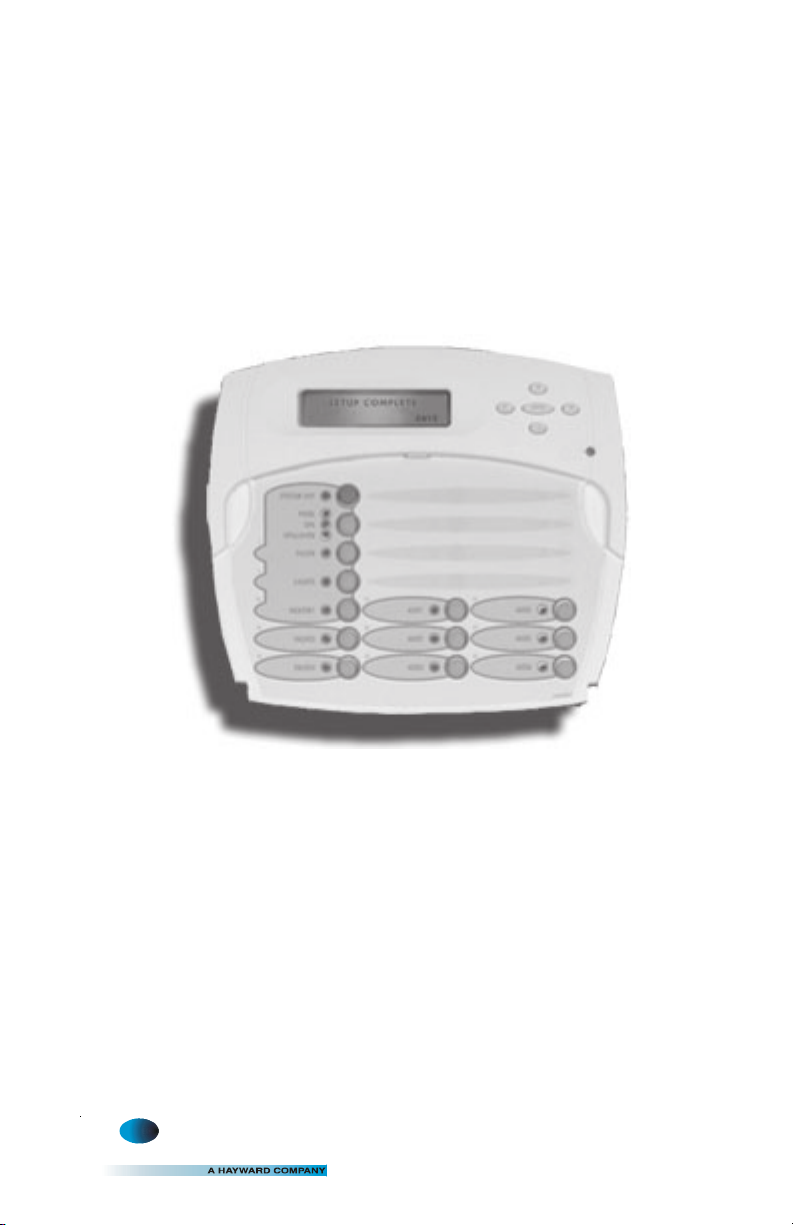
(model AQL-WW-PS-8 shown above)
Installation/Operation Manual
for model
AQL-WW-PS-4
AQL-WW-PS-8
AQL-WW-PS-16
LD
LINE
C
ONTROLS
www.goldlinecontrols.com
888-921-7665
Page 2
COMPATIBILITY: This display/keypad is compatible with all Aqua Logic-PS-4/8/16
systems running main software r2.00 or higher.
INSTALLATION
Mounting
The AQL-WW-PS-4/8/16 Aqua Logic Remote Display/Keypad must be mounted indoors or in a weather protected area (rain should never hit the display/keypad). Up to
3 remote display/keypads can be installed. The display/keypad is designed to mount
onto a standard electrical utility box (same size as used for a triple light switch) or can
be mounted directly onto any wall surface. When selecting a location, note that the
wire to the Aqua Logic main unit must be less than 500 feet long. Follow the steps
below:
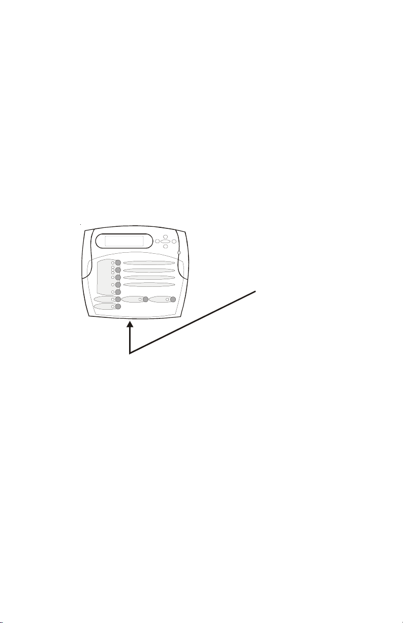
1. Remove display/keypad baseplate from the cover by lifting up on the cover at the
lower end of the keypad as shown below.
Pull up on bottom edge
to remove cover
2. Screw the baseplate in the desired position (screws supplied by installer).
Wiring
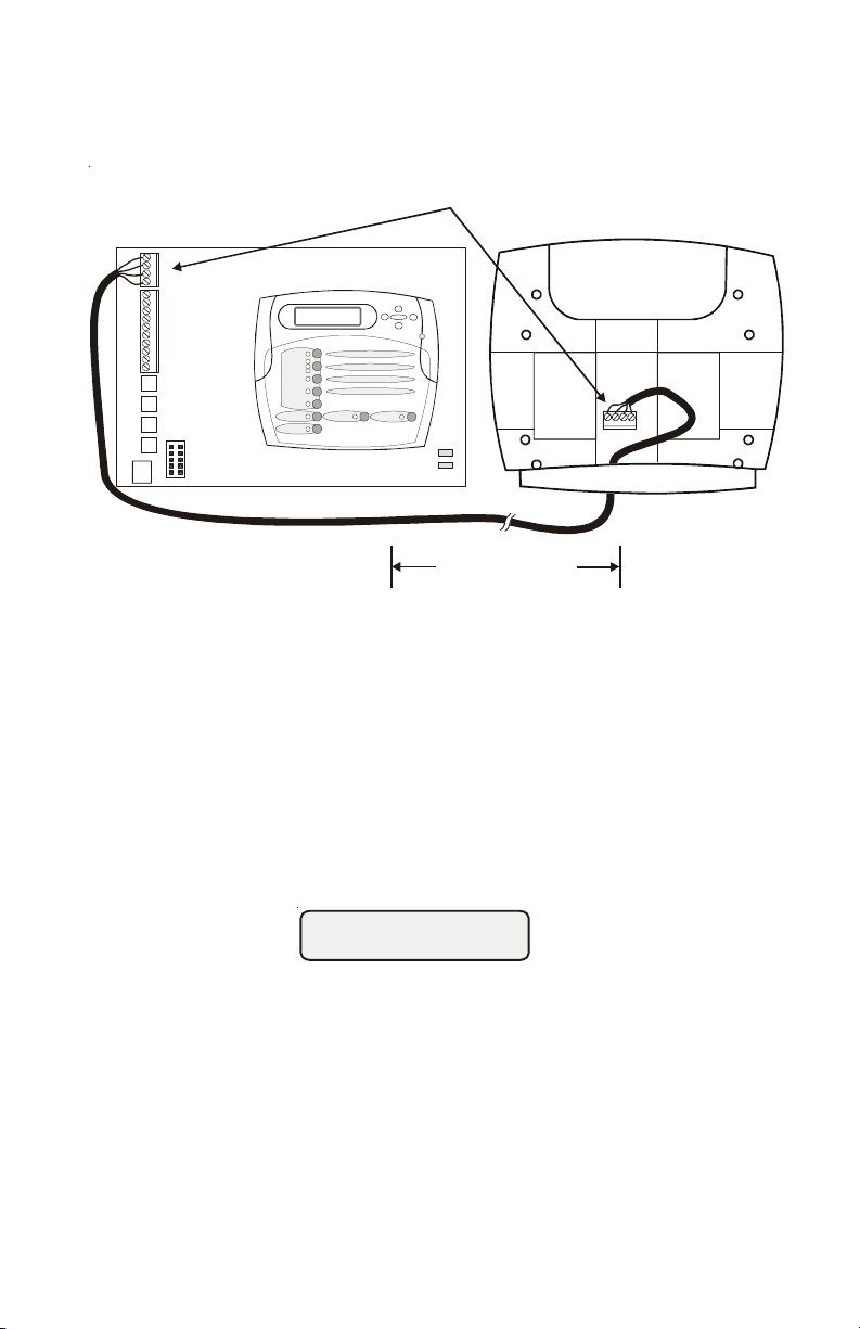
The Aqua Logic main unit can connect to a maximum of 3 remote display/keypads.
Use four conductor cable (typically phone cable) to connect the remote display/
keypad with the Aqua Logic Control Center as shown on page 2. The maximum wiring
distance is 500ft. (160m). Note that the terminals on both the Aqua Logic main unit
and the remote display/keypad are numbered: Connect 1 to 1, 2 to 2, etc. Refer to
diagram on the top of the following page.
If multiple remote display/keypads are installed: Never connect more than 2 wires to
any terminal block. Two remotes can be wired back to the Aqua Logic main unit or the
second display/keypad (and third, if applicable) can be “daisy chained” with one
display/keypad wired to the next. The maximum wire run from the Aqua Logic main
unit to the furthest remote display/keypad is 500 ft. (160m).
1 6
Page 3
A
Connect screw terminals
“1” to “1”, “2” to “2”, etc.
1
2
3
4
qua Logic Control Center
Wired Remote
Display unit
12
34
500 ft max
OPERATION
When power is turned on, all the LED indicators will flash briefly, the display backlight will illuminate, and the following display will appear for a short period of time:
Goldline Aqua Logic
Display r3.00
The "r3.00" is the software revision level. The actual revision level for your display/
keypad may be different.
Refer to the Aqua Logic Operation Manual for complete operating instructions.
25
Page 4

TROUBLESHOOTING
1. Display/keypad not functioning (no display, no LEDs illuminated)
2. Display backlight turns off after a period of time
3. Display backlight always on
If the display/keypad located on the main unit is working correctly, the most
likely cause is that wires 1 and 4 are either open circuited or reversed. Check
wiring. If none of the displays are working, check that 120V power is being
applied to the main control and that the 3A fuse (violet) is not blown.
The display backlight should always illuminate when you press any key on
the unit. If it turns off after a period of time, you can stop this by pressing the
menu key (possibly multiple times) until “Settings Menu” appears. Next
press the “<” or “>” key (possibly multiple times) until “Display Light”
appears. At this point, pressing either “+” or “-“ will allow you to select
either “Always On” or “On for 60 sec.”. After you have selected the desired
operation, press the “Menu” button to lock in your setting. Note that this
selection applies to this display/keypad only. Repeat the process of each
display/keypad in the system.
The display backlight should always illuminate when you press any key on
the unit. If it remains on after 60 seconds have elapsed since the last button
push, you can stop this by pressing the menu key (possibly multiple times)
until “Settings Menu” appears. Next press the “<” or “>” key (possibly
multiple times) until “Display Light” appears. At this point, pressing either
“+” or “-“ will allow you select either “Always On” or “On for 60 sec.”. After
you have selected the desired operation, press the “Menu” button to lock in
your setting. Note that this selection applies to this display/keypad only.
Repeat the process for each display/keypad in the system.
4.
5.
Communication Err 1
call 888-921-7665
The display/keypad received data from an Aqua Logic-P-4 system or an
Aqua Logic -PS-4 system running software earlier than r2.00. This keypad is
not compatible with these Aqua Logic systems. Another cause for this
problem may be that the local display/keypad in the main Aqua Logic control
unit is not connected or not functioning. If this is the case, connect and/or
replace the local display/keypad and then cycle power to the Aqua Logic off
and then back on to reset the system. Call the Goldline Tech support department (Monday through Friday, from 8AM to 8PM eastern time) for further
assistance.
Communication 2
call 888-921-7665
The display/keypad is not receiving any communication from the Aqua Logic
main control unit. The most likely cause of this problem is a broken wire or
"open circuit" in wires "2" and/or "3" in the cable between the display/
keypad and the Aqua Logic main control unit. If you are unable to find the
problem, contact the Goldline Tech support department Monday through
Friday, from 8AM to 8PM eastern time.
Err
Page 5

6.
Communication 3
call 888-921-7665
Err
The display/keypad is receiving data from the main Aqua Logic control unit
however that data contains errors and is unusable. The most likely cause of
this problem is that wires "2" and "3" in the cable between the control unit
and the display/keypad are crossed. If you are unable to find the problem,
contact the Goldline Tech support department Monday through Friday, from
8AM to 8PM eastern time.
7.
Display Error 1
call 888-921-7665
Display Error 2
call 888-921-7665
An internal problem has occurred in the display/keypad. Remove the display/keypad from the wall mount base (see diagram on page 1) and write
down the model number and serial number of the display/keypad. Next, call
the Goldline Tech support department (Monday through Friday, from 8AM
to 8PM eastern time) to find out how to obtain a replacement display/keypad.
43
Page 6

A
Page 7

LIMITED WARRANTY Goldline warrants its Aqua Rite, Aqua Rite Pro, Aqua Trol, Aqua Logic
and Pro Logic products (products with Goldline part numbers starting with AQ-RITE-, AQ-RTPRO, AQ-TROL-, AQ-LOGIC-, AQL-P-, AQL-PS-, AQL-CL-, PL-P-, PL-PS-, and HPC-2) to
be free from defects in material or workmanship, under normal use and service:
For three years from the date of the initial system installation on private, residential swim-
ming pools within the USA or Canada and one year from the date of initial system installation
on commercial installations, installations outside of the USA or Canada and for any replacement parts or accessory products, provided they are installed in accordance with the Goldline
installation instructions and specifications provided with the product. If written proof of the
date of the initial system installation is not provided to Goldline, the manufacturing datecode
on the Aqua Rite, Aqua Rite Pro, Aqua Trol, Aqua Logic and Pro Logic electronics unit will be
the sole determinant of the date of the initial system installation.
For residential installations in USA or Canada: If a product is defective in workmanship or
materials and is removed and returned freight prepaid within three (3) years after the date of the
initial system installation, Goldline will, at its option, either repair or replace the defective
product and return it freight prepaid.
For commercial installations, installations outside the USA and Canada, and accessory products
and replacement parts: If a product is defective in workmanship or materials and is removed and
returned freight prepaid within one (1) year after the date of the initial system installation,
Goldline will, at its option, either repair or replace the defective product and return it freight
prepaid.
Contact any Goldline dealer or contact Goldline at 61 Whitecap Drive, North Kingstown, RI
02852 for warranty service. The costs incurred in removal and/or reinstallation of the product
are NOT covered under this warranty. Some states do not allow limitations on how long an
implied warranty lasts, so the above limitation may not apply to you.
WARRANTY EXCLUSIONS:
1. Material supplied or workmanship performed by others in process of installation.
2. Damage resulting from improper installation including installation on pools larger than
the product rating.
3. Problems resulting from failure to operate the product(s) in accordance with the recommended instructions contained in product’s owners manual(s).
4. Problems resulting from failure to maintain pool water chemistry in accordance with the
recommendations in the owners manual(s).
5. Problems resulting from tampering, accident, abuse, negligence, unauthorized repairs or
alternations, fire, flood, lightning, freezing, external water, degradation of natural stone
used in or immediately adjacent to a pool or spa, war or acts of God.
DISCLAIMER. THE EXPRESS LIMITED WARRANTY ABOVE CONSTITUTES THE
ENTIRE WARRANTY OF GOLDLINE WITH RESPECT TO ITS POOL AUTOMATION
AND CHLORINATION PRODUCTS AND IS IN LIEU OF ALL OTHER WARRANTIES,
EXPRESSED OR IMPLIED, INCLUDING WARRANTIES OF MERCHANTABILITY OR
FITNESS FOR A PARTICULAR PURPOSE. THIS WARRANTY GIVES YOU SPECIFIC
LEGAL RIGHTS, AND YOU MAY ALSO HAVE OTHER RIGHTS WHICH VARY FROM
STATE TO STATE. IN NO EVENT SHALL GOLDLINE BE RESPONSIBLE FOR ANY
CONSEQUENTIAL, SPECIAL OR INCIDENTAL DAMAGES OF ANY NATURE WHATSOEVER, INCLUDING, BUT NOT LIMITED TO, PERSONAL INJURY, PROPERTY DAMAGE, DAMAGE TO OR LOSS OF EQUIPMENT, LOST PROFITS OR REVENUE, COSTS
OF RENTING REPLACEMENTS, AND OTHER ADDITIONAL EXPENSES, EVEN IF THE
SELLER HAD BEEN ADVISED OF THE POSSIBILITY OF SUCH DAMAGES. SOME
STATES DO NOT ALLOW THE EXCLUSION OF LIMITATION OF INCIDENTAL OR
CONSEQUENTIAL DAMAGES, SO THE ABOVE LIMITATION OR EXCLUSION MAY
NOT APPLY TO YOU.
NO WHOLESALER, AGENT, DEALER, CONTRACTOR OR OTHER PERSON IS AUTHORIZED TO GIVE ANY WARRANTY ON BEHALF OF GOLDLINE.
THIS WARRANTY IS VOID IF THE PRODUCT HAS BEEN ALTERED IN ANY WAY
AFTER LEAVING THE FACTORY.
Page 8

ELECTROLYTIC CHLORINE GENERATOR
A
T
BASIC POOL MAINTENANCE REQUIREMENTS
TEST IDEAL RANGE ADJUSTMENT REQUIRED
Free Chlorine 1.0 - 3.0 ppm Turn output dial up to increase,
WEEKLY
pH 7.2 - 7.6
down to decrease -OR- increase
or decrease pump filtration time.
Too high - add muriatic acid
Too low - add soda ash.
Alkalinity 80 - 120 ppm
Salt 2700 - 3400 ppm Add salt as required to increase.
MONTHLY
Stabilizer 60 - 80 ppm Add cyanuric acid to increase.
Calcium 200 - 400 ppm Add calcium to increase.
QUARTERLY
Electrolytic Cell inspect & clean Refer to section in manual.
Add baking soda to increase.
dd acid as required to decrease.
Drain and add water to decrease.
Questions?
Refer to www.goldlinecontrols.com for latest manual
revisions, additional information and helpful service. Or, you
may visit your local Authorized Goldline Dealer or call 888-921-
POOL (7665) for assistance.
G
North Kingstown, RI 02852 USA
LD
LINE
C
ONTROLS
Copyright © 2004 Goldine Controls, Inc
092041E
 Loading...