

Page 1
Remote Control
for
and
Aqua LogicAqua Logic
Aqua Logic
Aqua LogicAqua Logic
Automation and Chlorination
®
G
Installation and Operation Manual
for model
AQL-WW-P-4
LD
LINE
C
ONTROLS
www.goldlinecontrols.com
888-921-7665
Page 2

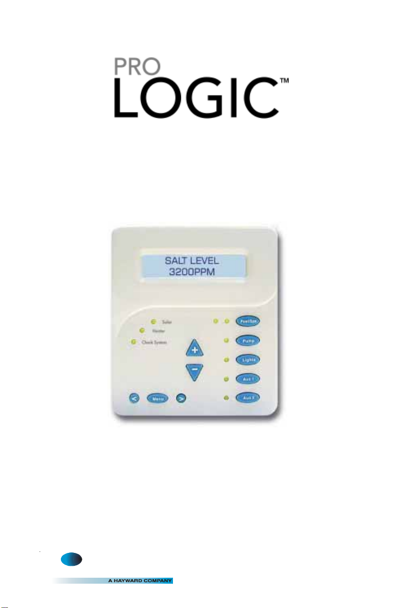
OPERA TION
Refer to the Pro Logic or Aqua Logic Operation Manual for complete AQL-WW-P4
operating instructions.
Start-up
When power is turned on, the display backlight should immediately illuminate and the
following display should appear for a few seconds:
PRO LOGIC
rx.xx
The x.xx is the software revision level for this particular display/keypad.
TROUBLESHOOTING
1. Display/keypad not functioning (no display, no LEDs illuminated)
2. “Communication Error” displayed
3. Display backlight turns off after a period of time
4. Display backlight always on
If the display/keypad located on the main unit is working correctly , the most
likely cause is that wires 1 and 4 are either open circuited or reversed. Check
wiring. If none of the displays are working, check that 120V power is being
applied to the main control and that the 3A fuse (violet) is not blown.
If the display/keypad on the main unit is working correctly, the most likely
cause is that wires 2 and 3 are either open circuited or reversed. If all the
display/keypads are showing “Communication Error”, unplug the remote
display connector at the main unit and check the main display. If the main
display works properly, the problem is in the wiring or one of the remotes is
defective. If the main display keypad still does not work, the main PCB will
have to be replaced.
The display backlight should always illuminate when you press any key on
the unit. If it turns off after a period of time, you can stop this by pressing the
menu key (possibly multiple times) until “Settings Menu” appears. Next
press the “<” or “>” key (possibly multiple times) until “Display Light”
appears. At this point, pressing either “+” or “-“ will allow you to select
either “Always On” or “Off after 60 sec.”. After you have selected the
desired operation, press the “Menu” button to lock in your setting. Note
that this selection applies to this display/keypad only. Repeat the process of
each display/keypad in the system.
The display backlight should always illuminate when you press any key on
the unit. If it remains on after 60 seconds have elapsed since the last button
push, you can stop this by pressing the menu key (possibly multiple times)
until “Settings Menu” appears. Next press the “<” or “>” key (possibly
multiple times) until “Display Light” appears. At this point, pressing either
“+” or “-“ will allow you select either “Always On” or “Off after 60 sec.”.
After you have selected the desired operation, press the “Menu” button to
lock in your setting. Note that this selection applies to this display/keypad
only. Repeat the process of each display/keypad in the system.
Page 3

COMP ATIBILITY: This display/keypad is compatible with all Pro Logic and Aqua
A
Logic P-4 systems. In addition, it is compatible with Aqua Logic PS-4 system with
datecodes 0311 and earlier running main software r1.04 or lower .
INST ALLATION
Mounting
The AQL-WW -P4 Remote Control must be mounted indoors or in a weather protected
area (rain should never hit the display/keypad). Up to 3 remote display/keypads can
be installed. The display/keypad is designed to mount onto a standard electrical
utility box (ideal for new construction) or can be mounted directly onto any wall
surface. When selecting a location, note that the wire to the main unit must be less
than 500’ long. Follow the steps below:
1 . Remove display/keypad baseplate from the cover by lifting up on the cover at the
lower end of the keypad as shown below.
Remote Keypad
push up here
to remove co ver
2. Screw the baseplate in the desired position (screws supplied by installer).
Wiring
The Pro Logic or Aqua Logic main unit can connect to a maximum of 3 remote display/
keypads.
Use four conductor cable (typically phone cable) to connect the remote control to the
Pro Logic/Aqua Logic Control Center as shown below. The maximum wiring distance
is 500ft. (160m). Note that the terminals on both the main unit and the remote display/
keypad are numbered: Connect 1 to 1, 2 to 2, etc. Refer to diagram on the top of the
following page.
If multiple remote remote controls are installed: Never connect more than 2 wires to
any terminal block. T wo remotes can be wired back to the Pro Logic/Aqua Logic main
unit or the second display/keypad (and third, if applicable) can be “daisy chained”
with one display/keypad wired to the next. The maximum wire run from the main unit
to the furthest remote display/keypad is 500 ft (160m).
3.75
1
2
3
4
x
x
Remote Display unit
”
1234
Concealed Wiring
500 ft max
4.50
”
lternative
Page 4

ELECTROLYTIC CHLORINE GENERATOR
T
BASIC POOL MAINTENANCE REQUIREMENTS
TEST IDEAL RANGE ADJUSTMENT REQUIRED
Free Chlorine 1.0 - 3.0 ppm Turn output dial up to increase,
WEEKLY
pH 7.2 - 7.8
Alkalinity 80 - 120 ppm
MONTHLY
Salt 2700 - 3400 ppm Add salt as required to increase.
Stabilizer 60 - 80 ppm Add cyanuric acid to increase.
Calcium 200 - 400 ppm Add calcium to increase.
QUARTERLY
Electrolytic Cell inspect & clean Refer to section in manual.
down to decrease -OR- increase
or decrease pump filtration time.
Too high - add muriatic acid
Too low - add soda ash.
Add baking soda to increase.
Add acid as required to decrease.
Drain and add water to decrease.
Questions?
Refer to www.goldlinecontrols.com for latest manual
revisions, additional information and helpful service. Or, you
may visit your local Authorized Goldline Dealer or call 888-921-
POOL (7665) for assistance.
G
LD
North Kingstown, RI 02852 USA
LINE
C
ONTROLS
Copyright © 2008 Goldine Controls
092037E
 Loading...