

Page 1
Aqua LogicAqua Logic
Aqua Logic
Aqua LogicAqua Logic
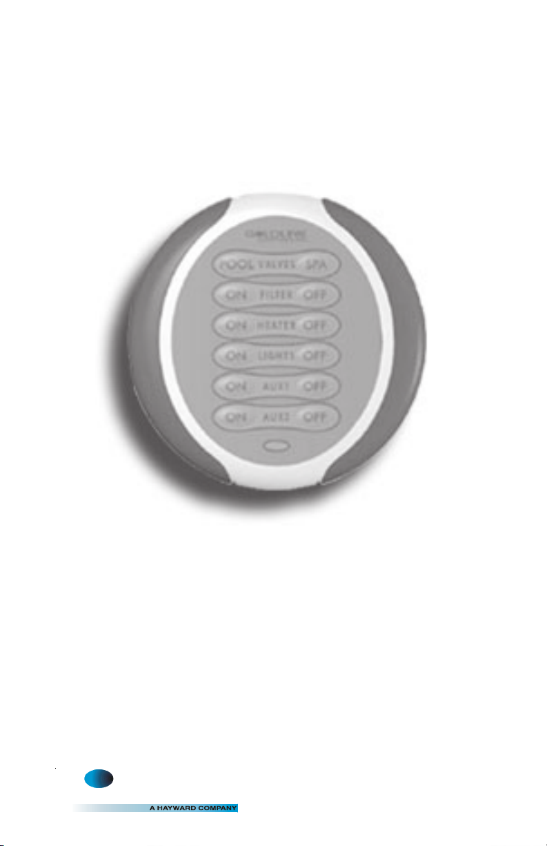
Spa-side Remote
®
G
Installation/Operation Manual
for model
AQL-SS-RF
LD
LINE
ONTROLS
C
www.goldlinecontrols.com
888-921-7665
Page 2

Compatibility
This product is compatible with all Aqua Logic controls operating with software revision r1.10 or higher. To verify the software level of your Aqua Logic control, press the
Menu button (possibly multiple times) until “Diagnostic Menu” is displayed. Next,
press the “>” or “<“ keys (possibly multiple times) until the main and display software
revision levels are displayed (the “main” rev should be r1.10 or higher).
If the software revision level is less than r1.10 contact the Goldline Technical Service
Dept. from Monday through Friday, 8AM to 8PM Eastern at 888-921-7665 for information on upgrades.
Installation
1. Batteries are installed at the factory: There is no need to open the spa-side
unit.
2. Base Receiver required: For operation of the spa-side remote, the Aqua Logic
control unit must have a base receiver (AQL-BASE-RF) installed. The receiver
allows the Aqua Logic control until to communicate with the spa-side remote.
3. Teach the unique Aqua Logic ID code: The base receiver attached to the Aqua
Logic control unit has a unique ID code that ensures that your unit will not affect
other systems in the neighborhood, and likewise, their remote will not affect
your system. To teach the ID code to the spa-side remote unit:
Settings
Menu
Teach Wireless:
+ to start
Press and hold
wireless button
Teach Wireless:
Successful
4. Apply labels: Aqua Logic PS series of control allow each output (e.g. AUX1) to
be re-named to what is actually being controlled. The spa-side remote comes
with a sheet of name labels—simply peel the appropriate label off the sheet and
apply to the appropriate set of buttons on the spa-side remote.
5. Installation is complete: you can now use the spa-side wireless remote.
a. On any Aqua Logic display/keypad unit
press the “Menu” button (possibly multiple
times) until “Settings Menu” is displayed.
b. Press “<“ or “>” (again, possibly multiple
times) until “Teach Wireless” is displayed.
c. Press the “+” button to start the teaching
process.
d. Press and hold any button on the spa-side
remote for 4 seconds. At this point the LED
indicator on the spa-side remote should flash
3 times and the Aqua Logic display should
say “Teach Wireless, Successful”. If the
LED indicator does not flash, then refer to
the Troubleshooting section of this manual
for additional information.
1 6
Page 3

Operation
The spa-side remote communicates with the base receiver on the Aqua Logic control
unit using RF (radio frequency) technology. When you push a button on the spa-side
remote, it sends a command and flashes the LED indicator once. After the spa-side
remote receives a confirmation from the Aqua Logic base the receiver, the LED indicator on the spa-side remote flashes a 2nd time. Thus, 2 LED flashes are your confirmation that your command has been successfully transmitted to the Aqua Logic control unit. If the LED doesn’t flash at all or else just flashes once after you’ve pushed
a button, refer to the Troubleshooting section for assistance in resolving these problems.
G
LDLINE
CONTROLS INC.
POOL SPA
VALVE S
FILTER
ON OFF
HEATER
ON OFF
LIGHTS
ON OFF
ON OFF
ON OFF
AUX1
AUX2
Valves POOL/SPA These buttons will allow you to select either pool or spa opera-
tion. You can not select spa spillover operation from the spaside remote.
Filter ON/OFF The ON/OFF buttons allow manual operation that will override
any automatic control settings (e.g. timeclock). The manual
setting will remain active until the next scheduled automatic
turn on/off event. There are some exceptions:
If the Heater1 is operating and the heater cooldown function is
enabled, then pressing the OFF button will turn off the heater
and the pump will run for another 15 minutes to allow the
heater to cooldown before automatically turning off
If the freeze protection feature is enabled and the air temperature is below the selected freeze protection threshold (38°F
default), then the pump will remain on to ensure that the pipes
do not freeze.
25
Page 4

Heater ON/OFF Provided that the filter pump is running, normal Aqua Logic op-
eration will turn the heater (Aqua Logic HEATER1 output) on
until the desired temperature (see Settings Menu) is attained.
The heater will then turn on periodically, as required, to maintain
that temperature. When the "ON" button is pushed, the heater
will turn on for a minimum of 5 minutes or until the water reaches
104°F This allows people in the spa to temporarily override the
normal temperature setting. When the "OFF" button is pushed,
the heater is turned off regardless of the water temperature and
will remain off until either the "ON" button is pressed, or the start
of the next normal filter timer period.
Lights ON/OFF The "ON"/"OFF" buttons allow manual operation that will over-
ride any automatic control settings (e.g. timeclock). The manual
setting will remain active until the next scheduled automatic turn
on/off event.
Aux1 ON/OFF The "ON"/"OFF" buttons allow manual operation that will over-
ride any automatic control settings (e.g. timeclock). The manual
setting will remain active until the next scheduled automatic turn
on/off event. Note that the Aux3 - Aux6 outputs on Aqua Logic PS-8 models (Aux3-Aux14 on PS-16 models) can NOT be controlled by this remote.
Battery Replacement
The spa-side remote runs on two AAA batteries. Since the internal circuits are only
active when you push a button, it is anticipated that the original, factory-installed,
batteries should provide years of service. If you do not at least see a single flash of the
LED indicator when you push a button, then the batteries may need replacement.
It is IMPORTANT that you carefully follow this procedure to ensure that your spaside remote retains its watertight integrity:
1. Use a Phillips head screwdriver to remove the 4 screws on the back of the spa-
side remote. These are special screws with built-in O-rings and are an important
part of making the spa-side remote watertight.
2. Separate the 2 halves of the remote. Do not touch the O-rings or allow any
debris to fall onto the O-ring surface.
3. Replace the 2 AAA batteries. Alkaline batteries are recommended for maxi-
mum life. If you observe any corrosion or water damage, contact the Goldline
Technical Service Dept. Monday through Friday, 8AM to 8PM at 888-921-7665
for assistance.
4. Carefully replace the back cover on the spa-side remote
5. Reinstall all 4 of the original screws.
6. The spa-side remote will remember the ID code of the Aqua Logic base receiver,
a. Loosely tighten all four screws
b. Then go back and firmly tighten each screw.
so it is not necessary to perform the “Teach Wireless” procedure again. Verify
proper operation by pressing any button and observing 2 quick flashes indicating that the message was transmitted to the Aqua Logic base receiver and a
confirmation was received.
Page 5

Troubleshooting
If you have questions, you may call the Goldline Technical Service Dept. from Monday through Friday, 8AM to 8PM Eastern at 888-921-7665.
1. Can’t find the “Teach Wireless” display: Press the “menu” button (possibly
more than once) until “Settings Menu” is displayed. Next, press the “<“ or “>”
buttons (possibly more than once) unit the “Teach Wireless” display appears.
If you get to the point where “Settings Menu” appears again, then this means
that the Aqua Logic control unit is not communicating with the base receiver.
Check that the 4 wire cable from the base receiver is plugged into the “wireless" connector on the main printed circuit board. If this connector is already
plugged in (for more than 30 seconds), then call Goldline Technical Service for
assistance.
2. “Teach Wireless” failed: Ensure that the remote is powered when pressing
the button. This is indicated by a single flash of the LED on the spa-side
remote or a message on the display of the in-house remotes. If the remote is
powered, then the next most likely cause is that the distance between the base
receiver and the remote is too great—try moving the remote closer to the receiver. Lastly, there may be other equipment in the neighborhood that is using
the same frequency. To see if this is the case, go to the Settings Menu/Wireless
Channel and select another channel. Note that after you change the channel
you will have to “re-teach” every wireless remote device in the system.
3. Unreliable communication with remote devices: The most likely cause is
that the distance between the base receiver and the remote is too great—try
moving the remote closer to the receiver. Lastly, there may be other equipment
in the neighborhood that is using the same frequency. To see if this is the case,
go to the Settings Menu/Wireless Channel and select another channel. Note
that after you change the channel you will have to “re-teach” every wireless
remote device in the system.
4. Single LED flash when a button is pushed: The radio signal may be too
weak—try pointing the spa-side remote in the direction of the pool equipment
or try moving closer to the pool equipment. If that doesn’t work, then try the
“Teach Wireless” procedure to ensure that the remote knows the ID code of the
base receiver and also what channel to communicate on. If this procedure is
not successful, then refer to the “Teach Wireless” failed section above.
5. The filter pump won’t turn off when the "OFF" button is pressed: (1) If the
heater cooldown feature is enabled and the heater is on, then pressing the
"OFF" button will cause the heater to turn off but leave the filter pump running
for 15 more minutes to allow the heater to cooldown. Pressing the "OFF"
button a 2nd time will override the cooldown period and turn the pump off. (2)
If the freeze protection feature is enabled and the air temperature is less than
38°F then the pump will run continuously and any OFF button press will be
disregarded.
6. Functions won’t turn on when the "ON" button is pressed: (1) If the "SYSTEM OFF" button (Aqua Logic PS versions only) has been pushed then all
functions are disabled. Press the "System Off" button again to resume normal
operation. (2) If the Aqua Logic system is in service mode, then functions can
only be turned on at the main unit display/keypad. Press the "SERVICE"
button once (or twice) until normal operation is restored. (3) The filter pump is
turned off for a short period of time while the valves are rotating. Normal
operation will resume automatically when the valve(s) have finished their rotation.
43
Page 6

LIMITED WARRANTY Goldline warrants its Aqua Rite, Aqua Rite Pro, Aqua Trol, Aqua Logic
and Pro Logic products (products with Goldline part numbers starting with AQ-RITE-, AQ-RTPRO, AQ-TROL-, AQ-LOGIC-, AQL-P-, AQL-PS-, AQL-CL-, PL-P-, PL-PS-, and HPC-2) to
be free from defects in material or workmanship, under normal use and service:
For three years from the date of the initial system installation on private, residential swim-
ming pools within the USA or Canada and one year from the date of initial system installation
on commercial installations, installations outside of the USA or Canada and for any replacement parts or accessory products, provided they are installed in accordance with the Goldline
installation instructions and specifications provided with the product. If written proof of the
date of the initial system installation is not provided to Goldline, the manufacturing datecode
on the Aqua Rite, Aqua Rite Pro, Aqua Trol, Aqua Logic and Pro Logic electronics unit will be
the sole determinant of the date of the initial system installation.
For residential installations in USA or Canada: If a product is defective in workmanship or
materials and is removed and returned freight prepaid within three (3) years after the date of the
initial system installation, Goldline will, at its option, either repair or replace the defective
product and return it freight prepaid.
For commercial installations, installations outside the USA and Canada, and accessory products
and replacement parts: If a product is defective in workmanship or materials and is removed and
returned freight prepaid within one (1) year after the date of the initial system installation,
Goldline will, at its option, either repair or replace the defective product and return it freight
prepaid.
Contact any Goldline dealer or contact Goldline at 61 Whitecap Drive, North Kingstown, RI
02852 for warranty service. The costs incurred in removal and/or reinstallation of the product
are NOT covered under this warranty. Some states do not allow limitations on how long an
implied warranty lasts, so the above limitation may not apply to you.
WARRANTY EXCLUSIONS:
1. Material supplied or workmanship performed by others in process of installation.
2. Damage resulting from improper installation including installation on pools larger than
the product rating.
3. Problems resulting from failure to operate the product(s) in accordance with the recommended instructions contained in product’s owners manual(s).
4. Problems resulting from failure to maintain pool water chemistry in accordance with the
recommendations in the owners manual(s).
5. Problems resulting from tampering, accident, abuse, negligence, unauthorized repairs or
alternations, fire, flood, lightning, freezing, external water, degradation of natural stone
used in or immediately adjacent to a pool or spa, war or acts of God.
DISCLAIMER. THE EXPRESS LIMITED WARRANTY ABOVE CONSTITUTES THE
ENTIRE WARRANTY OF GOLDLINE WITH RESPECT TO ITS POOL AUTOMATION
AND CHLORINATION PRODUCTS AND IS IN LIEU OF ALL OTHER WARRANTIES,
EXPRESSED OR IMPLIED, INCLUDING WARRANTIES OF MERCHANTABILITY OR
FITNESS FOR A PARTICULAR PURPOSE. THIS WARRANTY GIVES YOU SPECIFIC
LEGAL RIGHTS, AND YOU MAY ALSO HAVE OTHER RIGHTS WHICH VARY FROM
STATE TO STATE. IN NO EVENT SHALL GOLDLINE BE RESPONSIBLE FOR ANY
CONSEQUENTIAL, SPECIAL OR INCIDENTAL DAMAGES OF ANY NATURE WHATSOEVER, INCLUDING, BUT NOT LIMITED TO, PERSONAL INJURY, PROPERTY DAMAGE, DAMAGE TO OR LOSS OF EQUIPMENT, LOST PROFITS OR REVENUE, COSTS
OF RENTING REPLACEMENTS, AND OTHER ADDITIONAL EXPENSES, EVEN IF THE
SELLER HAD BEEN ADVISED OF THE POSSIBILITY OF SUCH DAMAGES. SOME
STATES DO NOT ALLOW THE EXCLUSION OF LIMITATION OF INCIDENTAL OR
CONSEQUENTIAL DAMAGES, SO THE ABOVE LIMITATION OR EXCLUSION MAY
NOT APPLY TO YOU.
NO WHOLESALER, AGENT, DEALER, CONTRACTOR OR OTHER PERSON IS AUTHORIZED TO GIVE ANY WARRANTY ON BEHALF OF GOLDLINE.
THIS WARRANTY IS VOID IF THE PRODUCT HAS BEEN ALTERED IN ANY WAY
AFTER LEAVING THE FACTORY.
Page 7

Page 8

FCC Statement
T
(Compliance Statement, Part 15.19): This device complies with Part 15 of the FCC
Rules. Operation is subject to the following two conditions: (1) This device may
not cause harmful interference, and (2) this device must accept any interference
received, including interference that may cause undesired operation.
WARNING (Part 15.21): Changes or modifications not expressly approved by the
party responsible for compliance could void the user’s authority to operate this
equipment.
Industry Canada Statement
The term “IC” before the certification/registration number only signifies that the
Industry Canada technical specifications were met.
Interference
This equipment has been tested and found to comply with the limits for a Class B
digital device, pursuant to Part 15 of the FCC rules. These limits are designed to
provide reasonable protection against harmful interference in a residential installation. This equipment generates, uses, and can radiate radio frequency energy
and, if not installed and used in accordance with the instructions, may cause harmful interference to radio communications. However, there is no guarantee that
interference will not occur in a particular installation. If this equipment does cause
harmful interference to radio or television reception, which can be determined by
turning the equipment off and on, then the user is encouraged to try to correct the
interference by one or more of the following measures:
• Reorient or relocate the receiving antenna
• Increase the separation between the equipment and the receiver
• Connect the equipment into a power source on different circuit than the receiver.
G
North Kingstown, RI 02852 USA
LD
LINE
ONTROLS
C
Copyright © 2008 Goldine Controls
092039D
 Loading...